【0001】
【技術分野】
本発明は、光ファイバ整列用基板及び光ファイバアレイに係り、特に、複数の光ファイバを整列して固定する光ファイバ整列用基板と、それを用いて構成される光ファイバアレイのそれぞれの改良された構造に関するものである。
【0002】
【背景技術】
近年、情報伝送路の中で最も低損失で且つ大容量の伝送路の一つとして考えられる光ファイバを、通信用ケーブルとして利用した光ファイバ通信システムが、情報通信分野で大きな注目を浴びて、活発な開発が進められてきている。そして、このような光ファイバ通信システムにおいては、光ファイバを光導波路が内部に設けられた光合分波器等に接続する接続部品の一種として、光ファイバアレイが、一般的に用いられているのである。
【0003】
ところで、例えば、図7乃至図9に示されるように、従来の光ファイバアレイ50は、長さ方向の中間部に、長さ方向の一方側の部分を、その他方側部分よりも厚肉と為す段差面51が設けられた段付の平板からなる光ファイバ整列用基板52を有して、成っている。また、この光ファイバ整列用基板52にあっては、その薄肉部分が、平坦な上面を有する支持部53とされている一方、厚肉部分が、上面に、複数のV字状の凹溝54が互いに隣り合う並列状態において形成された整列部56とされている。そして、複数の光ファイバ58が、被覆部60が形成された部位において、光ファイバ整列用基板52の支持部53に支持されると共に、被覆部60が除去された先端部位からなる裸ファイバ部61において、整列部56の複数の凹溝54内にそれぞれ1本ずつ収容せしめられた状態で配置され、更に、それら各光ファイバ58の裸ファイバ部61が、整列部56の複数の凹溝54を覆蓋するように配置された押え部材62にて押さえ付けられている。そして、そのような状態下で、複数の光ファイバ58が、押え部材62と光ファイバ整列用基板52との間に形成された接着剤層64の内部に埋設されるようにして、それら押え部材62と光ファイバ整列用基板52とに固着されて、構成されているのである。
【0004】
かくして、従来の光ファイバアレイにあっては、複数の光ファイバ58が、光ファイバ整列用基板52の幅方向に、一定の間隔をもって整列せしめられつつ、固定せしめられており、以て、それら複数の光ファイバ58の一本一本が、光合分波器の光導波路等に確実に接続され得るように構成されているのである。
【0005】
ところが、かくの如き従来の光ファイバアレイを構成する光ファイバ整列用基板52においては、図9から明らかなように、支持部53と整列部56との間に、整列部56を支持部53よりも厚肉と為す、換言すれば、整列部56の上面を支持部53の上面よりも高い位置に位置せしめる段差面51が設けられているため、そのような段差面51と、整列部56に設けられた複数の凹溝54のそれぞれの側面68とにて、角張ったエッジ部70が不可避的に形成されていたのであり、それ故、そのようなエッジ部70の存在によって、数々の問題が惹起されていた。
【0006】
すなわち、光ファイバ整列用基板52の整列部56における各凹溝54内に、各光ファイバ58の裸ファイバ部61が収容せしめられる際に、例えば、位置ズレ等によって、それら各光ファイバ58の裸ファイバ部61が、段差面51と各凹溝54の側面68とにて形成された、角張ったエッジ部70に接触し、多少なりとも折れ曲がった状態で位置せしめられていると、光ファイバ58の裸ファイバ部61におけるエッジ部70との接触部位に、応力が集中せしめられ、それによって、伝送損失の増加や、光ファイバの損傷、更には断線等が惹起される恐れがあったのであり、また、各光ファイバ58の裸ファイバ部61に、前記位置ズレ等による折曲がりが生じていなくとも、各光ファイバ58の裸ファイバ部61がエッジ部70に接触せしめられていると、各光ファイバ58を光ファイバ整列用基板52に固着せしめる接着剤層64の硬化収縮や、温度サイクルによる膨張収縮等によって、光ファイバ58の被覆部60が除去された先端部位におけるエッジ部70との接触部位に、応力集中が惹起せしめられ、その結果として、上記と同様な問題が生ずる恐れもあったのである。
【0007】
かかる状況下、上述の如き問題の解消を図るために、支持部と整列部との間に形成される段差面を、凸状湾曲面と為して、エッジ部の長さを長くすることにより、光ファイバの裸ファイバ部のエッジ部との接触部分の長さを長くし、以てかかる光ファイバのエッジ部との接触部分における応力集中を緩和せしめるようにした光ファイバ整列用基板(例えば、特許文献1)や、整列部の各凹溝内に収容された光ファイバにおける、各凹溝における支持部側の端部に位置せしめられる部分が浮き上がるように、光ファイバを配置することによって、光ファイバの裸ファイバ部とエッジ部とが接触しないような構成した光ファイバコネクタ(例えば、特許文献2)等が、提案されている。
【0008】
しかしながら、それらの構造では、光ファイバ整列用基板に、角張ったエッジ部が未だ存在しているため、例えば、凹溝の加工精度や光ファイバの裸ファイバ部における寸法精度、或いは取付精度等が低いものであると、光ファイバの裸ファイバ部が、エッジ部に接触せしめられることがあり、そうなった場合には、結局、光ファイバのエッジ部との接触部位における応力集中が惹起されることとなるのであって、何等、根本的な解決策とはなっていなかったのである。
【0009】
【特許文献1】
特開2000−275478号公報
【特許文献2】
特開2002−131580号公報
【0010】
【解決課題】
ここにおいて、本発明は、上述せる如き事情を背景にして為されたものであって、その解決課題とするところは、光ファイバの被覆部が除去された先端部位(裸ファイバ部)に接触せしめられる角張ったエッジ部を完全に無くすことによって、かかる光ファイバの先端部位での応力集中の発生を解消し、以てそのような応力集中に起因する光ファイバの伝送損失の増大や損傷、断線等の発生を有利に防止し得るように改良された光ファイバ整列用基板と、そのような光ファイバ整列用基板を有して構成される光ファイバアレイとを提供することにある。
【0011】
【解決手段】
そして、本発明にあっては、かかる技術的課題のうち、光ファイバ整列用基板に係る課題の解決のために、(a)複数の光ファイバを支持する支持部と、(b)複数の凹溝が互いに隣り合う並列状態において形成されて、それら複数の凹溝内に、前記支持部にて支持された前記複数の光ファイバが、その被覆部が除去された先端部位において、それぞれ1本ずつ収容されることにより、該複数の光ファイバを整列せしめる整列部と、(c)それら支持部と整列部との間において、該整列部に形成された前記複数の凹溝のそれぞれにおける底部から該支持部に向かって、該凹溝の深さ以上の高さとなるまで立ち上がる傾斜面形態をもって延出するように設けられて、該凹溝を塞ぎ、前記支持部に支持された複数の光ファイバのそれぞれにおける前記被覆部が除去された先端部位を、各凹溝内にそれぞれ案内する傾斜案内面とを一体的に設けたことを特徴とする光ファイバ整列用基板を、その要旨とするものである。
【0012】
すなわち、この本発明に従う光ファイバ整列用基板にあっては、複数の光ファイバを支持する支持部と、複数の凹溝が形成された整列部との間に、傾斜案内面が、各凹溝の底部から支持部に向かって、立ち上がって延びるように、換言すれば、支持部から各凹溝の底部に向かって下傾して延出する状態で、一体的に形成されているところから、複数の凹溝のそれぞれの底部が、支持部よりも低い位置に位置せしめられているのであり、しかも、そのような傾斜案内面が、凹溝の深さ以上の高さとなるまで立ち上がって延出せしめられているため、最も高い部位で支持部と一体化される傾斜案内面の最大高さが、凹溝の深さ以上とされているのである。
【0013】
それ故、本発明に係る光ファイバ整列用基板においては、支持部の上面が、整列部の上面と同一の高さか若しくはそれよりも高い位置に位置せしめられるようになっており、それによって、支持部と整列部との間に、整列部の上面を支持部の上面よりも高い位置に位置せしめる段差面が設けられた従来品とは異なって、そのような段差面と各凹溝の側面とにて角張ったエッジ部が形成されるようなことが有利に回避され得て、かかるエッジ部を完全に無くすことが可能となっているのである。
【0014】
しかも、かかる光ファイバ整列用基板においては、支持部と整列部との間に、支持部から、整列部に設けられた複数の凹溝のそれぞれの底部に向かって、下傾して延びるように形成された傾斜案内面によって、支持部に支持された複数の光ファイバのそれぞれにおける被覆部が除去された先端部位が、各凹溝内にそれぞれ案内されるようになっているところから、かかる光ファイバの先端部位のうち、傾斜案内面にて案内される部分が、傾斜案内面に対して面接触せしめられるようになっているのである。
【0015】
従って、このような本発明に従う光ファイバ整列用基板にあっては、光ファイバが支持部に支持せしめられた状態下で、光ファイバの被覆部が除去された先端部位が角張ったエッジ部と接触せしめられることにより、かかる先端部位に応力集中が生ぜしめられることは勿論、光ファイバの先端部位の傾斜案内面との接触によって、光ファイバの先端部位に応力集中が惹起されるようなことも有利に解消され得るのであり、以て、そのような応力集中に起因する光ファイバの伝送損失の増大や損傷、断線等の発生が、効果的に防止され得ることとなるのである。
【0016】
なお、このような本発明に従う光ファイバ整列用基板の好ましい態様の一つによれば、前記支持部が、平坦な支持面を有して構成されて、前記複数の光ファイバが、かかる支持面によって水平に支持されるように構成される。
【0017】
このような構成を採用する場合には、例えば、整列部が支持部よりも厚肉とされた従来の光ファイバ整列用基板と、支持部の厚さを同じ厚さとすれば、かかる従来品に比して、全体の厚さを薄く為すことが出来、それによって、基板全体の小型化が有利に達成され得ることとなるのである。
【0018】
また、本発明に従う光ファイバ整列用基板の別の有利な態様の一つによれば、前記支持部が、前記傾斜案内面に向かって下傾する傾斜面からなる支持面を有して構成されて、前記複数の光ファイバが、前記被覆部が除去された先端部位を、該支持面に沿って下傾せしめた状態で、該支持面によって支持されるように構成される。
【0019】
このような構成を採用する場合には、支持面に沿って下傾して延びる、光ファイバの被覆部が除去された先端部位が、各凹溝内に収容せしめられた状態下において、各凹溝内の傾斜案内面側の端部で、各凹溝の底部や底部側の側面に接触することにより、かかる光ファイバの先端部位に対して、それを上方に湾曲せしめる作用力が作用せしめられて、光ファイバの先端部位が湾曲せしめられることとなる。そして、それによって、そのような各凹溝内の傾斜案内面側の端部内に位置せしめられる光ファイバの先端部位に、かかる作用力に対する反力が生ぜしめられて、湾曲せしめられた光ファイバの先端部位が、この反力にて、各凹溝の底部や底部側の側面に押し付けられることとなる。
【0020】
それ故、上述の如き構成を有する光ファイバ整列用基板にあっては、複数の光ファイバの全てが、各凹溝内で、その側面や底面に対して確実に接触せしめられた状態で、収容位置せしめられ得、その結果として、全ての光ファイバが、偏心せしめられることのない優れた位置精度をもって、整然と整列せしめられ得ることとなるのである。
【0021】
そして、本発明にあっては、前記光ファイバアレイに係る技術的課題を解決するために、前述せる如き特徴的な光ファイバ整列用基板に対して、複数の光ファイバを、前記支持部において支持させると共に、その被覆部が除去された先端部位において、前記整列部における複数の凹溝内にそれぞれ1本ずつ収容せしめた状態で配置する一方、該複数の凹溝を覆蓋しつつ、それら各凹溝内に収容された各光ファイバの先端部位を押さえ付ける押え部材にて、該複数の光ファイバの先端部位をそれぞれ押さえ付けた状態下で、該押え部材と該光ファイバ整列用基板とに対して、該複数の光ファイバを固着せしめて、構成したことを特徴とする光ファイバアレイをも、また、その要旨とするものである。
【0022】
要するに、この本発明に従う光ファイバアレイにおいては、複数の光ファイバを支持する支持部の上面が、複数の凹溝が設けられた整列部の上面と同一の高さか若しくはそれよりも高い位置に位置せしめられると共に、そのような支持部と整列部との間に、整列部における各凹溝の深さ以上の高さまで立ち上がって延びる傾斜案内面が一体的に形成されてなる光ファイバ整列用基板を有して、構成されているのであり、それによって、光ファイバ整列用基板が、かくの如き構造とされていることによって得られる効果が、有効に享受され得るのである。
【0023】
従って、このような本発明に従う光ファイバアレイにあっては、光ファイバの被覆部が除去された先端部位での応力集中の発生が有利に解消され得て、そのような応力集中に起因する光ファイバの伝送損失の増大や損傷、断線等の発生が、極めて効果的に防止され得ることとなるのであり、その結果として、良好な使用状態の維持と使用寿命の延命化とが、極めて有利に実現せしめられ得ることとなるのである。
【0024】
なお、このような本発明に従う光ファイバアレイの望ましい態様の一つによれば、前記押え部材が、前記光ファイバ整列用基板に設けられた前記傾斜案内面に対応する端部の前記複数の凹溝側に位置する角部において、面取りされた面取角部とされるか、或いは凸状湾曲面からなる湾曲角部とされることとなる。
【0025】
このような構成によれば、光ファイバの被覆部が除去された先端部位が、光ファイバ整列用基板の整列部に設けられた複数の凹溝側に位置する、押え部材の角部と接触せしめられることによって、かかる光ファイバの先端部位において応力集中が生ぜしめられることが有利に解消され得るのであり、その結果として、光ファイバの伝送損失の増大や損傷、断線等の発生が、更に一層効果的に防止され得ることとなるのである。
【0026】
【発明の実施の形態】
以下、本発明を更に具体的に明らかにするために、本発明に係る光ファイバ整列用基板と光ファイバアレイの構成について、図面を参照しつつ、詳細に説明することとする。
【0027】
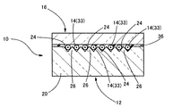
先ず、図1及び図2には、本発明に従う光ファイバアレイの一実施形態が、その縦断面形態と横断面形態とにおいて、それぞれ概略的に示されている。それらの図から明らかなように、本実施形態の光ファイバアレイ10は、光ファイバ整列用基板12と、それに支持される複数(ここでは8本)の光ファイバ14と、それら複数の光ファイバ14を光ファイバ整列用基板12に押さえ付けるための押え部材として、かかる基板12上に配置された押え板16とを有して、構成されている。
【0028】
より具体的には、この光ファイバアレイ10を構成する光ファイバ整列用基板12は、図3乃至図5に示されるように、全体として、一定の厚さを有する矩形の板材からなっており、長さ方向の一方側の略半分の部分が、複数の光ファイバ14を支持する支持部18とされている一方、その他方側の残り部分が、それら複数の光ファイバ14を整列して配置せしめる整列部20とされている。なお、この光ファイバ整列用基板12は、光ファイバアレイ10が接続される、例えば、光合分波器(図示せず)等の光デバイスを与える材料と同一の材料、例えば、ガラス材料やシリコン材料等にて形成されており、それによって、そのような光合分波器等と同一の熱膨張率が確保されるようになっている。
【0029】
そして、かかる光ファイバ整列用基板12にあっては、支持部18の上面が、平坦な支持面22とされており、また、整列部20の上面における幅方向両端部を除いた中間部位には、断面V字形状を呈する複数(ここでは8個)の凹溝24が、光ファイバ整列用基板12の幅方向において互いに隣り合う並列形態をもって、かかる基板12の長さ方向に沿って真っ直ぐに連続して延びるように、形成されている。更に、それら各凹溝24は、後述するように、光ファイバ14の被覆部30が除去された先端部位が収容され得る大きさとされている。
【0030】
なお、ここでは、上述せる如く、光ファイバ整列用基板12が一定の厚さとされていることによって、支持部18の上面(支持面22)と整列部20の上面とが、同じ高さに位置せしめられるようになっており、以て、整列部20に設けられた複数の凹溝24の隣り合うもの同士の間に形成される山部26の頂部部位が、支持面22と同一の高さに位置せしめられて、支持面22から上方に突出せしめられないようになっている。
【0031】
そして、本実施形態では、特に、そのような光ファイバ整列用基板12における支持部18と整列部20との間に、整列部20に設けられた複数の凹溝24のそれぞれの底部から支持部18に向かって、上傾して延びる傾斜面形態を有する、従来品には見られない傾斜案内面28が、それぞれの凹溝24に対応して、一体的に形成されているのである。
【0032】
すなわち、この傾斜案内面28にあっては、各凹溝24における支持部18側の端部において、その一部部位を塞ぐようにして、凹溝24の底部から、凹溝24の深さと同一の高さとなるまで立ち上がり、最も低い位置に位置する、立上りの基部側部分において、各凹溝24の底部に連設せしめられる一方、最も高い位置に位置する、立上りの先端部分において、支持部18の支持面22に連設せしめられて、形成されているのである。
【0033】
かくして、本実施形態の光ファイバアレイ10を構成する光ファイバ整列用基板12にあっては、整列部20に設けられた複数の凹溝24のそれぞれの底部から支持部18の支持面に向かって上傾して延びる傾斜面、換言すれば、支持部18の支持面22における整列部20側の端縁部位から、整列部20の各凹溝24の底部に向かって下傾して延びる、下方に向かうに従って狭幅となる三角形状の傾斜面からなる傾斜案内面28が、複数の凹溝24に対して、それぞれ一つずつ対応して形成されている。また、それと共に、前述せる如く、複数の凹溝24の隣り合うもの同士の間に形成される山部26の頂部部位が、支持部18の支持面22と同一の高さに位置せしめられて、支持面22から上方に突出せしめられないようになっている。これらによって、かかる光ファイバ整列用基板12においては、従来品とは異なって、整列部20における支持部18側の端部に、各凹溝24の側面と山部26の端面とに角張ったエッジ部が何等形成されないようになっているのである。
【0034】
そして、図1及び図2に示されるように、かくの如き構造とされた光ファイバ整列用基板12の支持部18に対して、8本の光ファイバ14が支持されているのであるが、ここでは、それら各光ファイバ14が、支持部18の平坦な支持面22上に、それぞれの先端部位を整列部20に向かって延出せしめた状態で、水平に配置されている。
【0035】
すなわち、本実施形態においては、互いに間隔を開けつつ、並列して延びる4本の光ファイバ14が被覆部30にて一体的に被覆されてなるテープファイバ32の二つが、支持部18の支持面22上において、上下に重ね合わされ、且つ下側のテープファイバ32の隣り合う光ファイバ14同士の間に、上側のテープファイバ32の光ファイバ14が位置するように、光ファイバ整列用基板12の幅方向に所定寸法だけずらされて、配置されることにより、8本の光ファイバ14が、光ファイバ整列用基板12の幅方向に所定間隔をおいて並べられて、光ファイバ整列用基板12の長さ方向に真っ直ぐに延びるように位置せしめられつつ、支持部18に支持されている。
【0036】
また、かかる支持部18にて支持された二つのテープファイバ32,32は、それぞれの先端部位が、被覆部30が除去されて、裸ファイバ部33とされており、それによって、各光ファイバ14が、被覆部30が形成された部位において、支持部18にて支持せしめられる一方で、裸ファイバ部33において、光ファイバ整列用基板12の幅方向に所定間隔を開けて並列せしめられた状態で、整列部20に向かって延出せしめられているのである。
【0037】
そして、整列部20に向かって延出せしめられた各光ファイバ14の裸ファイバ部33が、整列部20と支持部18との間において、支持部18から整列部20に向かって下傾して延びる傾斜面形態をもって、整列部20の各凹溝24に対応して形成された各傾斜案内面28に沿って、下傾して延出せしめられるように、それら各傾斜案内面28に案内されつつ、各凹溝24内に、それぞれ、一本ずつ導かれて、収容せしめられている。また、それら各光ファイバ14の裸ファイバ部33の先端部分は、各凹溝24における傾斜案内面28側とは反対側の開口端から外方に延出せしめられている。
【0038】
これによって、光ファイバ整列用基板12の支持部18の支持面22上に支持された複数の光ファイバ14が、裸ファイバ部33において、複数の凹溝24の配列形態と同様に、光ファイバ整列用基板12の幅方向において互いに隣り合う並列形態をもって、かかる基板12の長さ方向に沿って真っ直ぐに延びるように、整列部20上で、整列せしめられているのである。
【0039】
なお、ここでは、各光ファイバ14の裸ファイバ部33が、傾斜案内面28に案内されつつ、各凹溝24内に収容せしめられて、整列せしめられた状態下で、傾斜案内面28に接触せしめられる場合には、各傾斜案内面28に対して面接触せしめられることとなるため、各光ファイバ14の裸ファイバ部33における傾斜案内面28との接触部分において、例えば、点接触や線接触によって生ずる応力集中が惹起されるようなことが、有利に防止され得るようになっているのである。
【0040】
一方、かくして複数の光ファイバ14が整列せしめられた整列部20上には、押え板16が配置されている。この押え板16は、光ファイバ整列用基板12と同じガラス材料やシリコン材料等からなる、かかる基板12よりも薄肉の矩形平板にて構成されており、整列部20に設けられた複数の凹溝24の上側開口部の全てを覆蓋し得る大きさを有している。また、かかる押え板16にあっては、特に、長さ方向の両端部の下側に位置する二つの下側角部のうちの一方の角部が、凸状湾曲面からなる湾曲角部34とされている。
【0041】
そして、そのような押え板16が、湾曲角部34を、整列部20と支持部18との間に設けられた複数の傾斜案内面28にそれぞれ対応位置させつつ、各光ファイバ14の裸ファイバ部33がそれぞれ収容された各凹溝24の上側開口部を全て覆蓋するようにして、整列部20上に載置されているのである。
【0042】
これによって、各凹溝24内に収容された各光ファイバ14の裸ファイバ部33が、押え板16の下面にて押さえ付けられて、かかる押え板16の下面と、各凹溝24の両側面との間で挟持され、以て、各光ファイバ14の変位が阻止されて、それらの整列状態が維持され得るようになっているのである。また、ここでは、特に、押え板16が整列部20上に配置された状態下で、押え板16の湾曲角部34が、各傾斜案内面28に対応位置せしめられているところから、各傾斜案内面28に案内されつつ、各凹溝24内に導かれる各光ファイバ14の裸ファイバ部33が、押え板16の、各傾斜案内面28に対応する端部の凹溝24側に位置する角部(湾曲角部34)と接触せしめられた際に、かかる角部に対して面接触せしめられることとなり、以て角張った角部と線接触せしめられる場合とは異なって、かかる湾曲角部34との接触部位において応力集中が生ぜしめられるようなことが、有利に防止され得るようになっているのである。
【0043】
なお、本実施形態の光ファイバアレイ10においては、前述せる如く、支持部18に支持された各光ファイバ14の裸ファイバ部33が、支持部18の支持面22よりも低い位置に底部が位置せしめられた各凹溝24内に、下傾して延びる各傾斜案内面28に案内されつつ、導かれるようになっているため、図1からも明らかなように、各光ファイバ14の裸ファイバ部33が、極めて緩やかなS字を描くように湾曲せしめられることとなるが、それら各光ファイバ14の裸ファイバ部33のそれぞれの湾曲部位の曲率半径:Rは、光ファイバ14の破断を防止する上で、可及的に大きくされていることが望ましい。そこで、ここでは、光ファイバ14における湾曲部位のそれぞれの曲率半径:Rが、20mm以上とされている。このように、かかる曲率半径:Rが20mm程度とされる場合には、例えば、下記式(1)に示される光ファイバ14の破断確率と曲率半径の理論式に従えば、30年経過したときの光ファイバ14の裸ファイバ部33の破断確率が1%程度となるのである。
【0044】
【数1】
【0045】
一方、光ファイバ14の裸ファイバ部33における上記湾曲部位の曲率半径:Rは、傾斜案内面28の傾斜角度:θと、各凹溝24の長さ:L1と、押え板16の下面における湾曲角部34の湾曲面を除いた平坦面の長さ:L2とに左右される。このため、それら傾斜案内面28の傾斜角度:θと、各凹溝24の長さ:L1と、押え板16の下面における湾曲角部34の湾曲面を除いた平坦面の長さ:L2は、一般に、支持部18の支持面22上に支持されるテープファイバ32,32のそれぞれにおける厚さ方向の中心から支持面22までの距離:T1,T2に基づいて、求められるところではあるものの、それらの値(θ、L1、L2)は、光ファイバ14の裸ファイバ部33における湾曲部位の曲率半径:Rが、上記した式(1)にて示される光ファイバ14の破断確率と曲率半径の理論式により得られる最小曲率半径以上となるように、決定されることとなるのである。なお、因みに、本実施形態では、T1=0.16mmで、T2=0.48mmであるため、θ=10°、L1=7.5mm、L2=3.5mmとされている。これらの値や、光ファイバ14の裸ファイバ部33における湾曲部位の曲率半径:Rが、例示の値に、何等限定されるものでないことは、勿論である。
【0046】
而して、本実施形態では、上述の如くして、光ファイバ整列用基板12上に、複数の光ファイバ14が整列状態で配置されると共に、それら各光ファイバ14を押さえ付けて、それらの整列状態を維持させる押え板16が載置された状態下で、公知の接着剤からなる接着剤層36が、光ファイバ整列用基板12の整列部20における各凹溝24内の隙間に充填されると共に、かかる基板12上に位置せしめられた各光ファイバ14の裸ファイバ部33の全てを覆うように形成されており、以て、光ファイバ整列用基板12と押え板16とに対して、複数の光ファイバ14が固着されて、光ファイバアレイ10が、構成されているのである。
【0047】
そして、かかる光ファイバアレイ10にあっては、例えば、導波路が内部に設けられた光合分波器等に取り付けられて、各凹溝24から外部に延出せしめられた光ファイバ14の裸ファイバ部33の先端部が、導波路等に接続されるようになっているのである。
【0048】
このように、本実施形態の光ファイバアレイ10にあっては、光ファイバ整列用基板12において、複数の凹溝24の隣り合うもの同士の間に形成される山部26の頂部部位が、支持部18の支持面22から上方に突出しないように構成されていると共に、支持部18の支持面22から各凹溝24の底部に向かって下傾する傾斜案内面28が、各凹溝24に対応して形成されていることによって、整列部20における支持部18側の端部に、各凹溝24の側面と山部26の端面とにて形成される、角張ったエッジ部が何等存在せしめられないようになっているところから、支持部18に支持された複数の光ファイバ14のそれぞれの裸ファイバ部33を各凹溝24内に収容せしめる際に、多少の位置ズレが生じていたり、或いは接着剤層36の硬化収縮等が発生したりしても、各光ファイバ14の裸ファイバ部33が、角張ったエッジ部に接触せしめられることが、有利に皆無ならしめられ得るのであり、それによって、そのようなエッジ部との接触に起因する各光ファイバ14の裸ファイバ部33での応力集中の発生が、効果的に回避され得るのである。
【0049】
しかも、かかる光ファイバアレイ10においては、各光ファイバ14の裸ファイバ部33における傾斜案内面28との接触部分で、例えば、点接触や線接触により生ずる応力集中が惹起されるようなことも、有利に防止され得るようになっているのである。
【0050】
従って、このような本実施形態に係る光ファイバアレイ10にあっては、全ての光ファイバ14において、裸ファイバ部33での応力集中に起因する伝送損失の増大や損傷、断線等の発生が、効果的に防止され得るのであり、その結果として、良好な使用状態の維持と使用寿命の延命化とが、極めて有利に実現せしめられ得ることとなるのである。
【0051】
また、かかる光ファイバアレイ10においては、押え板16の、各傾斜案内面28に対応する端部の凹溝24側に位置する角部が、湾曲面からなる湾曲角部34とされて、各光ファイバ14の裸ファイバ部33が、かかる湾曲角部34との接触によって応力集中が生ずるようなことも阻止され得るようになっており、これによっても、裸ファイバ部33での応力集中に起因する伝送損失の増大や損傷、断線等の発生が、効果的に防止され得るのである。
【0052】
さらに、本実施形態の光ファイバアレイ10にあっては、支持部18の支持面22と整列部20の上面とが同じ高さ位置となるように、一定の厚さとされた光ファイバ整列用基板12の整列部20上に、薄肉平板状の押え板16が配置されて、構成されているところから、例えば、支持部18と整列部20との間に、整列部20を支持部18よりも厚肉と為す段差面が設けられて、整列部20の上面が、支持部18の支持面22より高い位置に位置せしめられるように構成された従来品に対して、例えば、支持部18を同一厚さとした場合に、光ファイバ整列用基板12、ひいては光ファイバアレイ10全体の厚さを有利に薄く為すことが出来、以て光ファイバアレイ10全体の小型化が、有利に達成され得るのである。
【0053】
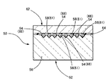
次に、図6には、前記実施形態とは、光ファイバ整列用基板12における支持部18の構造が異なる別の例が、示されている。なお、この図6においては、前記実施形態と同様な構造とされた部材及び部位について、前記実施形態を示す図1乃至図5と同一の符号を付すことにより、その詳細な説明は、省略した。
【0054】
すなわち、本実施形態に係る光ファイバアレイ40にあっては、光ファイバ整列用基板12における支持部18の支持面42が、支持部18と整列部20との間に形成された複数の傾斜案内面28のそれぞれと同一の傾斜角度をもって、それら各傾斜案内面28に向かって下傾する傾斜面にて構成されている。そして、それによって、各光ファイバ14の裸ファイバ部33が、支持面42に沿って、各傾斜案内面28に向かって下傾して、延出せしめられるように、各光ファイバ14が、支持面42上に支持されているのである。
【0055】
このような構造とされた本実施形態では、傾斜案内面28に向かって下傾して延びる各光ファイバ14の裸ファイバ部33が、傾斜案内面28に案内されて、凹溝24内に導き入れられる部分で、凹溝24の両側側面の底部側部分に接触せしめられることにより、下傾状態から水平状態となるように湾曲せしめられ、それによって、かかる裸ファイバ部33の湾曲部位において、水平状態から下傾状態に復元しようとする作用力(反力)が発揮せしめられこととなる。そして、そのような作用力によって、各光ファイバ14の裸ファイバ部33における凹溝24内に収容された部分が、凹溝24の底部側の側面に押し付けられて、複数の光ファイバ14の全ての裸ファイバ部33が、各凹溝24内において、その底部側の側面に対して確実に接触せしめられつつ、かかる側面に沿って延びるように収容せしめられ得るのであり、その結果として、複数の光ファイバ14の全てが、上下方向や左右方向等に偏心せしめられることのない優れた位置精度をもって、整然と整列せしめられ得ることとなるのである。
【0056】
また、勿論、本実施形態においても、支持面22から各凹溝24の底部に向かって下傾する傾斜案内面28が設けられていることによって、前記実施形態と同様な作用・効果が有効に享受され得るのである。
【0057】
なお、本実施形態では、傾斜案内面28に向かって下傾する傾斜面からなる支持面42の傾斜角度が、傾斜案内面28と同一の角度とされていたが、この傾斜面からなる支持面42は、傾斜案内面28に向かって下傾する形態を有するのであれば、その傾斜角度が、何等これに限定されるものではないのである。
【0058】
以上、本発明の具体的な構成について詳述してきたが、これはあくまでも例示に過ぎないのであって、本発明は、上記の記載によって、何等の制約をも受けるものではない。
【0059】
例えば、前記実施形態では、光ファイバ整列用基板12の整列部20に設けられた凹溝24が、断面V字形状を有して構成されていたが、かかる凹溝24は、光ファイバ14の裸ファイバ部33が収容され得る構造を有しておれば、その形状が、特に限定されるものではなく、例えば、U字形状や、矩形形状、或いは円弧形状において、構成しても良いのである。
【0060】
また、光ファイバ整列用基板12の支持部18に支持されて、かかる基板12と押え板16とに固着される光ファイバ14の本数も、前記実施形態に示されるものに決して限定されるものではなく、更に、光ファイバ整列用基板12の整列部20に設けられる凹溝24の数も、支持部18に支持される光ファイバ14の本数に応じて、適宜に変更され得るものであることは、言うまでもないところである。また、テープファイバ32を支持部18に支持させる場合にも、かかるテープファイバ32を三つ以上重ね合わせても良いのであり、或いは何等重ね合わせることなく、一つだけを支持させることも、勿論可能である。
【0061】
更にまた、前記実施形態とは異なって、支持部18の上面の一部のみにて、支持面22,42が構成されていても、何等差し支えないのである。
【0062】
また、前記実施形態では、押え板16の長さ方向両端部に位置する二つの下側角部のうちの一方が、湾曲面からなる湾曲角部34とされて、かかる湾曲角部34が、光ファイバ整列用基板12に設けられた傾斜案内面28に対応位置するように、押え板16が、光ファイバ整列用基板12の整列部20上に配置されるようになっていたが、押え板16が光ファイバ整列用基板12の整列部20上に配置された状態下で、傾斜案内面28に対応位置せしめられる、押え板16の一方の下側角部を、例えば、湾曲角部34に代えて、面取りが施された面取り角部と為しても良いのである。これによっても、かかる押え板16の下側角部を湾曲角部34として構成した場合に得られる作用・効果と同様な作用・効果が、有効に享受され得るのである。
【0063】
さらに、支持面22,42と各傾斜案内面28とにて角部が形成される場合には、その角部を湾曲面からなる湾曲角部や面取りが施されてなる面取り角部としても良いのであり、また、それと同様に、各傾斜案内面28と各凹溝24の底部とにて角部が形成される場合にも、かかる角部を湾曲角部や面取り角部としても良いのである。これによって、各光ファイバ14の裸ファイバ33での応力集中が、より有利に解消され得ることとなるのである。
【0064】
更にまた、前記実施形態では、凹溝24の底部から支持部18に向かって立ち上がる傾斜案内面28の最大高さが、凹溝24の深さと同一の高さとされていたが、かかる傾斜案内面28の最大高さを、凹溝24の深さよりも高い高さと為しても良いのである。
【0065】
その他、一々列挙はしないが、本発明は、当業者の知識に基づいて種々なる変更、修正、改良等を加えた態様において実施され得るものであり、また、そのような実施態様が、本発明の趣旨を逸脱しない限り、何れも、本発明の範囲内に含まれるものであることは、言うまでもないところである。
【0066】
【発明の効果】
以上の説明からも明らかなように、本発明に従う光ファイバ整列用基板にあっては、光ファイバが支持部に支持せしめられた状態下で、光ファイバの被覆部が除去された先端部位が角張ったエッジ部と接触せしめられることにより、かかる先端部位に応力集中が生ぜしめられることは勿論、光ファイバの先端部位の傾斜案内面との接触によって、光ファイバの先端部位に応力集中が惹起されるようなことも、有利に解消され得るのであり、以て、そのような応力集中に起因する光ファイバの伝送損失の増大や損傷、断線等の発生が、効果的に防止され得ることとなるのである。
【0067】
また、本発明に従う光ファイバアレイにおいては、光ファイバの被覆部が除去された先端部位での応力集中の発生が有利に解消され得て、そのような応力集中に起因する光ファイバの伝送損失の増大や損傷、断線等の発生が、極めて効果的に防止され得ることとなるのであり、その結果として、良好な使用状態の維持と使用寿命の延命化とが、極めて有利に実現せしめられ得ることとなるのである。
【図面の簡単な説明】
【図1】本発明に従う構造を有する光ファイバアレイの一例を示す縦断面説明図である。
【図2】図1におけるII−II断面説明図である。
【図3】図1に示された光ファイバアレイを構成する光ファイバ整列用基板の上面説明図である。
【図4】図3におけるIV−IV断面説明図である。
【図5】図3におけるV矢視説明図である。
【図6】本発明に従う構造を有する光ファイバアレイの別の例を示す図1に対応する図である。
【図7】従来の光ファイバアレイを示す図1に対応する図である。
【図8】図7におけるVIII−VIII断面説明図である。
【図9】図7に示された従来の光ファイバアレイを構成する光ファイバ整列用基板を説明するための図7におけるIX矢視説明図である。
【符号の説明】
10,40 光ファイバアレイ 12 光ファイバ整列用基板
14 光ファイバ 16 押え板
18 支持部 20 整列部
22,42 支持面 24 凹溝
28 傾斜案内面 30 被覆部
33 裸ファイバ部 34 湾曲角部[0001]
【Technical field】
The present invention relates to an optical fiber alignment substrate and an optical fiber array, and more particularly, to an improved optical fiber alignment substrate for aligning and fixing a plurality of optical fibers and an optical fiber array configured using the same. The structure.
[0002]
[Background Art]
In recent years, an optical fiber communication system using an optical fiber, which is considered as one of the lowest-loss and large-capacity transmission lines in information transmission lines, as a communication cable has received a great deal of attention in the information communication field. Active development is underway. In such an optical fiber communication system, an optical fiber array is generally used as a kind of connecting component for connecting an optical fiber to an optical multiplexer / demultiplexer or the like in which an optical waveguide is provided. is there.
[0003]
By the way, as shown in FIGS. 7 to 9, for example, the conventional optical fiber array 50 is configured such that one portion in the length direction is thicker in the middle portion in the length direction than the other portion. It has an optical fiber alignment substrate 52 made of a stepped flat plate provided with a step surface 51 to be formed. In the optical fiber alignment substrate 52, the thin portion is a support portion 53 having a flat upper surface, while the thick portion is provided with a plurality of V-shaped concave grooves 54 on the upper surface. Are aligned portions 56 formed in a side-by-side state adjacent to each other. The plurality of optical fibers 58 are supported by the support portion 53 of the optical fiber alignment substrate 52 at the portion where the coating portion 60 is formed, and the bare fiber portion 61 is formed of a distal end portion from which the coating portion 60 is removed. In the above, each of the optical fibers 58 is arranged such that the bare fiber portion 61 of each of the optical fibers 58 is inserted into the plurality of grooves 54 of the alignment portion 56. It is held down by a holding member 62 arranged to cover. In such a state, the plurality of optical fibers 58 are embedded in the adhesive layer 64 formed between the holding member 62 and the optical fiber alignment substrate 52 so that the holding members 62 and the optical fiber alignment substrate 52.
[0004]
Thus, in the conventional optical fiber array, the plurality of optical fibers 58 are fixed while being aligned at a fixed interval in the width direction of the optical fiber alignment substrate 52, and thus the plurality of optical fibers 58 are fixed. Each of the optical fibers 58 is configured to be reliably connected to an optical waveguide or the like of an optical multiplexer / demultiplexer.
[0005]
However, in the optical fiber alignment substrate 52 constituting such a conventional optical fiber array, as is apparent from FIG. 9, the alignment section 56 is disposed between the support section 53 and the alignment section 56 by the support section 53. Is also thick, in other words, since the step surface 51 for positioning the upper surface of the alignment portion 56 at a position higher than the upper surface of the support portion 53 is provided, such a step surface 51 and the alignment portion 56 are provided. An angular edge 70 was inevitably formed on each of the side surfaces 68 of the plurality of grooves 54 provided, and the existence of such an edge 70 caused a number of problems. Had been raised.
[0006]
That is, when the bare fiber portions 61 of the optical fibers 58 are accommodated in the concave grooves 54 of the alignment portion 56 of the optical fiber alignment substrate 52, for example, the bare fiber portions 61 When the fiber portion 61 is in contact with the angular edge portion 70 formed by the step surface 51 and the side surface 68 of each groove 54 and is positioned in a slightly bent state, the optical fiber 58 The stress is concentrated on the contact portion of the bare fiber portion 61 with the edge portion 70, which may cause an increase in transmission loss, damage to the optical fiber, and even breakage of the optical fiber. Even if the bare fiber portion 61 of each optical fiber 58 does not bend due to the displacement or the like, the bare fiber portion 61 of each optical fiber 58 contacts the edge portion 70. When the optical fiber 58 is tightened, the coating portion 60 of the optical fiber 58 is removed by the curing and shrinkage of the adhesive layer 64 that fixes each optical fiber 58 to the optical fiber alignment substrate 52 and the expansion and contraction due to a temperature cycle. In this case, stress concentration is caused at the contact portion with the edge portion 70, and as a result, the same problem as described above may occur.
[0007]
Under such circumstances, in order to solve the above-described problem, the step surface formed between the support portion and the alignment portion is formed as a convex curved surface, and the length of the edge portion is increased. An optical fiber alignment substrate (e.g., such as, for example, a method of increasing the length of a contact portion of an optical fiber with an edge portion of a bare fiber portion, and thereby reducing stress concentration at the contact portion of the optical fiber with the edge portion of the optical fiber. By arranging the optical fiber such that a portion of the optical fiber accommodated in each groove of the alignment portion, which is positioned at the end of the support groove side, in each of the grooves rises. An optical fiber connector configured such that a bare fiber portion and an edge portion of a fiber do not come into contact with each other (for example, Patent Document 2) has been proposed.
[0008]
However, in these structures, the optical fiber alignment substrate still has an angular edge, so that, for example, the processing accuracy of the concave groove, the dimensional accuracy in the bare fiber portion of the optical fiber, or the mounting accuracy is low. In such a case, the bare fiber portion of the optical fiber may be brought into contact with the edge portion, and in such a case, stress concentration is eventually caused at the contact portion with the edge portion of the optical fiber. It was not a fundamental solution at all.
[0009]
[Patent Document 1]
JP 2000-275478 A
[Patent Document 2]
JP-A-2002-131580
[0010]
[Solution]
Here, the present invention has been made in view of the above-mentioned circumstances, and a problem to be solved is to contact an end portion (bare fiber portion) where the coating portion of the optical fiber has been removed. By completely eliminating the angular edges formed, the occurrence of stress concentration at the tip portion of the optical fiber is eliminated, thereby increasing the transmission loss, damage, disconnection, etc. of the optical fiber due to such stress concentration. It is an object of the present invention to provide an optical fiber alignment substrate improved so as to advantageously prevent the occurrence of an optical fiber array, and an optical fiber array including such an optical fiber alignment substrate.
[0011]
[Solution]
According to the present invention, in order to solve the problem relating to the optical fiber alignment substrate among the technical problems, (a) a support portion for supporting a plurality of optical fibers; and (b) a plurality of concave portions. The grooves are formed in a side-by-side state adjacent to each other, and the plurality of optical fibers supported by the support portion are provided in the plurality of concave grooves one by one at the distal end portion where the coating portion is removed. (C) between the support portion and the alignment portion, from the bottom of each of the plurality of concave grooves formed in the alignment portion, wherein the alignment portion aligns the plurality of optical fibers by being accommodated. A plurality of optical fibers supported by the supporting portion are provided so as to extend toward the support portion with an inclined surface form rising up to a height equal to or greater than the depth of the concave portion, thereby closing the concave portion. In each The serial coating portion is the tip portion which is removed, the optical fiber aligning substrate, characterized in that integrally provided with an inclined guide surface for guiding each into each groove, is to its gist.
[0012]
That is, in the optical fiber alignment substrate according to the present invention, the inclined guide surface is provided between the support portion for supporting the plurality of optical fibers and the alignment portion having the plurality of grooves. From the bottom of the groove to the support part, in other words, from the support part, extending downward from the support part toward the bottom of each groove, and integrally formed, The bottom of each of the plurality of grooves is located at a position lower than the support portion, and such an inclined guide surface rises and extends until the height is equal to or greater than the depth of the groove. Therefore, the maximum height of the inclined guide surface integrated with the support portion at the highest portion is set to be equal to or greater than the depth of the concave groove.
[0013]
Therefore, in the optical fiber alignment substrate according to the present invention, the upper surface of the support portion is positioned at the same height as or higher than the upper surface of the alignment portion, whereby Unlike the conventional product in which a step surface for positioning the upper surface of the alignment portion at a position higher than the upper surface of the support portion is provided between the portion and the alignment portion, such a step surface and the side surface of each concave groove are provided. The formation of a sharp edge portion can be advantageously avoided, and such an edge portion can be completely eliminated.
[0014]
Moreover, in such an optical fiber alignment substrate, between the support portion and the alignment portion, the support portion extends downward from the support portion toward each bottom of the plurality of concave grooves provided in the alignment portion. The formed inclined guide surface allows each of the plurality of optical fibers supported by the supporting portion to be guided into the respective recessed groove, so that the leading end portions of the optical fibers from which the coating portions have been removed are guided into the respective grooves. The portion guided by the inclined guide surface in the tip portion of the fiber is brought into surface contact with the inclined guide surface.
[0015]
Therefore, in such an optical fiber alignment substrate according to the present invention, in a state where the optical fiber is supported by the support portion, the distal end portion where the coating portion of the optical fiber is removed comes into contact with the angular edge portion. Due to the squeezing, not only the stress concentration is generated at the distal end portion, but also it is advantageous that the stress concentration is caused at the distal end portion of the optical fiber by the contact of the distal end portion of the optical fiber with the inclined guide surface. Therefore, an increase in transmission loss of the optical fiber, damage, disconnection, and the like due to such stress concentration can be effectively prevented.
[0016]
According to one preferred embodiment of such an optical fiber alignment substrate according to the present invention, the support portion is configured to have a flat support surface, and the plurality of optical fibers are provided on the support surface. It is comprised so that it may be supported horizontally by.
[0017]
In the case of employing such a configuration, for example, if the thickness of the conventional optical fiber alignment substrate in which the alignment portion is thicker than the support portion and the thickness of the support portion are the same, such a conventional product can be obtained. In comparison, the overall thickness can be reduced, whereby the miniaturization of the entire substrate can be advantageously achieved.
[0018]
Further, according to another advantageous aspect of the optical fiber alignment substrate according to the present invention, the support portion is configured to have a support surface including an inclined surface inclined downward toward the inclined guide surface. Then, the plurality of optical fibers are configured to be supported by the support surface in a state where the distal end portion from which the coating portion has been removed is inclined down along the support surface.
[0019]
In the case where such a configuration is adopted, the distal end portion of the optical fiber, from which the coating portion has been removed, which extends downward and inclines along the support surface, is placed in each of the concave grooves. By contacting the bottom and the side of the bottom of each groove at the end on the side of the inclined guide surface in the groove, an action force for bending the tip of the optical fiber upward is exerted on the tip of the optical fiber. As a result, the distal end portion of the optical fiber is curved. Then, thereby, a reaction force against the acting force is generated at the distal end portion of the optical fiber positioned in the end on the inclined guide surface side in each of the concave grooves, so that the curved optical fiber is The tip portion is pressed against the bottom of each groove and the side surface on the bottom side by this reaction force.
[0020]
Therefore, in the optical fiber alignment substrate having the above-described configuration, all of the plurality of optical fibers are accommodated in each of the concave grooves in a state where the optical fibers are securely brought into contact with the side surface and the bottom surface. It can be positioned, so that all optical fibers can be aligned neatly with excellent positioning accuracy without being decentered.
[0021]
According to the present invention, in order to solve the technical problem related to the optical fiber array, a plurality of optical fibers are supported by the supporting portion with respect to the characteristic optical fiber alignment substrate as described above. In addition, at the tip portion where the covering portion is removed, each of the recesses is arranged while being accommodated one by one in the plurality of recesses in the alignment portion, while covering the recesses. With a pressing member that presses the distal end portions of the optical fibers housed in the grooves, under the state where the distal end portions of the plurality of optical fibers are pressed down, the pressing member and the optical fiber alignment substrate are An optical fiber array characterized in that the plurality of optical fibers are fixed to each other is also a gist of the present invention.
[0022]
In short, in the optical fiber array according to the present invention, the upper surface of the supporting portion supporting the plurality of optical fibers is located at the same height or higher than the upper surface of the alignment portion provided with the plurality of concave grooves. An optical fiber alignment substrate, which is integrally formed with an inclined guide surface rising and extending to a height equal to or greater than the depth of each groove in the alignment portion, between the support portion and the alignment portion. The optical fiber alignment substrate has such a structure, so that the effect obtained by having such a structure can be effectively enjoyed.
[0023]
Therefore, in such an optical fiber array according to the present invention, the occurrence of stress concentration at the distal end portion where the coating portion of the optical fiber has been removed can be advantageously eliminated, and the optical density caused by such stress concentration can be reduced. The increase in the transmission loss of the fiber, the damage, the occurrence of disconnection, etc. can be prevented very effectively. As a result, the maintenance of a good use state and the extension of the service life are extremely advantageous. It can be realized.
[0024]
According to one preferred aspect of such an optical fiber array according to the present invention, the pressing member includes the plurality of concave portions at the end corresponding to the inclined guide surface provided on the optical fiber alignment substrate. The corner located on the groove side is a chamfered chamfered corner or a curved corner formed of a convex curved surface.
[0025]
According to such a configuration, the distal end portion of the optical fiber from which the coating portion has been removed is brought into contact with the corner portion of the holding member located on the side of the plurality of grooves provided in the alignment portion of the optical fiber alignment substrate. As a result, the occurrence of stress concentration at the distal end portion of the optical fiber can be advantageously eliminated, and as a result, the increase in transmission loss, damage, disconnection, etc. of the optical fiber can be further reduced. Can be prevented.
[0026]
BEST MODE FOR CARRYING OUT THE INVENTION
Hereinafter, in order to clarify the present invention more specifically, configurations of an optical fiber alignment substrate and an optical fiber array according to the present invention will be described in detail with reference to the drawings.
[0027]
First, FIG. 1 and FIG. 2 schematically show an embodiment of an optical fiber array according to the present invention in a longitudinal sectional form and a transverse sectional form, respectively. As is apparent from those figures, the optical fiber array 10 of the present embodiment includes an optical fiber alignment substrate 12, a plurality of (eight in this case) optical fibers 14 supported by the substrate, and a plurality of the optical fibers 14 And a pressing plate 16 disposed on the optical fiber alignment substrate 12 as a pressing member.
[0028]
More specifically, as shown in FIGS. 3 to 5, the optical fiber alignment substrate 12 constituting the optical fiber array 10 is made of a rectangular plate material having a certain thickness as a whole, A substantially half portion on one side in the length direction is a supporting portion 18 for supporting the plurality of optical fibers 14, while the remaining portion on the other side allows the plurality of optical fibers 14 to be aligned and arranged. The alignment unit 20 is provided. The optical fiber alignment substrate 12 is made of the same material as an optical device such as an optical multiplexer / demultiplexer (not shown) to which the optical fiber array 10 is connected, such as a glass material or a silicon material. And the like, whereby the same coefficient of thermal expansion as that of such an optical multiplexer / demultiplexer or the like is ensured.
[0029]
In the optical fiber alignment substrate 12, the upper surface of the support portion 18 is a flat support surface 22, and the upper surface of the alignment portion 20 has an intermediate portion excluding both ends in the width direction. A plurality of (eight in this case) concave grooves 24 having a V-shaped cross section are formed in a parallel form adjacent to each other in the width direction of the optical fiber alignment substrate 12 and are continuously formed straight along the length direction of the substrate 12. It is formed so as to extend. Further, as described later, each of the concave grooves 24 has a size capable of accommodating the distal end portion of the optical fiber 14 from which the covering portion 30 has been removed.
[0030]
Here, as described above, since the optical fiber alignment substrate 12 has a constant thickness, the upper surface of the support portion 18 (support surface 22) and the upper surface of the alignment portion 20 are positioned at the same height. As a result, the top portion of the peak portion 26 formed between adjacent ones of the plurality of concave grooves 24 provided in the alignment portion 20 has the same height as the support surface 22. , So as not to protrude upward from the support surface 22.
[0031]
In the present embodiment, in particular, between the support portion 18 and the alignment portion 20 in such an optical fiber alignment substrate 12, the support portion extends from the bottom of each of the plurality of grooves 24 provided in the alignment portion 20. An inclined guide surface 28 which has an inclined surface form extending upward toward 18 and which is not seen in conventional products is integrally formed corresponding to each groove 24.
[0032]
That is, in the inclined guide surface 28, at the end of each groove 24 on the side of the support portion 18, a part of the groove is covered with the same depth as the depth of the groove 24 from the bottom of the groove 24. At the base portion of the rising edge, which is located at the lowest position, at the bottom of each groove 24, and at the tip portion of the rising edge, which is located at the highest position, the supporting portion 18 is provided. Is formed so as to be continuously provided on the support surface 22.
[0033]
Thus, in the optical fiber alignment substrate 12 constituting the optical fiber array 10 of the present embodiment, from the bottom of each of the plurality of grooves 24 provided in the alignment section 20 toward the support surface of the support section 18. The inclined surface extending upward, in other words, extending downward from the edge portion of the support surface 22 of the support portion 18 on the alignment portion 20 side toward the bottom of each concave groove 24 of the alignment portion 20. An inclined guide surface 28 formed of a triangular inclined surface that becomes narrower as going toward is formed for each of the plurality of concave grooves 24, one by one. At the same time, as described above, the top portion of the peak portion 26 formed between adjacent ones of the plurality of concave grooves 24 is positioned at the same height as the support surface 22 of the support portion 18. , From the support surface 22. Thus, in the optical fiber alignment substrate 12, unlike the conventional product, the edge of the alignment portion 20 on the side of the support portion 18 is provided with an angular edge formed on the side surface of each groove 24 and the end surface of the peak portion 26. No part is formed.
[0034]
As shown in FIG. 1 and FIG. 2, eight optical fibers 14 are supported by the support portion 18 of the optical fiber alignment substrate 12 having such a structure. Here, each of the optical fibers 14 is horizontally arranged on the flat support surface 22 of the support portion 18 with the respective distal end portions extending toward the alignment portion 20.
[0035]
That is, in the present embodiment, two of the tape fibers 32 in which four optical fibers 14 extending in parallel and extending in parallel while being spaced apart from each other are integrally covered with the covering portion 30 are formed on the supporting surface of the supporting portion 18. 22, the width of the optical fiber alignment substrate 12 is set such that the optical fiber 14 of the upper tape fiber 32 is positioned between the adjacent optical fibers 14 of the lower tape fiber 32. The eight optical fibers 14 are arranged at predetermined intervals in the width direction of the optical fiber alignment substrate 12 by being shifted by a predetermined dimension in the direction. It is supported by the support portion 18 while being positioned so as to extend straight in the vertical direction.
[0036]
Further, the two tape fibers 32, 32 supported by the support portion 18 have their respective distal end portions formed as bare fiber portions 33 with the covering portion 30 removed, whereby each optical fiber 14 Is supported by the support portion 18 at the portion where the coating portion 30 is formed, while the bare fiber portion 33 is arranged in parallel at a predetermined interval in the width direction of the optical fiber alignment substrate 12. , Extending toward the alignment section 20.
[0037]
Then, the bare fiber portion 33 of each optical fiber 14 extended toward the alignment portion 20 is inclined downward from the support portion 18 toward the alignment portion 20 between the alignment portion 20 and the support portion 18. Each of the inclined guide surfaces 28 is guided by the respective inclined guide surfaces 28 so as to extend downward along the respective inclined guide surfaces 28 formed corresponding to the respective concave grooves 24 of the alignment portion 20 with the extended inclined surface form. In addition, each of the grooves 24 is guided one by one and accommodated therein. Further, the distal end portion of the bare fiber portion 33 of each optical fiber 14 is extended outward from the opening end of each concave groove 24 opposite to the inclined guide surface 28 side.
[0038]
As a result, the plurality of optical fibers 14 supported on the support surface 22 of the support portion 18 of the optical fiber alignment board 12 are aligned with the optical fiber alignment in the bare fiber portion 33 in the same manner as the arrangement of the plurality of grooves 24. They are aligned on the alignment section 20 so as to extend straight along the length direction of the substrate 12 in a side-by-side configuration adjacent to each other in the width direction of the use substrate 12.
[0039]
Here, the bare fiber portion 33 of each optical fiber 14 is accommodated in each groove 24 while being guided by the inclined guide surface 28, and is brought into contact with the inclined guide surface 28 in an aligned state. When the optical fibers 14 are squeezed, they are brought into surface contact with the respective inclined guide surfaces 28, so that, for example, a point contact or a line contact at the contact portion of the bare fiber portion 33 of each optical fiber 14 with the inclined guide surface 28. This can advantageously prevent the stress concentrations caused by this.
[0040]
On the other hand, the holding plate 16 is disposed on the alignment section 20 in which the plurality of optical fibers 14 are aligned. The holding plate 16 is made of the same glass material or silicon material as the optical fiber alignment substrate 12, and is formed of a rectangular flat plate thinner than the substrate 12, and a plurality of concave grooves provided in the alignment portion 20. It is large enough to cover all of the 24 upper openings. In addition, in the pressing plate 16, in particular, one of the two lower corners located below both ends in the length direction has a curved corner 34 formed of a convex curved surface. It has been.
[0041]
Then, while such a holding plate 16 positions the curved corner portion 34 at each of the plurality of inclined guide surfaces 28 provided between the alignment portion 20 and the support portion 18, the bare fiber of each optical fiber 14 is formed. The part 33 is placed on the alignment part 20 so as to cover all the upper openings of the respective recessed grooves 24 accommodated therein.
[0042]
As a result, the bare fiber portions 33 of the optical fibers 14 housed in the respective grooves 24 are pressed by the lower surface of the holding plate 16, and the lower surface of the holding plate 16 and both side surfaces of the respective grooves 24. Thus, the optical fibers 14 are prevented from being displaced, and their aligned state can be maintained. In addition, here, in particular, in a state where the holding plate 16 is arranged on the alignment portion 20, the curved corners 34 of the holding plate 16 are positioned at positions corresponding to the respective inclined guide surfaces 28, and thus each of the inclined The bare fiber portion 33 of each optical fiber 14 guided into each groove 24 while being guided by the guide surface 28 is located on the groove 24 side of the end of the holding plate 16 corresponding to each inclined guide surface 28. When the corner portion (curved corner portion 34) is brought into contact with the corner portion, the corner portion is brought into surface contact with the corner portion, which is different from the case where the corner portion is brought into line contact with the sharp corner portion. It is possible to advantageously prevent the occurrence of stress concentrations at the site of contact with 34.
[0043]
In the optical fiber array 10 according to the present embodiment, as described above, the bare fiber portion 33 of each optical fiber 14 supported by the support portion 18 has the bottom located at a position lower than the support surface 22 of the support portion 18. As shown in FIG. 1, the bare fiber of each optical fiber 14 is guided into each recessed groove 24 while being guided by each inclined guide surface 28 extending downward. Although the portion 33 is curved so as to draw an extremely gentle S-shape, the radius of curvature R of each curved portion of the bare fiber portion 33 of each optical fiber 14 prevents the optical fiber 14 from breaking. In doing so, it is desirable that the size be as large as possible. Therefore, here, the radius of curvature R of each of the curved portions in the optical fiber 14 is set to 20 mm or more. As described above, when the radius of curvature: R is about 20 mm, for example, according to the theoretical formula of the fracture probability and the radius of curvature of the optical fiber 14 shown in the following equation (1), after 30 years, The probability of breakage of the bare fiber portion 33 of the optical fiber 14 is about 1%.
[0044]
(Equation 1)
[0045]
On the other hand, the radius of curvature: R of the curved portion in the bare fiber portion 33 of the optical fiber 14 is represented by the inclination angle of the inclined guide surface 28: θ and the length of each groove 24: L 1 And the length of the flat surface of the lower surface of the holding plate 16 excluding the curved surface of the curved corner portion 34: L Two Depends on. Therefore, the inclination angle of the inclined guide surface 28: θ and the length of each groove 24: L 1 And the length of the flat surface of the lower surface of the holding plate 16 excluding the curved surface of the curved corner portion 34: L Two Is generally the distance from the center in the thickness direction of each of the tape fibers 32, 32 supported on the support surface 22 of the support portion 18 to the support surface 22: T 1 , T Two , Based on their values (θ, L 1 , L Two ) Indicates that the radius of curvature R of the curved portion in the bare fiber portion 33 of the optical fiber 14 is equal to or larger than the minimum radius of curvature obtained by the theoretical formula of the fracture probability and the radius of curvature of the optical fiber 14 shown in the above equation (1). It is determined so that Note that, in the present embodiment, T 1 = 0.16mm, T Two = 0.48 mm, θ = 10 °, L 1 = 7.5mm, L Two = 3.5 mm. Needless to say, these values and the radius of curvature R of the curved portion in the bare fiber portion 33 of the optical fiber 14 are not limited to the exemplified values.
[0046]
Thus, in the present embodiment, as described above, the plurality of optical fibers 14 are arranged in an aligned state on the optical fiber alignment substrate 12, and each of the optical fibers 14 is pressed down to An adhesive layer 36 made of a known adhesive is filled in a gap in each groove 24 in the alignment section 20 of the optical fiber alignment substrate 12 with the holding plate 16 for maintaining the alignment state placed thereon. In addition, the optical fiber 14 is formed so as to cover all of the bare fiber portions 33 of the optical fibers 14 positioned on the substrate 12, so that the optical fiber alignment substrate 12 and the holding plate 16 The optical fiber array 10 is formed by fixing a plurality of optical fibers 14.
[0047]
In the optical fiber array 10, for example, a bare fiber of the optical fiber 14 attached to an optical multiplexer / demultiplexer or the like provided with a waveguide therein and extended outside from each groove 24. The tip of the portion 33 is connected to a waveguide or the like.
[0048]
As described above, in the optical fiber array 10 of the present embodiment, the top portion of the peak 26 formed between adjacent ones of the plurality of concave grooves 24 in the optical fiber alignment substrate 12 is supported. An inclined guide surface 28 that is configured not to protrude upward from the support surface 22 of the portion 18 and that is inclined downward from the support surface 22 of the support portion 18 toward the bottom of each groove 24 is formed on each groove 24. By being formed correspondingly, there is no angular edge formed by the side surface of each concave groove 24 and the end surface of the mountain portion 26 at the end of the alignment portion 20 on the support portion 18 side. When the respective bare fiber portions 33 of the plurality of optical fibers 14 supported by the support portion 18 are accommodated in the respective concave grooves 24, some misalignment occurs, Alternatively, the adhesive layer 36 Even if curing shrinkage or the like occurs, the bare fiber portion 33 of each optical fiber 14 can be advantageously prevented from being brought into contact with the angular edge portion, whereby such an edge can be prevented. The occurrence of stress concentration in the bare fiber portion 33 of each optical fiber 14 due to the contact with the portion can be effectively avoided.
[0049]
Moreover, in the optical fiber array 10, stress concentration caused by, for example, point contact or line contact is caused at the contact portion between the bare fiber portion 33 of each optical fiber 14 and the inclined guide surface 28. This can be advantageously prevented.
[0050]
Therefore, in the optical fiber array 10 according to the present embodiment, in all the optical fibers 14, an increase in transmission loss due to stress concentration in the bare fiber portion 33, damage, breakage, and the like occur. This can be effectively prevented, and as a result, maintenance of a good use state and extension of the service life can be realized very advantageously.
[0051]
In the optical fiber array 10, the corners of the holding plate 16 located on the side of the concave groove 24 at the ends corresponding to the respective inclined guide surfaces 28 are formed as curved corners 34 formed of curved surfaces. The bare fiber portion 33 of the optical fiber 14 can be prevented from causing stress concentration due to the contact with the curved corner portion 34, which also causes the stress concentration in the bare fiber portion 33. It is possible to effectively prevent an increase in transmission loss, damage, disconnection, and the like.
[0052]
Further, in the optical fiber array 10 of the present embodiment, the optical fiber alignment substrate having a constant thickness so that the support surface 22 of the support portion 18 and the upper surface of the alignment portion 20 are at the same height position. Since the thin flat plate-like holding plate 16 is disposed and configured on the twelve alignment portions 20, for example, the alignment portion 20 is disposed between the support portion 18 and the alignment portion 20 more than the support portion 18. For example, the support portion 18 is the same as a conventional product in which a step surface is formed to be thick and the upper surface of the alignment portion 20 is positioned higher than the support surface 22 of the support portion 18. When the thickness is set, the thickness of the optical fiber alignment substrate 12 and, consequently, the entire optical fiber array 10 can be advantageously reduced, whereby the miniaturization of the entire optical fiber array 10 can be advantageously achieved. .
[0053]
Next, FIG. 6 shows another example in which the structure of the support portion 18 in the optical fiber alignment substrate 12 is different from that of the above embodiment. In FIG. 6, members and parts having the same structure as in the above embodiment are denoted by the same reference numerals as those in FIGS. 1 to 5 showing the above embodiment, and detailed description thereof is omitted. .
[0054]
That is, in the optical fiber array 40 according to the present embodiment, the support surface 42 of the support portion 18 of the optical fiber alignment substrate 12 has a plurality of inclined guides formed between the support portion 18 and the alignment portion 20. Each of the surfaces 28 has the same inclination angle as that of each of the inclined surfaces, and the inclined surfaces are inclined downward toward the respective inclined guide surfaces 28. Then, each optical fiber 14 is supported so that the bare fiber portion 33 of each optical fiber 14 extends downward along the support surface 42 toward each inclined guide surface 28. It is supported on the surface 42.
[0055]
In the present embodiment having such a structure, the bare fiber portion 33 of each optical fiber 14 extending downward and inclined toward the inclined guide surface 28 is guided by the inclined guide surface 28 and guided into the concave groove 24. By being brought into contact with the bottom side portions of both side surfaces of the concave groove 24 at the portion to be inserted, the curved portion is curved from the downward inclined state to the horizontal state, and thereby, at the curved portion of the bare fiber portion 33, An acting force (reaction force) for restoring the state from the state to the downward inclined state is exerted. Then, by such an acting force, the portion of the bare fiber portion 33 of each optical fiber 14 housed in the concave groove 24 is pressed against the bottom side surface of the concave groove 24, and all of the plurality of optical fibers 14 Can be accommodated in each groove 24 so as to extend along the side surface while being securely brought into contact with the side surface on the bottom side thereof. As a result, a plurality of All of the optical fibers 14 can be aligned neatly with excellent positional accuracy without being decentered in the vertical direction, the horizontal direction, and the like.
[0056]
In addition, of course, also in the present embodiment, by providing the inclined guide surface 28 which is inclined downward from the support surface 22 toward the bottom of each concave groove 24, the same operation and effect as in the above embodiment can be effectively achieved. It can be enjoyed.
[0057]
In the present embodiment, the inclination angle of the support surface 42 formed of the inclined surface inclined downward toward the inclined guide surface 28 is set to the same angle as that of the inclined guide surface 28. However, the support surface formed of this inclined surface is used. As long as 42 has a form inclined downward toward the inclined guide surface 28, the inclination angle is not limited to this.
[0058]
Although the specific configuration of the present invention has been described in detail above, this is merely an example, and the present invention is not limited by the above description.
[0059]
For example, in the above-described embodiment, the concave groove 24 provided in the alignment section 20 of the optical fiber alignment substrate 12 is configured to have a V-shaped cross section. The shape is not particularly limited as long as it has a structure capable of accommodating the bare fiber portion 33. For example, the shape may be U-shaped, rectangular, or arc-shaped. .
[0060]
Further, the number of optical fibers 14 supported by the support portion 18 of the optical fiber alignment substrate 12 and fixed to the substrate 12 and the holding plate 16 is not limited to the number shown in the above embodiment. Further, the number of the grooves 24 provided in the alignment portion 20 of the optical fiber alignment substrate 12 can be appropriately changed according to the number of the optical fibers 14 supported by the support portion 18. It goes without saying. Also, when supporting the tape fiber 32 on the support portion 18, three or more such tape fibers 32 may be superimposed, or it is of course possible to support only one without superimposing at all. It is.
[0061]
Further, unlike the above-described embodiment, even if the support surfaces 22 and 42 are formed only by a part of the upper surface of the support portion 18, there is no problem.
[0062]
In the embodiment, one of the two lower corners located at both ends in the length direction of the holding plate 16 is a curved corner 34 formed of a curved surface, and the curved corner 34 is The holding plate 16 is arranged on the alignment section 20 of the optical fiber alignment board 12 so as to correspond to the inclined guide surface 28 provided on the optical fiber alignment board 12. Under the state where the optical fiber alignment substrate 16 is arranged on the alignment portion 20 of the optical fiber alignment substrate 12, one lower corner of the holding plate 16 that is positioned corresponding to the inclined guide surface 28 is, for example, a curved corner 34. Instead, it may be a chamfered corner with chamfering. With this configuration, the same operation and effect as those obtained when the lower corner portion of the holding plate 16 is formed as the curved corner portion 34 can be effectively enjoyed.
[0063]
Further, when a corner is formed by the support surfaces 22 and 42 and each inclined guide surface 28, the corner may be a curved corner formed of a curved surface or a chamfered corner formed by chamfering. Similarly, when a corner is formed between each inclined guide surface 28 and the bottom of each groove 24, the corner may be a curved corner or a chamfered corner. . As a result, the stress concentration in the bare fiber 33 of each optical fiber 14 can be more advantageously eliminated.
[0064]
Furthermore, in the above-described embodiment, the maximum height of the inclined guide surface 28 rising from the bottom of the concave groove 24 toward the support portion 18 is the same as the depth of the concave groove 24. The maximum height of 28 may be higher than the depth of the concave groove 24.
[0065]
In addition, although not enumerated one by one, the present invention can be embodied in modes in which various changes, modifications, improvements, and the like are added based on the knowledge of those skilled in the art. It goes without saying that all of them are included in the scope of the present invention unless departing from the spirit of the present invention.
[0066]
【The invention's effect】
As is clear from the above description, in the optical fiber alignment substrate according to the present invention, under the state where the optical fiber is supported by the support portion, the distal end portion where the coating portion of the optical fiber is removed is angular. By contacting the edge portion with the bent edge portion, not only the stress concentration is generated at the tip portion, but also the stress concentration is caused at the tip portion of the optical fiber by the contact of the tip portion of the optical fiber with the inclined guide surface. Such a situation can also be advantageously eliminated, so that an increase in transmission loss or damage of the optical fiber due to such stress concentration, occurrence of disconnection, etc. can be effectively prevented. is there.
[0067]
Further, in the optical fiber array according to the present invention, the occurrence of stress concentration at the tip portion where the coating portion of the optical fiber is removed can be advantageously eliminated, and the transmission loss of the optical fiber due to such stress concentration can be reduced. The occurrence of increase, damage, disconnection, etc. can be prevented very effectively, and as a result, maintenance of a good use state and extension of the service life can be realized very advantageously. It becomes.
[Brief description of the drawings]
FIG. 1 is an explanatory longitudinal sectional view showing an example of an optical fiber array having a structure according to the present invention.
FIG. 2 is an explanatory sectional view taken along the line II-II in FIG.
FIG. 3 is an explanatory top view of an optical fiber alignment substrate constituting the optical fiber array shown in FIG. 1;
FIG. 4 is an explanatory sectional view taken along the line IV-IV in FIG. 3;
FIG. 5 is an explanatory diagram viewed from an arrow V in FIG. 3;
FIG. 6 is a view corresponding to FIG. 1 and showing another example of an optical fiber array having a structure according to the present invention.
FIG. 7 is a view corresponding to FIG. 1 showing a conventional optical fiber array.
FIG. 8 is a sectional view taken along the line VIII-VIII in FIG. 7;
FIG. 9 is an explanatory view taken along the line IX in FIG. 7 for explaining an optical fiber alignment substrate constituting the conventional optical fiber array shown in FIG. 7;
[Explanation of symbols]
10,40 Optical fiber array 12 Optical fiber alignment substrate
14 Optical fiber 16 Holding plate
18 Support part 20 Alignment part
22, 42 support surface 24 concave groove
28 inclined guide surface 30 coating
33 Bare fiber part 34 Curved corner