JP2004202132A - Ultrasonograph - Google Patents
Ultrasonograph Download PDFInfo
- Publication number
- JP2004202132A JP2004202132A JP2002377976A JP2002377976A JP2004202132A JP 2004202132 A JP2004202132 A JP 2004202132A JP 2002377976 A JP2002377976 A JP 2002377976A JP 2002377976 A JP2002377976 A JP 2002377976A JP 2004202132 A JP2004202132 A JP 2004202132A
- Authority
- JP
- Japan
- Prior art keywords
- reference line
- axis
- target tissue
- region
- interest
- Prior art date
- Legal status (The legal status is an assumption and is not a legal conclusion. Google has not performed a legal analysis and makes no representation as to the accuracy of the status listed.)
- Granted
Links
- 230000005484 gravity Effects 0.000 claims description 38
- 238000002604 ultrasonography Methods 0.000 claims description 12
- 238000000034 method Methods 0.000 claims description 10
- 238000003745 diagnosis Methods 0.000 claims description 7
- 230000008569 process Effects 0.000 claims description 7
- 230000000149 penetrating effect Effects 0.000 claims description 3
- 238000000605 extraction Methods 0.000 abstract description 15
- 238000001514 detection method Methods 0.000 description 19
- 230000002861 ventricular Effects 0.000 description 13
- 238000012545 processing Methods 0.000 description 12
- 238000004364 calculation method Methods 0.000 description 11
- 238000010586 diagram Methods 0.000 description 10
- 238000006243 chemical reaction Methods 0.000 description 9
- 238000012937 correction Methods 0.000 description 6
- 239000000284 extract Substances 0.000 description 5
- 238000013519 translation Methods 0.000 description 5
- 238000004040 coloring Methods 0.000 description 4
- 238000005259 measurement Methods 0.000 description 4
- 210000005242 cardiac chamber Anatomy 0.000 description 3
- 230000006870 function Effects 0.000 description 3
- 210000001308 heart ventricle Anatomy 0.000 description 3
- 210000005240 left ventricle Anatomy 0.000 description 3
- 239000011159 matrix material Substances 0.000 description 3
- 230000015572 biosynthetic process Effects 0.000 description 2
- 230000009466 transformation Effects 0.000 description 2
- 230000006978 adaptation Effects 0.000 description 1
- 230000037237 body shape Effects 0.000 description 1
- 230000008859 change Effects 0.000 description 1
- 230000003205 diastolic effect Effects 0.000 description 1
- 230000000694 effects Effects 0.000 description 1
- 230000010354 integration Effects 0.000 description 1
- 238000007914 intraventricular administration Methods 0.000 description 1
- 230000008520 organization Effects 0.000 description 1
- 238000009877 rendering Methods 0.000 description 1
- 239000000523 sample Substances 0.000 description 1
Images


Classifications
-
- A—HUMAN NECESSITIES
- A61—MEDICAL OR VETERINARY SCIENCE; HYGIENE
- A61B—DIAGNOSIS; SURGERY; IDENTIFICATION
- A61B8/00—Diagnosis using ultrasonic, sonic or infrasonic waves
- A61B8/48—Diagnostic techniques
- A61B8/483—Diagnostic techniques involving the acquisition of a 3D volume of data
-
- A—HUMAN NECESSITIES
- A61—MEDICAL OR VETERINARY SCIENCE; HYGIENE
- A61B—DIAGNOSIS; SURGERY; IDENTIFICATION
- A61B8/00—Diagnosis using ultrasonic, sonic or infrasonic waves
-
- G—PHYSICS
- G01—MEASURING; TESTING
- G01S—RADIO DIRECTION-FINDING; RADIO NAVIGATION; DETERMINING DISTANCE OR VELOCITY BY USE OF RADIO WAVES; LOCATING OR PRESENCE-DETECTING BY USE OF THE REFLECTION OR RERADIATION OF RADIO WAVES; ANALOGOUS ARRANGEMENTS USING OTHER WAVES
- G01S15/00—Systems using the reflection or reradiation of acoustic waves, e.g. sonar systems
- G01S15/88—Sonar systems specially adapted for specific applications
- G01S15/89—Sonar systems specially adapted for specific applications for mapping or imaging
- G01S15/8906—Short-range imaging systems; Acoustic microscope systems using pulse-echo techniques
- G01S15/8993—Three dimensional imaging systems
-
- G—PHYSICS
- G01—MEASURING; TESTING
- G01S—RADIO DIRECTION-FINDING; RADIO NAVIGATION; DETERMINING DISTANCE OR VELOCITY BY USE OF RADIO WAVES; LOCATING OR PRESENCE-DETECTING BY USE OF THE REFLECTION OR RERADIATION OF RADIO WAVES; ANALOGOUS ARRANGEMENTS USING OTHER WAVES
- G01S7/00—Details of systems according to groups G01S13/00, G01S15/00, G01S17/00
- G01S7/52—Details of systems according to groups G01S13/00, G01S15/00, G01S17/00 of systems according to group G01S15/00
- G01S7/52017—Details of systems according to groups G01S13/00, G01S15/00, G01S17/00 of systems according to group G01S15/00 particularly adapted to short-range imaging
- G01S7/5205—Means for monitoring or calibrating
-
- Y—GENERAL TAGGING OF NEW TECHNOLOGICAL DEVELOPMENTS; GENERAL TAGGING OF CROSS-SECTIONAL TECHNOLOGIES SPANNING OVER SEVERAL SECTIONS OF THE IPC; TECHNICAL SUBJECTS COVERED BY FORMER USPC CROSS-REFERENCE ART COLLECTIONS [XRACs] AND DIGESTS
- Y10—TECHNICAL SUBJECTS COVERED BY FORMER USPC
- Y10S—TECHNICAL SUBJECTS COVERED BY FORMER USPC CROSS-REFERENCE ART COLLECTIONS [XRACs] AND DIGESTS
- Y10S128/00—Surgery
- Y10S128/916—Ultrasound 3-D imaging
Abstract
Description
【0001】
【発明の属する技術分野】
本発明は、超音波診断装置に関し、特に関心領域を設定できる三次元超音波診断装置に関する。
【0002】
【従来の技術】
二次元超音波診断装置では、関心領域を設定することで注目部位の診断機能を向上させていた。つまり、関心領域内においてカラードップラ画像を形成するためのドップラ演算を行うことで演算処理時間を短縮させ、また、対象組織の面積演算の際に関心領域内のみを演算対象とすることで演算精度を高めていた。関心領域は、三次元超音波診断装置においても利用され、演算処理時間の短縮や、面積あるいは体積演算の精度向上が図られている(例えば、特許文献1参照)。
【0003】
【特許文献1】
特開2001−37756号公報
【0004】
【発明が解決しようとする課題】
ところが、三次元超音波診断装置における関心領域の設定には、関心領域の三次元形状の設定や、三次元空間内における関心領域の位置の設定が必要であり、その設定操作は操作者にとって複雑で煩わしいものである。
【0005】
そこで、本発明は、三次元空間内に関心領域を容易に設定できるようにすることを目的とする。
【0006】
【課題を解決するための手段】
(1)上記目的を達成するために、本発明に係る超音波診断装置は、対象組織を含む三次元空間に対して超音波を送受波して複数のボクセルデータから成るボリュームデータを形成するボリュームデータ形成手段と、前記三次元空間内に設定される互いに交差関係にある複数のプレーンに基づいて、前記対象組織を貫く第一基準線を設定する基準線設定手段と、前記第一基準線、および、それに交差する第二基準線に沿って、ボクセルデータを参照して、前記対象組織の境界を探索する境界探索手段と、前記探索された境界に基づいて、前記対象組織に関する三次元の関心領域を特定するための複数の形状パラメータを演算する形状パラメータ演算手段と、前記複数の形状パラメータに基づいて前記三次元空間内に前記関心領域を設定する関心領域設定手段と、を有するものとする。
【0007】
上記構成において、対象組織の境界とは診断を必要とする部位を規定するものであり、例えば、対象組織の表面部に相当する。
【0008】
上記構成によれば、超音波診断装置が形状パラメータを演算してこの形状パラメータに基づいた関心領域を設定するため、ユーザによる関心領域の設定操作が簡略化され、三次元空間内への関心領域の設定が容易になる。
【0009】
望ましくは、前記対象組織の構造に基づいて決定される基準点を設定する基準点設定手段をさらに有し、前記基準線設定手段は、前記基準点を通る前記第一基準線の傾きを設定するものとする。
【0010】
望ましくは、前記ボリュームデータに基づいて、前記各プレーン上において前記対象組織を含むプレーン画像を形成するプレーン画像形成手段をさらに有し、前記基準点設定手段は、ディスプレイに表示される前記各プレーン画像を利用してユーザが入力する基準点設定情報に基づいて前記基準点を設定するものとする。
【0011】
上記構成によれば、ユーザは対象組織に関する基準点の位置を視覚的に確認しながら基準点情報を設定することができるため、基準点の設定が容易になり、延いては関心領域の設定が容易になる。
【0012】
望ましくは、前記基準線設定手段は、ディスプレイに表示される前記各プレーン画像を利用してユーザが入力する基準線傾き情報であって、前記第一基準線の前記各プレーン画像への投影線の傾きを表す基準線傾き情報に基づいて前記第一基準線の傾きを設定するものとする。
【0013】
上記構成によれば、ユーザはプレーン画像を利用して第一基準線を視覚的に確認しながらその傾きを設定することができるため、第一基準線の設定が容易になり、延いては関心領域の設定が容易になる。
【0014】
望ましくは、前記基準点設定手段は、前記基準点として、前記ボリュームデータに基づいて演算される前記対象組織の重心点を設定するものとする。
【0015】
望ましくは、前記基準線設定手段は、前記ボリュームデータを利用して得られる前記対象組織の境界情報に基づいて前記第一基準線の傾きを設定するものとする。
【0016】
上記構成において、第一基準線の傾きは、例えば、第一基準線が対象組織の境界内部を最も長く貫くように設定されてもよく、また、対象組織境界の特定部位を通るように設定されてもよい。
【0017】
上記構成によれば、対象組織の構造に基づいて第一基準線を設定することが可能になる。つまり、対象組織の構造を反映した関心領域の設定が可能になる。
【0018】
望ましくは、前記複数のプレーンは、互いに直交関係にあるものとする。
【0019】
上記構成によれば、複数のプレーンが互いに直交関係にあるため、各プレーンの位置関係の把握が容易になる。
【0020】
望ましくは、前記第二基準線は、前記第一基準線に直交するものとする。
【0021】
望ましくは、前記第二基準線は、前記第一基準線に直交し且つ前記基準点を通り複数設定されるものとする。
【0022】
(2)また、上記目的を達成するために、本発明に係る超音波診断装置は、対象組織を含む三次元空間に対して超音波を送受波して複数のボクセルデータから成るボリュームデータを形成するボリュームデータ形成手段と、前記三次元空間内において互いに直交関係にある三つのプレーンを設定するプレーン設定手段と、前記対象組織を貫く第一基準線を設定する第一基準線設定手段であって、前記三つのプレーンのうちの二つのプレーンの各々に投影される前記第一基準線の投影線に基づいて、前記第一基準線を設定する第一基準線設定手段と、前記第一基準線が投影された一方のプレーン内において、前記第一基準線に直交する第二基準線を設定する第二基準線設定手段と、前記第一基準線が投影された他方のプレーン内において、前記第一基準線に直交する第三基準線を設定する第三基準線設定手段と、前記ボクセルデータに基づいて、前記第一基準線と前記対象組織の境界との交点である第一基準線端点を演算し、前記第二基準線と前記対象組織の境界との交点である第二基準線端点を演算し、前記第三基準線と前記対象組織の境界との交点である第三基準線端点を演算する基準線端点演算手段と、前記第一基準線端点に基づいて前記第一基準線上において所定の長さに決定される第一軸を設定し、前記第二基準線端点に基づいて前記第二基準線上において所定の長さに決定される第二軸を設定し、前記第三基準線端点に基づいて前記第三基準線上において所定の長さに決定される第三軸を設定する軸設定手段と、前記設定された第一軸、第二軸および第三軸に基づいて、前記三次元空間内に楕円体形状の関心領域を設定する関心領域設定手段と、を有するものとする。
【0023】
上記構成において、三つのプレーンは任意の位置に設定可能であり、例えば、対象組織に関する上面、正面および側面に設定される。また、第一基準線端点、第二基準線端点および第三基準線端点は、対象組織の境界の形状に応じて、それぞれ複数であってもよい。対象組織としては、例えば、心臓左室内の心腔が挙げられる。この場合、左室内壁が対象組織の境界に相当する。
【0024】
上記構成によれば、第一軸、第二軸および第三軸に基づいて楕円体形状およびその位置が決定されるため、三次元空間内に楕円体形状の関心領域が容易に設定できる。
【0025】
望ましくは、前記ボリュームデータに基づいて、前記各プレーン上において前記対象組織を含むプレーン画像を形成するプレーン画像形成手段と、前記対象組織の構造に基づいて決定される基準点を設定する基準点設定手段であって、ディスプレイに表示される前記各プレーン画像を利用してユーザが入力する基準点設定情報に基づいて前記基準点を設定する基準点設定手段と、をさらに有し、前記第一基準線設定手段は、ディスプレイに表示される前記各プレーン画像を利用してユーザが入力する前記投影線の傾き角度に基づいて前記基準点を通る前記第一基準線を設定し、前記第二基準線および前記第三基準線はそれぞれ前記基準点を通るものとする。
【0026】
上記構成により、ユーザは、所望の位置に基準点および第一基準線を設定することができ、また、これら設定情報に基づいて超音波診断装置が楕円体形状の関心領域を設定するため、ユーザ所望の位置に、且つ、容易に関心領域を設定することができる。
【0027】
望ましくは、前記プレーン設定手段は、ユーザが入力する各プレーンの位置情報に基づいて前記三つのプレーンの位置を決定し、前記プレーン画像形成手段は、前記プレーン画像として、前記各プレーン上における前記対象組織の切断面画像を形成するものとする。
【0028】
上記構成によれば、ユーザは所望の位置に三つの切断面を設定し、この切断面を利用して第一基準線を設定することができる。
【0029】
望ましくは、前記軸設定手段は、前記第一軸、第二軸および第三軸の各軸の長さとして、各軸が前記対象組織の境界を超えて外部に突き出る長さに設定し、前記関心領域設定手段は、前記対象組織の境界内部を取り囲む楕円体形状の関心領域を設定するものとする。
【0030】
上記構成によれば、関心領域となる楕円体形状が、診断対象となる対象組織の境界内部よりも大きく設定される。このため、診断対象となる部位のほぼ全部、望ましくは診断対象となる部位の全てを取り囲む関心領域の設定が可能になる。
【0031】
望ましくは、前記ボリュームデータおよび前記関心領域に基づいて、前記対象組織の境界内部が前記関心領域をはみ出したことを判定する関心領域判定手段をさらに有するものとする。
【0032】
望ましくは、前記関心領域判定手段は、前記関心領域の表面上に前記対象組織の境界内部のボクセルが含まれる場合、前記対象組織の境界内部が前記関心領域をはみ出したと判定するものとする。
【0033】
望ましくは、前記対象組織の境界内部が前記関心領域をはみ出した場合、前記第一軸、第二軸および第三軸を再設定する関心領域修正手段をさらに有するものとする。
【0034】
上記構成によれば、関心領域が修正されるため、関心領域の設定精度が高まり、延いては超音波診断装置による診断精度が高まる。
【0035】
望ましくは、前記関心領域修正手段は、前記関心領域の表面上における前記対象組織の境界内部のはみ出し部分の位置に基づいて、前記第一軸、第二軸および第三軸の長さを再設定するものとする。
【0036】
望ましくは、前記関心領域の表面上における前記対象組織の境界内部のはみ出し部分に所定の表示処理を施したはみ出し画像を形成するはみ出し画像形成手段をさらに有するものとする。
【0037】
上記構成によれば、ユーザはディスプレイに表示されるはみ出し画像を見ることで、診断対象となる部位のはみ出し部分を容易に確認することができる。したがって、はみ出し部分の診断への影響を推し量ることが可能になり、例えば、診断への影響が少ないと判断した場合、関心領域の再設定を行うことなく診断を続行することが可能になる。
【0038】
【発明の実施の形態】
以下、本発明の好適な実施の形態を図面に基づいて説明する。
【0039】
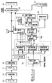
図1には、本発明に係る超音波診断装置の好適な実施形態が示されており、図1はその全体構成を示すブロック図である。
【0040】
送受信部12は、プローブ10を介して対象組織を含む空間内に超音波を送受波することで各時相ごとの三次元超音波画像を、三次元データメモリ14へ出力する。各時相ごとに得られた三次元超音波画像は、座標変換部16において表示座標系に変換された後、各時相ごとに表示画像形成部20およびエッジ抽出部24に出力される。
【0041】
表示画像形成部20は、座標変換部16から出力される座標変換された三次元超音波画像に基づいて、この三次元超音波画像を二次元表面上に投影した投影画像を形成する。投影画像の形成は、例えばボリュームレンダリング法を用いて行われる。また、表示画像形成部20は、三次元超音波画像内における対象組織に関する切断面画像を形成する。切断面画像としては、対象組織の上面からみた切断面(上面図)、正面からみた切断面(正面図)および側面からみた切断面(側面図)の三つの切断面画像が形成される。各切断面の位置はユーザからの切断面位置情報に基づいて設定される。表示画像形成部20で形成された投影画像と三つの切断面画像はディスプレイ22に表示される(ディスプレイ22に表示される画像は、例えば、図2から図5に示すものである)。
【0042】
エッジ抽出部24は、座標変換部16から出力される座標変換された三次元超音波画像に基づいて、各時相ごとに対象組織の表面画像を抽出する。三次元超音波画像は複数のボクセルデータが規則的に配列されたものである。エッジ抽出部24は、三次元超音波画像に対して二値化処理を施すことで、複数のボクセルを、対象組織に対応するボクセル(対象組織ボクセル)と対象組織以外の部位に対応するボクセル(非対象組織ボクセル)とに分別する。そして、三次元超音波画像を構成する全てのボクセルの中で、隣接するボクセルとして少なくとも一つの非対象組織を有する対象組織ボクセルの集合を抽出し、抽出したボクセル集合による対象組織表面画像を抽出する。
【0043】
関心領域発生ブロック30は、エッジ抽出部24から出力される対象組織表面画像、並びに、ユーザから入力される切断面位置情報および楕円体パラメータに基づいて、三次元超音波画像内に楕円体形状の関心領域を形成する。ここで、関心領域発生ブロック30内各部の動作について図2から図5を利用して説明する。なお、以下の説明において図1の記載部分については図1における符号を付すものとする。
【0044】
図2から図5は、楕円体形状の三次元関心領域の形成手法を説明するための図であり、図2は楕円体形状の三次元関心領域70を含む三次元超音波画像の斜視図であり、三次元関心領域70の内部には図示しない対象組織画像が存在する。図3は三次元関心領域70を含む三次元超音波画像の上面図、図4は三次元関心領域70を含む三次元超音波画像の正面図、図5は三次元関心領域70を含む三次元超音波画像の側面図をそれぞれ示している。ここで上面図とは対象組織の上面からみた切断面を、正面図とは対象組織の正面からみた切断面を、側面図とは対象組織の側面からみた切断面を、それぞれ示している。
【0045】
楕円体軸設定部32は、ユーザから入力される切断面位置情報および楕円体パラメータに基づいて楕円体の長軸と短軸を設定する。長軸と短軸の設定にあたり、ユーザは、図3から図5に示す各切断面の位置を決定する。例えば、図3の上面図の位置は、ユーザが切断面(図2に示すyz平面)をx軸方向の所望の位置に移動することで設定される。同様に図4の正面図および図5の側面図についても、ユーザが各面をその面に垂直な座標軸方向に移動させることで所望の位置に設定される。ユーザが設定する切断面位置情報は、表示画像形成部20にも入力されており、表示画像形成部20は切断面位置情報に基づいて座標変換部16から出力される三次元超音波画像の各切断面における切断面画像を形成する。このように、図3から図5に示す上面図、正面図および側面図に対応する各画像は表示画像形成部20において画像形成されてディスプレイ22に表示されるため、ユーザはディスプレイ22に表示される切断面画像を見ながら、各切断面位置を設定することができる。
【0046】
各切断面画像は、三次元超音波画像内に対象組織を取り囲む楕円体形状の関心領域を形成するために利用される。このため、各切断面は切断面内の対象組織画像がなるべく大きくなるように、望ましくは最大になるように、その切断位置が設定される。つまり、ユーザはディスプレイ22に表示される各切断面における対象組織の切断画像を見ながら、各切断面における対象組織の切断画像がなるべく大きくなるような切断面位置を設定する。
【0047】
以上のようにして各切断面が設定された後、楕円体軸設定部32はユーザから入力される楕円体パラメータ情報(X0,Y0,Z0,θ, φ)に基づいて、楕円体の長軸と短軸を設定する。楕円体の中心点位置(X0,Y0,Z0)は、各切断面において対象組織断面図のなるべく中心部分に位置するように設定されるものであり、ユーザが三つの切断面を見ながら設定する。例えば、上面図に基づいて対象組織の中心点になるようにY0,Z0を設定した後、正面図と側面図を参照しながらX0を設定する。もちろん正面図に基づいてX0,Y0を設定した後に上面図および側面図を参照してZ0を設定してもよく、あるいは側面図に基づいてZ0, X0を設定した後に上面図および正面図を参照してY0を設定してもよい。このようにして、楕円体の中心点位置、すなわち、座標(X0,Y0,Z0)に対応した三次元空間内における一つの点が設定される。
【0048】
次に、ユーザは設定した楕円体の中心点位置に基づいて、楕円体長軸の傾きであるθ, φを設定する。傾きθは正面図におけるx軸に対する長軸の傾きである。ユーザは正面図の画像を見ながら正面図内において、楕円体の中心点を通り対象組織内でなるべく長い直線、望ましくは最長の直線を求めてその傾きθを設定する。同様にしてユーザは側面図の画像を見ながら側面図内において、楕円体の中心点を通り対象組織内でなるべく長い直線、望ましくは最長の直線を求めてその傾きφを設定する。このようにして、楕円体の長軸、すなわち、座標(X0,Y0,Z0)および傾きθ,φに対応した三次元空間内における一本の直線が設定される。
【0049】
そして、楕円体軸設定部32は、設定された楕円体の中心点位置および長軸に基づいて楕円体の短軸を設定する。短軸は、三次元空間内において、楕円体中心点を通り長軸に直交する平面内において二本設定される。つまり、正面図内において長軸に直交する直線(正面図短軸)と、側面図内において長軸に直交する直線(側面図短軸)の二本が設定される。
【0050】
以上のようにして、楕円体軸設定部32において、三次元関心領域である楕円体の長軸、正面図短軸および側面図短軸が設定される。
【0051】
図1に戻り、長軸端点検出部34は、楕円体軸設定部32において設定された長軸、および、エッジ抽出部24から出力される各時相ごとの対象組織表面画像に基づいて長軸の端点を検出する。つまり、対象組織表面画像と長軸との複数の交点座標を各時相ごとに算出する。例えば、対象組織が楕円体に近い形状の場合、対象組織表面画像と長軸との交点は二点となる。各時相ごとに算出された複数の交点座標は長軸・短軸設定部40に出力される。
【0052】
正面図短軸端点検出部36は、楕円体軸設定部32において設定された正面図短軸、および、エッジ抽出部24から出力される各時相ごとの対象組織表面画像に基づいて正面図短軸の端点を検出する。つまり、対象組織表面画像と正面図短軸との複数の交点座標を各時相ごとに算出する。例えば、対象組織が楕円体に近い形状の場合、対象組織表面画像と正面図短軸との交点は二点となる。各時相ごとに算出された複数の交点座標は長軸・短軸設定部40に出力される。
【0053】
側面図短軸端点検出部38は、楕円体軸設定部32において設定された側面図短軸、および、エッジ抽出部24から出力される各時相ごとの対象組織表面画像に基づいて側面図短軸の端点を検出する。つまり、対象組織表面画像と側面図短軸との複数の交点座標を各時相ごとに算出する。例えば、対象組織が楕円体に近い形状の場合、対象組織表面画像と側面図短軸との交点は二点となる。各時相ごとに算出された複数の交点座標は長軸・短軸設定部40に出力される。
【0054】
長軸・短軸設定部40は、長軸端点検出部34、正面図短軸端点検出部36および側面図短軸端点検出部38から出力される交点座標に基づいて長軸長および短軸長を設定する。つまり、長軸端点検出部34から各時相ごと出力される複数の交点の中から、楕円体中心点からの距離が最も大きい交点(長軸交点)を各時相ごとに選定する。そして、各時相ごとに選定した長軸交点の中で、楕円体中心点からの距離が最も大きい交点を選定し、選定した長軸交点と楕円体中心点との距離を長軸長とする。
【0055】
また、長軸・短軸設定部40は、正面図短軸端点検出部36から各時相ごと出力される複数の交点の中から、楕円体中心点からの距離が最も大きい交点(正面図短軸交点)を各時相ごとに選定する。そして、各時相ごとに選定した正面図短軸交点の中で、楕円体中心点からの距離が最も大きい交点を選定し、選定した正面図短軸交点と楕円体中心点との距離を正面図短軸長とする。
【0056】
さらに、長軸・短軸設定部40は、側面図短軸端点検出部38から各時相ごと出力される複数の交点の中から、楕円体中心点からの距離が最も大きい交点(側面図短軸交点)を各時相ごとに選定する。そして、各時相ごとに選定した側面図短軸交点の中で、楕円体中心点からの距離が最も大きい交点を選定し、選定した側面図短軸交点と楕円体中心点との距離を側面図短軸長とする。
【0057】
長軸・短軸設定部40は、複数の時相の中から最大の軸長を選定するが、例えば、対象組織が心臓心室の場合、心臓心室は心拍運動により収縮拡張を繰り返しているため、拡張末期時点において長軸・短軸を設定することが望ましい。拡張末期時点は心電波形のR波によって確認されるため、R波発生時点の時相において長軸長、正面図短軸長および側面図短軸長が選定される。
【0058】
関心領域発生部42は、長軸・短軸設定部40から出力される長軸長、正面図短軸長および側面図短軸長に基づいて楕円体形状の関心領域を発生する。関心領域発生部42で発生する楕円体の一般式は次式で表現される。
【数1】

【0059】
点P(x,y,z)がZ軸回りにθ回転する場合の変換は次の行列で表現できる。
【数2】
【数3】
【数4】
【0060】
以上のようにして、関心領域発生ブロック30から出力される楕円体形状の三次元関心領域は、関心領域エッジ抽出部50に出力され、ここで関心領域の表面画像が抽出される。関心領域の表面は、数1における不等号を等号に置き換えた式に、数4の変換式を適用することで得られる。
【0061】
関心領域適合判定部52は、関心領域エッジ抽出部50から出力される関心領域の表面画像、および、座標変換部16から出力される三次元超音波画像が二値化処理部54により二値化処理された二値化画像に基づいて、関心領域内に対象組織が収まっているか否かを判定する。二値化処理部54から出力される二値化画像は、対象組織に対応するボクセル(対象組織ボクセル)と対象組織以外の部位に対応するボクセル(非対象組織ボクセル)とに分別された画像である。そこで、関心領域適合判定部52は、関心領域の表面画像と二値化画像との比較を行い、関心領域の表面画像上に対象組織ボクセルが存在する場合、対象組織画像が関心領域をはみ出したものと判定する。関心領域適合判定部52は、関心領域の表面画像上における対象組織ボクセル部分、つまり、はみ出し表面領域に例えば色付け処理を施して対象組織が関心領域をはみ出していることを明示した画像を形成し、表示画像形成部20に出力する。また、関心領域適合判定部52は、はみ出し表面領域の画像を関心領域修正手段60へも出力する。
【0062】
関心領域修正手段60は、対象組織が関心領域をはみ出した場合に、関心領域を修正する手段である。次に、図6を利用して関心領域修正手段60について説明する。
【0063】
図6は、関心領域修正手段60の内部構成を示すブロック図である。関心領域修正手段60は、重心検出部72、長軸成分検出部74、正面図短軸成分検出部76、側面図短軸成分検出部78および長軸短軸拡大率設定部80で構成される。重心検出部72には、関心領域適合判定部52から出力される、はみ出し表面領域の画像が入力される。はみ出し表面領域の画像は各時相ごとに形成されており、重心検出部72は各時相ごとのはみ出し表面領域を所定時間内で積算する。つまり、所定時間内において一時相でもはみ出しを経験した表面部分を全て抽出する。そして、積算した表面領域の重心点を算出する。なお、積算を行う所定時間としては、例えば対象組織が心臓左室の場合、一心拍が好適である。
【0064】
長軸成分検出部74は、重心検出部72が出力する重心点の位置に基づいて、長軸成分を算出する。長軸成分の算出手法を図7を利用して説明する。長軸成分検出部74は、重心検出部72が出力するはみ出し表面領域の重心点から関心領域の長軸へ垂線を引いてこの垂線と長軸との交点を抽出し、抽出した交点と重心点側に位置する長軸端点との距離g1を算出し、長軸短軸拡大率設定部80へ出力する。
【0065】
図6に戻り、正面図短軸成分検出部76は、重心検出部72が出力する重心点の位置に基づいて、この重心点から関心領域の正面図短軸へ垂線を引いてこの垂線と正面図短軸との交点を抽出し、抽出した交点と重心点側に位置する正面図短軸端点との距離g2を算出し、長軸短軸拡大率設定部80へ出力する。また、側面図短軸成分検出部78は、重心検出部72が出力する重心点の位置に基づいて、この重心点から関心領域の側面図短軸へ垂線を引いてこの垂線と側面図短軸との交点を抽出し、抽出した交点と重心点側に位置する側面図短軸端点との距離g3を算出し、長軸短軸拡大率設定部80へ出力する。
【0066】
長軸短軸拡大率設定部80は、長軸成分検出部74、正面図短軸成分検出部76および側面図短軸成分検出部78からそれぞれ出力されるg1,g2,g3に基づいて、長軸および二つの短軸の拡大率を決定する。拡大率はg1,g2,g3のそれぞれの大きさに応じて予め設定されているものとする。例えば、g1が長軸半径aの1/4以下の場合には、はみ出し表面領域が長軸端点近くに存在すると判断して、長軸半径を2割大きくする。g1が長軸半径aの1/4より大きく1/2以下の場合には、はみ出し表面領域が長軸端点にそれほど近くないものと判断して、長軸半径を1割大きくする。同様に、g2,g3の大きさに基づいて、正面図短軸半径、側面図短軸半径の拡大率が決定される。長軸短軸拡大率設定部80で設定した各軸の拡大率は長軸・短軸設定部(図1の符号40)に出力され、各軸が拡大される。
【0067】
図1に示した長軸・短軸設定部40は、拡大した長軸長、正面図短軸長および側面図短軸長を関心領域発生部42に出力し、関心領域発生部42は拡大した関心領域を生成して関心領域適合判定部52に出力する。このようにして、長軸・短軸を繰り返し拡大修正することで、対象組織がはみ出さない三次元関心領域が形成される。なお、関心領域修正手段60にはユーザからの指示に基づいて、自動修正を停止させる機能があると好適である。これにより、対象組織のある部位が関心領域をはみ出しても、その部位が診断に差し支えないとユーザが判断して関心領域を固定することができる。
【0068】
関心領域発生部42で生成された三次元関心領域は、体積計測部62にも出力される。体積計測部62は、三次元関心領域内において対象組織の各時相における体積を計測するものであり、二値化処理部54から出力される二値化画像に基づいて、三次元関心領域内における対象組織ボクセル数をカウントして対象組織の体積を計測する。各時相ごとに得られた対象組織の体積の計測結果はグラフ形成部64に出力され、各時相ごとの対象組織の体積、つまり計測時刻と体積値を示したグラフが生成され表示画像形成部20を介してディスプレイ22に出力される。なお、グラフ形成部64は、各時相ごとの体積計測結果に基づいて、例えば、体積変化率を演算してグラフ化してもよい。
【0069】
前述したように、関心領域適合判定部52は、はみ出し表面領域に色付け処理を施して、対象組織が関心領域をはみ出していることを明示した画像を形成し、表示画像形成部20に出力する。そして、表示画像形成部20は、座標変換部16から出力される三次元超音波画像と、はみ出し表面領域に色付け処理を施した関心領域表面を合成して、ディスプレイ22に表示する。
【0070】
図8は、図1の超音波診断装置のディスプレイ22に表示される対象組織画像を示す図である。対象組織画像82は、三次元関心領域84をはみ出した部分86に色付け処理が施されて表示されている。ユーザはこの画像を見ることで、対象組織のどの部分が関心領域からはみ出しているのかを知ることができる。
【0071】
図1に示した実施形態において、座標変換部16の直後に並進回転移動キャンセル処理部が挿入されるとさらに好適である。
【0072】
図9は、並進回転移動キャンセル処理部87の内部構成を示すブロック図である。並進回転移動キャンセル処理部87には座標変換部16から出力される三次元超音波画像が入力され、二値化処理部88において、対象組織に対応するボクセル(対象組織ボクセル)と対象組織以外の部位に対応するボクセル(非対象組織ボクセル)とに分別された二値化画像が形成される。
【0073】
心室用ROI(関心領域)発生器90は、対象組織である心臓心室の外縁を成すROIの座標を発生する。心室用ROIは、例えば楕円形状であり、ユーザは超音波画像を見ながら楕円の長軸や短軸の長さ、中心点の位置、楕円の傾きなどの初期値を、ROIの中に心室の画像が収まるように設定する。この際、ユーザは超音波画像を見ながら一心拍分の運動を観察した上で、全ての時相においてROIが心臓左室を含むように、トラックボールなどを操作して初期値を決定する。ROIの設定はユーザによるマニュアル設定に限られるものではなく、心室の動きに応じて装置設定されるものでもよい。
【0074】
心室用ゲート回路92は、心室用ROI内のボクセルデータのみを通過させる回路である。つまり、心室用ゲート回路92の一方の入力端子には心室用ROI発生器90から出力されるROIの座標が入力され、他方の入力端子に入力される二値化画像において心室用ROI内に属する座標のボクセルデータのみを抽出し、心腔抽出部94に出力する。心腔抽出部94は、ROI内の二値化画像から心室内部の心腔画像を抽出する。心室重心演算部96は、心腔抽出部94から出力される心室内部画像における重心点の座標を各時相毎に算出する。算出された心室重心点の座標は読み出しアドレス発生器112および心室重心点メモリ98に出力される。
【0075】
弁輪部用ROI(関心領域)発生器100は、心室端に位置する弁輪部の外縁を成すROIの座標を発生する。弁輪部用ROIは、例えば楕円形状であり、ユーザは超音波画像を見ながら楕円の長軸や短軸の長さ、中心点の位置、楕円の傾きなどの初期値を、ROIの中に弁輪部の画像が収まるように設定する。この際、ユーザは超音波画像を見ながら一心拍分の運動を観察した上で、全ての時相においてROIが弁輪部を含むように、トラックボールなどを操作して初期値を決定する。ROIの設定はユーザによるマニュアル設定に限られるものではなく、弁輪部の動きに応じて装置設定されるものでもよい。
【0076】
弁輪部ゲート回路102は、弁輪部用ROI内のボクセルデータのみを通過させる回路である。つまり、弁輪部用ゲート回路102の一方の入力端子には弁輪部用ROI発生器100から出力されるROIの座標が入力され、他方の入力端子に入力される二値化画像において弁輪部用ROI内に属する座標のボクセルデータのみを抽出し、弁輪部抽出部104に出力する。弁輪部抽出部104は、ROI内の二値化画像から弁輪部画像を抽出する。弁輪部重心演算部106は、弁輪部抽出部104から出力される弁輪部画像に対して弁輪部の重心点の座標を各時相毎に算出する。算出された弁輪部重心点の座標は読み出しアドレス発生器112よび弁輪部重心点メモリ108に出力される。
【0077】
心室重心点メモリ98には心室の拡張末期時の心室重心点の座標が記憶される。拡張末期を知らせるトリガとしては心電波形のR波を利用する。つまり、拡張末期時に得られるR波をトリガとして、心室重心演算部96から出力される心室重心点の座標を拡張末期時の心室重心点の座標として記憶しておく。同様にR波をトリガとして拡張末期時の弁輪部重心点の座標が、弁輪部重心演算部106から弁輪部重心点メモリ108に記憶される。
【0078】
読み出し制御部110は、読み出しアドレス発生器112及びメモリ制御部114で構成されており、各時相のボリューム間における心室の並進移動量及び回転移動量をキャンセルした超音波画像を形成すべく、ボリュームメモリ116からボクセルデータを読み出す。つまり、読み出しアドレス発生器112は、心室重心点メモリ98から拡張末期時の心室重心点の座標を取得し、また、弁輪部重心点メモリ108から拡張末期時の弁輪部重心点の座標を取得する。さらに、心室重心演算部96から現ボリュームにおける心室重心点の座標を取得し、また、弁輪部重心演算部106から現ボリュームにおける弁輪部重心点の座標を取得する。
【0079】
読み出しアドレス発生器112は、現ボリュームの心室重心点が拡張末期時の心室重心点に重なるように、かつ、現ボリュームにおける心室重心点と弁輪部重心点を通る直線が、拡張末期時における心室重心点と弁輪部重心点を通る直線に重なるような読み出しアドレスを演算する。
【0080】
ボリュームメモリ116には二値化処理部88から出力されたボクセルデータが原画像のアドレスのままボリューム毎にコピーされており、メモリ制御部114は、読み出しアドレス発生器112が算出した読み出しアドレスに従ってボリュームメモリ116からボクセルデータを読み出して、表示画像形成部(図1の符号20)およびエッジ抽出部(図1の符号24)に出力する。この結果、ボリュームメモリ116から出力されるボクセルデータに基づいた超音波画像は、対象組織である心臓左室の身体全体に対する相対的な並進移動および回転移動がキャンセルされた超音波画像となる。
【0081】
【発明の効果】
以上説明したように、本発明に係る超音波診断装置により三次元空間内に関心領域を容易に設定することができる。
【図面の簡単な説明】
【図1】本発明に係る超音波診断装置の好適な実施形態を示すブロック図である。
【図2】楕円体形状の三次元関心領域を含む三次元超音波画像の斜視図である。
【図3】三次元関心領域を含む三次元超音波画像の上面図である。
【図4】三次元関心領域を含む三次元超音波画像の正面図である。
【図5】三次元関心領域を含む三次元超音波画像の側面図である。
【図6】関心領域修正手段の内部構成を示すブロック図である。
【図7】長軸成分の算出手法を説明するための図である。
【図8】ディスプレイに表示される対象組織画像を示す図である。
【図9】並進回転移動キャンセル処理部の内部構成を示すブロック図である。
【符号の説明】
24 エッジ抽出部、32 楕円体軸設定部、34 長軸端点検出部、36 正面図短軸端点検出部、38 側面図短軸端点検出部、40 長軸・短軸設定部、42 関心領域発生部、50 関心領域エッジ抽出部、52 関心領域適合判定部、60 関心領域修正手段。[0001]
TECHNICAL FIELD OF THE INVENTION
The present invention relates to an ultrasonic diagnostic apparatus, and more particularly to a three-dimensional ultrasonic diagnostic apparatus capable of setting a region of interest.
[0002]
[Prior art]
In the two-dimensional ultrasonic diagnostic apparatus, the function of diagnosing a site of interest has been improved by setting a region of interest. In other words, the Doppler calculation for forming a color Doppler image in the region of interest reduces the calculation processing time, and the calculation accuracy is reduced by calculating only the region of interest when calculating the area of the target tissue. Was raised. The region of interest is also used in a three-dimensional ultrasonic diagnostic apparatus, and shortens the calculation processing time and improves the accuracy of the area or volume calculation (for example, see Patent Document 1).
[0003]
[Patent Document 1]
JP 2001-37756 A
[0004]
[Problems to be solved by the invention]
However, setting a region of interest in a three-dimensional ultrasonic diagnostic apparatus requires setting the three-dimensional shape of the region of interest and setting the position of the region of interest in three-dimensional space, and the setting operation is complicated for the operator. It is troublesome.
[0005]
Therefore, an object of the present invention is to enable a region of interest to be easily set in a three-dimensional space.
[0006]
[Means for Solving the Problems]
(1) In order to achieve the above object, an ultrasonic diagnostic apparatus according to the present invention transmits and receives an ultrasonic wave to and from a three-dimensional space including a target tissue to form volume data including a plurality of voxel data. Data forming means, based on a plurality of planes having an intersecting relationship set in the three-dimensional space, a reference line setting means for setting a first reference line penetrating the target tissue, the first reference line, And a boundary searching means for searching for a boundary of the target tissue by referring to voxel data along a second reference line intersecting the boundary, and a three-dimensional interest related to the target tissue based on the searched boundary. A shape parameter calculating means for calculating a plurality of shape parameters for specifying a region; and a function for setting the region of interest in the three-dimensional space based on the plurality of shape parameters. It shall have an area setting means.
[0007]
In the above configuration, the boundary of the target tissue defines a site that requires diagnosis, and corresponds to, for example, the surface of the target tissue.
[0008]
According to the above configuration, since the ultrasonic diagnostic apparatus calculates the shape parameter and sets the region of interest based on the shape parameter, the operation of setting the region of interest by the user is simplified, and the region of interest in the three-dimensional space is simplified. Setting becomes easy.
[0009]
Preferably, the apparatus further comprises a reference point setting means for setting a reference point determined based on the structure of the target tissue, wherein the reference line setting means sets an inclination of the first reference line passing through the reference point. Shall be.
[0010]
Preferably, the apparatus further includes a plane image forming unit that forms a plane image including the target tissue on each of the planes based on the volume data, wherein the reference point setting unit is configured to display the plane image on a display. The reference point is set based on the reference point setting information input by the user by using.
[0011]
According to the above configuration, since the user can set the reference point information while visually confirming the position of the reference point with respect to the target tissue, the setting of the reference point is facilitated, and the setting of the region of interest is further facilitated. It will be easier.
[0012]
Preferably, the reference line setting means is reference line inclination information input by a user using each of the plane images displayed on a display, and includes a projection line of the first reference line onto each of the plane images. The inclination of the first reference line is set based on the reference line inclination information indicating the inclination.
[0013]
According to the above configuration, the user can visually confirm the first reference line using the plane image and set the inclination of the first reference line. Area setting becomes easy.
[0014]
Preferably, the reference point setting means sets, as the reference point, a center of gravity of the target tissue calculated based on the volume data.
[0015]
Preferably, the reference line setting means sets an inclination of the first reference line based on boundary information of the target tissue obtained using the volume data.
[0016]
In the above configuration, the inclination of the first reference line may be set, for example, such that the first reference line passes through the inside of the boundary of the target tissue for the longest time, or is set so as to pass through a specific portion of the target tissue boundary. You may.
[0017]
According to the above configuration, it is possible to set the first reference line based on the structure of the target tissue. That is, it is possible to set a region of interest that reflects the structure of the target organization.
[0018]
Preferably, the plurality of planes are orthogonal to each other.
[0019]
According to the above configuration, since the plurality of planes are orthogonal to each other, it is easy to grasp the positional relationship between the planes.
[0020]
Preferably, the second reference line is orthogonal to the first reference line.
[0021]
Preferably, a plurality of the second reference lines are set orthogonal to the first reference line and pass through the reference point.
[0022]
(2) In order to achieve the above object, an ultrasonic diagnostic apparatus according to the present invention transmits and receives ultrasonic waves to and from a three-dimensional space including a target tissue to form volume data including a plurality of voxel data. Volume data forming means, a plane setting means for setting three planes orthogonal to each other in the three-dimensional space, and a first reference line setting means for setting a first reference line passing through the target tissue. A first reference line setting unit that sets the first reference line based on a projection line of the first reference line projected on each of two planes of the three planes; Is projected in one plane, a second reference line setting means for setting a second reference line orthogonal to the first reference line, and in the other plane on which the first reference line is projected, Third reference line setting means for setting a third reference line orthogonal to one reference line, based on the voxel data, a first reference line end point which is an intersection of the boundary of the first reference line and the target tissue. Calculate, calculate a second reference line endpoint that is an intersection of the second reference line and the boundary of the target tissue, and calculate a third reference line endpoint that is an intersection of the third reference line and the boundary of the target tissue. A reference line end point calculating means for calculating, and setting a first axis determined to have a predetermined length on the first reference line based on the first reference line end point, and setting the first axis based on the second reference line end point. Axis setting for setting a second axis determined to have a predetermined length on two reference lines, and for setting a third axis determined to have a predetermined length on the third reference line based on the end points of the third reference line Means, based on the set first axis, second axis and third axis, Serial shall have a region of interest setting means for setting a region of interest ellipsoidal shape in three-dimensional space.
[0023]
In the above configuration, the three planes can be set at arbitrary positions, for example, the upper surface, the front surface, and the side surface of the target tissue. Further, the first reference line end point, the second reference line end point, and the third reference line end point may each be plural depending on the shape of the boundary of the target tissue. The target tissue includes, for example, a heart chamber in the left ventricle of the heart. In this case, the left indoor wall corresponds to the boundary of the target tissue.
[0024]
According to the above configuration, since the ellipsoidal shape and the position thereof are determined based on the first axis, the second axis, and the third axis, the ellipsoidal region of interest can be easily set in the three-dimensional space.
[0025]
Preferably, a plane image forming means for forming a plane image including the target tissue on each of the planes based on the volume data, and a reference point setting for setting a reference point determined based on the structure of the target tissue Means for setting the reference point based on reference point setting information input by a user using the respective plane images displayed on a display, further comprising: The line setting means sets the first reference line passing through the reference point based on a tilt angle of the projection line input by a user using the plane images displayed on a display, and sets the second reference line. And the third reference line passes through the reference point.
[0026]
With the above configuration, the user can set the reference point and the first reference line at desired positions, and the ultrasonic diagnostic apparatus sets an ellipsoidal region of interest based on these setting information. The region of interest can be easily set at a desired position.
[0027]
Preferably, the plane setting unit determines the positions of the three planes based on position information of each plane input by a user, and the plane image forming unit determines the target on each of the planes as the plane image. It is assumed that a cut surface image of the tissue is formed.
[0028]
According to the above configuration, the user can set three cut planes at desired positions, and can set the first reference line using the cut planes.
[0029]
Desirably, the axis setting means sets the length of each of the first axis, the second axis, and the third axis to the length of each axis protruding outside beyond the boundary of the target tissue, The region of interest setting means sets an ellipsoidal region of interest surrounding the inside of the boundary of the target tissue.
[0030]
According to the above configuration, the ellipsoidal shape serving as the region of interest is set to be larger than the inside of the boundary of the target tissue to be diagnosed. For this reason, it is possible to set a region of interest surrounding substantially all of the part to be diagnosed, preferably all of the part to be diagnosed.
[0031]
Preferably, the apparatus further includes a region of interest determination unit that determines, based on the volume data and the region of interest, that the inside of the boundary of the target tissue is outside the region of interest.
[0032]
Preferably, when the voxel inside the boundary of the target tissue is included on the surface of the region of interest, the region-of-interest determination means determines that the inside of the boundary of the target tissue is outside the region of interest.
[0033]
Preferably, the apparatus further includes a region-of-interest correcting means for resetting the first axis, the second axis, and the third axis when the inside of the boundary of the target tissue is outside the region of interest.
[0034]
According to the above configuration, since the region of interest is corrected, the accuracy of setting the region of interest is improved, and the accuracy of diagnosis by the ultrasonic diagnostic apparatus is further increased.
[0035]
Preferably, the region-of-interest correcting means resets the lengths of the first axis, the second axis, and the third axis based on a position of a protruding portion inside a boundary of the target tissue on a surface of the region of interest. It shall be.
[0036]
Desirably, the image processing apparatus further includes a protruding image forming unit that forms a protruding image by performing a predetermined display process on a protruding portion inside the boundary of the target tissue on the surface of the region of interest.
[0037]
According to the above configuration, the user can easily confirm the protruding portion of the part to be diagnosed by seeing the protruding image displayed on the display. Therefore, the influence of the protruding portion on the diagnosis can be estimated. For example, when it is determined that the influence on the diagnosis is small, the diagnosis can be continued without resetting the region of interest.
[0038]
BEST MODE FOR CARRYING OUT THE INVENTION
Hereinafter, preferred embodiments of the present invention will be described with reference to the drawings.
[0039]
FIG. 1 shows a preferred embodiment of an ultrasonic diagnostic apparatus according to the present invention, and FIG. 1 is a block diagram showing the entire configuration.
[0040]
The transmitting / receiving
[0041]
The display
[0042]
The
[0043]
The region-of-
[0044]
2 to 5 are diagrams for explaining a method of forming an ellipsoidal three-dimensional region of interest, and FIG. 2 is a perspective view of a three-dimensional ultrasonic image including an ellipsoidal three-dimensional region of
[0045]
The ellipsoid
[0046]
Each cross-section image is used to form an ellipsoidal region of interest surrounding the target tissue in the three-dimensional ultrasound image. For this reason, the cutting position of each cut plane is set so that the target tissue image in the cut plane is as large as possible, and preferably maximum. That is, the user sets the cut plane position such that the cut image of the target tissue on each cut plane is as large as possible while viewing the cut images of the target tissue on each cut plane displayed on the
[0047]
After each cutting plane is set as described above, the ellipsoid
[0048]
Next, the user sets θ, φ, which are the inclinations of the ellipsoid long axis, based on the set center point position of the ellipsoid. Is the inclination of the long axis with respect to the x-axis in the front view. While observing the image of the front view, the user obtains a straight line as long as possible within the target tissue, desirably the longest straight line passing through the center point of the ellipsoid in the front view, and sets the inclination θ thereof. Similarly, the user obtains a straight line as long as possible within the target tissue, preferably the longest straight line passing through the center point of the ellipsoid in the side view while viewing the image of the side view, and sets the inclination φ thereof. In this way, the major axis of the ellipsoid, that is, the coordinates (X 0 , Y 0 , Z 0 ) And one straight line in a three-dimensional space corresponding to the inclinations θ and φ.
[0049]
Then, the ellipsoid
[0050]
As described above, in the ellipsoid
[0051]
Returning to FIG. 1, the major axis end
[0052]
The front view short axis end point detection unit 36 detects the front view short axis based on the front view short axis set by the ellipsoid
[0053]
The side view short-axis end
[0054]
The major axis / minor axis setting unit 40 is configured to determine a major axis length and a minor axis length based on intersection coordinates output from the major axis end
[0055]
In addition, the long axis / short axis setting unit 40 selects, from among the plurality of intersections output from the front view short axis end point detection unit 36 for each time phase, the intersection (the short distance in the front view) Axis intersection point) is selected for each time phase. Then, among the front view short axis intersections selected for each time phase, an intersection having the largest distance from the ellipsoid center is selected, and the distance between the selected front view short axis intersection and the ellipsoid center is determined by the front. The figure shall be the short axis length.
[0056]
Further, the long axis / short axis setting section 40 selects, from among the plurality of intersections output for each time phase from the side view short axis end
[0057]
The long axis / short axis setting unit 40 selects the maximum axis length from a plurality of time phases. For example, when the target tissue is a heart ventricle, the heart ventricle repeatedly contracts and expands due to heartbeat, It is desirable to set the major axis and minor axis at the end of diastole. Since the end-diastolic time is confirmed by the R wave of the electrocardiographic waveform, the long axis length, the front view short axis length, and the side view short axis length are selected in the time phase when the R wave occurs.
[0058]
The region of interest generator 42 generates an ellipsoidal region of interest based on the major axis length, the minor axis length in the front view, and the minor axis length in the side view output from the major axis / minor axis setting unit 40. The general formula of the ellipsoid generated by the region of interest generator 42 is expressed by the following formula.
(Equation 1)
[0059]
The transformation when the point P (x, y, z) rotates θ around the Z axis can be expressed by the following matrix.
(Equation 2)
[Equation 3]
(Equation 4)
[0060]
As described above, the ellipsoidal three-dimensional region of interest output from the region of
[0061]
The region-of-interest determination unit 52 binarizes the surface image of the region of interest output from the region-of-
[0062]
The region-of-
[0063]
FIG. 6 is a block diagram showing the internal configuration of the region of interest correction means 60. The region-of-interest correction means 60 includes a center-of-
[0064]
The long axis component detection unit 74 calculates a long axis component based on the position of the center of gravity output from the center of
[0065]
Returning to FIG. 6, the front view short axis component detection unit 76 draws a perpendicular from the center of gravity point to the front view short axis of the region of interest based on the position of the center of gravity output from the center of
[0066]
The major axis minor axis enlargement
[0067]
The major axis / minor axis setting unit 40 shown in FIG. 1 outputs the enlarged major axis length, the front view minor axis length, and the side view minor axis length to the region of interest generator 42, and the region of interest generator 42 is enlarged. A region of interest is generated and output to the region of interest matching determination unit 52. In this way, by repeatedly enlarging and correcting the long axis and the short axis, a three-dimensional region of interest in which the target tissue does not protrude is formed. It is preferable that the region-of-
[0068]
The three-dimensional region of interest generated by the region of interest generator 42 is also output to the
[0069]
As described above, the region of interest matching determination unit 52 applies a coloring process to the protruding surface region to form an image clearly indicating that the target tissue is protruding from the region of interest, and outputs the image to the display
[0070]
FIG. 8 is a diagram showing a target tissue image displayed on the
[0071]
In the embodiment shown in FIG. 1, it is more preferable that a translation / rotation / movement canceling processing unit is inserted immediately after the coordinate
[0072]
FIG. 9 is a block diagram illustrating an internal configuration of the translational rotation movement canceling processing unit 87. The three-dimensional ultrasonic image output from the coordinate
[0073]
The ventricle ROI (region of interest)
[0074]
The
[0075]
The annulus ROI (region of interest)
[0076]
The
[0077]
The
[0078]
The
[0079]
The
[0080]
The voxel data output from the
[0081]
【The invention's effect】
As described above, the ultrasonic diagnostic apparatus according to the present invention can easily set a region of interest in a three-dimensional space.
[Brief description of the drawings]
FIG. 1 is a block diagram showing a preferred embodiment of an ultrasonic diagnostic apparatus according to the present invention.
FIG. 2 is a perspective view of a three-dimensional ultrasonic image including an ellipsoidal three-dimensional region of interest.
FIG. 3 is a top view of a three-dimensional ultrasound image including a three-dimensional region of interest.
FIG. 4 is a front view of a three-dimensional ultrasonic image including a three-dimensional region of interest.
FIG. 5 is a side view of a three-dimensional ultrasound image including a three-dimensional region of interest.
FIG. 6 is a block diagram showing an internal configuration of a region of interest correction means.
FIG. 7 is a diagram for explaining a calculation method of a long axis component.
FIG. 8 is a diagram showing a target tissue image displayed on a display.
FIG. 9 is a block diagram illustrating an internal configuration of a translation rotation movement canceling processing unit;
[Explanation of symbols]
24 Edge extraction unit, 32 Ellipsoid axis setting unit, 34 Long axis end point detection unit, 36 Front view short axis end point detection unit, 38 Side view short axis end point detection unit, 40 Long axis / short axis setting unit, 42 Region of interest generation Unit, 50 region of interest edge extraction unit, 52 region of interest adaptation determination unit, 60 region of interest correction means.
Claims (18)
前記三次元空間内に設定される互いに交差関係にある複数のプレーンに基づいて、前記対象組織を貫く第一基準線を設定する基準線設定手段と、
前記第一基準線、および、それに交差する第二基準線に沿って、ボクセルデータを参照して、前記対象組織の境界を探索する境界探索手段と、
前記探索された境界に基づいて、前記対象組織に関する三次元の関心領域を特定するための複数の形状パラメータを演算する形状パラメータ演算手段と、
前記複数の形状パラメータに基づいて前記三次元空間内に前記関心領域を設定する関心領域設定手段と、
を有することを特徴とする超音波診断装置。Volume data forming means for transmitting and receiving ultrasonic waves to and from a three-dimensional space including the target tissue to form volume data composed of a plurality of voxel data,
Reference line setting means for setting a first reference line penetrating the target tissue, based on a plurality of planes having an intersecting relationship set in the three-dimensional space,
The first reference line, and, along a second reference line crossing the first reference line, with reference to voxel data, a boundary search means for searching for a boundary of the target tissue,
Based on the searched boundary, a shape parameter calculating means for calculating a plurality of shape parameters for specifying a three-dimensional region of interest for the target tissue,
A region of interest setting means for setting the region of interest in the three-dimensional space based on the plurality of shape parameters,
An ultrasonic diagnostic apparatus comprising:
前記対象組織の構造に基づいて決定される基準点を設定する基準点設定手段をさらに有し、
前記基準線設定手段は、前記基準点を通る前記第一基準線の傾きを設定する、ことを特徴とする超音波診断装置。The ultrasonic diagnostic apparatus according to claim 1,
Further comprising a reference point setting means for setting a reference point determined based on the structure of the target tissue,
The ultrasonic diagnostic apparatus, wherein the reference line setting means sets an inclination of the first reference line passing through the reference point.
前記ボリュームデータに基づいて、前記各プレーン上において前記対象組織を含むプレーン画像を形成するプレーン画像形成手段をさらに有し、
前記基準点設定手段は、ディスプレイに表示される前記各プレーン画像を利用してユーザが入力する基準点設定情報に基づいて前記基準点を設定する、
ことを特徴とする超音波診断装置。The ultrasonic diagnostic apparatus according to claim 2,
A plane image forming unit that forms a plane image including the target tissue on each of the planes based on the volume data;
The reference point setting means sets the reference point based on reference point setting information input by a user using the plane images displayed on a display,
An ultrasonic diagnostic apparatus, comprising:
前記基準線設定手段は、ディスプレイに表示される前記各プレーン画像を利用してユーザが入力する基準線傾き情報であって、前記第一基準線の前記各プレーン画像への投影線の傾きを表す基準線傾き情報に基づいて前記第一基準線の傾きを設定する、
ことを特徴とする超音波診断装置。The ultrasonic diagnostic apparatus according to claim 3,
The reference line setting means is reference line inclination information input by a user using each of the plane images displayed on a display, and represents inclination of a projection line of the first reference line onto each of the plane images. Setting the inclination of the first reference line based on the reference line inclination information,
An ultrasonic diagnostic apparatus, comprising:
前記基準点設定手段は、前記基準点として、前記ボリュームデータに基づいて演算される前記対象組織の重心点を設定する、
ことを特徴とする超音波診断装置。The ultrasonic diagnostic apparatus according to claim 2,
The reference point setting means sets a center of gravity of the target tissue calculated based on the volume data as the reference point,
An ultrasonic diagnostic apparatus, comprising:
前記基準線設定手段は、前記ボリュームデータを利用して得られる前記対象組織の境界情報に基づいて前記第一基準線の傾きを設定する、
ことを特徴とする超音波診断装置。The ultrasonic diagnostic apparatus according to claim 5,
The reference line setting means sets an inclination of the first reference line based on boundary information of the target tissue obtained using the volume data,
An ultrasonic diagnostic apparatus, comprising:
前記複数のプレーンは、互いに直交関係にあることを特徴とする超音波診断装置。The ultrasonic diagnostic apparatus according to any one of claims 1 to 6,
An ultrasonic diagnostic apparatus, wherein the plurality of planes are orthogonal to each other.
前記第二基準線は、前記第一基準線に直交することを特徴とする超音波診断装置。The ultrasonic diagnostic apparatus according to any one of claims 1 to 7,
An ultrasonic diagnostic apparatus, wherein the second reference line is orthogonal to the first reference line.
前記第二基準線は、前記第一基準線に直交し且つ前記基準点を通り複数設定されることを特徴とする超音波診断装置。The ultrasonic diagnostic apparatus according to any one of claims 2 to 7,
An ultrasonic diagnostic apparatus, wherein a plurality of the second reference lines are set orthogonal to the first reference line and pass through the reference point.
前記三次元空間内において互いに直交関係にある三つのプレーンを設定するプレーン設定手段と、
前記対象組織を貫く第一基準線を設定する第一基準線設定手段であって、前記三つのプレーンのうちの二つのプレーンの各々に投影される前記第一基準線の投影線に基づいて、前記第一基準線を設定する第一基準線設定手段と、
前記第一基準線が投影された一方のプレーン内において、前記第一基準線に直交する第二基準線を設定する第二基準線設定手段と、
前記第一基準線が投影された他方のプレーン内において、前記第一基準線に直交する第三基準線を設定する第三基準線設定手段と、
前記ボクセルデータに基づいて、前記第一基準線と前記対象組織の境界との交点である第一基準線端点を演算し、前記第二基準線と前記対象組織の境界との交点である第二基準線端点を演算し、前記第三基準線と前記対象組織の境界との交点である第三基準線端点を演算する基準線端点演算手段と、
前記第一基準線端点に基づいて前記第一基準線上において所定の長さに決定される第一軸を設定し、前記第二基準線端点に基づいて前記第二基準線上において所定の長さに決定される第二軸を設定し、前記第三基準線端点に基づいて前記第三基準線上において所定の長さに決定される第三軸を設定する軸設定手段と、
前記設定された第一軸、第二軸および第三軸に基づいて、前記三次元空間内に楕円体形状の関心領域を設定する関心領域設定手段と、
を有することを特徴とする超音波診断装置。Volume data forming means for transmitting and receiving ultrasonic waves to and from a three-dimensional space including the target tissue to form volume data composed of a plurality of voxel data,
Plane setting means for setting three planes that are orthogonal to each other in the three-dimensional space,
A first reference line setting means for setting a first reference line penetrating the target tissue, based on a projection line of the first reference line projected on each of two planes of the three planes, First reference line setting means for setting the first reference line,
In one plane on which the first reference line is projected, second reference line setting means for setting a second reference line orthogonal to the first reference line,
In the other plane on which the first reference line is projected, third reference line setting means for setting a third reference line orthogonal to the first reference line,
Based on the voxel data, calculate a first reference line end point that is an intersection of the first reference line and the boundary of the target tissue, a second intersection that is the intersection of the second reference line and the boundary of the target tissue. Reference line end point calculating means for calculating a reference line end point and calculating a third reference line end point which is an intersection of the third reference line and the boundary of the target tissue,
Set a first axis determined to a predetermined length on the first reference line based on the first reference line end point, to a predetermined length on the second reference line based on the second reference line end point Axis setting means to set the determined second axis, to set a third axis determined to a predetermined length on the third reference line based on the third reference line end point,
Based on the set first axis, the second axis and the third axis, a region of interest setting means for setting an ellipsoidal region of interest in the three-dimensional space,
An ultrasonic diagnostic apparatus comprising:
前記ボリュームデータに基づいて、前記各プレーン上において前記対象組織を含むプレーン画像を形成するプレーン画像形成手段と、
前記対象組織の構造に基づいて決定される基準点を設定する基準点設定手段であって、ディスプレイに表示される前記各プレーン画像を利用してユーザが入力する基準点設定情報に基づいて前記基準点を設定する基準点設定手段と、をさらに有し、
前記第一基準線設定手段は、ディスプレイに表示される前記各プレーン画像を利用してユーザが入力する前記投影線の傾き角度に基づいて前記基準点を通る前記第一基準線を設定し、
前記第二基準線および前記第三基準線はそれぞれ前記基準点を通る、
ことを特徴とする超音波診断装置。The ultrasonic diagnostic apparatus according to claim 10,
Based on the volume data, a plane image forming means for forming a plane image including the target tissue on each of the planes,
Reference point setting means for setting a reference point determined based on the structure of the target tissue, wherein the reference point is set based on reference point setting information input by a user using the plane images displayed on a display. Reference point setting means for setting a point,
The first reference line setting means sets the first reference line passing through the reference point based on the inclination angle of the projection line input by a user using the plane images displayed on a display,
The second reference line and the third reference line each pass through the reference point,
An ultrasonic diagnostic apparatus, comprising:
前記プレーン設定手段は、ユーザが入力する各プレーンの位置情報に基づいて前記三つのプレーンの位置を決定し、
前記プレーン画像形成手段は、前記プレーン画像として、前記各プレーン上における前記対象組織の切断面画像を形成する、
ことを特徴とする超音波診断装置。An ultrasonic diagnostic apparatus according to claim 11,
The plane setting means determines the positions of the three planes based on position information of each plane input by a user,
The plane image forming unit forms, as the plane image, a cut surface image of the target tissue on each of the planes,
An ultrasonic diagnostic apparatus, comprising:
前記軸設定手段は、前記第一軸、第二軸および第三軸の各軸の長さとして、各軸が前記対象組織の境界を超えて外部に突き出る長さに設定し、
前記関心領域設定手段は、前記対象組織の境界内部を取り囲む楕円体形状の関心領域を設定する、
ことを特徴とする超音波診断装置。An ultrasonic diagnostic apparatus according to claim 12,
The axis setting means, as the length of each axis of the first axis, the second axis and the third axis, each axis is set to the length protruding outside beyond the boundary of the target tissue,
The region of interest setting means sets an ellipsoidal region of interest surrounding the inside of the boundary of the target tissue,
An ultrasonic diagnostic apparatus, comprising:
前記ボリュームデータおよび前記関心領域に基づいて、前記対象組織の境界内部が前記関心領域をはみ出したことを判定する関心領域判定手段をさらに有することを特徴とする超音波診断装置。An ultrasonic diagnostic apparatus according to claim 13,
An ultrasonic diagnostic apparatus further comprising a region-of-interest determining means for determining, based on the volume data and the region of interest, that the inside of the boundary of the target tissue has protruded from the region of interest.
前記関心領域判定手段は、前記関心領域の表面上に前記対象組織の境界内部のボクセルが含まれる場合、前記対象組織の境界内部が前記関心領域をはみ出したと判定することを特徴とする超音波診断装置。An ultrasonic diagnostic apparatus according to claim 14,
Ultrasound diagnosis, wherein the region of interest determining means determines that the inside of the boundary of the target tissue has protruded beyond the region of interest when a voxel inside the boundary of the target tissue is included on the surface of the region of interest. apparatus.
前記対象組織の境界内部が前記関心領域をはみ出した場合、前記第一軸、第二軸および第三軸を再設定する関心領域修正手段をさらに有することを特徴とする超音波診断装置。An ultrasonic diagnostic apparatus according to claim 15,
An ultrasonic diagnostic apparatus further comprising a region-of-interest correcting means for resetting the first axis, the second axis, and the third axis when the inside of the boundary of the target tissue protrudes from the region of interest.
前記関心領域修正手段は、前記関心領域の表面上における前記対象組織の境界内部のはみ出し部分の位置に基づいて、前記第一軸、第二軸および第三軸の長さを再設定することを特徴とする超音波診断装置。An ultrasonic diagnostic apparatus according to claim 16,
The region of interest correcting means may reset the lengths of the first axis, the second axis, and the third axis based on the position of the protruding portion inside the boundary of the target tissue on the surface of the region of interest. Ultrasound diagnostic device characterized by the following.
前記関心領域の表面上における前記対象組織の境界内部のはみ出し部分に所定の表示処理を施したはみ出し画像を形成するはみ出し画像形成手段をさらに有することを特徴とする超音波診断装置。An ultrasonic diagnostic apparatus according to claim 17,
An ultrasonic diagnostic apparatus, further comprising: a protruding image forming unit that forms a protruding image by performing a predetermined display process on a protruding portion inside a boundary of the target tissue on a surface of the region of interest.
Priority Applications (4)
| Application Number | Priority Date | Filing Date | Title |
|---|---|---|---|
| JP2002377976A JP3905470B2 (en) | 2002-12-26 | 2002-12-26 | Ultrasonic diagnostic equipment |
| EP03025737A EP1433422B1 (en) | 2002-12-26 | 2003-11-10 | Ultrasonic diagnostic device |
| US10/714,341 US6878114B2 (en) | 2002-12-26 | 2003-11-14 | Ultrasonic diagnostic device |
| CN200310123429.1A CN1513421B (en) | 2002-12-26 | 2003-12-26 | Ultrasonic diagnostic device |
Applications Claiming Priority (1)
| Application Number | Priority Date | Filing Date | Title |
|---|---|---|---|
| JP2002377976A JP3905470B2 (en) | 2002-12-26 | 2002-12-26 | Ultrasonic diagnostic equipment |
Publications (2)
| Publication Number | Publication Date |
|---|---|
| JP2004202132A true JP2004202132A (en) | 2004-07-22 |
| JP3905470B2 JP3905470B2 (en) | 2007-04-18 |
Family
ID=32463595
Family Applications (1)
| Application Number | Title | Priority Date | Filing Date |
|---|---|---|---|
| JP2002377976A Expired - Fee Related JP3905470B2 (en) | 2002-12-26 | 2002-12-26 | Ultrasonic diagnostic equipment |
Country Status (4)
| Country | Link |
|---|---|
| US (1) | US6878114B2 (en) |
| EP (1) | EP1433422B1 (en) |
| JP (1) | JP3905470B2 (en) |
| CN (1) | CN1513421B (en) |
Cited By (8)
| Publication number | Priority date | Publication date | Assignee | Title |
|---|---|---|---|---|
| JP2007272403A (en) * | 2006-03-30 | 2007-10-18 | Toshiba Corp | Cad device and cad method |
| JP2008006294A (en) * | 2006-06-29 | 2008-01-17 | Medison Co Ltd | Ultrasound system and method for forming ultrasound image |
| JP2008180555A (en) * | 2007-01-23 | 2008-08-07 | Nihon Medi Physics Co Ltd | Apparatus and method for image processing and program |
| JP2008194189A (en) * | 2007-02-13 | 2008-08-28 | Aloka Co Ltd | Ultrasonic diagnostic apparatus |
| JP2009011468A (en) * | 2007-07-03 | 2009-01-22 | Aloka Co Ltd | Ultrasound diagnosis apparatus |
| JP2009106426A (en) * | 2007-10-29 | 2009-05-21 | Aloka Co Ltd | Ultrasonic diagnostic apparatus |
| JP2009183349A (en) * | 2008-02-04 | 2009-08-20 | Aloka Co Ltd | Volume data processor |
| JP2013135974A (en) * | 2013-04-10 | 2013-07-11 | Hitachi Aloka Medical Ltd | Ultrasonic diagnosis apparatus |
Families Citing this family (19)
| Publication number | Priority date | Publication date | Assignee | Title |
|---|---|---|---|---|
| JP4192545B2 (en) * | 2002-09-27 | 2008-12-10 | 株式会社日立メディコ | Ultrasonic diagnostic equipment |
| JP4058368B2 (en) * | 2003-03-27 | 2008-03-05 | ジーイー・メディカル・システムズ・グローバル・テクノロジー・カンパニー・エルエルシー | Ultrasonic diagnostic equipment |
| WO2004093687A1 (en) * | 2003-04-16 | 2004-11-04 | Eastern Virginia Medical School | System and method for generating operator independent ultrasound images |
| JP3802508B2 (en) * | 2003-04-21 | 2006-07-26 | アロカ株式会社 | Ultrasonic diagnostic equipment |
| KR100907967B1 (en) * | 2004-05-14 | 2009-07-16 | 파나소닉 주식회사 | Ultrasound Diagnostic Device and Ultrasound Image Display Method |
| WO2006016285A1 (en) * | 2004-08-05 | 2006-02-16 | Koninklijke Philips Electronics N.V. | Imaging system |
| US8422749B2 (en) * | 2006-06-26 | 2013-04-16 | Koninklijke Philips Electronics N.V. | Method and system for myocardial region of interest definition |
| DE102006049309B4 (en) * | 2006-10-19 | 2008-07-24 | Tomtec Imaging Systems Gmbh | Method, device and computer program product for evaluating medical image data records |
| CN101527047B (en) | 2008-03-05 | 2013-02-13 | 深圳迈瑞生物医疗电子股份有限公司 | Method and device for detecting tissue boundaries by use of ultrasonic images |
| WO2010018513A2 (en) * | 2008-08-12 | 2010-02-18 | Koninklijke Philips Electronics N.V. | Method of meshing and calculating a volume in an ultrasound imaging system |
| KR101120684B1 (en) * | 2009-09-08 | 2012-03-29 | 삼성메디슨 주식회사 | Ultrasound system and method for providing 3-dimensional ultrasound image based on roi of ellipsoid |
| JP5087694B2 (en) * | 2011-04-14 | 2012-12-05 | 日立アロカメディカル株式会社 | Ultrasonic diagnostic equipment |
| US8798342B2 (en) * | 2011-05-10 | 2014-08-05 | General Electric Company | Method and system for ultrasound imaging with cross-plane images |
| WO2012169177A1 (en) * | 2011-06-07 | 2012-12-13 | パナソニック株式会社 | Ultrasonic diagnostic device and ultrasonic diagnostic method |
| CN103417243B (en) * | 2012-05-24 | 2015-05-27 | 中慧医学成像有限公司 | Three-dimensional ultrasonic imaging device, three-dimensional ultrasonic imaging system and three-dimensional ultrasonic imaging method |
| US9690840B2 (en) * | 2013-07-23 | 2017-06-27 | Aware, Inc. | Data analysis engine |
| EP3393366A1 (en) * | 2015-12-21 | 2018-10-31 | Koninklijke Philips N.V. | Ultrasound imaging apparatus and ultrasound imaging method for inspecting a volume of subject |
| US11717268B2 (en) * | 2016-11-29 | 2023-08-08 | Koninklijke Philips N.V. | Ultrasound imaging system and method for compounding 3D images via stitching based on point distances |
| CN108294780A (en) * | 2018-01-31 | 2018-07-20 | 深圳开立生物医疗科技股份有限公司 | ultrasonic three-dimensional imaging method, ultrasonic three-dimensional imaging system and device |
Citations (3)
| Publication number | Priority date | Publication date | Assignee | Title |
|---|---|---|---|---|
| JPH08206117A (en) * | 1994-05-27 | 1996-08-13 | Fujitsu Ltd | Ultrasonic diagnostic apparatus |
| JPH09285465A (en) * | 1996-04-24 | 1997-11-04 | Aloka Co Ltd | Ultrasonic diagnostic device |
| JP2000107183A (en) * | 1998-09-30 | 2000-04-18 | Matsushita Electric Ind Co Ltd | Method and apparatus for metering volume of internal organ |
Family Cites Families (15)
| Publication number | Priority date | Publication date | Assignee | Title |
|---|---|---|---|---|
| US5322067A (en) * | 1993-02-03 | 1994-06-21 | Hewlett-Packard Company | Method and apparatus for determining the volume of a body cavity in real time |
| US5465721A (en) * | 1994-04-22 | 1995-11-14 | Hitachi Medical Corporation | Ultrasonic diagnostic apparatus and ultrasonic diagnosis method |
| US5911691A (en) * | 1996-05-21 | 1999-06-15 | Aloka Co., Ltd. | Ultrasound image processing apparatus and method of forming and displaying ultrasound images by the apparatus |
| US5724978A (en) * | 1996-09-20 | 1998-03-10 | Cardiovascular Imaging Systems, Inc. | Enhanced accuracy of three-dimensional intraluminal ultrasound (ILUS) image reconstruction |
| US5871019A (en) * | 1996-09-23 | 1999-02-16 | Mayo Foundation For Medical Education And Research | Fast cardiac boundary imaging |
| DE69737720T2 (en) * | 1996-11-29 | 2008-01-10 | London Health Sciences Centre, London | IMPROVED IMAGE PROCESSING METHOD FOR A THREE-DIMENSIONAL IMAGE GENERATION SYSTEM |
| US6106466A (en) * | 1997-04-24 | 2000-08-22 | University Of Washington | Automated delineation of heart contours from images using reconstruction-based modeling |
| US6282307B1 (en) * | 1998-02-23 | 2001-08-28 | Arch Development Corporation | Method and system for the automated delineation of lung regions and costophrenic angles in chest radiographs |
| US6245017B1 (en) * | 1998-10-30 | 2001-06-12 | Kabushiki Kaisha Toshiba | 3D ultrasonic diagnostic apparatus |
| US6193660B1 (en) * | 1999-03-31 | 2001-02-27 | Acuson Corporation | Medical diagnostic ultrasound system and method for region of interest determination |
| JP2001037756A (en) | 1999-07-30 | 2001-02-13 | Toshiba Corp | Ultrasonic diagnostic device |
| US6254540B1 (en) * | 1999-11-19 | 2001-07-03 | Olympus Optical Co., Ltd. | Ultrasonic image processing apparatus for constructing three-dimensional image using volume-rendering data and surface-rendering data simultaneously |
| US6443896B1 (en) * | 2000-08-17 | 2002-09-03 | Koninklijke Philips Electronics N.V. | Method for creating multiplanar ultrasonic images of a three dimensional object |
| US6375616B1 (en) * | 2000-11-10 | 2002-04-23 | Biomedicom Ltd. | Automatic fetal weight determination |
| US6491632B1 (en) * | 2001-06-26 | 2002-12-10 | Geoffrey L. Taylor | Method and apparatus for photogrammetric orientation of ultrasound images |
-
2002
- 2002-12-26 JP JP2002377976A patent/JP3905470B2/en not_active Expired - Fee Related
-
2003
- 2003-11-10 EP EP03025737A patent/EP1433422B1/en not_active Expired - Fee Related
- 2003-11-14 US US10/714,341 patent/US6878114B2/en not_active Expired - Fee Related
- 2003-12-26 CN CN200310123429.1A patent/CN1513421B/en not_active Expired - Fee Related
Patent Citations (3)
| Publication number | Priority date | Publication date | Assignee | Title |
|---|---|---|---|---|
| JPH08206117A (en) * | 1994-05-27 | 1996-08-13 | Fujitsu Ltd | Ultrasonic diagnostic apparatus |
| JPH09285465A (en) * | 1996-04-24 | 1997-11-04 | Aloka Co Ltd | Ultrasonic diagnostic device |
| JP2000107183A (en) * | 1998-09-30 | 2000-04-18 | Matsushita Electric Ind Co Ltd | Method and apparatus for metering volume of internal organ |
Cited By (10)
| Publication number | Priority date | Publication date | Assignee | Title |
|---|---|---|---|---|
| JP2007272403A (en) * | 2006-03-30 | 2007-10-18 | Toshiba Corp | Cad device and cad method |
| JP2008006294A (en) * | 2006-06-29 | 2008-01-17 | Medison Co Ltd | Ultrasound system and method for forming ultrasound image |
| US8103066B2 (en) | 2006-06-29 | 2012-01-24 | Medison Co., Ltd. | Ultrasound system and method for forming an ultrasound image |
| JP2008180555A (en) * | 2007-01-23 | 2008-08-07 | Nihon Medi Physics Co Ltd | Apparatus and method for image processing and program |
| JP2008194189A (en) * | 2007-02-13 | 2008-08-28 | Aloka Co Ltd | Ultrasonic diagnostic apparatus |
| JP2009011468A (en) * | 2007-07-03 | 2009-01-22 | Aloka Co Ltd | Ultrasound diagnosis apparatus |
| US8333701B2 (en) | 2007-07-03 | 2012-12-18 | Hitachi Aloka Medical, Ltd. | Ultrasound diagnosis apparatus |
| JP2009106426A (en) * | 2007-10-29 | 2009-05-21 | Aloka Co Ltd | Ultrasonic diagnostic apparatus |
| JP2009183349A (en) * | 2008-02-04 | 2009-08-20 | Aloka Co Ltd | Volume data processor |
| JP2013135974A (en) * | 2013-04-10 | 2013-07-11 | Hitachi Aloka Medical Ltd | Ultrasonic diagnosis apparatus |
Also Published As
| Publication number | Publication date |
|---|---|
| CN1513421B (en) | 2013-06-26 |
| US20040127794A1 (en) | 2004-07-01 |
| EP1433422A1 (en) | 2004-06-30 |
| US6878114B2 (en) | 2005-04-12 |
| CN1513421A (en) | 2004-07-21 |
| JP3905470B2 (en) | 2007-04-18 |
| EP1433422B1 (en) | 2012-05-02 |
Similar Documents
| Publication | Publication Date | Title |
|---|---|---|
| JP3905470B2 (en) | Ultrasonic diagnostic equipment | |
| JP5271262B2 (en) | Method, apparatus and computer program for three-dimensional ultrasound imaging | |
| JP3330090B2 (en) | Organ boundary extraction method and apparatus | |
| JP5284123B2 (en) | Ultrasonic diagnostic apparatus and position information acquisition program | |
| KR101932721B1 (en) | Method and Appartus of maching medical images | |
| US20190099159A1 (en) | Measurement Point Determination in Medical Diagnostic Imaging | |
| JP3872424B2 (en) | Ultrasonic diagnostic equipment | |
| JP2009535152A (en) | Extended volume ultrasonic data display and measurement method | |
| CN105025803A (en) | Segmentation of large objects from multiple three-dimensional views | |
| JP2003220060A (en) | Method and system for ultrasonic blood flow photographing and volumetric flow rate calculation | |
| JP2004313651A (en) | Ultrasonograph | |
| JP2014217745A (en) | Ultrasonic diagnostic apparatus and method of controlling the same | |
| US20180092628A1 (en) | Ultrasonic diagnostic apparatus | |
| US9990725B2 (en) | Medical image processing apparatus and medical image registration method using virtual reference point for registering images | |
| JP6744141B2 (en) | Ultrasonic diagnostic device and image processing device | |
| CN101505663B (en) | System and method for measuring left ventricular torsion | |
| JP2006141509A (en) | Ultrasonic diagnostic apparatus | |
| JP6720001B2 (en) | Ultrasonic diagnostic device and medical image processing device | |
| JP2009268735A (en) | Medical image processor | |
| JP2008289548A (en) | Ultrasonograph and diagnostic parameter measuring device | |
| JP4528247B2 (en) | Ultrasonic diagnostic apparatus and ultrasonic image processing method | |
| JP2004202131A (en) | Ultrasonograph | |
| KR102478272B1 (en) | Apparatus and method for predicting 3d nodule volume in ultrasound images | |
| JP4540124B2 (en) | Projection image generation apparatus, method, and program thereof | |
| JP2006167080A (en) | Ultrasonic diagnostic apparatus |
Legal Events
| Date | Code | Title | Description |
|---|---|---|---|
| A621 | Written request for application examination |
Free format text: JAPANESE INTERMEDIATE CODE: A621 Effective date: 20040824 |
|
| A977 | Report on retrieval |
Free format text: JAPANESE INTERMEDIATE CODE: A971007 Effective date: 20060209 |
|
| A131 | Notification of reasons for refusal |
Free format text: JAPANESE INTERMEDIATE CODE: A131 Effective date: 20060425 |
|
| A521 | Request for written amendment filed |
Free format text: JAPANESE INTERMEDIATE CODE: A523 Effective date: 20060614 |
|
| TRDD | Decision of grant or rejection written | ||
| A01 | Written decision to grant a patent or to grant a registration (utility model) |
Free format text: JAPANESE INTERMEDIATE CODE: A01 Effective date: 20070109 |
|
| A61 | First payment of annual fees (during grant procedure) |
Free format text: JAPANESE INTERMEDIATE CODE: A61 Effective date: 20070111 |
|
| R150 | Certificate of patent or registration of utility model |
Free format text: JAPANESE INTERMEDIATE CODE: R150 |
|
| FPAY | Renewal fee payment (event date is renewal date of database) |
Free format text: PAYMENT UNTIL: 20120119 Year of fee payment: 5 |
|
| FPAY | Renewal fee payment (event date is renewal date of database) |
Free format text: PAYMENT UNTIL: 20140119 Year of fee payment: 7 |
|
| R250 | Receipt of annual fees |
Free format text: JAPANESE INTERMEDIATE CODE: R250 |
|
| LAPS | Cancellation because of no payment of annual fees |