JP2004200998A - Monitoring camera system - Google Patents
Monitoring camera system Download PDFInfo
- Publication number
- JP2004200998A JP2004200998A JP2002366705A JP2002366705A JP2004200998A JP 2004200998 A JP2004200998 A JP 2004200998A JP 2002366705 A JP2002366705 A JP 2002366705A JP 2002366705 A JP2002366705 A JP 2002366705A JP 2004200998 A JP2004200998 A JP 2004200998A
- Authority
- JP
- Japan
- Prior art keywords
- wireless communication
- communication terminal
- unit
- camera system
- surveillance camera
- Prior art date
- Legal status (The legal status is an assumption and is not a legal conclusion. Google has not performed a legal analysis and makes no representation as to the accuracy of the status listed.)
- Withdrawn
Links
Images

Classifications
-
- Y02B60/50—
Abstract
Description
【0001】
【発明の属する技術分野】
本発明は、無線通信端末を画像の表示端末として使用する監視カメラシステムに関する。
【0002】
【従来の技術】
従来、画像表示機能を有する無線通信端末と監視カメラ装置からなる監視カメラシステムがあった。
【0003】
ところで、無線通信端末からの発信者番号やID照合で監視カメラを動作させるものがある(例えば、特許文献1参照。)。
【0004】
【特許文献1】
特開2001−266296号公報
【0005】
【発明が解決しようとする課題】
しかしながら、従来の監視カメラシステムは監視カメラ装置の設置が面倒であった。また、監視カメラ装置の通信手段が公衆無線通信回線を使用するものは、常に、通信料金がかかる。これは画像を表示する無線通信端末の操作者が監視カメラ装置の近くにいる場合、例えば、家の中に監視カメラ装置を設置して、家の中に入る前に玄関先から画像を見る場合でも通信料金がかかる。このような時は、別の無線通信手段を使用したいものである。
【0006】
また、公衆無線通信手段と別の無線通信手段の2つで画像通信を行えるものでも、2つの無線通信手段を動作させたり、通信手段を切り替えたりするため、特に監視カメラ装置の消費電流、または無線通信端末の操作が複雑である。
【0007】
以上のような多くの問題があった。
【0008】
本発明は、以上の点に着目してなされたもので、監視画像を見る無線通信端末において、位置情報取得手段、所定の位置になった場合に監視カメラに自動発呼する制御手段から構成され、監視カメラ装置はこの無線通信端末からの着信により、近距離無線通信部を一定時間動作させる制御部から構成される監視カメラシステムを提供することを目的とする。
【0009】
【課題を解決するための手段】
この発明は下記の構成を備えることにより上記課題を解決できるものである。
【0010】
本発明の、請求項1の発明では、公衆無線基地局と無線通信回線を介して通信する画像通信機能を有する無線通信端末と無線監視カメラ装置からなる監視カメラシステムにおいて、前記無線通信端末に、近距離無線通信手段と、位置情報取得手段と、前記無線監視カメラ装置に制御信号を送信する制御信号送信手段と、前記無線通信端末が所定の位置にいることを検出して、前記制御信号送信手段から前記制御信号を送信させる制御手段を設け、前記無線監視カメラ装置に、近距離無線通信手段と、前記無線通信端末から送信される制御信号を受信する制御信号受信手段と、前記制御信号を受信すると、前記近距離無線通信手段を所定の時間動作するように制御する制御手段を設けた。
【0011】
請求項2の発明は、請求項1の監視カメラシステムにおいて、前記無線通信端末に前記無線通信端末の所定の操作により、前記近距離無線通信手段を所定の時間動作するように制御する制御手段を設けた。
【0012】
請求項3の発明は、請求項1の監視カメラシステムにおいて、前記無線通信端末に、前記無線通信端末が所定の位置にいることを検出した場合は、前記近距離無線通信手段を所定の時間動作するように制御する制御手段を設けた。
【0013】
請求項4の発明は、請求項1ないし3いずれかの監視カメラシステムにおいて、前記無線通信端末が所定の位置にいることを検出した場合は、前記無線通信端末と前記無線監視カメラ装置は前記近距離無線通信手段により画像通信を行うようにした。
【0014】
請求項5の発明は、請求項1ないし4いずれかの監視カメラシステムにおいて、前記位置情報取得手段は全地球測位システム(GPS)を使用した。
【0015】
【発明の実施の形態】
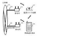
図1は本発明を実施した監視カメラシステムのシステム構成図である。
【0016】
本発明の実施例として、公衆無線通信の無線媒体がIMT−2000、及び近距離無線通信の無線媒体がBluetoothの場合を例にして説明する。
【0017】
図1において、101は公衆網、102、103は公衆網に接続されている通信回線、104、105は通信回線102,103を収容し、無線通信端末、監視カメラ装置と無線通信を行う無線基地局、106は無線通信端末、107は無線通信機能を持った監視カメラ装置である。
【0018】
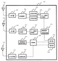
図2は無線通信端末106のブロック図である。
【0019】
図2において、201は無線通信端末本体部、202は送受信を行うRF部、203は電波を送受信するアンテナ、204は送信データの変調及び、受信データの復調を行う変復調部、205はIMT−2000のレイヤ1からレイヤ3までの送信信号処理を行う送信処理部、206はIMT−2000のレイヤ1からレイヤ3までの受信信号処理を行う受信処理部、207はデータ通信を行うさいのデータの誤り検出、訂正処理を行うデータ通信処理部、208は各種の制御処理を行う制御部、209はBluetoothの送受信を行うRF部、210は電波を送受信するアンテナ、211はBluetoothの送信データの変調及び、受信データの復調を行う変復調、及びその他のベースバンド信号処理を行うベースバンド処理部、212はBluetoothでデータ通信を行うさいのデータの誤り検出、訂正処理を行うデータ通信処理部、213は監視カメラ装置107と制御信号の通信を行う制御信号通信処理部、214は圧縮された画像信号の伸張処理を行う画像信号伸張処理部、215はGPS受信部、216は通信衛星からのGPS信号を受信するためのアンテナ、217はGPS受信部215で受信したGPS信号から位置情報を算出する位置算出部、218は無線通信端末の操作部、219は無線通信端末の表示部である。
【0020】
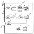
図3は監視カメラ装置107のブロック図である。
【0021】
図3において、301は監視カメラ装置本体部、302は送受信を行うRF部、303は電波を送受信するアンテナ、304は送信データの変調及び、受信データの復調を行う変復調部、305はIMT−2000のレイヤ1からレイヤ3までの送信信号処理を行う送信処理部、306はIMT−2000のレイヤ1からレイヤ3までの受信信号処理を行う受信処理部、307はデータ通信を行うさいのデータの誤り検出、訂正処理を行うデータ通信処理部、308は各種の制御処理を行う制御部、309はBluetoothの送受信を行うRF部、310は電波を送受信するアンテナ、311はBluetoothの送信データの変調及び、受信データの復調を行う変復調、及びその他のベースバンド信号処理を行うベースバンド処理部、312はBluetoothでデータ通信を行うさいのデータの誤り検出、訂正処理を行うデータ通信処理部、313は無線通信端末106と制御信号の通信を行う制御信号通信処理部、314は画像信号の圧縮処理を行う画像信号圧縮処理部、315はレンズ、316はレンズに入力された撮像を画像入力信号として処理して、画像信号圧縮処理部314で処理できる画像信号に変換処理する画像入力処理部である。
【0022】
次に本発明の実施例の動作について説明する。
【0023】
図4は、本発明の実施例を説明するための動作フロー図である。
【0024】
ここでは、一例として、監視カメラ装置107は無線通信端末操作者の自宅の中に設置されていて、操作部218の所定の操作により、操作者の自宅玄関前の位置が設定され、この情報を制御部208で管理している状態として説明する。
【0025】
無線通信端末106は常にGPS受信部215の受信した信号をもとに、位置算出部217で位置情報を算出している(S401)。
【0026】
GPS受信部215の受信した信号をもとに、位置算出部217で算出した位置情報が、自宅玄関前になった事を検出すると(S402)、制御部208はその旨を制御信号通信処理部213に通知する。制御信号通信処理部213は監視カメラ装置107に発呼するように送信処理部205、受信処理部206を制御する。
【0027】
監視カメラ装置107に対して発呼して(S403)、監視カメラ装置107が着信すると(S404)、監視カメラ装置107は無線通信端末106からの着信であるかを調べるため、送信されてきた発信者番号を確認する。なお、ここでは、あらかじめ無線通信端末106の発信者番号が登録されているとして説明する。
【0028】
そして、無線通信端末106からの着信であれば(S405)、無線通信端末106からの制御データの受信待ちになる。
【0029】
次に無線通信端末106は監視カメラ装置107が着信に応答した事を検出すると(S406)、制御信号通信処理部213は監視カメラ装置107にBluetooth通信部の動作起動要求の制御信号を送る(S407)。
【0030】
監視カメラ装置107では、制御信号通信処理部213がこの制御信号を受信したことを検出すると(S408)、その旨を制御部308に通知する。制御部308はBluetoothの通信部であるRF部309、ベースバンド処理部311、データ通信処理部312が所定の時間動作するように制御する(S409)。
【0031】
次に操作者が画像通信を行うために所定の操作を行うと、制御部208はBluetoothの通信部であるRF部209、ベースバンド処理部211、データ通信処理部212が所定の時間動作するように制御する。
【0032】
そして、無線通信端末106からBluetoothによる無線通信で、監視カメラ装置107に画像送信要求のコマンド信号を送る(S410)。監視カメラ装置107はこの信号を受信すると、撮像している画像信号をBluetoothによる無線通信により、無線通信端末106に送る(S411)。無線通信端末106はこの画像信号を受信して、表示部219に順次、表示する(S412)。
【0033】
本実施例では監視カメラ装置107において、無線通信端末106からの着信であるかを調べるために、発信者番号の確認をしたが、別の方法、例えばパスワード送信等でも構わない。
【0034】
また、無線通信端末106の所定の操作により、無線通信端末106の制御部208は、Bluetoothの通信部であるRF部209、ベースバンド処理部211、データ通信処理部212が所定の時間動作するように制御する代わりに、無線通信端末106が所定の位置になった時に、制御部208がBluetoothの通信部であるRF部209、ベースバンド処理部211、データ通信処理部212が所定の時間動作するように制御するようにしても良い。
【0035】
(他の実施例)
上記実施例では、無線通信の媒体としてIMT−2000を用いたが、他の無線通信の媒体でも全く同様な動作ができ、同様な効果がある。
【0036】
【発明の効果】
以上説明したように、本発明によると、公衆無線基地局と無線通信回線を介して通信する画像通信機能を有する無線通信端末と無線監視カメラ装置からなる監視カメラシステムにおいて、前記無線通信端末に、近距離無線通信手段と、位置情報取得手段と、前記無線監視カメラ装置に制御信号を送信する制御信号送信手段と、前記無線通信端末が所定の位置にいることを検出して、前記制御信号送信手段から前記制御信号を送信させる制御手段を設け、前記無線監視カメラ装置に、近距離無線通信手段と、前記無線通信端末から送信される制御信号を受信する制御信号受信手段と、前記制御信号を受信すると、前記近距離無線通信手段を所定の時間動作するように制御する制御手段を設け、さらに前記無線通信端末に前記無線通信端末の所定の操作により、前記近距離無線通信手段を所定の時間動作するように制御する制御手段を設けたので、無線通信端末が所定の位置にいる場合は、簡単な操作で通信料金を必要とせずに近距離無線通信手段を使用して画像を見ることができる。そして、特に無線監視カメラ装置の消費電力も削減できる。そのため、無線監視カメラ装置が長時間のバッテーリー動作が可能になり、使用形態によっては電源コードが必要なくなることが多くなり、設置が簡単になる。
【0037】
また、前記無線通信端末に、前記無線通信端末が所定の位置にいることを検出した場合は、前記近距離無線通信手段を所定の時間動作するように制御する制御手段を設けたので、さらに簡単な操作で通信料金を必要とせずに近距離無線通信手段を使用して画像を見ることができる。
【0038】
以上のような極めて優れた効果がある。
【図面の簡単な説明】
【図1】本発明を実施したシステムの構成図
【図2】無線通信端末のブロック図
【図3】監視カメラ装置のブロック図
【図4】本発明の実施例を説明するための動作フロー図
【符号の説明】
101 公衆網
102、103 通信回線
104、105 無線基地局
106 無線通信端末
107 監視カメラ装置
201 無線通信端末本体部
202 RF部
203 アンテナ
204 変復調部
205 送信処理部
206 受信処理部
207 データ通信処理部
208 制御部
209 RF部
210 アンテナ
211 ベースバンド処理部
212 データ通信処理部
213 制御信号通信処理部
214 画像信号伸張処理部
215 GPS受信部
216 アンテナ
217 位置算出部
218 操作部
219 表示部
301 監視カメラ装置本体部
302 RF部
303 アンテナ
304 変復調部
305 送信処理部
306 受信処理部
307 データ通信処理部
308 制御部
309 RF部
310 アンテナ
311 ベースバンド処理部
312 データ通信処理部
313 制御信号通信処理部
314 画像信号圧縮処理部
315 レンズ
316 画像入力処理部[0001]
TECHNICAL FIELD OF THE INVENTION
The present invention relates to a surveillance camera system that uses a wireless communication terminal as an image display terminal.
[0002]
[Prior art]
Conventionally, there has been a surveillance camera system including a wireless communication terminal having an image display function and a surveillance camera device.
[0003]
By the way, there is one that operates a surveillance camera based on collation of a caller number or ID from a wireless communication terminal (for example, see Patent Document 1).
[0004]
[Patent Document 1]
JP 2001-266296 A [0005]
[Problems to be solved by the invention]
However, in the conventional surveillance camera system, installation of the surveillance camera device is troublesome. Further, a communication fee is always charged for a communication means of the monitoring camera device using a public wireless communication line. This is when the operator of the wireless communication terminal displaying the image is near the surveillance camera device, for example, when installing the surveillance camera device in the house and viewing the image from the entrance before entering the house But it costs communication charges. In such a case, it is desired to use another wireless communication means.
[0006]
Further, even in the case where image communication can be performed by two public wireless communication means and another wireless communication means, since the two wireless communication means are operated or the communication means are switched, especially the current consumption of the monitoring camera device, or The operation of the wireless communication terminal is complicated.
[0007]
There were many problems as described above.
[0008]
The present invention has been made by paying attention to the above points, and comprises a position information acquiring unit and a control unit for automatically calling a surveillance camera when a predetermined position is reached in a wireless communication terminal that views a monitoring image. It is another object of the present invention to provide a surveillance camera system including a control unit that operates a short-distance wireless communication unit for a predetermined time in response to an incoming call from the wireless communication terminal.
[0009]
[Means for Solving the Problems]
The present invention can solve the above problem by providing the following configuration.
[0010]
In the invention of claim 1 of the present invention, in a surveillance camera system including a wireless communication terminal having an image communication function of communicating with a public wireless base station via a wireless communication line and a wireless monitoring camera device, the wireless communication terminal includes: Short-range wireless communication means, position information acquisition means, control signal transmission means for transmitting a control signal to the wireless surveillance camera device, and detecting that the wireless communication terminal is at a predetermined position, transmitting the control signal A control means for transmitting the control signal from the means, a short-range wireless communication means, a control signal receiving means for receiving a control signal transmitted from the wireless communication terminal, and the control signal, Control means is provided for controlling the short-range wireless communication means to operate for a predetermined time when receiving.
[0011]
According to a second aspect of the present invention, in the surveillance camera system according to the first aspect, the control means controls the wireless communication terminal to operate the short-range wireless communication means for a predetermined time by a predetermined operation of the wireless communication terminal. Provided.
[0012]
According to a third aspect of the present invention, in the surveillance camera system according to the first aspect, when the wireless communication terminal detects that the wireless communication terminal is at a predetermined position, the short-range wireless communication means operates for a predetermined time. Control means for controlling the operation.
[0013]
According to a fourth aspect of the present invention, in the surveillance camera system according to any one of the first to third aspects, when the wireless communication terminal detects that the wireless communication terminal is at a predetermined position, the wireless communication terminal and the wireless monitoring camera device are connected to each other. Image communication is performed by the distance wireless communication means.
[0014]
According to a fifth aspect of the present invention, in the surveillance camera system according to any one of the first to fourth aspects, the position information acquiring means uses a global positioning system (GPS).
[0015]
BEST MODE FOR CARRYING OUT THE INVENTION
FIG. 1 is a system configuration diagram of a surveillance camera system embodying the present invention.
[0016]
As an embodiment of the present invention, a case will be described as an example where the wireless medium of public wireless communication is IMT-2000 and the wireless medium of short-range wireless communication is Bluetooth.
[0017]
In FIG. 1, 101 is a public network, 102 and 103 are communication lines connected to the public network, 104 and 105 are communication bases that accommodate the communication lines 102 and 103 and perform wireless communication with a wireless communication terminal and a monitoring camera device. A station 106 is a wireless communication terminal, and 107 is a monitoring camera device having a wireless communication function.
[0018]
FIG. 2 is a block diagram of the wireless communication terminal 106.
[0019]
In FIG. 2, 201 is a wireless communication terminal main unit, 202 is an RF unit for transmitting and receiving, 203 is an antenna for transmitting and receiving radio waves, 204 is a modulation and demodulation unit for modulating transmission data and demodulating received data, and 205 is an IMT-2000. A transmission processing unit that performs transmission signal processing from layer 1 to layer 3 of IMT-2000, a reception processing unit that performs reception signal processing from layer 1 to layer 3 of IMT-2000, and a
[0020]
FIG. 3 is a block diagram of the
[0021]
In FIG. 3,
[0022]
Next, the operation of the embodiment of the present invention will be described.
[0023]
FIG. 4 is an operation flowchart for explaining the embodiment of the present invention.
[0024]
Here, as an example, the
[0025]
In the wireless communication terminal 106, the position information is always calculated by the
[0026]
Upon detecting that the position information calculated by the
[0027]
When a call is made to the surveillance camera device 107 (S403), and the
[0028]
If the incoming call is from the wireless communication terminal 106 (S405), the process waits for reception of control data from the wireless communication terminal 106.
[0029]
Next, when the wireless communication terminal 106 detects that the
[0030]
In the
[0031]
Next, when the operator performs a predetermined operation for performing image communication, the
[0032]
Then, a command signal of an image transmission request is sent from the wireless communication terminal 106 to the
[0033]
In this embodiment, the
[0034]
By a predetermined operation of the wireless communication terminal 106, the
[0035]
(Other embodiments)
In the above embodiment, IMT-2000 is used as a medium for wireless communication, but the same operation can be performed with other wireless communication medium, and the same effect can be obtained.
[0036]
【The invention's effect】
As described above, according to the present invention, in a surveillance camera system including a wireless communication terminal having an image communication function of communicating with a public wireless base station via a wireless communication line and a wireless monitoring camera device, the wireless communication terminal includes: Short-range wireless communication means, position information acquisition means, control signal transmission means for transmitting a control signal to the wireless surveillance camera device, and detecting that the wireless communication terminal is at a predetermined position, transmitting the control signal A control means for transmitting the control signal from the means, a short-range wireless communication means, a control signal receiving means for receiving a control signal transmitted from the wireless communication terminal, and the control signal, When receiving, a control means for controlling the short-range wireless communication means to operate for a predetermined time is provided. A control means for controlling the short-range wireless communication means to operate for a predetermined time by an operation is provided, so that when the wireless communication terminal is at a predetermined position, a simple operation does not require a communication fee and the proximity is possible. Images can be viewed using range wireless communication means. In particular, the power consumption of the wireless monitoring camera device can be reduced. Therefore, the wireless surveillance camera device can perform a battery operation for a long time, and depending on the usage form, a power cord is not required in many cases, and installation is simplified.
[0037]
Further, when the wireless communication terminal detects that the wireless communication terminal is at a predetermined position, control means for controlling the short-distance wireless communication means to operate for a predetermined time is provided, so that it is simpler. The image can be viewed using the short-range wireless communication means without requiring a communication fee by a simple operation.
[0038]
There are extremely excellent effects as described above.
[Brief description of the drawings]
FIG. 1 is a block diagram of a system embodying the present invention. FIG. 2 is a block diagram of a wireless communication terminal. FIG. 3 is a block diagram of a monitoring camera device. FIG. 4 is an operation flow diagram for explaining an embodiment of the present invention. [Explanation of symbols]
101 public network 102, 103 communication line 104, 105 wireless base station 106
Claims (5)
前記無線通信端末に、近距離無線通信手段と、位置情報取得手段と、前記無線監視カメラ装置に制御信号を送信する制御信号送信手段と、前記無線通信端末が所定の位置にいることを検出して、前記制御信号送信手段から前記制御信号を送信させる制御手段を設け、
前記無線監視カメラ装置に、近距離無線通信手段と、前記無線通信端末から送信される制御信号を受信する制御信号受信手段と、前記制御信号を受信すると、前記近距離無線通信手段を所定の時間動作するように制御する制御手段を設けたことを特徴とする監視カメラシステム。In a monitoring camera system including a wireless communication terminal having an image communication function for communicating with a public wireless base station via a wireless communication line and a wireless monitoring camera device,
The wireless communication terminal includes a short-range wireless communication unit, a position information acquiring unit, a control signal transmitting unit that transmits a control signal to the wireless monitoring camera device, and detecting that the wireless communication terminal is at a predetermined position. A control means for transmitting the control signal from the control signal transmitting means is provided,
The wireless monitoring camera device includes a short-range wireless communication unit, a control signal receiving unit configured to receive a control signal transmitted from the wireless communication terminal, and receiving the control signal. A surveillance camera system, comprising a control unit for controlling operation.
前記無線通信端末に前記無線通信端末の所定の操作により、前記近距離無線通信手段を所定の時間動作するように制御する制御手段を設けたことを特徴とする請求項1記載の監視カメラシステム。In the surveillance camera system,
The surveillance camera system according to claim 1, wherein the wireless communication terminal is provided with control means for controlling the short-range wireless communication means to operate for a predetermined time by a predetermined operation of the wireless communication terminal.
前記無線通信端末に、前記無線通信端末が所定の位置にいることを検出した場合は、前記近距離無線通信手段を所定の時間動作するように制御する制御手段を設けたことを特徴とする請求項1記載の監視カメラシステム。In the surveillance camera system,
The wireless communication terminal further comprises control means for controlling the short-range wireless communication means to operate for a predetermined time when the wireless communication terminal detects that the wireless communication terminal is at a predetermined position. Item 2. The surveillance camera system according to Item 1.
前記無線通信端末が所定の位置にいることを検出した場合は、前記無線通信端末と前記無線監視カメラ装置は前記近距離無線通信手段により画像通信を行うことを特徴とする請求項1ないし3いずれか記載の監視カメラシステム。In the surveillance camera system,
4. The wireless communication terminal and the wireless monitoring camera device perform image communication by the short-range wireless communication unit when detecting that the wireless communication terminal is at a predetermined position. The surveillance camera system according to the above.
前記位置情報取得手段は全地球測位システム(GPS)であることを特徴とする請求項1ないし4いずれか記載の監視カメラシステム。In the surveillance camera system,
The surveillance camera system according to any one of claims 1 to 4, wherein the position information acquisition unit is a global positioning system (GPS).
Priority Applications (1)
| Application Number | Priority Date | Filing Date | Title |
|---|---|---|---|
| JP2002366705A JP2004200998A (en) | 2002-12-18 | 2002-12-18 | Monitoring camera system |
Applications Claiming Priority (1)
| Application Number | Priority Date | Filing Date | Title |
|---|---|---|---|
| JP2002366705A JP2004200998A (en) | 2002-12-18 | 2002-12-18 | Monitoring camera system |
Publications (1)
| Publication Number | Publication Date |
|---|---|
| JP2004200998A true JP2004200998A (en) | 2004-07-15 |
Family
ID=32763832
Family Applications (1)
| Application Number | Title | Priority Date | Filing Date |
|---|---|---|---|
| JP2002366705A Withdrawn JP2004200998A (en) | 2002-12-18 | 2002-12-18 | Monitoring camera system |
Country Status (1)
| Country | Link |
|---|---|
| JP (1) | JP2004200998A (en) |
Cited By (4)
| Publication number | Priority date | Publication date | Assignee | Title |
|---|---|---|---|---|
| JPWO2006025241A1 (en) * | 2004-08-31 | 2008-05-08 | シャープ株式会社 | Data transmission device, data reception device, server, transmission / reception device, data sharing system, data transmission program, data reception program, data sharing program, data transmission / reception program, and computer-readable recording medium |
| JP2008252212A (en) * | 2007-03-29 | 2008-10-16 | Fujifilm Corp | Information communication system and method |
| US7650144B2 (en) | 2005-03-01 | 2010-01-19 | Omron Corporation | Monitoring control apparatus, monitoring system, monitoring method, wireless communication apparatus and wireless communication system |
| JP2019017082A (en) * | 2018-09-06 | 2019-01-31 | キヤノンマーケティングジャパン株式会社 | Management server, system, control method thereof, and program |
-
2002
- 2002-12-18 JP JP2002366705A patent/JP2004200998A/en not_active Withdrawn
Cited By (4)
| Publication number | Priority date | Publication date | Assignee | Title |
|---|---|---|---|---|
| JPWO2006025241A1 (en) * | 2004-08-31 | 2008-05-08 | シャープ株式会社 | Data transmission device, data reception device, server, transmission / reception device, data sharing system, data transmission program, data reception program, data sharing program, data transmission / reception program, and computer-readable recording medium |
| US7650144B2 (en) | 2005-03-01 | 2010-01-19 | Omron Corporation | Monitoring control apparatus, monitoring system, monitoring method, wireless communication apparatus and wireless communication system |
| JP2008252212A (en) * | 2007-03-29 | 2008-10-16 | Fujifilm Corp | Information communication system and method |
| JP2019017082A (en) * | 2018-09-06 | 2019-01-31 | キヤノンマーケティングジャパン株式会社 | Management server, system, control method thereof, and program |
Similar Documents
| Publication | Publication Date | Title |
|---|---|---|
| CN107409306B (en) | Communication device, communication system, and non-transitory computer-readable medium | |
| US8050197B2 (en) | Connection controller, communication system, and connection control method | |
| CN108924364B (en) | Message reminding method, mobile terminal and computer readable storage medium | |
| EP1168716A2 (en) | Apparatus and system for radio communication, and stationary station | |
| JPH09178833A (en) | Terminal device | |
| EP1720328A1 (en) | Apparatus and method for displaying information in Bluetooth communication mode of wireless terminal | |
| JP2005513975A (en) | Mobile device power savings | |
| EP1530342A2 (en) | Mobile communication terminal, mobile communication system and content delivery method | |
| JP2002218503A (en) | Communication system and mobile terminal | |
| KR101626465B1 (en) | Apparatus and method for connecting the access point in portable communication system | |
| JP2004200998A (en) | Monitoring camera system | |
| US20040203356A1 (en) | Master communication apparatus used in radio lan system, and control method and control program of master communication apparatus | |
| US20180343379A1 (en) | Surveillance camera system | |
| JP3390841B2 (en) | Mobile phone equipment | |
| JP2004312639A (en) | Location display system and location display device using the same | |
| JP3092189B2 (en) | Wireless telephone equipment | |
| JP3610829B2 (en) | Door phone system | |
| JP2002152392A (en) | Intercommunication system | |
| JPH09247737A (en) | Position information detection system | |
| JP2009060270A (en) | Broadcast communication system of radio communication system | |
| JP2001224010A (en) | Monitor camera system | |
| US20030179722A1 (en) | Master communication apparatus used in radio lan system, and control method and control program of master communication apparatus | |
| JPH07177055A (en) | Radio terminal equipment | |
| JPH11243575A (en) | Mobile radio communication equipment | |
| JP2000197161A (en) | Adaptor and electronic camera system provided with the adaptor |
Legal Events
| Date | Code | Title | Description |
|---|---|---|---|
| A300 | Application deemed to be withdrawn because no request for examination was validly filed |
Free format text: JAPANESE INTERMEDIATE CODE: A300 Effective date: 20060307 |