JP2004198715A - Automatic focusing device - Google Patents
Automatic focusing device Download PDFInfo
- Publication number
- JP2004198715A JP2004198715A JP2002366846A JP2002366846A JP2004198715A JP 2004198715 A JP2004198715 A JP 2004198715A JP 2002366846 A JP2002366846 A JP 2002366846A JP 2002366846 A JP2002366846 A JP 2002366846A JP 2004198715 A JP2004198715 A JP 2004198715A
- Authority
- JP
- Japan
- Prior art keywords
- signal
- frequency signal
- gain
- color
- focus
- Prior art date
- Legal status (The legal status is an assumption and is not a legal conclusion. Google has not performed a legal analysis and makes no representation as to the accuracy of the status listed.)
- Granted
Links
Images


Abstract
Description
【0001】
【発明の属する技術分野】
本発明は、撮像装置における自動焦点調節技術に関するものである。
【0002】
【従来の技術】
一般に、デジタルカメラやビデオカメラのように二次元撮像素子を有する電子撮像装置では、被写体の映像信号により画面の鮮鋭度を検出し、この鮮鋭度が最大になるようにフォーカシングレンズの位置を制御してピントを合わせる方法が用いられている。この鮮鋭度の検出方法としては、バンドパスフィルタにより抽出された映像信号の高周波成分の強度や、微分回路等により映像信号を微分して得られた被写体のエッジ部におけるぼけ幅の検出強度が用いられる。
【0003】
通常の被写体を撮影した場合、この鮮鋭度は、ピントがぼけている状態では小さく、ピントが合うにつれて大きくなり、ピントが完全に合った状態で最大値に達する。従来、フォーカシングレンズの制御には、この鮮鋭度が小さい場合に鮮鋭度が大きくなる方向にフォーカシングレンズをできるだけ速く移動させ、大きくなるにつれてこの速度を徐々に遅くし、鮮鋭度の山の頂上でフォーカシングレンズを精度良く停止させるいわゆる山登り法オートフォーカス(以下山登りAFと略す)が一般に用いられている。
【0004】
また、もうひとつの別の制御手段として、本撮影前に、近端から無限端までフォーカスレンズ位置を徐々に動かし、その度に被写体を撮影し、その複数枚の画像を鮮鋭度検出手段に通して得た鮮鋭度のうち、もっとも鮮鋭度が大きくなる画像が得られたフォーカスレンズ位置を合焦ポイントとする全スキャン方式AFが用いられている。
【0005】
【発明が解決しようとする課題】
しかしながら、上記の従来のAF(オートフォーカス)方法では、例えば通常の被写体として最も一般的な人物等を撮影した場合に、例えば測距エリア内に顔アップの映像があった場合、顔は、建物など構造物と異なり平坦であるため、測距エリアの映像信号が低コントラスト状態となり、フォーカシングレンズを合焦点において精度良く停止させることができない問題点がある。これは、主に、フォーカシングレンズの移動量に対して低コントラスト被写体の鮮鋭度信号の変化が少ないためである。
【0006】
従って、本発明は上述した課題に鑑みてなされたものであり、その目的は、人物等を撮影した場合でも精度のよいオートフォーカスを可能とすることである。
【0007】
【課題を解決するための手段】
上述した課題を解決し、目的を達成するために、本発明に係わる自動焦点調節装置は、被写体像の撮像素子上への合焦状態を調節するためのフォーカスレンズと、該フォーカスレンズを所定のステップで移動させながら、各ステップ毎に被写体像を撮影して、複数枚の画像信号を生成する撮像手段と、該撮像手段の出力信号から輝度信号と色信号を作成する信号処理手段と、前記輝度信号から第1の高周波信号を検出する高周波信号検出手段と、前記色信号から肌色を検出する肌色検出手段と、該肌色検出手段の検出結果に基づいて、前記第1の高周波信号に乗算するゲインを決定するゲイン決定手段と、該ゲイン決定手段により決定されたゲインを前記第1の高周波信号に乗算して、第2の高周波信号を出力する乗算手段と、前記第2の高周波信号に基づいて前記フォーカスレンズの合焦位置を判定する合焦位置判定手段とを具備することを特徴としている。
【0008】
【発明の実施の形態】
以下、本発明の好適な一実施形態について説明する。
【0009】
まず、本実施形態の概要について説明する。
【0010】
本実施形態の自動焦点調節装置は、被写体像の撮像素子上への合焦状態を調節するためのフォーカスレンズと、該フォーカスレンズを所定のステップで移動させながら、各ステップ毎に被写体像を撮影して、複数枚の画像信号を生成する撮像手段と、該撮像手段の出力信号から輝度信号と色信号を作成する信号処理手段と、前記輝度信号から第1の高周波信号を検出する高周波信号検出手段と、前記色信号から肌色を検出する肌色検出手段と、該肌色検出手段の検出結果に基づいて、前記第1の高周波信号に乗算するゲインを決定するゲイン決定手段と、該ゲイン決定手段により決定されたゲインを前記第1の高周波信号に乗算して、第2の高周波信号を出力する乗算手段と、前記第2の高周波信号に基づいて前記フォーカスレンズの合焦位置を判定する合焦位置判定手段とを備える。
【0011】
また、本実施形態の自動焦点調節装置において、前記高周波信号検出手段は、バンドパスフィルタを備え、該バンドパスフィルタの出力の絶対値のピーク値を出力することが好ましい。
【0012】
また、本実施形態の自動焦点調節装置において、前記高周波信号検出手段は、バンドパスフィルタを備え、該バンドパスフィルタの出力の絶対値の和を出力することが好ましい。
【0013】
また、本実施形態の自動焦点調節装置において、前記肌色検出手段は、前記撮像素子からの色信号から色相角を算出し、予め設定した肌色の色相角度範囲内にあれば肌色であると検出することが好ましい。
【0014】
また、本実施形態の自動焦点調節装置において、前記ゲイン決定手段は、前記肌色検出手段より得られた被写体色相角と、予め設定した肌色色相角との差分に基づいて補正ゲインを算出することが好ましい。
【0015】
また、本実施形態の自動焦点調節方法は、被写体像の撮像素子上への合焦状態を調節するためのフォーカスレンズを所定のステップで移動させながら、各ステップ毎に被写体像を撮影して、複数枚の画像信号を生成する撮像工程と、該撮像工程における出力信号から輝度信号と色信号を作成する信号処理工程と、前記輝度信号から第1の高周波信号を検出する高周波信号検出工程と、前記色信号から肌色を検出する肌色検出工程と、該肌色検出工程における検出結果に基づいて、前記第1の高周波信号に乗算するゲインを決定するゲイン決定工程と、該ゲイン決定工程において決定されたゲインを前記第1の高周波信号に乗算して、第2の高周波信号を出力する乗算工程と、前記第2の高周波信号に基づいて前記フォーカスレンズの合焦位置を判定する合焦位置判定工程とを備える。
【0016】
また、本実施形態の自動焦点調節方法において、前記高周波信号検出工程では、バンドパスフィルタの出力の絶対値のピーク値を出力することが好ましい。
【0017】
また、本実施形態の自動焦点調節方法において、前記高周波信号検出工程では、バンドパスフィルタの出力の絶対値の和を出力することが好ましい。
【0018】
また、本実施形態の自動焦点調節方法において、前記肌色検出工程では、前記撮像素子からの色信号から色相角を算出し、予め設定した肌色の色相角度範囲内にあれば肌色であると検出することが好ましい。
【0019】
また、本実施形態の自動焦点調節方法において、前記ゲイン決定工程では、前記肌色検出工程において得られた被写体色相角と、予め設定した肌色色相角との差分に基づいて補正ゲインを算出することが好ましい。
【0020】
また、本実施形態のプログラムは、上記の自動焦点調節方法をコンピュータに実行させる。
【0021】
以下、本発明の一実施形態について、図面を参照して具体的に説明する。
【0022】
図1は一実施形態の撮像装置におけるAF(オートフォーカス)制御ブロックの回路の概略図である。この図を用いてAF装置のおおまかな動作説明を行なう。
【0023】
被写体(不図示)からの光は、フォーカスレンズ群を含むレンズ101をとおり、CCD撮像素子102に結像される。CCD102からの出力信号は、ホワイトバランス(WB)ブロック103にて各色フィルタのゲインが調整される。ホワイトバランスブロック103から出力された信号は、Y−LPFブロック104にて、水平垂直に適当なLPF(ローパスフィルタ)がかけられ帯域制限され、各水平ライン毎に、BPF(バンドパスフィルタ)回路105にて高周波信号が検出される。次に各水平ライン毎にBPF回路105の出力信号のピーク値がピークホールド回路106にて出力され、これが第1の高周波信号となる。
【0024】
一方、ホワイトバランスブロック103から出力された信号は色変換MTX(マトリックス)回路107にて色差信号Cr、Cbに変換され、肌色相角検出ブロック108において肌色か肌色でないか検出される。肌色相角検出ブロック108の出力によって、第1の高周波信号にかけるゲインが補正ゲイン算出ブロック109にて決定される。
【0025】
次に、第1の高周波信号が乗算器111において補正され第2の高周波信号となり、一旦メモリ112に記録される。予め設定された測距エリア内の全ての水平ラインにおいて上述の高周波信号が作られメモリに記録され、全ラインの高周波信号の和をとる。
【0026】
フォーカスレンズ駆動部114は全てのAFステップポイント(フォーカスレンズの動きえるポイント)にて、上記高周波信号の和を算出した後、合焦位置判定ブロック113にて最も高周波信号の和が大きいステップポイントを合焦位置と判定し、フォーカスレンズ駆動部114にてフォーカスレンズを合焦位置に動かす。その後、本撮影(本明細書では説明しない)をはじめる。
【0027】
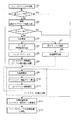
図2は、AF装置の動作フローチャートである。以下、図1及び図2を参照して、AF装置の動作の詳細を説明する。
【0028】
(ステップS1)
シャッターが半押しされると、フォーカスレンズ101の位置を駆動するフォーカスレンズ駆動部114が、フォーカスレンズを近端から無限端まで予め設定されたステップで動かす。
【0029】
(ステップS2)
各ステップ(フォーカスレンズの各移動位置)毎に、被写体を撮影し、図6のように予め設定された測距エリアの撮像信号を撮像素子102から読みだす。(以下、各ステップ毎に撮影された信号すべてに対して実施する)
(ステップS3)
ホワイトバランスブロック103にて各色フィルタ毎にホワイトバランスゲインがかけられる。
【0030】
(ステップS4)
輝度信号作成ブロック(Y−LPF回路)104にて、色フィルタの感度ばらつき補正のために、例えば
【0031】
【数1】

【0032】
(ステップS5)
輝度信号作成ブロック104からの輝度信号に、測距エリア1ライン毎にバンドパスフィルタ105をかける。なお、本実施形態では、回路を簡略化するために、1ライン毎のバンドパスフィルタとしているが、ディレイラインを設定して3ライン、5ラインとライン数を増やし、2次元のバンドパスフィルタをかけるほうがより正確なコントラスト信号が得られる。
【0033】
(ステップS6)
図5のようにバンドパスフィルタ後の信号より、PeakHold回路106により回路絶対値のピーク信号を保持し、測距エリア内の全ての水平ラインのピーク信号の和を算出し、これを第1のコントラスト信号とする。なお、ピーク信号の和でなく、バンドパスフィルタ出力の絶対値の積分値を用いてもよい。
【0034】
(ステップS7)
一方、色信号作成ブロックにて、ホワイトバランス後の信号を、色マトリクス回路107にてR−Y、B−Y信号に変換する。
【0035】
(ステップS8)
測距エリア内の色差信号を加算平均する。
【0036】
次に、本実施形態の特徴点である、コントラスト信号補正部の説明をする。
【0037】
ステップS6からの第1のコントラスト信号と、ステップS8からの色差信号を用いて、コントラスト補正を実施する。これは、被写体が人の顔などの場合は、コントラスト信号が弱くなってしまうのを防ぐためである。色差信号から肌色を検出し、肌色と判定された場合は、第1のコントラスト信号を強調するゲインをかける。以下に、このコントラスト信号補正部を詳細に説明する。
【0038】
(ステップS9)
測距エリア内の色差信号の平均(aveR−Y、aveB−Y)を算出し、
ChromaHue=tan-1((aveR−Y)/(aveB−Y))
の式で色相角(ChromaHue)を作成する。この演算は、肌色相角検出回路108により行なわれる。
【0039】
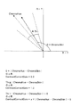
(ステップS10)
図3のような色差空間上で、予め設定した肌色の色相角(ChromaSkin)とChromaHueが同じ場合にGainMAXとし、肌色の色相角から離れるにつれ補正ゲイン(ContrastCorrectGain)を小さくし、予め設定した色相角(θTh)以上離れるとゲインをGainMin(=1)とするコントラスト補正ゲインを出力する。この演算は、補正ゲイン算出回路109により行なわれる。
【0040】
例えば、
0=|ChromaHue−ChromaSkin|
のとき、
ContrastCorrectGain=GainMAX(=2.0)
θTh≦|ChromaHue−ChromaSkin|
のとき、
ContrastCorrectGain=GainMin(=1.0)
θTh>|ChromaHue−ChromaSkin|>0
のとき、
ContrastCorrectGain=a×|ChromaHue−ChromaSkin|+b
の線形1次式で算出する。
【0041】
更に、本実施形態では、よりAF検出の精度を向上させるために、コントラスト補正ゲインの最大値GainMAXを、フォーカスレンズ位置によって変化させる。これは、主に人物撮影などの場合、被写体は比較的近い距離に存在する場合が多いため、AFステップの近側のGainMAXを無限側のGainMAXより大きい値に設定する。例えば、図4のような特性をもつグラフを用いて、AFステップ位置によってGainMAXを変化させる。
【0042】
(ステップS11)
コントラスト信号補正部(色変換MTX回路107、肌色相角検出回路108、補正ゲイン算出回路109を備える)より算出された補正ゲインをコントラスト検出部(Y−LPF回路104、BPF105、PeakHold回路106を備える)からの第1のコントラスト信号にかける(乗算器111により行なわれる)ことにより肌補正後の第2のコントラスト信号を作成する。
【0043】
(ステップS12)
複数のAFステップ位置によって得られた第2のコントラスト信号のピーク値を検出し、合焦位置判定回路113によりそのポイントを合焦ポイントと判断し、フォーカスレンズ101を移動する。なお、コントラスト信号のピーク信号ではなく、ピークから任意の数のステップポイントを選択し、その平均を合焦位置と判断してもよい。
【0044】
上述のように、本実施形態によれば、人物等を撮影して顔面の映像が低コントラスト状態になった場合でも、肌色の色相角を判別し、肌と判定されたコントラスト信号を強調するコントラスト補正部を備えているため、より正確なオートフォーカスが実現できる。
【0045】
また、本実施形態では、ステップS8、S9により、測距エリア内の色差信号の平均値を算出し、その色差信号からの色相角でコントラスト補正ゲインを求め、各ステップ毎に算出されたコントラスト信号を補正しているが、各ステップの各水平ライン毎に求めたバンドパスピーク信号に、各ライン毎に算出した色相角よる肌補正ゲインをかけ、その補正コントラスト信号の積分値(測距エリア内)を用いて合焦位置を判定してもよい。
【0046】
以上説明したように、上記の実施形態によれば、予め決められたステップでフォーカスレンズを近側から無限側まで動かしながら被写体を複数枚撮影し、その撮像信号から輝度信号と色信号を作成し、輝度信号より合焦判定用の高周波信号を検出し、色信号から被写体が肌色であった場合に、前記合焦用高周波信号のゲインをアップする構成をとるため、人物の顔アップなどの場合に、合焦判定用高周波信号の振幅を大きくすることが可能となり、より正確なオートフォーカスが実現できる。
【0047】
【他の実施形態】
本発明は、複数の機器から構成されるシステムに適用しても良いし、また、単体の機器から成る装置に適用しても良いしLANなどのネットワークを介して処理が行われるシステムに適用しても良い。
【0048】
また、各実施形態の目的は、前述した実施形態の機能を実現するソフトウェアのプログラムコードを記録した記憶媒体(または記録媒体)を、システムあるいは装置に供給し、そのシステムあるいは装置のコンピュータ(またはCPUやMPU)が記憶媒体に格納されたプログラムコードを読み出し実行することによっても、達成されることは言うまでもない。この場合、記憶媒体から読み出されたプログラムコード自体が前述した実施形態の機能を実現することになり、そのプログラムコードを記憶した記憶媒体は本発明を構成することになる。また、コンピュータが読み出したプログラムコードを実行することにより、前述した実施形態の機能が実現されるだけでなく、そのプログラムコードの指示に基づき、コンピュータ上で稼働しているオペレーティングシステム(OS)などが実際の処理の一部または全部を行い、その処理によって前述した実施形態の機能が実現される場合も含まれることは言うまでもない。
【0049】
さらに、記憶媒体から読み出されたプログラムコードが、コンピュータに挿入された機能拡張カードやコンピュータに接続された機能拡張ユニットに備わるメモリに書込まれた後、そのプログラムコードの指示に基づき、その機能拡張カードや機能拡張ユニットに備わるCPUなどが実際の処理の一部または全部を行い、その処理によって前述した実施形態の機能が実現される場合も含まれることは言うまでもない。
【0050】
本発明を上記記憶媒体に適用する場合、その記憶媒体には、先に説明したフローチャートに対応するプログラムコードが格納されることになる。
【0051】
【発明の効果】
以上説明したように、本発明によれば、人物等を撮影した場合でも精度のよいオートフォーカスを可能とすることができる。
【図面の簡単な説明】
【図1】本発明の一実施形態におけるAF制御ブロックの回路の概略図である。
【図2】一実施形態の合焦装置の動作フローチャートである。
【図3】肌色判定および補正ゲイン設定を示した図である。
【図4】MAXゲインの設定例を示した図である。
【図5】バンドパスフィルタの出力波形を示す図である。
【図6】撮像エリアと測距エリアを示した図である。
【符号の説明】
101 フォーカスレンズ群
102 CCD撮像素子
103 ホワイトバランス回路
104 輝度ノッチ回路
105 バンドパスフィルタ
106 ピークホールド、高周波信号検出回路
107 色変換マトリクス回路
108 色相角検出回路
109 高周波信号補正ゲイン算出回路
111 ゲイン回路(乗算回路)
112 メモリ
113 合焦位置判定ブロック
114 フォーカスレンズ駆動部[0001]
TECHNICAL FIELD OF THE INVENTION
The present invention relates to an automatic focus adjustment technology in an imaging device.
[0002]
[Prior art]
Generally, in an electronic imaging device having a two-dimensional imaging device such as a digital camera or a video camera, the sharpness of a screen is detected based on a video signal of a subject, and the position of a focusing lens is controlled so that the sharpness is maximized. A method of adjusting the focus is used. As a method of detecting the sharpness, the intensity of the high-frequency component of the video signal extracted by the band-pass filter or the detection intensity of the blur width at the edge portion of the subject obtained by differentiating the video signal by a differentiating circuit or the like is used. Can be
[0003]
When a normal subject is photographed, the sharpness is small when the subject is out of focus, increases as the subject is focused, and reaches a maximum value when the subject is completely focused. Conventionally, focusing lens control involves moving the focusing lens as fast as possible in the direction where sharpness increases when this sharpness is low, gradually decreasing this speed as the sharpness increases, and focusing at the top of the sharpness peak. A so-called hill-climbing autofocus (hereinafter abbreviated as hill-climbing AF) for stopping a lens with high accuracy is generally used.
[0004]
As another control means, before the actual photographing, the focus lens position is gradually moved from the near end to the infinity end, the subject is photographed each time, and the plurality of images are passed through the sharpness detecting means. All-scan AF is used in which the focus point is the position of the focus lens at which the image with the highest sharpness is obtained from among the sharpnesses obtained by the above method.
[0005]
[Problems to be solved by the invention]
However, in the above-mentioned conventional AF (autofocus) method, for example, when the most common person or the like is photographed as a normal subject, for example, when there is a face-up image in the distance measurement area, Unlike a structure such as a flat structure, the video signal in the distance measurement area is in a low contrast state, and there is a problem that the focusing lens cannot be stopped accurately at the focal point. This is mainly because there is little change in the sharpness signal of the low-contrast subject with respect to the moving amount of the focusing lens.
[0006]
Therefore, the present invention has been made in view of the above-described problem, and an object of the present invention is to enable highly accurate autofocus even when a person or the like is photographed.
[0007]
[Means for Solving the Problems]
In order to solve the above-described problems and achieve the object, an automatic focus adjustment device according to the present invention includes a focus lens for adjusting a focus state of a subject image on an imaging device, and a focus lens for adjusting a focus lens to a predetermined state. Imaging means for photographing a subject image for each step while moving in steps and generating a plurality of image signals; signal processing means for creating a luminance signal and a color signal from output signals of the imaging means; High-frequency signal detection means for detecting a first high-frequency signal from a luminance signal; skin-color detection means for detecting a skin color from the color signal; and multiplying the first high-frequency signal based on a detection result of the skin-color detection means. Gain determining means for determining a gain; multiplying means for multiplying the first high-frequency signal by the gain determined by the gain determining means to output a second high-frequency signal; Is characterized by comprising a determining the focus position determination unit focus position of the focus lens based on the wave signal.
[0008]
BEST MODE FOR CARRYING OUT THE INVENTION
Hereinafter, a preferred embodiment of the present invention will be described.
[0009]
First, an outline of the present embodiment will be described.
[0010]
The automatic focus adjustment device of the present embodiment includes a focus lens for adjusting a focus state of a subject image on an image sensor, and captures a subject image for each step while moving the focus lens in predetermined steps. Imaging means for generating a plurality of image signals; signal processing means for generating a luminance signal and a color signal from output signals of the imaging means; and high-frequency signal detection for detecting a first high-frequency signal from the luminance signal Means, skin color detecting means for detecting a skin color from the color signal, gain determining means for determining a gain by which the first high-frequency signal is multiplied based on a detection result of the skin color detecting means, and gain determining means Multiplying means for multiplying the first high-frequency signal by the determined gain to output a second high-frequency signal; and a focusing position of the focus lens based on the second high-frequency signal. And a focus position determining means for determining.
[0011]
Further, in the automatic focusing apparatus of the present embodiment, it is preferable that the high-frequency signal detecting means includes a band-pass filter, and outputs a peak value of an absolute value of an output of the band-pass filter.
[0012]
Further, in the automatic focusing apparatus of the present embodiment, it is preferable that the high-frequency signal detecting means includes a band-pass filter, and outputs a sum of absolute values of outputs of the band-pass filter.
[0013]
Further, in the automatic focus adjustment device of the present embodiment, the skin color detecting means calculates a hue angle from a color signal from the image sensor, and detects a skin color if the hue angle is within a preset hue angle range of the skin color. Is preferred.
[0014]
In the automatic focusing apparatus of the present embodiment, the gain determination means may calculate a correction gain based on a difference between a subject hue angle obtained by the skin color detection means and a preset skin hue angle. preferable.
[0015]
Further, the automatic focus adjustment method of the present embodiment captures the subject image at each step while moving the focus lens for adjusting the focus state of the subject image on the image sensor at predetermined steps, An imaging step of generating a plurality of image signals, a signal processing step of creating a luminance signal and a color signal from an output signal in the imaging step, and a high-frequency signal detection step of detecting a first high-frequency signal from the luminance signal, A skin color detecting step of detecting a skin color from the color signal; a gain determining step of determining a gain by which the first high-frequency signal is multiplied based on a detection result in the skin color detecting step; A multiplication step of multiplying the first high-frequency signal by a gain to output a second high-frequency signal; and a focusing position of the focus lens based on the second high-frequency signal. Determining and a focus position determination step.
[0016]
In the automatic focusing method according to the present embodiment, it is preferable that in the high-frequency signal detecting step, a peak value of an absolute value of an output of the band-pass filter is output.
[0017]
In the automatic focus adjustment method according to the present embodiment, it is preferable that in the high-frequency signal detecting step, a sum of absolute values of outputs of the band-pass filters is output.
[0018]
In the automatic focus adjustment method according to the present embodiment, in the skin color detecting step, a hue angle is calculated from a color signal from the image sensor, and if the hue angle is within a predetermined hue angle range of the flesh color, it is detected as a flesh color. Is preferred.
[0019]
In the automatic focus adjustment method according to the present embodiment, in the gain determining step, a correction gain may be calculated based on a difference between a subject hue angle obtained in the skin color detecting step and a preset skin color hue angle. preferable.
[0020]
The program according to the present embodiment causes a computer to execute the above-described automatic focus adjustment method.
[0021]
Hereinafter, an embodiment of the present invention will be specifically described with reference to the drawings.
[0022]
FIG. 1 is a schematic diagram of a circuit of an AF (auto focus) control block in the imaging apparatus according to one embodiment. The operation of the AF device will be roughly described with reference to FIG.
[0023]
Light from a subject (not shown) passes through a
[0024]
On the other hand, the signal output from the
[0025]
Next, the first high-frequency signal is corrected by the multiplier 111 to become a second high-frequency signal, and is temporarily recorded in the memory 112. The above-described high-frequency signals are generated and recorded in the memory for all horizontal lines in a preset distance measurement area, and the sum of the high-frequency signals of all the lines is calculated.
[0026]
After calculating the sum of the high-frequency signals at all AF step points (points at which the focus lens can move), the focus
[0027]
FIG. 2 is an operation flowchart of the AF device. Hereinafter, the operation of the AF device will be described in detail with reference to FIGS.
[0028]
(Step S1)
When the shutter is half-pressed, the focus
[0029]
(Step S2)
At each step (each moving position of the focus lens), an object is photographed, and an image pickup signal of a preset distance measurement area is read from the
(Step S3)
In the
[0030]
(Step S4)
In the luminance signal creation block (Y-LPF circuit) 104, for example, to correct the sensitivity variation of the color filter,
(Equation 1)
[0032]
(Step S5)
The
[0033]
(Step S6)
As shown in FIG. 5, the peak signal of the absolute value of the circuit is held by the
[0034]
(Step S7)
On the other hand, in the color signal creation block, the signal after white balance is converted into RY and BY signals by the
[0035]
(Step S8)
The color difference signals in the ranging area are averaged.
[0036]
Next, a description will be given of a contrast signal correction unit which is a feature of the present embodiment.
[0037]
Contrast correction is performed using the first contrast signal from step S6 and the color difference signal from step S8. This is to prevent the contrast signal from becoming weak when the subject is a human face or the like. A skin color is detected from the color difference signal, and when it is determined that the color is a skin color, a gain for enhancing the first contrast signal is applied. Hereinafter, the contrast signal correction unit will be described in detail.
[0038]
(Step S9)
Calculate the average (aveR-Y, aveB-Y) of the color difference signals in the ranging area,
ChromaHue = tan -1 ((aveR-Y) / (aveB-Y))
Create the hue angle (ChromaHue) with the formula. This calculation is performed by the skin hue
[0039]
(Step S10)
In the color difference space as shown in FIG. 3, when the preset hue angle of the skin color (ChromaSkin) and the ChromaHue are the same, the gain is set to GainMAX. When the distance is equal to or more than (θTh), a contrast correction gain with the gain set to GainMin (= 1) is output. This calculation is performed by the correction
[0040]
For example,
0 = | ChromaHue-ChromaSkin |
When,
ContrastCorrectGain = GainMAX (= 2.0)
θTh ≦ | ChromaHue−ChromaSkin |
When,
ContrastCorrectGain = GainMin (= 1.0)
θTh> | ChromaHue-ChromaSkin |> 0
When,
ContrastCorrectGain = a × | ChromaHue−ChromaSkin | + b
Is calculated by the following linear linear equation.
[0041]
Furthermore, in this embodiment, in order to further improve the accuracy of AF detection, the maximum value GainMAX of the contrast correction gain is changed depending on the focus lens position. This is mainly because in the case of photographing a person or the like, the subject often exists at a relatively short distance, so that GainMAX on the near side of the AF step is set to a value larger than GainMAX on the infinity side. For example, using a graph having characteristics as shown in FIG. 4, GainMAX is changed depending on the AF step position.
[0042]
(Step S11)
The correction gain calculated by the contrast signal correction unit (including the color
[0043]
(Step S12)
A peak value of a second contrast signal obtained at a plurality of AF step positions is detected, the point is determined by a focus
[0044]
As described above, according to the present embodiment, even when a person or the like is photographed and the image of the face is in a low contrast state, the hue angle of the skin color is determined, and the contrast signal for emphasizing the contrast signal determined to be skin is emphasized. Since the correction unit is provided, more accurate autofocus can be realized.
[0045]
In this embodiment, in steps S8 and S9, the average value of the color difference signals in the distance measurement area is calculated, the contrast correction gain is obtained from the hue angle from the color difference signal, and the contrast signal calculated for each step is calculated. Is corrected by multiplying the bandpass peak signal obtained for each horizontal line in each step by a skin correction gain based on the hue angle calculated for each line, and integrating the corrected contrast signal (in the ranging area). ) May be used to determine the focus position.
[0046]
As described above, according to the above-described embodiment, a plurality of subjects are photographed while moving the focus lens from the near side to the infinity side in predetermined steps, and a luminance signal and a color signal are created from the imaging signals. A high-frequency signal for focus determination is detected from the luminance signal, and when the subject is flesh-colored from the color signal, the gain of the high-frequency signal for focus is increased so that the face of a person is raised. In addition, the amplitude of the high-frequency signal for focus determination can be increased, and more accurate autofocus can be realized.
[0047]
[Other embodiments]
The present invention may be applied to a system including a plurality of devices, may be applied to a device including a single device, or may be applied to a system in which processing is performed via a network such as a LAN. May be.
[0048]
Further, an object of each embodiment is to supply a storage medium (or a recording medium) in which a program code of software for realizing the functions of the above-described embodiments is recorded to a system or an apparatus, and a computer (or CPU) of the system or the apparatus. And MPU) reads and executes the program code stored in the storage medium. In this case, the program code itself read from the storage medium realizes the function of the above-described embodiment, and the storage medium storing the program code constitutes the present invention. When the computer executes the readout program code, not only the functions of the above-described embodiments are realized, but also an operating system (OS) running on the computer based on the instruction of the program code. It goes without saying that a part or all of the actual processing is performed and the functions of the above-described embodiments are realized by the processing.
[0049]
Further, after the program code read from the storage medium is written into a memory provided in a function expansion card inserted into the computer or a function expansion unit connected to the computer, the function of the program is performed based on the instruction of the program code. It goes without saying that the CPU included in the expansion card or the function expansion unit performs part or all of the actual processing, and the processing realizes the functions of the above-described embodiments.
[0050]
When the present invention is applied to the storage medium, the storage medium stores program codes corresponding to the flowcharts described above.
[0051]
【The invention's effect】
As described above, according to the present invention, it is possible to perform accurate autofocus even when a person or the like is photographed.
[Brief description of the drawings]
FIG. 1 is a schematic diagram of a circuit of an AF control block according to an embodiment of the present invention.
FIG. 2 is an operation flowchart of the focusing device according to the embodiment;
FIG. 3 is a diagram showing skin color determination and correction gain setting.
FIG. 4 is a diagram showing a setting example of a MAX gain.
FIG. 5 is a diagram showing an output waveform of a band-pass filter.
FIG. 6 is a diagram showing an imaging area and a distance measurement area.
[Explanation of symbols]
101
112
Claims (1)
該フォーカスレンズを所定のステップで移動させながら、各ステップ毎に被写体像を撮影して、複数枚の画像信号を生成する撮像手段と、
該撮像手段の出力信号から輝度信号と色信号を作成する信号処理手段と、
前記輝度信号から第1の高周波信号を検出する高周波信号検出手段と、
前記色信号から肌色を検出する肌色検出手段と、
該肌色検出手段の検出結果に基づいて、前記第1の高周波信号に乗算するゲインを決定するゲイン決定手段と、
該ゲイン決定手段により決定されたゲインを前記第1の高周波信号に乗算して、第2の高周波信号を出力する乗算手段と、
前記第2の高周波信号に基づいて前記フォーカスレンズの合焦位置を判定する合焦位置判定手段とを具備することを特徴とする自動焦点調節装置。A focus lens for adjusting the focus state of the subject image on the image sensor,
Imaging means for taking a subject image at each step while moving the focus lens in predetermined steps, and generating a plurality of image signals;
Signal processing means for creating a luminance signal and a color signal from an output signal of the imaging means;
High-frequency signal detection means for detecting a first high-frequency signal from the luminance signal;
Skin color detecting means for detecting a skin color from the color signal,
Gain determining means for determining a gain by which the first high-frequency signal is multiplied based on a detection result of the skin color detecting means;
Multiplying means for multiplying the first high-frequency signal by the gain determined by the gain determining means and outputting a second high-frequency signal;
An in-focus position determining unit that determines an in-focus position of the focus lens based on the second high-frequency signal.
Priority Applications (1)
| Application Number | Priority Date | Filing Date | Title |
|---|---|---|---|
| JP2002366846A JP4208563B2 (en) | 2002-12-18 | 2002-12-18 | Automatic focus adjustment device |
Applications Claiming Priority (1)
| Application Number | Priority Date | Filing Date | Title |
|---|---|---|---|
| JP2002366846A JP4208563B2 (en) | 2002-12-18 | 2002-12-18 | Automatic focus adjustment device |
Publications (3)
| Publication Number | Publication Date |
|---|---|
| JP2004198715A true JP2004198715A (en) | 2004-07-15 |
| JP2004198715A5 JP2004198715A5 (en) | 2006-02-02 |
| JP4208563B2 JP4208563B2 (en) | 2009-01-14 |
Family
ID=32763924
Family Applications (1)
| Application Number | Title | Priority Date | Filing Date |
|---|---|---|---|
| JP2002366846A Expired - Fee Related JP4208563B2 (en) | 2002-12-18 | 2002-12-18 | Automatic focus adjustment device |
Country Status (1)
| Country | Link |
|---|---|
| JP (1) | JP4208563B2 (en) |
Cited By (8)
| Publication number | Priority date | Publication date | Assignee | Title |
|---|---|---|---|---|
| JP2006311204A (en) * | 2005-04-28 | 2006-11-09 | Canon Inc | Lens device and photographing device |
| WO2010061352A3 (en) * | 2008-11-26 | 2010-07-22 | Hiok Nam Tay | Auto-focus image system |
| US8063943B2 (en) | 2007-01-17 | 2011-11-22 | Samsung Electronics Co., Ltd. | Digital photographing apparatus, method for controlling the same, and a recording medium for storing a program to implement the method |
| JP2012178788A (en) * | 2011-02-28 | 2012-09-13 | Sony Corp | Image processing system, image processing method and program |
| US8368764B2 (en) | 2007-01-17 | 2013-02-05 | Samsung Electronics Co., Ltd. | Digital photographing apparatus and method for controlling the same |
| US9031352B2 (en) | 2008-11-26 | 2015-05-12 | Hiok Nam Tay | Auto-focus image system |
| US9065999B2 (en) | 2011-03-24 | 2015-06-23 | Hiok Nam Tay | Method and apparatus for evaluating sharpness of image |
| US9251571B2 (en) | 2009-12-07 | 2016-02-02 | Hiok Nam Tay | Auto-focus image system |
-
2002
- 2002-12-18 JP JP2002366846A patent/JP4208563B2/en not_active Expired - Fee Related
Cited By (11)
| Publication number | Priority date | Publication date | Assignee | Title |
|---|---|---|---|---|
| JP2006311204A (en) * | 2005-04-28 | 2006-11-09 | Canon Inc | Lens device and photographing device |
| JP4564884B2 (en) * | 2005-04-28 | 2010-10-20 | キヤノン株式会社 | Lens apparatus and photographing apparatus |
| US8063943B2 (en) | 2007-01-17 | 2011-11-22 | Samsung Electronics Co., Ltd. | Digital photographing apparatus, method for controlling the same, and a recording medium for storing a program to implement the method |
| US8368764B2 (en) | 2007-01-17 | 2013-02-05 | Samsung Electronics Co., Ltd. | Digital photographing apparatus and method for controlling the same |
| WO2010061352A3 (en) * | 2008-11-26 | 2010-07-22 | Hiok Nam Tay | Auto-focus image system |
| US9031352B2 (en) | 2008-11-26 | 2015-05-12 | Hiok Nam Tay | Auto-focus image system |
| US9251571B2 (en) | 2009-12-07 | 2016-02-02 | Hiok Nam Tay | Auto-focus image system |
| US9734562B2 (en) | 2009-12-07 | 2017-08-15 | Hiok Nam Tay | Auto-focus image system |
| JP2012178788A (en) * | 2011-02-28 | 2012-09-13 | Sony Corp | Image processing system, image processing method and program |
| US9077945B2 (en) | 2011-02-28 | 2015-07-07 | Sony Corporation | Image processing device, image processing method, and program which correctly and easily extracts a color region of a specific color |
| US9065999B2 (en) | 2011-03-24 | 2015-06-23 | Hiok Nam Tay | Method and apparatus for evaluating sharpness of image |
Also Published As
| Publication number | Publication date |
|---|---|
| JP4208563B2 (en) | 2009-01-14 |
Similar Documents
| Publication | Publication Date | Title |
|---|---|---|
| JP4665718B2 (en) | Imaging device | |
| TWI399977B (en) | Image capture apparatus and program | |
| JP4674471B2 (en) | Digital camera | |
| JP4826028B2 (en) | Electronic camera | |
| JP4888191B2 (en) | Imaging device | |
| JP3848230B2 (en) | AUTOFOCUS DEVICE, IMAGING DEVICE, AUTOFOCUS METHOD, PROGRAM, AND STORAGE MEDIUM | |
| WO2007049634A1 (en) | Imaging device, image processing device, and program | |
| EP1950702A1 (en) | Imaging apparatus | |
| JP2006319596A (en) | Imaging apparatus and imaging method | |
| JP2003075717A (en) | Distance detecting device | |
| KR101728042B1 (en) | Digital photographing apparatus and control method thereof | |
| JP2007041046A (en) | Imaging apparatus | |
| JP4164424B2 (en) | Imaging apparatus and method | |
| JP2010232711A (en) | Image capturing apparatus and image processing program | |
| JP2003307669A (en) | Camera | |
| JP2005173269A (en) | Optical equipment | |
| JP2010072619A (en) | Exposure operation device and camera | |
| JP4208563B2 (en) | Automatic focus adjustment device | |
| JP3964315B2 (en) | Digital camera | |
| US7864860B2 (en) | Image pickup apparatus and motion vector deciding method | |
| JP2007011200A (en) | Imaging apparatus | |
| JP2006301172A (en) | Imaging apparatus and method for controling imaging apparatus | |
| JP5320937B2 (en) | Focus detection apparatus and imaging apparatus | |
| JPH11331676A (en) | Automatic focus controller | |
| JP5613145B2 (en) | Imaging apparatus and program |
Legal Events
| Date | Code | Title | Description |
|---|---|---|---|
| A521 | Request for written amendment filed |
Free format text: JAPANESE INTERMEDIATE CODE: A523 Effective date: 20051214 |
|
| A621 | Written request for application examination |
Free format text: JAPANESE INTERMEDIATE CODE: A621 Effective date: 20051214 |
|
| A977 | Report on retrieval |
Free format text: JAPANESE INTERMEDIATE CODE: A971007 Effective date: 20080704 |
|
| A131 | Notification of reasons for refusal |
Free format text: JAPANESE INTERMEDIATE CODE: A131 Effective date: 20080711 |
|
| A521 | Request for written amendment filed |
Free format text: JAPANESE INTERMEDIATE CODE: A523 Effective date: 20080908 |
|
| TRDD | Decision of grant or rejection written | ||
| A01 | Written decision to grant a patent or to grant a registration (utility model) |
Free format text: JAPANESE INTERMEDIATE CODE: A01 Effective date: 20081003 |
|
| A01 | Written decision to grant a patent or to grant a registration (utility model) |
Free format text: JAPANESE INTERMEDIATE CODE: A01 |
|
| A61 | First payment of annual fees (during grant procedure) |
Free format text: JAPANESE INTERMEDIATE CODE: A61 Effective date: 20081021 |
|
| R150 | Certificate of patent or registration of utility model |
Free format text: JAPANESE INTERMEDIATE CODE: R150 |
|
| FPAY | Renewal fee payment (event date is renewal date of database) |
Free format text: PAYMENT UNTIL: 20111031 Year of fee payment: 3 |
|
| FPAY | Renewal fee payment (event date is renewal date of database) |
Free format text: PAYMENT UNTIL: 20111031 Year of fee payment: 3 |
|
| FPAY | Renewal fee payment (event date is renewal date of database) |
Free format text: PAYMENT UNTIL: 20121031 Year of fee payment: 4 |
|
| FPAY | Renewal fee payment (event date is renewal date of database) |
Free format text: PAYMENT UNTIL: 20131031 Year of fee payment: 5 |
|
| LAPS | Cancellation because of no payment of annual fees |