【0001】
【発明の属する技術分野】
本発明は、画像処理装置および画像処理方法に関する。
【0002】
【従来の技術】
従来より、デジタルカメラ等で撮影した画像データに情報を付帯させて管理する技術が知られており、例えば日本電子工業振興協会で定められた規格としてExifおよびDCFがある。これらの規格に沿って、画像データに付帯された情報を読み出して表示する表示装置またはアプリケーションソフトは多数市販されている。また画像印刷時の余白部分に、印刷対象の画像に関連する画像を印刷する印刷装置も提案されている(特開2000−036903)。
【0003】
【発明が解決しようとする課題】
これらの表示装置またはアプリケーションソフトでは、画像データに付帯する情報の表示方法は様々であり、同じ一連の画像データであっても表示装置やアプリケーションソフトが異なると表示される情報の種類が異なったり、表示レイアウトが異なったりするため、使用者は戸惑うことが多い。また、印刷による表示の場合にも、印刷装置にそのような特別な機能が必要となる。
【0004】
本発明は、上記のような問題点を解決するためになされたものであり、表示装置やアプリケーションソフトにかかわらず、ユーザの必要とする付帯情報を表示できる画像データを作成できる画像処理装置および画像処理方法を提供することを目的とする。
【0005】
【課題を解決するための手段】
本発明の画像処理装置は、画像データを縮小する機能と、画像データを縮小するとともに余白部分を付加してサムネールを作成する機能を備え、前記サムネールの余白部分に、当該画像データに関連する情報を付加している。
【0006】
【発明の実施の形態】
(実施例1)
以下、図面を参照して本発明の第1の実施例を説明する。
【0007】
図2は、本発明の実施例の構成を示す図である。
【0008】
図2において、100は画像処理装置である。
【0009】
12は撮像素子14への露光量を制御するためのシャッター、14は光学像を電気信号に変換する撮像素子である。
【0010】
レンズ310に入射した光線は、一眼レフ方式によって、絞り312、レンズマウント306及び106、ミラー130、シャッター12を介して導き、光学像として撮像素子14上に結像することが出来る。
【0011】
16は撮像素子14のアナログ信号出力をディジタル信号に変換するA/D変換器である。
【0012】
18は撮像素子14、A/D変換器16、D/A変換器26にクロック信号や制御信号を供給するタイミング発生回路であり、メモリ制御回路22及びシステム制御回路50により制御される。
【0013】
20は画像処理回路であり、A/D変換器16からのデータ或いはメモリ制御回路22からのデータに対して所定の画素補間処理や色変換処理を行う。
【0014】
また、画像処理回路20においては、必要に応じて、撮像した画像データを用いて所定の演算処理を行い、得られた演算結果に基づいてシステム制御回路50が露光制御手段40、測距制御手段42に対して制御を行う、TTL(スルー・ザ・レンズ)方式のAF(オートフォーカス)処理、AE(自動露出)処理、EF(フラッシュ調光)処理を行うことが出来る。
【0015】
さらに、画像処理回路20においては、撮像した画像データを用いて所定の演算処理を行い、得られた演算結果に基づいてTTL方式のAWB(オートホワイトバランス)処理も行っている。
【0016】
なお、本実施例においては、測距手段42及び測光手段46を専用に備える構成としたため、測距手段42及び測光手段46を用いてAF(オートフォーカス)処理、AE(自動露出)処理、EF(フラッシュ調光)処理の各処理を行い、上記画像処理回路20を用いたAF(オートフォーカス)処理、AE(自動露出)処理、EF(フラッシュ調光)処理の各処理を行わない構成としても良い。
【0017】
或いは、測距手段42及び測光手段46を用いてAF(オートフォーカス)処理、AE(自動露出)処理、EF(フラッシュ調光)処理の各処理を行い、さらに、上記画像処理回路20を用いたAF(オートフォーカス)処理、AE(自動露出)処理、EF(フラッシュ調光)処理の各処理を行う構成としても良い。
【0018】
22はメモリ制御回路であり、A/D変換器16、タイミング発生回路18、画像処理回路20、D/A変換器26、メモリ30、圧縮・伸長回路32を制御する。
【0019】
A/D変換器16のデータが画像処理回路20、メモリ制御回路22を介して、或いはA/D変換器16のデータが直接メモリ制御回路22を介して、メモリ30に書き込まれる。
【0020】
26はD/A変換器、28はTFT LCD等から成る画像表示部であり、メモリ30に書き込まれた表示用の画像データはD/A変換器26を介して画像表示部28により表示される。
【0021】
画像表示部28を用いて撮像した画像データを逐次表示すれば、電子ファインダー機能を実現することが可能である。
【0022】
また、画像表示部28は、システム制御回路50の指示により任意に表示をON/OFFすることが可能であり、表示をOFFにした場合には画像処理装置100の電力消費を大幅に低減することが出来る。
【0023】
30は撮影した静止画像や動画像を格納するためのメモリである。
【0024】
32は適応離散コサイン変換(ADCT)等により画像データを圧縮伸長する圧縮・伸長回路であり、メモリ30に格納された画像を読み込んで圧縮処理或いは伸長処理を行い、処理を終えたデータをメモリ30に書き込む。
【0025】
40は測光手段46からの測光情報に基づいて、絞り312を制御する絞り制御手段340と連携しながら、シャッター12を制御するシャッター制御手段である。
【0026】
42はAF(オートフォーカス)処理を行うための測距手段であり、レンズ310に入射した光線を、一眼レフ方式によって、絞り312、レンズマウント306及び106、ミラー130そして不図示の測距用サブミラーを介して、測距手段42に入射させることにより、光学像として結像された画像の合焦状態を測定することが出来る。
【0027】
46はAE(自動露出)処理を行うための測光手段であり、レンズ310に入射した光線を、一眼レフ方式によって、絞り312、レンズマウント306及び106、ミラー130及び132そして不図示の測光用レンズを介して、測光手段46に入射させることにより、光学像として結像された画像の露出状態を測定することが出来る。
【0028】
また、測光手段46は、フラッシュ48と連携することによりEF(フラッシュ調光)処理機能も有するものである。
【0029】
48はフラッシュであり、AF補助光の投光機能、フラッシュ調光機能も有する。
【0030】
なお、撮像素子14によって撮像した画像データを画像処理回路20によって演算した演算結果に基づき、システム制御回路50がシャッター制御手段40、絞り制御手段340、測距制御手段342に対して制御を行う、ビデオTTL方式を用いて露出制御及びAF(オートフォーカス)制御をすることも可能である。
【0031】
さらに、測距手段42による測定結果と、撮像素子14によって撮像した画像データを画像処理回路20によって演算した演算結果とを共に用いてAF(オートフォーカス)制御を行っても構わない。
【0032】
そして、測光手段46による測定結果と、撮像素子14によって撮像した画像データを画像処理回路20によって演算した演算結果とを共に用いて露出制御を行っても構わない。
【0033】
50は画像処理装置100全体を制御するシステム制御回路、52はシステム制御回路50の動作用の定数、変数、プログラム等を記憶するメモリである。
【0034】
54はシステム制御回路50でのプログラムの実行に応じて、文字、画像、音声等を用いて動作状態やメッセージ等を表示する液晶表示装置、スピーカー等の表示部であり、画像処理装置100の操作部近辺の視認し易い位置に単数或いは複数個所設置され、例えばLCDやLED、発音素子等の組み合わせにより構成されている。
【0035】
また、表示部54は、その一部の機能が光学ファインダー104内に設置されている。
【0036】
表示部54の表示内容のうち、LCD等に表示するものとしては、例えば、シングルショット/連写撮影表示、セルフタイマー表示、圧縮率表示、記録画素数表示、記録枚数表示、残撮影可能枚数表示、シャッタースピード表示、絞り値表示、露出補正表示、フラッシュ表示、赤目緩和表示、マクロ撮影表示、ブザー設定表示、時計用電池残量表示、電池残量表示、エラー表示、複数桁の数字による情報表示、記録媒体200及び210の着脱状態表示、レンズユニット300の着脱状態表示、通信I/F動作表示、日付・時刻表示、外部コンピュータとの接続状態を示す表示、等がある。
【0037】
また、表示部54の表示内容のうち、光学ファインダー104内に表示するものとしては、例えば、合焦表示、撮影準備完了表示、手振れ警告表示、フラッシュ充電表示、フラッシュ充電完了表示、シャッタースピード表示、絞り値表示、露出補正表示、記録媒体書き込み動作表示、等がある。
【0038】
さらに、表示部54の表示内容のうち、LED等に表示するものとしては、例えば、合焦表示、撮影準備完了表示、手振れ警告表示、手振れ警告表示、フラッシュ充電表示、フラッシュ充電完了表示、記録媒体書き込み動作表示、マクロ撮影設定通知表示、二次電池充電状態表示、等がある。
【0039】
そして、表示部54の表示内容のうち、ランプ等に表示するものとしては、例えば、セルフタイマー通知ランプ、等がある。このセルフタイマー通知ランプは、AF補助光と共用して用いても良い。
【0040】
56は電気的に消去・記録可能な不揮発性メモリであり、例えばEEPROM等が用いられる。
【0041】
60、62、64、66、68及び70は、システム制御回路50の各種の動作指示を入力するための操作手段であり、スイッチやダイアル、タッチパネル、視線検知によるポインティング、音声認識装置等の単数或いは複数の組み合わせで構成される。
【0042】
ここで、これらの操作手段の具体的な説明を行う。
【0043】
60はモードダイアルスイッチで、自動撮影モード、プログラム撮影モード、シャッター速度優先撮影モード、絞り優先撮影モード、マニュアル撮影モード、焦点深度優先(デプス)撮影モード、ポートレート撮影モード、風景撮影モード、接写撮影モード、スポーツ撮影モード、夜景撮影モード、パノラマ撮影モード等の各機能撮影モードを切り替え設定することが出来る。
【0044】
62はシャッタースイッチSW1で、不図示のシャッターボタンの操作途中でONとなり、AF(オートフォーカス)処理、AE(自動露出)処理、AWB(オートホワイトバランス)処理、EF(フラッシュ調光)処理等の動作開始を指示する。
【0045】
64はシャッタースイッチSW2で、不図示のシャッターボタンの操作完了でONとなり、撮像素子12から読み出した信号をA/D変換器16、メモリ制御回路22を介してメモリ30に画像データを書き込む露光処理、画像処理回路20やメモリ制御回路22での演算を用いた現像処理、メモリ30から画像データを読み出し、圧縮・伸長回路32で圧縮を行い、記録媒体200或いは210に画像データを書き込む記録処理という一連の処理の動作開始を指示する。
【0046】
66は再生スイッチで、撮影モード状態において、撮影した画像をメモリ30或いは記録媒体200或いは210から読み出して画像表示部28によって表示する再生動作の開始を指示する。
【0047】
68は単写/連写スイッチで、シャッタースイッチSW2を押した場合に1駒の撮影を行って待機状態とする単写モードと、シャッタースイッチSW2を押している間は連続して撮影を行い続ける連写モードとを設定することが出来る。
【0048】
70は各種ボタンやタッチパネル等からなる操作部で、メニューボタン、セットボタン、マクロボタン、マルチ画面再生改ページボタン、フラッシュ設定ボタン、単写/連写/セルフタイマー切り替えボタン、メニュー移動+(プラス)ボタン、メニュー移動−(マイナス)ボタン、再生画像移動+(プラス)ボタン、再生画像−(マイナス)ボタン、撮影画質選択ボタン、露出補正ボタン、日付/時間設定ボタン、パノラマモード等の撮影及び再生を実行する際に各種機能の選択及び切り替えを設定する選択/切り替えボタン、パノラマモード等の撮影及び再生を実行する際に各種機能の決定及び実行を設定する決定/実行ボタン、画像表示部28のON/OFFを設定する画像表示ON/OFFスイッチ、撮影直後に撮影した画像データを自動再生するクイックレビュー機能を設定するクイックレビューON/OFFスイッチ、JPEG圧縮の圧縮率を選択するため或いは撮像素子の信号をそのままディジタル化して記録媒体に記録するCCDRAWモードを選択するためのスイッチである圧縮モードスイッチ、再生モード、マルチ画面再生・消去モード、PC接続モード等の各機能モードを設定することが出来る再生スイッチ、シャッタースイッチSW1を押したならばオートフォーカス動作を開始し一旦合焦したならばその合焦状態を保ち続けるワンショットAFモードとシャッタースイッチSW1を押している間は連続してオートフォーカス動作を続けるサーボAFモードとを設定することが出来るAFモード設定スイッチ等がある。
【0049】
また、上記プラスボタン及びマイナスボタンの各機能は、回転ダイアルスイッチを備えることによって、より軽快に数値や機能を選択することが可能となる。
【0050】
72は電源スイッチで、画像処理装置100の電源オン、電源オフの各モードを切り替え設定することが出来る。また、画像処理装置100に接続されたレンズユニット300、外部ストロボ、記録媒体200、210等の各種付属装置の電源オン、電源オフの設定も合わせて切り替え設定することが出来る。
【0051】
80は電源制御手段で、電池検出回路、DC−DCコンバータ、通電するブロックを切り替えるスイッチ回路等により構成されており、電池の装着の有無、電池の種類、電池残量の検出を行い、検出結果及びシステム制御回路50の指示に基づいてDC−DCコンバータを制御し、必要な電圧を必要な期間、記録媒体を含む各部へ供給する。
【0052】
82はコネクタ、84はコネクタ、86はアルカリ電池やリチウム電池等の一次電池やNiCd電池やNiMH電池、Li電池等の二次電池、ACアダプター等からなる電源手段である。
【0053】
90及び94はメモリカードやハードディスク等の記録媒体とのインタフェース、92及び96はメモリカードやハードディスク等の記録媒体と接続を行うコネクタ、98はコネクタ92及び或いは96に記録媒体200或いは210が装着されているか否かを検知する記録媒体着脱検知手段である。
【0054】
なお、本実施例では記録媒体を取り付けるインタフェース及びコネクタを2系統持つものとして説明している。もちろん、記録媒体を取り付けるインタフェース及びコネクタは、単数或いは複数、いずれの系統数を備える構成としても構わない。また、異なる規格のインタフェース及びコネクタを組み合わせて備える構成としても構わない。
【0055】
インタフェース及びコネクタとしては、PCMCIAカードやCF(コンパクトフラッシュ(登録商標))カード等の規格に準拠したものを用いて構成して構わない。
【0056】
さらに、インタフェース90及び94、そしてコネクタ92及び96をPCMCIAカードやCF(コンパクトフラッシュ(登録商標))カード等の規格に準拠したものを用いて構成した場合、LANカードやモデムカード、USBカード、IEEE1394カード、P1284カード、SCSIカード、PHS等の通信カード、等の各種通信カードを接続することにより、他のコンピュータやプリンタ等の周辺機器との間で画像データや画像データに付属した管理情報を転送し合うことが出来る。
【0057】
104は光学ファインダーであり、レンズ310に入射した光線を、一眼レフ方式によって、絞り312、レンズマウント306及び106、ミラー130及び132を介して導き、光学像として結像表示することが出来る。これにより、画像表示部28による電子ファインダー機能を使用すること無しに、光学ファインダー104のみを用いて撮影を行うことが可能である。また、光学ファインダー104内には、表示部54の一部の機能、例えば、合焦表示、手振れ警告表示、フラッシュ充電表示、シャッタースピード表示、絞り値表示、露出補正表示などが設置されている。
【0058】
110は通信手段で、RS232CやUSB、IEEE1394、P1284、SCSI、モデム、LAN、無線通信、等の各種通信機能を有する。
【0059】
112は通信手段110により画像処理装置100を他の機器と接続するコネクタ或いは無線通信の場合はアンテナである。
【0060】
120は、レンズマウント106内において、画像処理装置100をレンズユニット300と接続するためのインタフェース、122は画像処理装置100をレンズユニット300と電気的に接続するコネクタ、124はレンズマウント106及び或いはコネクタ122にレンズユニット300が装着されているか否かを検知するレンズ着脱検知手段である。
【0061】
コネクタ122は、画像処理装置100とレンズユニット300との間で制御信号、状態信号、データ信号等を伝え合うと共に、各種電圧の電流を供給する機能も備えている。また、コネクタ122は電気通信のみならず、光通信、音声通信等を伝達する構成としても良い。
【0062】
130、132はミラーで、レンズ310に入射した光線を、一眼レフ方式によって光学ファインダー104に導くことが出来る。なお、ミラー132は、クイックリターンミラーの構成としても、ハーフミラーの構成としても、どちらでも構わない。
【0063】
200はメモリカードやハードディスク等の記録媒体である。
【0064】
記録媒体200は、半導体メモリや磁気ディスク等から構成される記録部202、画像処理装置100とのインタフェース204、画像処理装置100と接続を行うコネクタ206を備えている。
【0065】
210はメモリカードやハードディスク等の記録媒体である。
【0066】
記録媒体210は、半導体メモリや磁気ディスク等から構成される記録部212、画像処理装置100とのインタフェース214、画像処理装置100と接続を行うコネクタ216を備えている。
【0067】
300は交換レンズタイプのレンズユニットである。
【0068】
306は、レンズユニット300を画像処理装置100と機械的に結合するレンズマウントである。レンズマウント306内には、レンズユニット300を画像処理装置100と電気的に接続する各種機能が含まれている。
【0069】
310は撮影レンズ、312は絞りである。
【0070】
320は、レンズマウント306内において、レンズユニット300を画像処理装置100と接続するためのインタフェース、322はレンズユニット300を画像処理装置100と電気的に接続するコネクタである。
【0071】
コネクタ322は、画像処理装置100とレンズユニット300との間で制御信号、状態信号、データ信号等を伝え合うと共に、各種電圧の電流を供給される或いは供給する機能も備えている。また、コネクタ322は電気通信のみならず、光通信、音声通信等を伝達する構成としても良い。
【0072】
340は測光手段46からの測光情報に基づいて、シャッター12を制御するシャッター制御手段40と連携しながら、絞り312を制御する絞り制御手段である。
【0073】
342は撮影レンズ310のフォーカシングを制御する測距制御手段、344は撮影レンズ310のズーミングを制御するズーム制御手段である。
【0074】
350はレンズユニット300全体を制御するレンズシステム制御回路である。レンズシステム制御回路350は、動作用の定数、変数、プログラム等を記憶するメモリやレンズユニット300固有の番号等の識別情報、管理情報、開放絞り値や最小絞り値、焦点距離等の機能情報、現在や過去の各設定値などを保持する不揮発メモリの機能も備えている。
【0075】
図3及び図4を用いて、画像処理装置100の動作を説明する。
【0076】
図3は本発明の実施例の画像処理装置100の主ルーチンのフローチャートの一部である。
【0077】
電池交換等の電源投入により、システム制御回路50はフラグや制御変数等を初期化し、画像処理装置100の各部において必要な所定の初期設定を行う(S101)。
【0078】
システム制御回路50は、電源スイッチ66の設定位置を判断し、電源スイッチ66が電源OFFに設定されていたならば(S102)、各表示部の表示を終了状態に変更し、フラグや制御変数等を含む必要なパラメータや設定値、設定モードを不揮発性メモリ56に記録し、電源制御手段80により画像表示部28を含む画像処理装置100各部の不要な電源を遮断する等の所定の終了処理を行った後(S103)、S102に戻る。
【0079】
電源スイッチ66が電源ONに設定されていたならば(S102)、システム制御回路50は、電源制御手段80により電池等により構成される電源86の残容量や動作情況が画像処理装置100の動作に問題があるか否かを判断し(S104)、問題があるならば表示部54を用いて画像や音声により所定の警告表示を行った後に(S105)、S102に戻る。
【0080】
電源86に問題が無いならば(S104)、システム制御回路50はモードダイアル60の設定位置を判断し、モードダイアル60が撮影モードに設定されていたならば(S106)、S108に進む。
【0081】
モードダイアル60がその他のモードに設定されていたならば(S106)、システム制御回路50は選択されたモードに応じた処理を実行し(S107)、処理を終えたならばS102に戻る。
【0082】
システム制御回路50は、記録媒体200或いは210が装着されているかどうかの判断、記録媒体200或いは210に記録された画像データの管理情報の取得、そして、記録媒体200或いは210の動作状態が画像処理装置100の動作、特に記録媒体に対する画像データの記録再生動作に問題があるか否かの判断を行い(S108)、問題があるならば表示部54を用いて画像や音声により所定の警告表示を行った後に(S105)、S102に戻る。
【0083】
記録媒体200或いは210が装着されているかどうかの判断、記録媒体200或いは210に記録された画像データの管理情報の取得、そして、記録媒体200或いは210の動作状態が画像処理装置100の動作、特に記録媒体に対する画像データの記録再生動作に問題があるか否かの判断を行った結果(S108)、問題が無いならば、S109に進む。
【0084】
システム制御回路50は、単写撮影/連写撮影を設定する単写/連写スイッチ68の設定状態を調べ(S109)、単写撮影が選択されていたならば単写/連写フラグを単写に設定し(S110)、連写撮影が選択されていたならば単写/連写フラグを連写に設定し(S111)、フラグの設定を終えたならばS112に進む。
単写/連写スイッチ68によれば、シャッタースイッチSW2を押した場合に1駒の撮影を行って待機状態とする単写モードと、シャッタースイッチSW2を押している間は連続して撮影を行い続ける連写モードとを任意に切り替えて設定切り替えすることが出来る。
【0085】
なお、単写/連写フラグの状態は、システム制御回路50の内部メモリ或いはメモリ52に記憶する。
【0086】
システム制御回路50は表示部54を用いて画像や音声により画像処理装置100の各種設定状態の表示を行う(S112)。なお、画像表示部28の画像表示がONであったならば、画像表示部28も用いて画像や音声により画像処理装置100の各種設定状態の表示を行う。
【0087】
次に、作成するサムネールに付加する情報を撮影者が選択する(S113)。例えば、日付・シャッタースピード・絞り値・撮影者ID・撮影モード・使用レンズ種別・画像サイズ等の多くの付帯情報のうちから、サムネールに画像として付加したしたい情報を選択できる。
【0088】
シャッタースイッチSW1が押されていないならば(S121)、S102に戻る。
【0089】
シャッタースイッチSW1が押されたならば(S121)、システム制御回路50は、測距処理を行って撮影レンズ10の焦点を被写体に合わせ、測光処理を行って絞り値及びシャッター時間を決定する、測距・測光処理を行う(S122)。測光処理に於いて、必要であればフラッシュの設定も行う。 この測距・測光処理S122の詳細は図5を用いて後述する。
【0090】
システム制御回路50はシステム制御回路50の内部メモリ或いはメモリ52に記憶される単写/連写フラグの状態を判断し(S123)、単写が設定されていたならばS125に進む。
【0091】
このように、S123において単写が設定されていた場合は、ダーク取り込み処理S124を行わずにS125に進むことにより、S125においてシャッタースイッチSW2が押された時のレリーズタイムラグを減少させることが可能となる。
【0092】
連写が設定されていたならば(S123)、シャッター12を閉じた状態で撮像素子14の暗電流等のノイズ成分を本撮影と同じ時間蓄積し、蓄積を終えたノイズ画像信号を読み出すダーク取り込み処理を行い(S124)、S125に進む。
【0093】
このダーク取り込み処理で取り込んだダーク画像データを用いて補正演算処理を行うことにより、撮像素子14の発生する暗電流ノイズや撮像素子14固有のキズによる画素欠損等の画質劣化に関して、撮影した画像データを補正することが出来る。
【0094】
このダーク取り込み処理S124の詳細は図6を用いて後述する。
【0095】
シャッタースイッチSW2が押されていないならば(S125)、シャッタースイッチSW1が放されるまで(S126)、現在の処理を繰り返す。
【0096】
シャッタースイッチSW1が放されたならば(S126)、S102に戻る。
【0097】
シャッタースイッチSW2が押されたならば(S125)、システム制御回路50は、撮影した画像データを記憶可能な画像記憶バッファ領域がメモリ30にあるかどうかを判断し(S127)、メモリ30の画像記憶バッファ領域内に新たな画像データを記憶可能な領域が無いならば、表示部54を用いて画像や音声により所定の警告表示を行った後に(S128)、S102に戻る。
【0098】
メモリ30に撮影した画像データを記憶可能な画像記憶バッファ領域があるならば(S127)、システム制御回路50は、撮像して所定時間蓄積した撮像信号を撮像素子12から読み出して、A/D変換器16、画像処理回路20、メモリ制御回路22を介して、或いはA/D変換器から直接メモリ制御回路22を介して、メモリ30の所定領域に撮影した画像データを書き込む撮影処理を実行する(S129)。
【0099】
この撮影処理S129の詳細は図7を用いて後述する。
【0100】
撮影処理S129が終了した時点で、画像データに付帯させるべき情報を収集しメモリに書き込む(S137)。付帯させるべき情報には例えば、撮影日時・撮影モード・シャッタースピード・絞り値・縦位置かどうかの情報・画質・画像サイズ等がある。
【0101】
撮影処理S129を終えたならば、システム制御回路50はシステム制御回路50の内部メモリ或いはメモリ52に記憶される単写/連写フラグの状態を判断し(S130)、連写が設定されていたならばS132に進む。
【0102】
システム制御回路50は、メモリ30の所定領域へ書き込まれた画像データの一部をメモリ制御回路22を介して読み出して、現像処理を行うために必要なWB(ホワイトバランス)積分演算処理、OB(オプティカルブラック)積分演算処理を行い、演算結果をシステム制御回路50の内部メモリ或いはメモリ52に記憶する。
【0103】
システム制御回路50は、メモリ30の所定領域へ書き込まれた画像データの一部をメモリ制御回路22を介して読み出して、現像処理を行うために必要なWB(ホワイトバランス)積分演算処理、OB(オプティカルブラック)積分演算処理を行い、演算結果をシステム制御回路50の内部メモリ或いはメモリ52に記憶する。
【0104】
そして、システム制御回路50は、メモリ制御回路22そして必要に応じて画像処理回路20を用いて、メモリ30の所定領域に書き込まれた撮影画像データを読み出して、システム制御回路50の内部メモリ或いはメモリ52に記憶した演算結果を用いて、AWB(オートホワイトバランス)処理、ガンマ変換処理、色変換処理を含む各種現像処理を行う(S132)。
【0105】
さらに、現像処理においては、ダーク取り込み処理において取り込んだダーク画像データを用いて減算処理を行うことにより、撮像素子14の暗電流ノイズ等を打ち消すダーク補正演算処理も併せて行う。
【0106】
現像処理S132を行った結果得られた画像データはメモリ30の所定領域に書き込まれる。このデータをもとに、サムネールを作成する(S137)。
【0107】
このサムネール作成処理(S137)については、図8を用いて後述する。
【0108】
そして、システム制御回路50は、メモリ30の所定領域に書き込まれた画像データを読み出して、設定したモードに応じた画像圧縮処理を圧縮・伸長回路32により行い(S133)、メモリ30の画像記憶バッファ領域の空き画像部分に、撮影して一連の画像処理を終えた画像データの書き込みを行う。また、作成したサムネールについても圧縮し、メモリ30上に書き込む。
【0109】
圧縮された画像データと、圧縮されたサムネールデータを関連付けてファイルを作成する(S140)。
【0110】
一連の撮影の実行に伴い、システム制御回路50は、メモリ30の画像記憶バッファ領域に記憶した画像データを読み出して、インタフェース90或いは94、コネクタ92或いは96を介して、メモリカードやコンパクトフラッシュ(登録商標)カード等の記録媒体200或いは210へ書き込みを行う記録処理を開始する(S134)。
【0111】
この記録開始処理は、メモリ30の画像記憶バッファ領域の空き画像部分に、撮影して一連の処理を終えた画像データの書き込みが新たに行われる度に、その画像データに対して実行される。
【0112】
なお、記録媒体200或いは210へ画像データの書き込みを行っている間、書き込み動作中であることを明示するために、表示部54において例えばLEDを点滅させる等の記録媒体書き込み動作表示を行う。
【0113】
システム制御回路50は、シャッタースイッチSW1が押されているかどうかを判断する(S135)。
【0114】
シャッタースイッチSW1が放された状態であったならば(S135)、S102に戻る。
【0115】
シャッタースイッチSW1が押された状態であったならば(S135)、システム制御回路50の内部メモリ或いはメモリ52に記憶される単写/連写フラグの状態を判断し(S136)、単写が設定されていたならば、S135に戻り、SW1が放されるまで現在の処理を繰り返す。
【0116】
連写が設定されていたならば(S136)、連続して撮影を行うためにS125に戻り、次の撮影を行う。
【0117】
図5は、図4のS122における測距・測光処理の詳細なフローチャートを示す。
【0118】
なお、測距・測光処理においては、システム制御回路50と絞り制御手段340或いは測距制御手段342との間の各種信号のやり取りは、インタフェース120、コネクタ122、コネクタ322、インタフェース320、レンズ制御手段350を介して行われる。
【0119】
システム制御回路50は、撮像素子14測距手段42及び測距制御手段342を用いて、AF(オートフォーカス)処理を開始する(S201)。
【0120】
システム制御回路50は、レンズ310に入射した光線を、絞り312、レンズマウント306及び106、ミラー130、不図示の測距用サブミラーを介して、測距手段42に入射させることにより、光学像として結像された画像の合焦状態を判断し、測距(AF)が合焦と判断されるまで(S203)、測距制御手段342を用いてレンズ310を駆動しながら、測距手段42を用いて合焦状態を検出するAF制御を実行する(S202)。
【0121】
測距(AF)が合焦と判断したならば(S203)、システム制御回路50は、撮影画面内の複数の測距点の中から合焦した測距点を決定し、決定した測距点データと共に測距データ及び或いは設定パラメータをシステム制御回路50の内部メモリ或いはメモリ52に記憶しS205に進む。
【0122】
続いて、システム制御回路50は、測光手段46を用いて、AE(自動露出)処理を開始する(S205)。
【0123】
システム制御回路50は、レンズ310に入射した光線を、絞り312、レンズマウント306及び106、ミラー130及び132そして不図示の測光用レンズを介して、測光手段46に入射させることにより、光学像として結像された画像の露出状態を測定し、露出(AE)が適正と判断されるまで(S206)、露光制御手段40を用いて測光処理を行う(S206)。
【0124】
露出(AE)が適正と判断したならば(S207)、システム制御回路50は、測光データ及び或いは設定パラメータをシステム制御回路50の内部メモリ或いはメモリ52に記憶し、S208に進む。
【0125】
なお、測光処理S206で検出した露出(AE)結果と、モードダイアル60によって設定された撮影モードに応じて、システム制御回路50は、絞り値(Av値)、シャッター速度(Tv値)が決定する。
【0126】
そして、ここで決定したシャッター速度(Tv値)に応じて、システム制御回路50は、撮像素子14の電荷蓄積時間を決定し、撮影処理を行う。
【0127】
測光処理S206で得られた測定データにより、システム制御回路50はフラッシュが必要か否かを判断し(S208)、フラッシュが必要ならばフラッシュフラグをセットし、フラッシュ48の充電が完了するまで(S210)、フラッシュ48を充電する(S209)。
【0128】
フラッシュ48の充電が完了したならば(S210)、測距・測光処理ルーチンS122を終了する。
【0129】
図6は、図4のS124におけるダーク取り込み処理の詳細なフローチャートを示す。
【0130】
システム制御回路50は、撮像素子14の電荷クリア動作を行った後に(S401)、シャッター12が閉じた状態で、撮像素子14の電荷蓄積を開始する(S402)。
【0131】
設定した所定の電荷蓄積時間が経過したならば(S403)、システム制御回路50は、撮像素子14の電荷蓄積を終了した後(S404)、撮像素子14から電荷信号を読み出し、A/D変換器16、画像処理回路20、メモリ制御回路22を介して、或いはA/D変換器16から直接メモリ制御回路22を介して、メモリ30の所定領域への画像データ(ダーク画像データ)を書き込む(S405)。なお、このダーク画像データは、新たに測距・測光処理が行われるか、画像処理装置100の電源がOFFされるまで、メモリ30の所定領域に保持される。
一連の処理を終えたならば、ダーク取り込み処理ルーチンS124を終了する。図7は、図4のS129における撮影処理の詳細なフローチャートを示す。
【0132】
なお、撮影処理においては、システム制御回路50と絞り制御手段340或いは測距制御手段342との間の各種信号のやり取りは、インタフェース120、コネクタ122、コネクタ322、インタフェース320、レンズ制御手段350を介して行われる。
【0133】
システム制御回路50は、ミラー130を不図示のミラー駆動手段によってミラーアップ位置に移動すると共に(S301)、システム制御回路50の内部メモリ或いはメモリ52に記憶される測光データに従い、絞り制御手段340によって絞り312を所定の絞り値まで駆動する(S302)。
【0134】
システム制御回路50は、撮像素子14の電荷クリア動作を行った後に(S303)、撮像素子14の電荷蓄積を開始した後(S304)、シャッター制御手段40によって、シャッター12を開き(S305)、撮像素子14の露光を開始する(S306)。
【0135】
ここで、フラッシュフラグによりフラッシュ48が必要か否かを判断し(S307)、必要な場合はフラッシュを発光させる(S308)。
【0136】
システム制御回路50は、測光データに従って撮像素子14の露光終了を待ち(S309)、シャッター制御手段40によって、シャッター12を閉じ(S310)、撮像素子14の露光を終了する。
【0137】
システム制御回路50は、絞り制御手段340によって絞り312を開放の絞り値まで駆動すると共に(S311)、ミラー130を不図示のミラー駆動手段によってミラーダウン位置に移動する(S312)。
【0138】
設定した電荷蓄積時間が経過したならば(S313)、システム制御回路50は、撮像素子14の電荷蓄積を終了した後(S314)、撮像素子14から電荷信号を読み出し、A/D変換器16、画像処理回路20、メモリ制御回路22を介して、或いはA/D変換器16から直接メモリ制御回路22を介して、メモリ30の所定領域への撮影画像データを書き込む(S315)。
【0139】
図8はサムネール作成の詳細を示すフローチャートである。現像処理(S132)により作成された現像済み画像データを、メモリ制御回路22を通してメモリ32より読み出し(S601)、画像データ縮小回路140でサムネール用に縮小する(S602)。このときの縮小率は、サムネールのサイズより小さくなるような値を選択する。縮小後のデータは、メモリ制御回路22を通してメモリ32に格納する。つぎに、メモリ制御回路22を通して、メモリ32の所定位置に余白領域を確保する(S604)。この余白領域には、画像データのアスペクト比とサムネールのアスペクト比が異なる場合に生じる余白を用いても良い。余白部書込処理回路141によって余白部に付帯情報を書き込む(S605)。
【0140】
図9は、ステップS604終了後の、メモリ32上に占めるサムネール領域を示した図である。図中の領域D1は現像後の画像データを縮小回路140で縮小した結果の出力データを格納している領域である。図中の領域D0および領域D2は、ステップS604において確保された余白領域である。ステップS605ではこの領域D0、D2に対して付帯情報の書き込みを行う。
【0141】
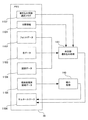
図1は、サムネール作成時のデータの流れを示した図である。ここで、メモリ30、縮小処理部140および余白部書き込み処理部141は、図2中に示したものと同一のブロックを指している。
【0142】
メモリ30上に格納された、現像処理済み画像データ1005はステップS602において、縮小処理部140によって縮小され、メモリ30上のサムネールデータ1006格納領域中の所定位置に格納されている。ステップS605において、余白部書き込み処理部141は、書き込み情報選択フラグ1107によって、画像データの付帯情報1101から余白部に書き込む情報を選択する。選択された付帯情報をもとに、余白部書き込み処理部141は、フォントデータ1102、色データ1103、図柄データ1104を組み合わせてサムネール余白部のデータを作成し、サムネールデータ1006格納領域中の所定位置に書き込む。
【0143】
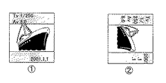
図10に、余白部分に付帯情報を書き込んだサムネールの例を示す。図中▲1▼例では、下側の余白部分に撮影日付を書き、上側の余白部分にシャッタースピードと絞り値を書いている。図中▲2▼の例では、画像付帯情報に、縦位置で撮影した情報が含まれていた場合に、文字を回転させて書き込んだ例を示している。
【0144】
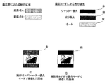
図11に、余白部分に付帯情報を書き込んだサムネールの別の例を示す。撮影者ごとに余白部の図柄を決めて選択し、また撮影時の撮影モードに対して色を設定しておくことにより、図中▲1▼の場合は撮影者Aがシャッター優先モードで撮影した画像、図中▲2▼の場合は撮影者Bが絞り優先モードで撮影した画像であることが、サムネールを見ることにより判別できる。これらは画像データとして書き込まれているので、サムネールを表示するアプリケーションソフトや、表示装置に依らず同様に表示される。
【0145】
以上、第1の実施例について説明した。
【0146】
(実施例2)
つぎに第2の実施例について説明する。
【0147】
本実施例における構成は第1の実施例と共通とし、説明は省略する。
【0148】
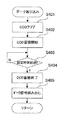
図12に、記録メディアに記録済みの画像データからサムネールを作成し、情報を書き込む処理のフローチャートを示す。まず記録部に記録されている圧縮済み画像データを読み出し(S701)、伸長処理を行い(S702)、メモリ30上に格納する(S703)。次に、メモリ30上に格納された画像データを読み出し、サムネールを作成する(S705)。このサムネール作成処理については、第1の実施例で説明したステップS137における処理と共通とし、説明を省略する。サムネール作成処理S705で作成されたサムネール画像を圧縮し(S706)、その結果得られた圧縮済みのサムネール画像と、記録部に記録されていた圧縮済み画像データを関連付けて画像ファイルを作成し(S707)、再度記録部に書き込みを行う(S708)。
【0149】
このような処理を行うことによって、記録部に記録されている画像データに対しても、情報付きサムネールを作成することが可能となる。
【0150】
なお、本実施例では、撮像機能を備えた画像処理装置を例に説明したが、撮像機能を持たない画像処理装置でも同様の処理を行うことは可能である。
【0151】
以上、第2の実施例について説明した。
【0152】
【発明の効果】
本願の請求項1に記載した発明によれば、画像表示装置や表示アプリケーションにかかわらず、画像データに付帯する情報を表示できるようにし、且つ画像データ自体に影響しないデータを得ることが可能となる。
【0153】
また、本願の請求項2に記載した発明によれば、画像データに付帯する情報を、数字または文字または絵文字により表現することが可能となる。
【0154】
また、本願の請求項3に記載した発明によれば、サムネールに付加する情報を使用者が選択することが可能となる。
【0155】
また、本願の請求項4に記載した発明によれば、数字または文字または絵文字の向きを変更してサムネールに付加することが可能となる。
【0156】
また、本願の請求項5に記載した発明によれば、画像に付帯する、画像の向きの情報に応じて、数字または文字または絵文字の向きを変更してサムネールに付加することが可能となる。
【0157】
また、本願の請求項6に記載した発明によれば、サムネールの余白部分の色または模様を変更することが可能となる。
【0158】
また、本願の請求項7に記載した発明によれば、サムネールの余白部分の色または模様により、画像データに付帯する情報を示すことが可能となる。
【0159】
また、本願の請求項8に記載した発明によれば、サムネールの余白部分の色または模様により示す情報を使用者が選択することが可能となる。
【0160】
また、本願の請求項9に記載した発明によれば、請求項1乃至8の発明により得られる効果をもち、且つ撮影する機能をもつ画像処理装置を提供することが可能となる。
【図面の簡単な説明】
【図1】本発明の実施例における、サムネール作成時のデータの流れを示した図である。
【図2】本発明の実施例の構成を示す図である。
【図3】本発明の実施例1の画像処理装置100の主ルーチンのフローチャートの一部である。
【図4】本発明の第1の実施例1の画像処理装置100の主ルーチンのフローチャートの一部である。
【図5】本発明の実施例1の画像処理装置100の測距・測光処理のフローチャートである。
【図6】本発明の実施例1の画像処理装置100のダーク取り込み処理のフローチャートである。
【図7】本発明の実施例の画像処理装置100の撮影処理のフローチャートである。
【図8】本発明の実施例1のサムネール作成処理のフローチャートである。
【図9】本発明の実施例における、サムネールのメモリ32上の占める領域を示した図である。
【図10】本発明の実施例において、サムネールの余白部分に付帯情報を書き込んだ状態を示した図である。
【図11】本発明の実施例において、サムネールの余白部分に付帯情報を書き込んだ状態を示した図である。
【図12】本発明の実施例2のサムネール作成処理のフローチャートである。
【符号の説明】
12 シャッター
14 撮像素子
16 A/D変換器
18 タイミング発生回路
20 画像処理回路
22 メモリ制御回路
26 D/A変換器
28 画像表示部
30 メモリ
32 画像圧縮・伸長回路
40 シャッター制御手段
42 測距手段
46 測光手段
48 フラッシュ
50 システム制御回路
52 メモリ
54 表示部
56 不揮発性メモリ
60 モードダイアルスイッチ
62 シャッタースイッチSW1
64 シャッタースイッチSW2
66 再生スイッチ
68 単写/連写スイッチ
70 操作部
72 電源スイッチ
80 電源制御手段
82 コネクタ
84 コネクタ
86 電源手段
90 インタフェース
92 コネクタ
94 インタフェース
96 コネクタ
98 記録媒体着脱検知手段
100 画像処理装置
104 光学ファインダー
106 レンズマウント
110 通信手段
112 コネクタ(またはアンテナ)
120 インタフェース
122 コネクタ
130 ミラー
132 ミラー
140 画像縮小処理回路
141 サムネール余白書き込み回路
142 縦位置検出手段
200 記録媒体
202 記録部
204 インタフェース
206 コネクタ
210 記録媒体
212 記録部
214 インタフェース
216 コネクタ
300 レンズユニット
306 レンズマウント
310 撮影レンズ
312 絞り
320 インタフェース
322 コネクタ
340 露光制御手段
342 測距制御手段
344 ズーム制御手段
350 レンズシステム制御回路[0001]
TECHNICAL FIELD OF THE INVENTION
The present invention relates to an image processing device and an image processing method.
[0002]
[Prior art]
2. Description of the Related Art Conventionally, there has been known a technology for managing information by attaching information to image data captured by a digital camera or the like. For example, there are Exif and DCF as standards set by the Japan Electronic Industry Development Association. In accordance with these standards, many display devices or application software for reading and displaying information attached to image data are commercially available. Further, a printing apparatus that prints an image related to an image to be printed in a margin portion at the time of image printing has been proposed (Japanese Patent Laid-Open No. 2000-036903).
[0003]
[Problems to be solved by the invention]
In these display devices or application software, there are various methods of displaying information attached to image data, and even when the same series of image data is used, different display devices and application software display different types of information, The user is often confused because the display layout is different. Also, in the case of display by printing, such a special function is required for the printing apparatus.
[0004]
The present invention has been made in order to solve the above-described problems, and has an image processing apparatus and an image processing method capable of creating image data capable of displaying supplementary information required by a user regardless of a display device or application software. It is intended to provide a processing method.
[0005]
[Means for Solving the Problems]
The image processing apparatus according to the present invention has a function of reducing image data and a function of reducing image data and adding a margin to create a thumbnail, and information related to the image data is provided in a margin of the thumbnail. Is added.
[0006]
BEST MODE FOR CARRYING OUT THE INVENTION
(Example 1)
Hereinafter, a first embodiment of the present invention will be described with reference to the drawings.
[0007]
FIG. 2 is a diagram showing the configuration of the embodiment of the present invention.
[0008]
In FIG. 2, reference numeral 100 denotes an image processing apparatus.
[0009]
Reference numeral 12 denotes a shutter for controlling the amount of exposure to the image sensor 14, and reference numeral 14 denotes an image sensor that converts an optical image into an electric signal.
[0010]
The light beam incident on the lens 310 is guided through the stop 312, the lens mounts 306 and 106, the mirror 130, and the shutter 12 by a single-lens reflex method, and can be formed on the image sensor 14 as an optical image.
[0011]
Reference numeral 16 denotes an A / D converter for converting an analog signal output of the image sensor 14 into a digital signal.
[0012]
Reference numeral 18 denotes a timing generation circuit that supplies a clock signal and a control signal to the image sensor 14, the A / D converter 16, and the D / A converter 26, and is controlled by the memory control circuit 22 and the system control circuit 50.
[0013]
Reference numeral 20 denotes an image processing circuit which performs predetermined pixel interpolation processing and color conversion processing on data from the A / D converter 16 or data from the memory control circuit 22.
[0014]
Further, in the image processing circuit 20, if necessary, predetermined arithmetic processing is performed using the captured image data, and based on the obtained arithmetic result, the system control circuit 50 causes the exposure control means 40, the distance measurement control means It is possible to perform TTL (through the lens) type AF (autofocus) processing, AE (automatic exposure) processing, and EF (flash light control) processing that control the image processing apparatus 42.
[0015]
Further, the image processing circuit 20 performs predetermined arithmetic processing using the captured image data, and also performs TTL AWB (auto white balance) processing based on the obtained arithmetic result.
[0016]
In the present embodiment, since the distance measuring means 42 and the light measuring means 46 are provided exclusively, the AF (auto focus) processing, the AE (automatic exposure) processing, the EF It is also possible to adopt a configuration in which each processing of (flash light control) processing is performed, and each processing of AF (auto focus) processing, AE (auto exposure) processing, and EF (flash light control) processing using the image processing circuit 20 is not performed. good.
[0017]
Alternatively, AF (auto focus) processing, AE (auto exposure) processing, and EF (flash light control) processing are performed using the distance measuring means 42 and the light measuring means 46, and the image processing circuit 20 is used. A configuration may be adopted in which each of AF (autofocus) processing, AE (auto exposure) processing, and EF (flash light control) processing is performed.
[0018]
Reference numeral 22 denotes a memory control circuit, which controls the A / D converter 16, the timing generation circuit 18, the image processing circuit 20, the D / A converter 26, the memory 30, and the compression / decompression circuit 32.
[0019]
The data of the A / D converter 16 is written to the memory 30 via the image processing circuit 20 and the memory control circuit 22, or the data of the A / D converter 16 is directly written to the memory 30 via the memory control circuit 22.
[0020]
Reference numeral 26 denotes a D / A converter, and 28 denotes an image display unit comprising a TFT LCD or the like. Display image data written in the memory 30 is displayed by the image display unit 28 via the D / A converter 26. .
[0021]
The electronic viewfinder function can be realized by sequentially displaying captured image data using the image display unit 28.
[0022]
The image display unit 28 can arbitrarily turn on / off the display in accordance with an instruction from the system control circuit 50. When the display is turned off, the power consumption of the image processing apparatus 100 can be significantly reduced. Can be done.
[0023]
Reference numeral 30 denotes a memory for storing a captured still image or moving image.
[0024]
Reference numeral 32 denotes a compression / decompression circuit for compressing / decompressing image data by adaptive discrete cosine transform (ADCT) or the like. The compression / decompression circuit 32 reads an image stored in the memory 30 and performs compression or decompression processing. Write to.
[0025]
Reference numeral 40 denotes a shutter control unit that controls the shutter 12 in cooperation with the aperture control unit 340 that controls the aperture 312 based on the photometric information from the photometric unit 46.
[0026]
Reference numeral 42 denotes a distance measuring unit for performing an AF (auto focus) process, which converts a light beam incident on the lens 310 into a stop 312, lens mounts 306 and 106, a mirror 130, and a distance measuring sub-mirror (not shown) by a single-lens reflex method. Through the distance measuring means 42, the in-focus state of an image formed as an optical image can be measured.
[0027]
Reference numeral 46 denotes a photometric unit for performing AE (automatic exposure) processing. The photometric unit 46 converts the light beam incident on the lens 310 into a stop 312, lens mounts 306 and 106, mirrors 130 and 132, and a not-shown The exposure state of the image formed as an optical image can be measured by inputting the light to the photometric unit 46 through the optical system.
[0028]
The light metering means 46 also has an EF (flash light control) processing function in cooperation with the flash 48.
[0029]
Reference numeral 48 denotes a flash, which also has a function of projecting AF auxiliary light and a function of flash light control.
[0030]
The system control circuit 50 controls the shutter control unit 40, the aperture control unit 340, and the distance measurement control unit 342 based on the calculation result obtained by calculating the image data captured by the image sensor 14 by the image processing circuit 20. Exposure control and AF (autofocus) control can also be performed using the video TTL method.
[0031]
Further, AF (autofocus) control may be performed using both the measurement result by the distance measuring unit 42 and the calculation result obtained by calculating the image data captured by the image sensor 14 by the image processing circuit 20.
[0032]
Then, the exposure control may be performed by using both the measurement result by the photometry unit 46 and the calculation result obtained by calculating the image data captured by the image sensor 14 by the image processing circuit 20.
[0033]
A system control circuit 50 controls the entire image processing apparatus 100, and a memory 52 stores constants, variables, programs, and the like for operation of the system control circuit 50.
[0034]
Reference numeral 54 denotes a display unit such as a liquid crystal display device or a speaker that displays an operation state or a message using characters, images, sounds, or the like in response to execution of a program in the system control circuit 50. It is installed at one or a plurality of locations in the vicinity of the part where it is easy to see, and is constituted by a combination of, for example, an LCD, an LED, a sound generating element, and the like.
[0035]
The display unit 54 has a part of its functions installed in the optical viewfinder 104.
[0036]
Among the display contents of the display unit 54, those displayed on the LCD or the like include, for example, a single shot / continuous shooting display, a self-timer display, a compression ratio display, a recording pixel number display, a recording number display, and a remaining number of images displayable. , Shutter speed display, Aperture value display, Exposure compensation display, Flash display, Red-eye reduction display, Macro shooting display, Buzzer setting display, Clock battery remaining display, Battery remaining display, Error display, Multi-digit information display Display of the attachment / detachment state of the recording media 200 and 210, attachment / detachment state display of the lens unit 300, communication I / F operation display, date / time display, display indicating the connection state with the external computer, and the like.
[0037]
In addition, among the display contents of the display unit 54, those displayed in the optical viewfinder 104 include, for example, an in-focus display, a shooting ready display, a camera shake warning display, a flash charging display, a flash charging completed display, a shutter speed display, There are an aperture value display, an exposure correction display, a recording medium writing operation display, and the like.
[0038]
Further, among the display contents of the display unit 54, those displayed on the LED or the like include, for example, an in-focus display, a shooting ready display, a camera shake warning display, a camera shake warning display, a flash charge display, a flash charge completion display, and a recording medium. There are a writing operation display, a macro shooting setting notification display, a secondary battery charge state display, and the like.
[0039]
Among the display contents of the display unit 54, the one displayed on a lamp or the like includes, for example, a self-timer notification lamp. This self-timer notification lamp may be used in common with the AF auxiliary light.
[0040]
Reference numeral 56 denotes an electrically erasable / recordable nonvolatile memory, for example, an EEPROM or the like.
[0041]
Reference numerals 60, 62, 64, 66, 68, and 70 denote operation means for inputting various operation instructions of the system control circuit 50, such as a switch, a dial, a touch panel, pointing by gaze detection, a single voice recognition device, or the like. It is composed of multiple combinations.
[0042]
Here, these operation means will be specifically described.
[0043]
Reference numeral 60 denotes a mode dial switch, which includes an automatic shooting mode, a program shooting mode, a shutter speed priority shooting mode, an aperture priority shooting mode, a manual shooting mode, a depth of focus priority (depth) shooting mode, a portrait shooting mode, a landscape shooting mode, and a close-up shooting mode. Each function photographing mode such as a mode, a sport photographing mode, a night scene photographing mode, a panoramic photographing mode and the like can be switched and set.
[0044]
Reference numeral 62 denotes a shutter switch SW1, which is turned on during the operation of a shutter button (not shown) to perform AF (auto focus) processing, AE (auto exposure) processing, AWB (auto white balance) processing, EF (flash light control) processing, and the like. Instruct operation start.
[0045]
Reference numeral 64 denotes a shutter switch SW2 which is turned on when the operation of a shutter button (not shown) is completed, and writes a signal read from the image sensor 12 into the memory 30 via the A / D converter 16 and the memory control circuit 22 in an exposure process. A development process using an operation in the image processing circuit 20 or the memory control circuit 22; a recording process in which image data is read from the memory 30, compressed by the compression / decompression circuit 32, and written into the recording medium 200 or 210. Instructs the start of a series of processing operations.
[0046]
Reference numeral 66 denotes a reproduction switch for instructing the start of a reproduction operation for reading a captured image from the memory 30 or the recording medium 200 or 210 and displaying the image on the image display unit 28 in the shooting mode.
[0047]
Reference numeral 68 denotes a single shooting / continuous shooting switch, which is a single shooting mode in which a single frame is shot when the shutter switch SW2 is pressed to be in a standby state, and a continuous shooting in which shooting is continuously performed while the shutter switch SW2 is pressed. Mode can be set.
[0048]
Reference numeral 70 denotes an operation unit including various buttons, a touch panel, and the like. A menu button, a set button, a macro button, a multi-screen playback page break button, a flash setting button, a single / continuous / self-timer switching button, and a menu shift + (plus) Button, menu move-(minus) button, playback image move + (plus) button, playback image-(minus) button, shooting image quality selection button, exposure compensation button, date / time setting button, panorama mode shooting and playback A selection / switch button for setting selection and switching of various functions at the time of execution, a decision / execution button for setting and execution of various functions at the time of shooting and playback of a panorama mode, etc., and ON of the image display unit 28 Image display ON / OFF switch for setting / OFF, image data shot immediately after shooting A quick review ON / OFF switch for setting a quick review function for automatic reproduction, a switch for selecting a compression ratio of JPEG compression, or a CCDRAW mode for digitizing a signal of an image pickup device as it is and recording it on a recording medium. The auto-focus operation starts when the shutter switch SW1 is pressed, and the focus is once focused once the playback switch that can set each function mode such as the compression mode switch, playback mode, multi-screen playback / deletion mode, and PC connection mode For example, there is an AF mode setting switch that can set a one-shot AF mode in which the in-focus state is maintained and a servo AF mode in which the auto-focus operation is continuously performed while the shutter switch SW1 is pressed.
[0049]
The functions of the plus button and the minus button are provided with a rotary dial switch, so that it is possible to more easily select a numerical value and a function.
[0050]
Reference numeral 72 denotes a power switch, which can switch and set the power-on and power-off modes of the image processing apparatus 100. Also, the power on and power off of various attached devices such as the lens unit 300, the external flash, and the recording media 200 and 210 connected to the image processing apparatus 100 can be switched and set.
[0051]
Reference numeral 80 denotes a power control unit, which includes a battery detection circuit, a DC-DC converter, a switch circuit for switching a block to be energized, and the like. The DC-DC converter is controlled based on an instruction from the system control circuit 50, and a required voltage is supplied to each unit including a recording medium for a required period.
[0052]
Reference numeral 82 denotes a connector, 84 denotes a connector, and 86 denotes a power supply means including a primary battery such as an alkaline battery or a lithium battery, a secondary battery such as a NiCd battery, a NiMH battery, or a Li battery, and an AC adapter.
[0053]
Reference numerals 90 and 94 denote an interface with a recording medium such as a memory card or a hard disk, reference numerals 92 and 96 denote connectors for connecting to a recording medium such as a memory card or a hard disk, and reference numeral 98 denotes a connector 92 or 96 to which a recording medium 200 or 210 is mounted. This is a recording medium attachment / detachment detecting means for detecting whether or not the recording medium is attached.
[0054]
In the present embodiment, the interface and the connector for attaching the recording medium are described as having two systems. Of course, the interface and the connector for attaching the recording medium may have a single or plural number of systems. Further, a configuration may be adopted in which interfaces and connectors of different standards are provided in combination.
[0055]
The interface and the connector may be configured using a card that conforms to a standard such as a PCMCIA card or a CF (Compact Flash (registered trademark)) card.
[0056]
Furthermore, when the interfaces 90 and 94 and the connectors 92 and 96 are configured by using a standard such as a PCMCIA card or a CF (Compact Flash (registered trademark)) card, a LAN card, a modem card, a USB card, an IEEE1394 Transfers image data and management information attached to the image data to and from other peripheral devices such as a computer and printer by connecting various communication cards such as a communication card such as a card, a P1284 card, a SCSI card, and a PHS. You can compete with each other.
[0057]
Reference numeral 104 denotes an optical finder, which guides a light beam incident on the lens 310 through a stop 312, lens mounts 306 and 106, and mirrors 130 and 132 by a single-lens reflex method, and can form and display an optical image. Thus, it is possible to perform photographing using only the optical viewfinder 104 without using the electronic viewfinder function of the image display unit 28. In the optical viewfinder 104, some functions of the display unit 54, for example, an in-focus display, a camera shake warning display, a flash charge display, a shutter speed display, an aperture value display, an exposure correction display, and the like are provided.
[0058]
A communication unit 110 has various communication functions such as RS232C, USB, IEEE1394, P1284, SCSI, modem, LAN, and wireless communication.
[0059]
Reference numeral 112 denotes a connector for connecting the image processing apparatus 100 to another device by the communication unit 110 or an antenna in the case of wireless communication.
[0060]
Reference numeral 120 denotes an interface for connecting the image processing apparatus 100 to the lens unit 300 in the lens mount 106, 122 denotes a connector for electrically connecting the image processing apparatus 100 to the lens unit 300, and 124 denotes the lens mount 106 and / or the connector. A lens attachment / detachment detecting unit that detects whether or not the lens unit 300 is attached to the lens unit 122.
[0061]
The connector 122 transmits a control signal, a status signal, a data signal, and the like between the image processing apparatus 100 and the lens unit 300, and has a function of supplying currents of various voltages. Further, the connector 122 may be configured to transmit not only electric communication but also optical communication, voice communication, and the like.
[0062]
Reference numerals 130 and 132 denote mirrors, which can guide light rays incident on the lens 310 to the optical viewfinder 104 by a single-lens reflex method. Note that the mirror 132 may have either a quick return mirror configuration or a half mirror configuration.
[0063]
Reference numeral 200 denotes a recording medium such as a memory card or a hard disk.
[0064]
The recording medium 200 includes a recording unit 202 including a semiconductor memory or a magnetic disk, an interface 204 with the image processing apparatus 100, and a connector 206 for connecting to the image processing apparatus 100.
[0065]
210 is a recording medium such as a memory card or a hard disk.
[0066]
The recording medium 210 includes a recording unit 212 including a semiconductor memory or a magnetic disk, an interface 214 with the image processing device 100, and a connector 216 for connecting to the image processing device 100.
[0067]
Reference numeral 300 denotes an interchangeable lens type lens unit.
[0068]
Reference numeral 306 denotes a lens mount that mechanically couples the lens unit 300 with the image processing apparatus 100. The lens mount 306 includes various functions for electrically connecting the lens unit 300 to the image processing apparatus 100.
[0069]
Reference numeral 310 denotes a photographing lens, and 312 denotes an aperture.
[0070]
Reference numeral 320 denotes an interface in the lens mount 306 for connecting the lens unit 300 to the image processing apparatus 100. Reference numeral 322 denotes a connector for electrically connecting the lens unit 300 to the image processing apparatus 100.
[0071]
The connector 322 transmits a control signal, a status signal, a data signal, and the like between the image processing apparatus 100 and the lens unit 300, and also has a function of supplying or supplying a current of various voltages. Further, the connector 322 may be configured to transmit not only electric communication but also optical communication, voice communication, and the like.
[0072]
Reference numeral 340 denotes an aperture control unit that controls the aperture 312 in cooperation with the shutter control unit 40 that controls the shutter 12 based on photometric information from the photometric unit 46.
[0073]
Reference numeral 342 denotes a distance measurement control unit that controls focusing of the photographing lens 310, and 344 denotes a zoom control unit that controls zooming of the photographing lens 310.
[0074]
Reference numeral 350 denotes a lens system control circuit that controls the entire lens unit 300. The lens system control circuit 350 includes a memory for storing operation constants, variables, programs, and the like, identification information such as a number unique to the lens unit 300, management information, function information such as an open aperture value and a minimum aperture value, and a focal length. It also has a function of a non-volatile memory for storing current and past set values.
[0075]
The operation of the image processing apparatus 100 will be described with reference to FIGS.
[0076]
FIG. 3 is a part of a flowchart of a main routine of the image processing apparatus 100 according to the embodiment of the present invention.
[0077]
When the power is turned on such as when the battery is replaced, the system control circuit 50 initializes flags, control variables, and the like, and performs predetermined initial settings necessary for each unit of the image processing apparatus 100 (S101).
[0078]
The system control circuit 50 determines the setting position of the power switch 66, and if the power switch 66 is set to the power OFF state (S102), changes the display of each display unit to an end state, and sets flags, control variables, and the like. The required parameters and setting values including the setting mode and the setting mode are recorded in the non-volatile memory 56, and the power supply control unit 80 executes predetermined termination processing such as shutting off unnecessary power supply of each unit of the image processing apparatus 100 including the image display unit 28. After performing (S103), the process returns to S102.
[0079]
If the power switch 66 has been set to power ON (S102), the system control circuit 50 causes the power control means 80 to determine whether the remaining capacity of the power source 86 composed of a battery or the like or the operating condition is in operation of the image processing apparatus 100. It is determined whether or not there is a problem (S104). If there is a problem, a predetermined warning display is performed using images and sounds using the display unit 54 (S105), and the process returns to S102.
[0080]
If there is no problem with the power supply 86 (S104), the system control circuit 50 determines the setting position of the mode dial 60, and if the mode dial 60 is set to the photographing mode (S106), the process proceeds to S108.
[0081]
If the mode dial 60 has been set to another mode (S106), the system control circuit 50 executes a process according to the selected mode (S107), and returns to S102 when the process is completed.
[0082]
The system control circuit 50 determines whether the recording medium 200 or 210 is mounted, obtains management information of image data recorded on the recording medium 200 or 210, and determines whether the operation state of the recording medium 200 or 210 is image processing. It is determined whether or not there is a problem in the operation of the apparatus 100, particularly, in the operation of recording and reproducing image data on the recording medium (S108). If there is a problem, a predetermined warning is displayed on the display unit 54 using an image or sound. After performing (S105), the process returns to S102.
[0083]
It is determined whether or not the recording medium 200 or 210 is mounted, the management information of the image data recorded on the recording medium 200 or 210 is obtained, and the operation state of the recording medium 200 or 210 indicates the operation of the image processing apparatus 100, particularly As a result of determining whether there is a problem in the recording / reproducing operation of the image data on the recording medium (S108), if there is no problem, the process proceeds to S109.
[0084]
The system control circuit 50 checks the setting state of the single shooting / continuous shooting switch 68 for setting single shooting / continuous shooting (S109), and if single shooting is selected, sets the single shooting / continuous shooting flag to single. If the continuous shooting is selected, the single / continuous shooting flag is set to continuous shooting (S111). If the flag setting is completed, the process proceeds to S112.
According to the single shooting / continuous shooting switch 68, when the shutter switch SW2 is pressed, a single frame is shot and a standby state is set, and when the shutter switch SW2 is pressed, shooting is continuously performed. The setting can be switched by arbitrarily switching the shooting mode.
[0085]
The state of the single / continuous shooting flag is stored in the internal memory of the system control circuit 50 or the memory 52.
[0086]
The system control circuit 50 uses the display unit 54 to display various setting states of the image processing apparatus 100 using images and sounds (S112). If the image display of the image display unit 28 is ON, various setting states of the image processing apparatus 100 are displayed by the image and the sound using the image display unit 28.
[0087]
Next, the photographer selects information to be added to the thumbnail to be created (S113). For example, information to be added to the thumbnail as an image can be selected from among many additional information such as date, shutter speed, aperture value, photographer ID, photographing mode, lens type to be used, and image size.
[0088]
If the shutter switch SW1 has not been pressed (S121), the process returns to S102.
[0089]
When the shutter switch SW1 is pressed (S121), the system control circuit 50 performs a distance measurement process to focus the photographing lens 10 on a subject, and performs a photometry process to determine an aperture value and a shutter time. Distance / photometry processing is performed (S122). In the photometry processing, the flash setting is also performed if necessary. The details of the distance measurement / photometry processing S122 will be described later with reference to FIG.
[0090]
The system control circuit 50 determines the state of the single / continuous shooting flag stored in the internal memory of the system control circuit 50 or the memory 52 (S123), and if single shooting has been set, the process proceeds to S125.
[0091]
As described above, when the single shooting is set in S123, the process proceeds to S125 without performing the dark capture process S124, thereby making it possible to reduce the release time lag when the shutter switch SW2 is pressed in S125. Become.
[0092]
If continuous shooting has been set (S123), a noise component such as a dark current of the image sensor 14 is accumulated with the shutter 12 closed for the same time as the main shooting, and a dark capture for reading out the noise image signal after the accumulation is completed. The process is performed (S124), and the process proceeds to S125.
[0093]
By performing a correction calculation process using the dark image data captured in the dark capture process, the captured image data is obtained with respect to image quality deterioration such as dark current noise generated by the image sensor 14 and pixel defects due to scratches inherent to the image sensor 14. Can be corrected.
[0094]
Details of the dark capture processing S124 will be described later with reference to FIG.
[0095]
If the shutter switch SW2 is not pressed (S125), the current process is repeated until the shutter switch SW1 is released (S126).
[0096]
If the shutter switch SW1 is released (S126), the process returns to S102.
[0097]
If the shutter switch SW2 is pressed (S125), the system control circuit 50 determines whether or not there is an image storage buffer area capable of storing captured image data in the memory 30 (S127). If there is no area in the buffer area where new image data can be stored, a predetermined warning display is performed by the display unit 54 using an image or sound (S128), and the process returns to S102.
[0098]
If there is an image storage buffer area capable of storing the captured image data in the memory 30 (S127), the system control circuit 50 reads out the image pickup signal that has been imaged and accumulated for a predetermined time from the image sensor 12, and performs A / D conversion. A photographing process for writing photographed image data in a predetermined area of the memory 30 is executed via the device 16, the image processing circuit 20, the memory control circuit 22, or directly from the A / D converter via the memory control circuit 22 ( S129).
[0099]
Details of the photographing process S129 will be described later with reference to FIG.
[0100]
When the photographing process S129 is completed, information to be attached to the image data is collected and written into the memory (S137). The information to be attached includes, for example, a shooting date and time, a shooting mode, a shutter speed, an aperture value, information on whether the image is a vertical position, an image quality, an image size, and the like.
[0101]
After the photographing process S129 is completed, the system control circuit 50 determines the state of the single / continuous shooting flag stored in the internal memory or the memory 52 of the system control circuit 50 (S130), and the continuous shooting is set. If so, the process proceeds to S132.
[0102]
The system control circuit 50 reads out a part of the image data written in a predetermined area of the memory 30 through the memory control circuit 22 and performs a WB (white balance) integration operation process, OB ( (Optical black) Integral calculation processing is performed, and the calculation result is stored in the internal memory of the system control circuit 50 or the memory 52.
[0103]
The system control circuit 50 reads out a part of the image data written in a predetermined area of the memory 30 through the memory control circuit 22 and performs a WB (white balance) integration operation process, OB ( (Optical black) Integral calculation processing is performed, and the calculation result is stored in the internal memory of the system control circuit 50 or the memory 52.
[0104]
Then, the system control circuit 50 uses the memory control circuit 22 and, if necessary, the image processing circuit 20 to read the captured image data written in a predetermined area of the memory 30 and read the captured image data into the internal memory or the memory of the system control circuit 50. Various development processes including AWB (auto white balance) process, gamma conversion process, and color conversion process are performed using the calculation results stored in the storage 52 (S132).
[0105]
Further, in the development process, a dark correction operation process for canceling dark current noise of the image sensor 14 and the like is performed by performing a subtraction process using dark image data captured in the dark capture process.
[0106]
Image data obtained as a result of performing the development processing S132 is written to a predetermined area of the memory 30. A thumbnail is created based on this data (S137).
[0107]
This thumbnail creation processing (S137) will be described later with reference to FIG.
[0108]
Then, the system control circuit 50 reads out the image data written in the predetermined area of the memory 30, and performs an image compression process according to the set mode by the compression / decompression circuit 32 (S 133). Image data that has been photographed and has undergone a series of image processing is written in the free image portion of the area. Also, the created thumbnail is compressed and written on the memory 30.
[0109]
A file is created by associating the compressed image data with the compressed thumbnail data (S140).
[0110]
With the execution of a series of photographing operations, the system control circuit 50 reads out the image data stored in the image storage buffer area of the memory 30 and sends the image data to a memory card or a compact flash (registered) via the interface 90 or 94 and the connector 92 or 96. A recording process for writing to the recording medium 200 or 210 such as a trademark card is started (S134).
[0111]
This recording start process is performed on the image data each time new image data is written in the empty image portion of the image storage buffer area of the memory 30 after the photographing and the series of processes are completed.
[0112]
Note that while the image data is being written to the recording medium 200 or 210, a recording medium writing operation display such as blinking of an LED is performed on the display unit 54 in order to clearly indicate that the writing operation is being performed.
[0113]
The system control circuit 50 determines whether the shutter switch SW1 has been pressed (S135).
[0114]
If the shutter switch SW1 has been released (S135), the process returns to S102.
[0115]
If the shutter switch SW1 has been pressed (S135), the state of the single / continuous shooting flag stored in the internal memory or the memory 52 of the system control circuit 50 is determined (S136), and the single shooting is set. If so, the process returns to S135, and the current process is repeated until SW1 is released.
[0116]
If continuous shooting has been set (S136), the process returns to S125 to perform continuous shooting, and the next shooting is performed.
[0117]
FIG. 5 shows a detailed flowchart of the distance measurement / photometry processing in S122 of FIG.
[0118]
In the distance measurement / photometry processing, various signals are exchanged between the system control circuit 50 and the aperture control means 340 or the distance measurement control means 342 through the interface 120, the connector 122, the connector 322, the interface 320, the lens control means. This is done via 350.
[0119]
The system control circuit 50 starts AF (autofocus) processing using the image sensor 14 distance measuring means 42 and distance measuring control means 342 (S201).
[0120]
The system control circuit 50 causes the light beam incident on the lens 310 to enter the distance measuring unit 42 via the stop 312, the lens mounts 306 and 106, the mirror 130, and a distance measuring sub-mirror (not shown), thereby forming an optical image. The in-focus state of the formed image is determined, and the distance measuring unit 42 is driven while driving the lens 310 using the distance measuring control unit 342 until the distance measurement (AF) is determined to be in focus (S203). The AF control for detecting the in-focus state is performed using the AF control (S202).
[0121]
If it is determined that the ranging (AF) is in focus (S203), the system control circuit 50 determines the focused ranging point from the plurality of ranging points in the shooting screen, and determines the determined ranging point. The distance measurement data and / or the set parameters together with the data are stored in the internal memory or the memory 52 of the system control circuit 50, and the process proceeds to S205.
[0122]
Subsequently, the system control circuit 50 starts AE (automatic exposure) processing using the photometric means 46 (S205).
[0123]
The system control circuit 50 causes the light beam incident on the lens 310 to enter the photometric unit 46 via the stop 312, the lens mounts 306 and 106, the mirrors 130 and 132, and a photometric lens (not shown), thereby forming an optical image. The exposure state of the formed image is measured, and photometric processing is performed using the exposure control means 40 (S206) until the exposure (AE) is determined to be appropriate (S206).
[0124]
If it is determined that the exposure (AE) is appropriate (S207), the system control circuit 50 stores the photometric data and / or setting parameters in the internal memory or the memory 52 of the system control circuit 50, and proceeds to S208.
[0125]
The system control circuit 50 determines an aperture value (Av value) and a shutter speed (Tv value) according to the exposure (AE) result detected in the photometry processing S206 and the shooting mode set by the mode dial 60. .
[0126]
Then, in accordance with the shutter speed (Tv value) determined here, the system control circuit 50 determines the charge accumulation time of the image sensor 14 and performs a shooting process.
[0127]
Based on the measurement data obtained in the photometric processing S206, the system control circuit 50 determines whether or not a flash is necessary (S208). If a flash is required, the system control circuit 50 sets a flash flag, and until the charging of the flash 48 is completed (S210). ), And charge the flash 48 (S209).
[0128]
When the charging of the flash 48 is completed (S210), the distance measurement / photometry processing routine S122 is ended.
[0129]
FIG. 6 shows a detailed flowchart of the dark capture process in S124 of FIG.
[0130]
After performing the charge clearing operation of the image sensor 14 (S401), the system control circuit 50 starts the charge accumulation of the image sensor 14 with the shutter 12 closed (S402).
[0131]
If the set predetermined charge accumulation time has elapsed (S403), the system control circuit 50 reads the charge signal from the image sensor 14 after terminating the charge accumulation of the image sensor 14 (S404), and executes the A / D converter. 16. The image data (dark image data) is written to a predetermined area of the memory 30 via the image processing circuit 20, the memory control circuit 22, or directly from the A / D converter 16 via the memory control circuit 22 (S405). ). The dark image data is held in a predetermined area of the memory 30 until a new distance measurement / photometry process is performed or the power of the image processing apparatus 100 is turned off.
When a series of processing is completed, the dark capture processing routine S124 ends. FIG. 7 shows a detailed flowchart of the photographing process in S129 of FIG.
[0132]
In the photographing process, various signals are exchanged between the system control circuit 50 and the aperture control unit 340 or the distance measurement control unit 342 via the interface 120, the connector 122, the connector 322, the interface 320, and the lens control unit 350. Done.
[0133]
The system control circuit 50 moves the mirror 130 to the mirror-up position by a mirror driving unit (not shown) (S301), and controls the aperture control unit 340 according to the photometric data stored in the internal memory or the memory 52 of the system control circuit 50. The aperture 312 is driven to a predetermined aperture value (S302).
[0134]
After performing the charge clearing operation of the image pickup device 14 (S303), the system control circuit 50 starts the charge accumulation of the image pickup device 14 (S304), and then opens the shutter 12 by the shutter control means 40 (S305). The exposure of the element 14 is started (S306).
[0135]
Here, it is determined whether or not the flash 48 is necessary based on the flash flag (S307). If necessary, the flash is fired (S308).
[0136]
The system control circuit 50 waits for the end of exposure of the image sensor 14 according to the photometric data (S309), closes the shutter 12 by the shutter control means 40 (S310), and ends the exposure of the image sensor 14.
[0137]
The system control circuit 50 drives the aperture 312 to the open aperture value by the aperture control means 340 (S311), and moves the mirror 130 to the mirror down position by the mirror driving means (not shown) (S312).
[0138]
If the set charge accumulation time has elapsed (S313), the system control circuit 50 reads the charge signal from the image sensor 14 after terminating the charge accumulation in the image sensor 14 (S314), and outputs the signal to the A / D converter 16, The captured image data is written to a predetermined area of the memory 30 via the image processing circuit 20 and the memory control circuit 22 or directly from the A / D converter 16 via the memory control circuit 22 (S315).
[0139]
FIG. 8 is a flowchart showing details of thumbnail creation. The developed image data created by the development process (S132) is read from the memory 32 through the memory control circuit 22 (S601), and reduced by the image data reduction circuit 140 for thumbnails (S602). At this time, the reduction ratio is selected to be smaller than the size of the thumbnail. The reduced data is stored in the memory 32 through the memory control circuit 22. Next, a blank area is secured at a predetermined position in the memory 32 through the memory control circuit 22 (S604). As the margin area, a margin generated when the aspect ratio of the image data and the aspect ratio of the thumbnail are different may be used. The additional information is written in the margin by the margin write processing circuit 141 (S605).
[0140]
FIG. 9 is a diagram showing a thumbnail area occupying the memory 32 after step S604 is completed. An area D1 in the figure is an area in which output data obtained as a result of reducing image data after development by the reduction circuit 140 is stored. The area D0 and the area D2 in the figure are the margin areas secured in step S604. In step S605, additional information is written to the areas D0 and D2.
[0141]
FIG. 1 is a diagram showing a flow of data when a thumbnail is created. Here, the memory 30, the reduction processing unit 140, and the margin writing processing unit 141 indicate the same blocks as those shown in FIG.
[0142]
The developed image data 1005 stored in the memory 30 is reduced by the reduction processing unit 140 in step S602, and is stored at a predetermined position in the thumbnail data 1006 storage area on the memory 30. In step S <b> 605, the margin write processing unit 141 selects information to be written in the margin from the supplementary information 1101 of the image data by the write information selection flag 1107. Based on the selected supplementary information, the margin write processing unit 141 creates data of the thumbnail margin by combining the font data 1102, the color data 1103, and the design data 1104, and stores the data in the thumbnail data 1006 storage area at a predetermined position. Write to.
[0143]
FIG. 10 shows an example of a thumbnail in which additional information is written in a margin. In the example (1) in the figure, the shooting date is written in the lower margin, and the shutter speed and aperture value are written in the upper margin. In the example of (2) in the figure, an example is shown in which the characters are rotated and written when the image accompanying information includes information captured in a vertical position.
[0144]
FIG. 11 shows another example of the thumbnail in which the supplementary information is written in the margin. By selecting and selecting the design of the margin for each photographer and setting the color for the photographing mode at the time of photographing, in the case of (1) in the figure, photographer A photographed in the shutter priority mode. In the case of the image, (2) in the figure, it can be determined by looking at the thumbnail that the photographer B has taken the image in the aperture priority mode. Since these are written as image data, they are displayed similarly regardless of application software for displaying thumbnails or display devices.
[0145]
The first embodiment has been described above.
[0146]
(Example 2)
Next, a second embodiment will be described.
[0147]
The configuration in this embodiment is common to that of the first embodiment, and the description is omitted.
[0148]
FIG. 12 shows a flowchart of a process of creating a thumbnail from image data recorded on a recording medium and writing information. First, the compressed image data recorded in the recording section is read (S701), decompressed (S702), and stored in the memory 30 (S703). Next, the image data stored in the memory 30 is read, and a thumbnail is created (S705). This thumbnail creation process is the same as the process in step S137 described in the first embodiment, and the description is omitted. The thumbnail image created in the thumbnail creation process S705 is compressed (S706), and an image file is created by associating the compressed thumbnail image obtained as a result with the compressed image data recorded in the recording unit (S707). ), Writing is performed again on the recording unit (S708).
[0149]
By performing such processing, it is possible to create a thumbnail with information even for image data recorded in the recording unit.
[0150]
In this embodiment, an image processing apparatus having an imaging function has been described as an example. However, the same processing can be performed by an image processing apparatus having no imaging function.
[0151]
The second embodiment has been described above.
[0152]
【The invention's effect】
According to the invention described in claim 1 of the present application, regardless of the image display device or the display application, it is possible to display information accompanying the image data and obtain data that does not affect the image data itself. .
[0153]
Further, according to the invention described in claim 2 of the present application, it is possible to express information attached to image data by numbers, characters, or pictograms.
[0154]
According to the invention described in claim 3 of the present application, the user can select information to be added to the thumbnail.
[0155]
Further, according to the invention described in claim 4 of the present application, it is possible to change the direction of a number, a character, or a pictogram and add it to a thumbnail.
[0156]
Further, according to the invention described in claim 5 of the present application, it is possible to change the direction of a number, a character, or a pictogram and add the thumbnail to a thumbnail according to information on the direction of the image attached to the image.
[0157]
Further, according to the invention described in claim 6 of the present application, it is possible to change the color or pattern of the margin portion of the thumbnail.
[0158]
Further, according to the invention described in claim 7 of the present application, it is possible to indicate information attached to image data by a color or a pattern of a margin portion of a thumbnail.
[0159]
Further, according to the invention described in claim 8 of the present application, it is possible for a user to select information indicated by a color or a pattern of a margin portion of a thumbnail.
[0160]
Further, according to the invention described in claim 9 of the present application, it is possible to provide an image processing apparatus having the effects obtained by the inventions of claims 1 to 8 and having a function of photographing.
[Brief description of the drawings]
FIG. 1 is a diagram showing a flow of data when a thumbnail is created in an embodiment of the present invention.
FIG. 2 is a diagram showing a configuration of an embodiment of the present invention.
FIG. 3 is a part of a flowchart of a main routine of the image processing apparatus 100 according to the first embodiment of the present invention.
FIG. 4 is a part of a flowchart of a main routine of the image processing apparatus 100 according to the first embodiment of the present invention.
FIG. 5 is a flowchart of a distance measurement / photometry process of the image processing apparatus 100 according to the first embodiment of the present invention.
FIG. 6 is a flowchart of dark capture processing of the image processing apparatus 100 according to the first embodiment of the present invention.
FIG. 7 is a flowchart of a shooting process of the image processing apparatus 100 according to the embodiment of the present invention.
FIG. 8 is a flowchart of a thumbnail creation process according to the first embodiment of the present invention.
FIG. 9 is a diagram showing an area occupied by a thumbnail on a memory 32 in the embodiment of the present invention.
FIG. 10 is a diagram showing a state in which additional information is written in a margin portion of a thumbnail in the embodiment of the present invention.
FIG. 11 is a diagram showing a state in which additional information is written in a margin portion of a thumbnail in the embodiment of the present invention.
FIG. 12 is a flowchart of a thumbnail creation process according to the second embodiment of the present invention.
[Explanation of symbols]
12 Shutter
14 Image sensor
16 A / D converter
18 Timing generation circuit
20 Image processing circuit
22 Memory control circuit
26 D / A converter
28 Image display section
30 memories
32 Image compression / decompression circuit
40 Shutter control means
42 Distance measuring means
46 Photometry
48 Flash
50 System control circuit
52 memory
54 Display
56 Non-volatile memory
60 mode dial switch
62 Shutter switch SW1
64 Shutter switch SW2
66 Playback switch
68 Single / Continuous switch
70 Operation unit
72 Power switch
80 Power control means
82 Connector
84 Connector
86 Power supply means
90 Interface
92 connector
94 Interface
96 connector
98 Recording medium attachment / detachment detection means
100 Image processing device
104 optical viewfinder
106 Lens mount
110 communication means
112 connector (or antenna)
120 interface
122 connector
130 mirror
132 mirror
140 Image reduction processing circuit
141 Thumbnail margin writing circuit
142 vertical position detecting means
200 recording medium
202 Recorder
204 interface
206 Connector
210 Recording medium
212 Recorder
214 interface
216 connector
300 lens unit
306 Lens mount
310 shooting lens
312 aperture
320 interface
322 connector
340 Exposure control means
342 Distance measurement control means
344 zoom control means
350 Lens system control circuit