JP2004149264A - Stacking device and circulation type banknote depositing and discharging machine - Google Patents
Stacking device and circulation type banknote depositing and discharging machine Download PDFInfo
- Publication number
- JP2004149264A JP2004149264A JP2002316642A JP2002316642A JP2004149264A JP 2004149264 A JP2004149264 A JP 2004149264A JP 2002316642 A JP2002316642 A JP 2002316642A JP 2002316642 A JP2002316642 A JP 2002316642A JP 2004149264 A JP2004149264 A JP 2004149264A
- Authority
- JP
- Japan
- Prior art keywords
- feeding
- banknote
- banknotes
- stacking
- stopper
- Prior art date
- Legal status (The legal status is an assumption and is not a legal conclusion. Google has not performed a legal analysis and makes no representation as to the accuracy of the status listed.)
- Granted
Links
Images


Classifications
-
- G—PHYSICS
- G07—CHECKING-DEVICES
- G07F—COIN-FREED OR LIKE APPARATUS
- G07F19/00—Complete banking systems; Coded card-freed arrangements adapted for dispensing or receiving monies or the like and posting such transactions to existing accounts, e.g. automatic teller machines
-
- B—PERFORMING OPERATIONS; TRANSPORTING
- B65—CONVEYING; PACKING; STORING; HANDLING THIN OR FILAMENTARY MATERIAL
- B65H—HANDLING THIN OR FILAMENTARY MATERIAL, e.g. SHEETS, WEBS, CABLES
- B65H83/00—Combinations of piling and depiling operations, e.g. performed simultaneously, of interest apart from the single operation of piling or depiling as such
- B65H83/02—Combinations of piling and depiling operations, e.g. performed simultaneously, of interest apart from the single operation of piling or depiling as such performed on the same pile or stack
- B65H83/025—Combinations of piling and depiling operations, e.g. performed simultaneously, of interest apart from the single operation of piling or depiling as such performed on the same pile or stack onto and from the same side of the pile or stack
-
- B—PERFORMING OPERATIONS; TRANSPORTING
- B65—CONVEYING; PACKING; STORING; HANDLING THIN OR FILAMENTARY MATERIAL
- B65H—HANDLING THIN OR FILAMENTARY MATERIAL, e.g. SHEETS, WEBS, CABLES
- B65H31/00—Pile receivers
- B65H31/04—Pile receivers with movable end support arranged to recede as pile accumulates
- B65H31/08—Pile receivers with movable end support arranged to recede as pile accumulates the articles being piled one above another
- B65H31/10—Pile receivers with movable end support arranged to recede as pile accumulates the articles being piled one above another and applied at the top of the pile
-
- B—PERFORMING OPERATIONS; TRANSPORTING
- B65—CONVEYING; PACKING; STORING; HANDLING THIN OR FILAMENTARY MATERIAL
- B65H—HANDLING THIN OR FILAMENTARY MATERIAL, e.g. SHEETS, WEBS, CABLES
- B65H31/00—Pile receivers
- B65H31/20—Pile receivers adjustable for different article sizes
-
- B—PERFORMING OPERATIONS; TRANSPORTING
- B65—CONVEYING; PACKING; STORING; HANDLING THIN OR FILAMENTARY MATERIAL
- B65H—HANDLING THIN OR FILAMENTARY MATERIAL, e.g. SHEETS, WEBS, CABLES
- B65H31/00—Pile receivers
- B65H31/26—Auxiliary devices for retaining articles in the pile
-
- B—PERFORMING OPERATIONS; TRANSPORTING
- B65—CONVEYING; PACKING; STORING; HANDLING THIN OR FILAMENTARY MATERIAL
- B65H—HANDLING THIN OR FILAMENTARY MATERIAL, e.g. SHEETS, WEBS, CABLES
- B65H31/00—Pile receivers
- B65H31/34—Apparatus for squaring-up piled articles
- B65H31/36—Auxiliary devices for contacting each article with a front stop as it is piled
-
- G—PHYSICS
- G07—CHECKING-DEVICES
- G07D—HANDLING OF COINS OR VALUABLE PAPERS, e.g. TESTING, SORTING BY DENOMINATIONS, COUNTING, DISPENSING, CHANGING OR DEPOSITING
- G07D11/00—Devices accepting coins; Devices accepting, dispensing, sorting or counting valuable papers
- G07D11/10—Mechanical details
- G07D11/16—Handling of valuable papers
-
- G—PHYSICS
- G07—CHECKING-DEVICES
- G07D—HANDLING OF COINS OR VALUABLE PAPERS, e.g. TESTING, SORTING BY DENOMINATIONS, COUNTING, DISPENSING, CHANGING OR DEPOSITING
- G07D11/00—Devices accepting coins; Devices accepting, dispensing, sorting or counting valuable papers
- G07D11/50—Sorting or counting valuable papers
-
- B—PERFORMING OPERATIONS; TRANSPORTING
- B65—CONVEYING; PACKING; STORING; HANDLING THIN OR FILAMENTARY MATERIAL
- B65H—HANDLING THIN OR FILAMENTARY MATERIAL, e.g. SHEETS, WEBS, CABLES
- B65H2301/00—Handling processes for sheets or webs
- B65H2301/40—Type of handling process
- B65H2301/42—Piling, depiling, handling piles
- B65H2301/422—Handling piles, sets or stacks of articles
- B65H2301/4223—Pressing piles
-
- B—PERFORMING OPERATIONS; TRANSPORTING
- B65—CONVEYING; PACKING; STORING; HANDLING THIN OR FILAMENTARY MATERIAL
- B65H—HANDLING THIN OR FILAMENTARY MATERIAL, e.g. SHEETS, WEBS, CABLES
- B65H2404/00—Parts for transporting or guiding the handled material
- B65H2404/10—Rollers
- B65H2404/11—Details of cross-section or profile
- B65H2404/111—Details of cross-section or profile shape
- B65H2404/1114—Paddle wheel
-
- B—PERFORMING OPERATIONS; TRANSPORTING
- B65—CONVEYING; PACKING; STORING; HANDLING THIN OR FILAMENTARY MATERIAL
- B65H—HANDLING THIN OR FILAMENTARY MATERIAL, e.g. SHEETS, WEBS, CABLES
- B65H2511/00—Dimensions; Position; Numbers; Identification; Occurrences
- B65H2511/10—Size; Dimensions
- B65H2511/11—Length
-
- B—PERFORMING OPERATIONS; TRANSPORTING
- B65—CONVEYING; PACKING; STORING; HANDLING THIN OR FILAMENTARY MATERIAL
- B65H—HANDLING THIN OR FILAMENTARY MATERIAL, e.g. SHEETS, WEBS, CABLES
- B65H2701/00—Handled material; Storage means
- B65H2701/10—Handled articles or webs
- B65H2701/19—Specific article or web
- B65H2701/1912—Banknotes, bills and cheques or the like
Abstract
Description
【0001】
【発明の属する技術分野】
本発明は、寸法差のある紙幣等の紙葉類を混合集積する集積装置、およびこの集積装置を用いた循環式紙幣入出金機に関する。
【0002】
【従来の技術】
例えば、紙幣入金機、紙幣入出金機、循環式紙幣入出金機、紙幣両替機、伝票処理機およびカード処理機等には、寸法差のある紙幣、伝票およびカード等の紙葉類(以下、紙幣、伝票およびカード等を紙葉類と呼ぶ)を混合集積する集積装置が用いられている。
【0003】
従来の集積装置(例えば、特許文献1参照)では、搬送路から1枚ずつ繰り込まれる紙葉類の繰込方向先端縁を可動先端係止部材で係止するとともに、この紙葉類の繰込方向後端縁を一定位置の後端規制壁で規制し、この紙葉類を集積台上に上下方向に集積する。集積台は紙葉類の集積量の増加に応じて下降する。可動先端係止部材は、集積台の上方域を紙葉類の繰込方向に対応した方向に移動可能とし、紙葉類の繰込方向長さに対応して後端規制壁との間隔を調整し、繰込方向の長さが異なる紙葉類をその繰込方向後端縁を基準として集積させている。紙葉類としては腰の強い段ボールシートを処理対象としている。また、集積台上に所定枚数の紙葉類が集積されれば、この紙葉類群を次行程に一括して送るようにしている。
【0004】
また、紙葉類として紙幣の入金および出金が可能で入金紙幣を出金紙幣に循環使用する循環式紙幣入出金機がある(例えば、特許文献2参照)。
【0005】
【特許文献1】
特開平4−350060号公報(第5頁ないし第6頁、図7)
【0006】
【特許文献2】
特開昭61−141091号公報(第1頁、第2図)
【0007】
【発明が解決しようとする課題】
しかしながら、従来の集積装置では、紙葉類として腰の強い段ボールシートを処理対象としており、仮に腰の弱い紙葉類、例えば紙幣、伝票、薄手の変形しやすいカード等の紙葉類を取り扱うとした場合、紙葉類の繰込方向先端側が繰込途中で垂れ下がり、可動先端係止部材と集積済み紙葉類の上面との間へ進入して停止し、その紙葉類の繰込方向後端縁が後端規制壁から離れた位置に集積され、集積ずれが生じる問題を有する。
【0008】
また、従来の集積装置では、集積台上に所定枚数の紙葉類が集積された場合、この紙葉類群を次行程に一括して送るようにしており、紙葉類の1枚ずつの繰り込みと1枚ずつの繰り出しとの両方を可能としたものではない。ところで、紙幣の場合、紙幣の1枚ずつの繰り込みと1枚ずつの繰り出しとの両方が可能で、紙幣を繰り込む繰込口を通じて紙幣を繰り出すことができる集積装置が望まれ、特に寸法差のある紙幣の繰り込みと繰り出しとの両方が可能な集積装置が望まれているが、従来の集積装置ではこのような機能を有せず、このような要望に対応できない問題を有する。
【0009】
本発明は、このような問題に鑑みなされたもので、寸法差を有する紙葉類をその繰込方向後端縁を基準として確実に集積できる集積装置を提供することを第1の目的とし、さらに、寸法差を有する異なる紙幣をその繰込方向後端縁を基準として確実に集積できるとともに1枚ずつ確実に繰り出すことができる集積装置および循環式紙幣入出金機を提供することを第2の目的とする。
【0010】
【課題を解決するための手段】
請求項1記載の集積装置は、寸法差を有する紙葉類を混合集積する集積装置であって、紙葉類を搬送する搬送路に設けられ、紙葉類の繰込方向長さに関連する情報を検知する繰込方向長さ関連情報検知部と、前記紙葉類を集積する集積空間部、この集積空間部に前記搬送路からの紙葉類を1枚ずつ繰り込む繰込手段、集積空間部に繰り込まれる紙葉類を上下方向に集積する集積台、この集積台を紙葉類繰込時に下降駆動する集積台駆動部、繰り込まれる紙葉類の繰込方向長さが最長の紙葉類の繰込方向先端縁を規制する先端規制壁、繰り込まれる紙葉類の繰込方向後端縁を規制する後端規制壁、これら先端規制壁と後端規制壁との間に上方から進出して繰り込まれる紙葉類の繰込方向長さが最長より短い紙葉類の繰込方向先端縁を係止する進出位置とこの進出位置から退避する退避位置との間で進退可能とする少なくとも1個のストッパ、このストッパを上下動可能に支持するとともに下降方向へ向けて付勢し進出位置に進出するストッパが集積済み紙葉類の繰込方向長さに応じて集積済み紙葉類の上面に当接してその上面を押圧しながら繰り込まれる紙葉類の繰込方向先端縁を係止する状態と集積済み紙葉類の繰込方向先端縁側に進出してその繰込方向先端縁を係止しながら繰り込まれる紙葉類の繰込方向先端縁を係止する状態とに切換可能とするストッパ支持手段、ストッパを進出位置と退避位置との間で進退駆動するストッパ駆動部を有する紙葉類集積部と、前記紙葉類繰込時に、前記集積済み紙葉類の上面位置が一定高さに位置するように前記集積台駆動部を制御するとともに、前記繰込方向長さ関連情報検知部による紙葉類の検知に基づき前記ストッパ駆動部を制御する制御部とを具備しているものである。
【0011】
そして、この構成では、先端規制壁と後端規制壁との間の進出位置に上方から進出して繰り込まれる紙葉類の繰込方向長さが最長より短い紙葉類の繰込方向先端縁を係止する少なくとも1個のストッパを上下動可能に支持するとともに下降方向へ向けて付勢したので、進出位置に進出したストッパが、集積済み紙葉類の繰込方向長さに応じて集積済み紙葉類の上面に当接してその上面を押圧しながら繰り込まれる紙葉類の繰込方向先端縁を係止する状態と集積済み紙葉類の繰込方向先端縁側に進出してその繰込方向先端縁を係止しながら繰り込まれる紙葉類の繰込方向先端縁を係止する状態とに切り換わるため、ストッパによって寸法差を有する紙葉類の繰込方向先端縁を確実に係止し、寸法差を有する紙葉類をその繰込方向後端縁を基準として確実に集積可能となる。
【0012】
請求項2記載の集積装置は、請求項1記載の集積装置において、紙葉類が紙幣であるものである。
【0013】
そして、この構成では、紙葉類が腰の弱い紙幣であっても確実に集積可能となる。
【0014】
請求項3記載の集積装置は、請求項1または2記載の集積装置において、繰込手段で繰り込まれる紙葉類の繰込方向先端縁を集積済み紙葉類の上面へガイドする揺動可能なガイド部材を備え、このガイド部材でガイドされて集積済み紙葉類の上面を移動する紙葉類の繰込方向先端縁をストッパおよび先端規制壁のいずれか一方で係止するものである。
【0015】
そして、この構成では、ガイド部材によって、紙葉類の繰込方向先端縁を集積済み紙葉類の上面へガイドし、集積済み紙葉類の上面を移動する紙葉類の腰を補強するため、繰り込まれる紙葉類が腰折れするのを防止し、紙葉類の繰込方向先端縁をストッパおよび先端規制壁のいずれか一方で確実に係止させて集積可能となる。
【0016】
請求項4記載の集積装置は、寸法差を有する紙幣を混合集積する集積装置であって、紙幣を搬送する搬送路に設けられ、紙幣の金種を識別する紙幣識別部と、前記紙幣を集積する集積空間部、この集積空間部に前記搬送路からの紙幣を1枚ずつ繰り込むとともに必要時に紙幣を1枚ずつ繰り出す繰込繰出手段、集積空間部に繰り込まれる紙幣を上下方向に集積する集積台、この集積台を昇降駆動する集積台駆動部、繰り込まれる紙幣の繰込方向長さが最長の紙幣の繰込方向先端縁を規制する先端規制壁、繰り込まれる紙幣の繰込方向後端縁を規制する後端規制壁、これら先端規制壁と後端規制壁との間に上方から進出して繰り込まれる紙幣の繰込方向長さが最長より短い紙幣の繰込方向先端縁を係止する進出位置とこの進出位置から退避する退避位置との間で進退可能とする少なくとも1個のストッパ、このストッパを上下動可能に支持するとともに下降方向へ向けて付勢し進出位置に進出するストッパが集積済み紙幣の繰込方向長さに応じて集積済み紙幣の上面に当接してその上面を押圧しながら繰り込まれる紙幣の繰込方向先端縁を係止する状態と集積済み紙幣の繰込方向先端縁側に進出してその繰込方向先端縁を係止しながら繰り込まれる紙幣の繰込方向先端縁を係止する状態とに切換可能とするストッパ支持手段、ストッパを進出位置と退避位置との間で進退駆動するストッパ駆動部を有する紙幣集積部と、前記搬送路に設けられ、前記紙幣識別部で識別された紙幣が紙幣集積部の近傍に到来したことを検知する紙幣到来検知部と、前記紙幣繰込時に、前記集積済み紙幣の上面位置が一定高さに位置するように前記集積台駆動部を制御するとともに、前記紙幣識別部による紙幣の識別および紙幣到来検知部による紙幣の検知に基づき前記ストッパ駆動部を制御する制御部とを具備しているものである。
【0017】
そして、この構成では、先端規制壁と後端規制壁との間の進出位置に上方から進出して繰り込まれる紙幣の繰込方向長さが最長より短い紙幣の繰込方向先端縁を係止する少なくとも1個のストッパを上下動可能に支持するとともに下降方向へ向けて付勢したので、進出位置に進出したストッパが、集積済み紙幣の繰込方向長さに応じて集積済み紙幣の上面に当接してその上面を押圧しながら繰り込まれる紙幣の繰込方向先端縁を係止する状態と集積済み紙幣の繰込方向先端縁側に進出してその繰込方向先端縁を係止しながら繰り込まれる紙幣の繰込方向先端縁を係止する状態とに切り換わるため、ストッパによって寸法差を有する紙幣の繰込方向先端縁を確実に係止し、寸法差を有する紙幣をその繰込方向後端縁を基準として確実に集積可能となる。さらに、寸法差を有する異なる紙幣をその繰込方向後端縁を基準として確実に集積可能となるために、集積された紙幣を1枚ずつ確実に繰り出すことも可能となる。
【0018】
請求項5記載の集積装置は、請求項4記載の集積装置において、ストッパの退避位置は、繰込時と繰出時とで同一位置とするとともに集積空間部外の先端規制壁の近傍位置とするものである。
【0019】
そして、この構成では、ストッパの退避位置を、繰込時と繰出時とで同一位置とするとともに集積空間部外の先端規制壁の近傍位置とするため、簡単かつ安価な構造になる。
【0020】
請求項6記載の集積装置は、請求項4記載の集積装置において、ストッパの退避位置は、繰込時と繰出時とで異なる二位置とするとともに繰出時における退避位置が繰込時における退避位置より大きく退避しかつ集積空間部外の位置とするものである。
【0021】
そして、この構成では、ストッパの退避位置を、繰込時と繰出時とで異なる二位置とするとともに繰出時における退避位置が繰込時における退避位置より大きく退避しかつ集積空間部外の位置とするため、紙幣繰込時にはストッパの進出および退避の移動が迅速になるとともに、紙幣繰出時には繰出動作にストッパが支障とならない。
【0022】
請求項7記載の集積装置は、請求項4ないし6いずれか記載の集積装置において、先端規制壁は、集積台上の紙幣を一括取出可能とする開放可能な扉を備えるものである。
【0023】
そして、この構成では、先端規制壁の扉を開放することによって集積台上に集積された紙幣を一括して迅速に取り出せる。
【0024】
請求項8記載の循環式紙幣入出金機は、紙幣の入金および出金が可能で入金紙幣を出金紙幣に循環使用する循環式紙幣入出金機であって、入金紙幣を一括して一時保留する一時保留部に請求項4ないし6いずれか記載の集積装置を備えるものである。
【0025】
そして、この構成では、入金紙幣を一括して一時保留する一時保留部に請求項4ないし6いずれか記載の集積装置を備えるため、寸法差のある紙幣の繰り込みによる一括一時保留および寸法差のある一時保留紙幣の繰り出しが確実になる。
【0026】
請求項9記載の循環式紙幣入出金機は、請求項8記載の循環式紙幣入出金機において、集積装置の先端規制壁に開放可能な扉を備え、入金承認時には一時保留紙幣を繰込繰出手段によって繰り出して収納するとともに、入金非承認時には扉の開放によって一時保留紙幣を一括取出可能とするものである。
【0027】
そして、この構成では、入金承認時には集積装置に集積された一時保留紙幣を繰込繰出手段によって1枚ずつ繰り出して収納し、入金非承認時には集積装置の先端規制壁の扉を開放することによって一時保留紙幣の返却を一括返却の形で迅速に可能となる。
【0028】
【発明の実施の形態】
以下、本発明の一実施の形態を図面を参照して説明する。
【0029】
図6に、紙葉類としての紙幣の入金および出金が可能で入金紙幣を出金紙幣に循環使用する循環式紙幣入出金機11を示す。この循環式紙幣入出金機11の機体12は、この循環式紙幣入出金機11を操作する操作面側を前面12aとし、操作面側と反対側つまり前面12aと反対側を後面12bとした場合、左右方向の横幅が狭く、前後方向の奥行きが長いとともに上下方向の高さが高い縦型に構成されている。機体12には、上部ユニット13および下部ユニット14が機体12の前面12a側からそれぞれ引出可能に設けられている。
【0030】
上部ユニット13の上面前側域には、前側から順に、紙幣を出金する紙幣出金口部21、および紙幣を入金する紙幣入金口部22が形成されている。これら紙幣出金口部21および紙幣入金口部22には、紙幣が立位姿勢でかつ長方形の紙幣の短手方向を上下方向として受入収納可能としている。紙幣出金口部21には、出金中に紙幣出金口部21を閉じるとともに出金終了時に開く透明シャッタ23が開閉可能に配置されているとともに、紙幣出金口部21内に紙幣を1枚ずつ繰り込む繰込手段24が配置されている。紙幣入金口部22には、紙幣入金口部22に投入された紙幣を機体12内へ1枚ずつ繰り出す繰出手段25が配置されている。
【0031】
上部ユニット13の前側域には、正規と識別された入金紙幣つまり入金正規紙幣を受収して金種混合状態で一括して一時保留する一時保留部26が配置されている。この一時保留部26の前面には閉鎖状態で図示しない電磁ロックによってロックされる透明な扉27が開閉可能に配置され、一時保留紙幣の返却時に電磁ロックが解除され、扉27に設けられている取手28を持って機体12の前面12aに開口されている図示しない前面開口部から前方へ開くことにより、一時保留部26内の入金非承認時の一時保留紙幣を一括取出可能としている。
【0032】
上部ユニット13内には、紙幣出金口部21、紙幣入金口部22および一時保留部26に接続されて紙幣を搬送する搬送路としての上部ユニット側紙幣搬送部29が配設されている。この上部ユニット側紙幣搬送部29は、紙幣出金口部21に紙幣を搬送する出金搬送路部30、紙幣入金口部22から繰り出される紙幣を搬送する入金搬送路部31、出金搬送路部30の途中に接続されて一時保留部26との間で紙幣を搬送する保留搬送路部32、後方から前方へ折り返す略U字形で上側の一端が入金搬送路部31に接続された識別搬送路部33、識別搬送路部33の上側の一端と下側の他端とを接続するバイパス搬送路部34、出金搬送路部30と識別搬送路部33の上側の一端(パイパス搬送路部34の上端)との間に接続された保留出金搬送路部35、保留出金搬送路部35に接続されて前方へ延設されたリジェクト紙幣搬送路部36、識別搬送路部33の下側の他端(パイパス搬送路部34の下端)に接続されて前方へ延設され前端がリジェクト紙幣搬送路部36に接続された収納出金搬送路部37を有している。少なくとも出金搬送路部30、保留搬送路部32、識別搬送路部33、保留出金搬送路部35および収納出金搬送路部37は、紙幣の搬送方向を正逆に反転させることができる。各搬送路部30〜37間の接続部分には紙幣の進行方向を切り換える切換部材38がそれぞれ配置されている。識別搬送路部33には搬送する紙幣の正偽や金種などを識別する繰込方向長さ関連情報検知部としての紙幣識別部39が配設されている。
【0033】
また、下部ユニット14には、機体12の前側域に、商品券などを収納する着脱ボックス41が着脱可能に配置されているとともに、リジェクト紙幣を収納するリジェクトボックス42が固定的に配置されている。さらに、リジェクトボックス42の後部域には、金種別に紙幣を収納する金種別紙幣収納部43が前後方向に並んで固定的に配置され、これら各金種別紙幣収納部43の上部に紙幣の受収および1枚ずつの繰り出しをする受収繰出手段44が配置され、金種別紙幣収納部43の上方域に各受収繰出手段44に接続して紙幣を搬送する下部ユニット側紙幣搬送部45が配置されている。なお、下部ユニット14の最後部には、必要に応じて金種別紙幣収納部43を増設可能とする増設スペース46が形成されている。
【0034】
リジェクトボックス42には、このリジェクトボックス42の上部から紙幣を1枚ずつ繰り込む繰込手段47が配置されている。
【0035】
各金種別紙幣収納部43には、集積台48が昇降可能に配置され、この集積台48上に紙幣の紙面を上下方向に向けて集積する。
【0036】
下部ユニット側紙幣搬送部45は、金種別紙幣収納部43の上方域に沿って前後方向に配置された主搬送路部49、この主搬送路部49から各金種別紙幣収納部43に繰り込む紙幣を搬送する繰込搬送路部50、各金種別紙幣収納部43から繰り出される紙幣を主搬送路部49に搬送する繰出搬送路部51を備え、各搬送路部49〜51の接続部分には紙幣の進行方向を切り換える切換部材52がそれぞれ配置されている。下部ユニット側紙幣搬送部45の主搬送路部49は、紙幣の搬送方向を正逆に反転させることができる。
【0037】
そして、金種別紙幣収納部43への紙幣繰込時には、集積台48上に紙幣を集積収納し、この紙幣の受収収納毎に紙幣の上面高さが高くなれば集積台48を順次下降させて紙幣を受け入れて集積収納する上面高さを一定の範囲内に保つようにする。また、金種別紙幣収納部43からの紙幣繰出時には、集積台48を上昇させ、受収繰出手段44によって集積台48上の紙幣を1枚ずつ繰り出す。
【0038】
また、機体12には、上部ユニット13と下部ユニット14との間において、機体12に収納した下部ユニット14の上面を閉塞状態に覆う板状の被覆部材61が固定されている。この被覆部材61には前端側に第1の開口部62および第2の開口部63がそれぞれ形成され、第1の開口部62には上部ユニット側紙幣搬送部29の収納出金搬送路部37の前端側と下部ユニット側紙幣搬送部45の前端側とを接続して紙幣を搬送する第1の接続通路部64が配置され、第2の開口部63には上部ユニット側紙幣搬送部29のリジェクト紙幣搬送路部36とリジェクトボックス42とを接続して紙幣を搬送する第2の接続通路部65がそれぞれ配置されている。これら第1の接続通路部64および第2の接続通路部65は、機体12側に固定された被覆部材61の第1の開口部62および第2の開口部63を通じて、機体12に対してそれぞれ引出可能とした上部ユニット13および下部ユニット14を機体12に収納した状態で接続されて上部ユニット13と下部ユニット14との間で紙幣の搬送が可能となる。さらに、第1の接続通路部64および第2の接続通路部65は、紙幣の搬送方向を正逆に反転させることができる。
【0039】
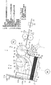
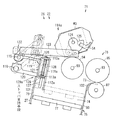
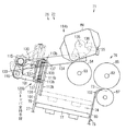
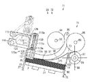
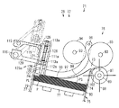
次に、図1ないし図4に、循環式紙幣入出金機11の一時保留部26に適用されて寸法差のある紙葉類としての紙幣Pを混合集積する集積装置71を示す。この集積装置71は、紙葉類集積部としての紙幣集積部72を有し、この紙幣集積部72の後部上端に設けられる繰込口部としての繰込繰出口部73を通じて、保留搬送路部32から紙幣集積部72に紙幣Pを1枚ずつ繰り込まれるとともに、紙幣集積部72から保留搬送路部32に紙幣Pを1枚ずつ繰り出せる。紙幣集積部72に対する紙幣Pの繰込方向および繰出方向は、紙幣Pの短手方向に設定されている。
【0040】
紙幣集積部72は、紙幣Pを集積する集積空間部74を有する集積枠部75、集積空間部74に保留搬送路部32からの紙幣Pを1枚ずつ繰り込むとともに必要時に紙幣Pを1枚ずつ繰り出す繰込手段としての繰込繰出手段76、集積空間部74に繰り込まれる紙幣Pを上下方向に集積する集積台77などを備えている。この紙幣集積部72は、両側に配置される上部ユニット13の側枠78a,78bによって支持されている。
【0041】
集積枠部75は、繰込繰出口部73を通じて保留搬送路部32に接続される上部側が後方へ例えば10度程度傾斜されており、集積台77上の集積空間部74に紙面を上下方向に向けた紙幣Pを後方へ傾斜した状態で上下方向に集積する。集積枠部75は外形が最大寸法の紙幣Pを収納可能とする長方形断面形状を有する筒状に形成され、繰り込まれる紙幣Pの繰込方向長さが最長の紙幣Pの繰込方向先端縁を規制する先端規制壁79、繰り込まれる紙幣Pの繰込方向後端縁を規制する後端規制壁80、および紙幣Pの長手方向の両端縁を規制する両端規制壁81を有している。先端規制壁79は、集積空間部74内の紙幣Pを一括して取り出すための扉27を別に有しているか、または扉27自体によって構成されている。
【0042】
繰込繰出手段76は、紙幣Pを載せて昇降する集積台77と連動して、保留搬送路部32から搬送されてくる紙幣Pを集積空間部74の集積台77上に繰り込むとともに、集積空間部74の集積台77上に集積されている紙幣Pを保留搬送路部32へ繰り出す。繰込繰出手段76は、繰込繰出口部73の上部で両側の側枠78a,78bに軸受82を介して回転自在に軸支された回転軸83を有し、この回転軸83には軸方向に複数のフィードローラ85およびガイドローラ86がそれぞれ取り付けられている。繰込繰出口部73の下側には各フィードローラ85に対向してその各フィードローラ85との間に紙幣Pを挟持して繰込搬送または繰出搬送する複数のゲートローラ87がそれぞれ取り付けられている。
【0043】
複数のゲートローラ87間には、各ガイドローラ86に対向して、例えばウレタン樹脂製で摩擦係数が比較的高いとともに弾性および柔軟性を有する複数の羽根88が周囲から突設された羽根ローラ89が配置されている。この羽根ローラ89は、紙幣繰込時にゲートローラ87間の側部位置である繰込位置に配置されて回転し、羽根88によって、紙幣Pの繰込方向先端縁を先端規制壁79へ向けて集積空間部74に繰り込むとともに、繰り込んだ紙幣Pの繰込方向後端縁を後端規制壁80に沿わせるように作用し、また、紙幣繰出時には、ゲートローラ87の側部位置から下方の待避位置に移動して待機する。
【0044】
ゲートローラ87の集積空間部74と反対の保留搬送路部32側には、フィードローラ85との間に紙幣Pを挟持して繰込搬送および繰出搬送する搬送ローラ90が配置されている。
【0045】
フィードローラ85の回転軸83には複数の軸受91によって複数のレバー92が揺動可能に軸支され、これらレバー92の先端側間に回転軸93が回転自在に軸支され、この回転軸93には軸方向に複数の繰出ローラ94が取り付けられている。レバー92は、繰出ローラ94の所定の下降位置で下方への揺動が規制され、図示しないスプリングによって繰出ローラ94が下降する方向へ向けて付勢されている。
【0046】
フィードローラ85の回転軸83は保留搬送路部32を含む上部ユニット側紙幣搬送部29とともにモータM2によって回転駆動され、フィードローラ85の回転軸83と繰出ローラ94の回転軸93とは例えばプーリ95aやベルトなどを用いた伝達機構95によって同一方向に連動して回転駆動される。回転軸83のフィードローラ85と回転軸93の繰出ローラ94とは同径であり、これらフィードローラ85と繰出ローラ94とは連動して同速で回転する。フィードローラ85および繰出ローラ94の周面には例えばゴムなどの摩擦係数が大きい摩擦面とこの摩擦面より摩擦係数が小さい滑り面とが周方向に交互に形成されており、紙幣繰出時にフィードローラ85および繰出ローラ94の摩擦面が集積台77上の紙幣Pに略同時に接触して繰り出しを開始するように構成されている。
【0047】
繰込繰出口部73の上方には支軸96が両側の側枠78a,78b間に取り付けられ、この支軸96の軸方向の複数箇所には、繰込繰出口部73から集積空間部74に繰り込まれる紙幣Pの繰込方向先端縁を集積台77上の集積済み紙幣Pの上面へガイドする複数のガイド部材97の一端がそれぞれ揺動可能に軸支されている。これら各ガイド部材97は、軽量な素材の薄板にて形成され、繰込繰出口部73から集積空間部74に繰り込まれる紙幣Pの繰込方向先端縁を集積台77上の集積済み紙幣Pの上面へガイドする湾曲部98、およびこの湾曲部98の先端側で集積積み紙幣Pの上面に接して押える略直線状の押え部99を有している。
【0048】
集積枠部75の先端規制壁79の上端には複数のガイド部材用切欠部100および複数のストッパ用切欠部101が形成されており、これらのうちのガイド部材用切欠部100に揺動するガイド部材97の先端部が進入可能になっている。後端規制壁80の上端には、ゲートローラ87と羽根ローラ89との間に位置して、繰込繰出口部73の下側に向けて湾曲形成されて紙幣Pの繰り込みおよび繰り出しを案内する複数の案内部102が形成されている。
【0049】
集積台77は、集積台駆動部としてのモータM1の駆動によって昇降する。
【0050】
なお、保留搬送路部32には、紙幣識別部39で識別された紙幣Pが紙幣集積部72の近傍に到来したことを検知する紙幣到来検知部としてのセンサS1、および紙幣Pを上下から挟持して搬送する搬送ローラ103が配置されている。また、レバー92の揺動角度を検知するセンサS2、およびガイド部材96の揺動角度を検知するセンサS3を備えている。
【0051】
また、紙幣集積部72は、集積空間部74外から選択的に集積空間部74内へ進出して繰り込まれる紙幣Pの繰込方向先端縁を係止して紙幣Pの繰込方向後端縁を後端規制壁80に揃えて繰込繰出手段76による繰出可能な一時保留位置に位置決めするストッパとしての複数の短幅用ストッパ111aおよび複数の中間幅用ストッパ111bをそれぞれ備えている。これらストッパ111a,111bによる紙幣Pの繰込方向先端縁の係止は、紙幣識別部39での金種識別による紙幣Pの短手方向の札幅と保留搬送路部32に配置されたセンサS1の検知とに基づいて選択的に実行する。すなわち、紙幣Pの金種をその短手方向の札幅が短幅の短幅紙幣PS、中間幅の中間幅紙幣PM、長幅の長幅紙幣PLのグループに分けて予め設定しておき、短幅紙幣PSの金種が紙幣識別部39で識別されるとともにセンサS1で検知されることにより、短幅用ストッパ111aが集積空間部74外から集積空間部74内へ進出し、繰り込まれてくる短幅紙幣PSの係止に待機し、同様に、中間幅紙幣PMの金種が紙幣識別部39で識別されるとともにセンサS1で検知されることにより、中間幅用ストッパ111bが集積空間部74外から集積空間部74内へ進出し、繰り込まれてくる中間幅紙幣PMの係止に待機する。また、長幅紙幣PLの金種が紙幣識別部39で識別されるとともにセンサS1で検知された場合には、両ストッパ111a,111bとも退避状態のままとされ、集積空間部74へ繰り込まれた長幅紙幣PLの繰込方向先端縁を先端規制壁79で係止する。なお、図2には、参考のためにストッパ111a,111bとも進出位置に進出した状態を示す。
【0052】
これらストッパ111a,111bは、紙幣Pの繰込方向先端縁を係止するストッパ面部112a,112b、およびこれらストッパ面部112a,112bの係止する面と反対側の面でその上端部および中間部から突設された取付片部113a,113bをそれぞれ有している。
【0053】
短幅用ストッパ111aおよび中間幅用ストッパ111b毎に、紙幣集積部72の先端規制壁79と後端規制壁80との間に上方から進出して繰り込まれる紙幣Pの繰込方向先端縁を係止する進出位置とこの進出位置から退避する退避位置との間で進退させる進退機構としての短幅用進退機構114aおよび中間幅用進退機構114bをそれぞれ備えている。
【0054】
先端規制壁79の外面に対向する位置でその先端規制壁79の外面と平行に上下の支軸115,116が並設され、これら支軸115,116の両端が両側の側枠78a,78bに軸受117,118によって回転自在に軸支されている。
【0055】
図2および図3に示すように、短幅用進退機構114aは、上側の支軸115に上側のリンク119の一端が固定され、下側の支軸116に下側のリンク120の一端が回転自在に軸支され、各リンク119,120の他端が支持部材121に回転自在に軸支され、この支持部材121に短幅用ストッパ111aが取り付けられている。すなわち、リンク119,120と支持部材121とで平行リンク構造が採られ、各支軸115,116を中心とする各リンク119,120の揺動により、支持部材121とともに短幅用ストッパ111aが図3に実線で示す進出位置と図3に2点差線で示す退避位置との間で平行移動しながら上下動する。この短幅用ストッパ111aの進出位置は、後端規制壁80との間の間隔が短幅紙幣PSの繰込方向の幅に対応した位置とし、また、短幅用ストッパ111aの退避位置は、繰込時と繰出時とで同一位置とするとともに集積空間部74外の先端規制壁79の近傍位置とする。
【0056】
一方の側枠78aの外側において、上側の支軸115の端部にはレバー122が取り付けられ、このレバー122の先端にリンク123の一端が回動可能に軸支されている。リンク123の他端位置に対応して、一方の側枠78aの内側にストッパ駆動部としてのモータM3が取り付けられる。このモータM3の駆動軸124には一方の側枠78aの外側にカム125が取り付けられ、このカム125にリンク123の他端が回動可能に軸支されている。カム125の両側域に配置されてこのカム125の回動位置を検知することで短幅用ストッパ111aの位置を検知するセンサS4が取り付けられている。センサS4は、短幅用ストッパ111aが退避位置より進出位置側に位置している状態でカム125によって遮光され、短幅用ストッパ111aが退避位置に位置している状態でカム125による遮光が解除されて透光状態となる。短幅用ストッパ111aの進出位置の検知は、モータM3の駆動により、退避位置の短幅用ストッパ111aが進出位置へ向けて移動を開始し、センサS4をカム125で遮光してからの経過時間を測定し、予め設定された設定時間経過時点で短幅用ストッパ111aが進出位置に到達したことを検知する。短幅用ストッパ111aの退避位置の検知は、センサS4がカム125による遮光が解除されて透光状態となったときで、カム125が図3の2点鎖線に位置したときである。
【0057】
短幅用ストッパ111aを取り付ける支持部材121には上下端に支持片部126が形成され、これら上下の支持片部126の各上面に短幅用ストッパ111aの上下の取付片部113aが配置され、これら支持片部126および取付片部113aを貫通して軸127が配置されている。軸127は、取付片部113aに固定され、支持片部126に対して上下方向にスライド可能としている。上側の支持片部126と下側の取付片部113aとの間には付勢手段としてのスプリング128が配置され、支持部材121に対して短幅用ストッパ111aを下方へ向けて付勢しているが、その付勢力は非常に弱く設定されている。そして、支持部材121、軸127およびスプリング128などによって、短幅用ストッパ111aを支持するストッパ支持手段129aが構成されている。すなわち、ストッパ支持手段129aでは、短幅用ストッパ111aを上下動可能に支持するとともに下降方向へ向けて付勢し、進出位置に進出する短幅用ストッパ111aが集積済み紙幣Pの繰込方向長さに応じて集積済み紙幣Pの上面に当接してその上面を押圧しながら繰り込まれる紙幣Pの繰込方向先端縁を係止する状態と、集積済み紙幣Pの繰込方向先端縁側に進出してその繰込方向先端縁を係止しながら繰り込まれる紙幣Pの繰込方向先端縁を係止する状態と、に選択的に切換可能としている。
【0058】
図2および図4に示すように、中間幅用進退機構114bは、上側の支軸115に上側のリンク130の一端が回転自在に軸支され、下側の支軸116に下側のリンク131の一端が固定され、各リンク130,131の他端が支持部材132に回転自在に軸支され、この支持部材132に中間幅用ストッパ111bが取り付けられている。すなわち、リンク130,131と支持部材132とで平行リンク構造が採られ、各支軸115,116を中心とする各リンク130,131の揺動により、支持部材132とともに中間幅用ストッパ111bが図4に実線で示す進出位置と図4に2点鎖線で示す退避位置との間で平行移動しながら上下動する。この中間幅用ストッパ111bの進出位置は、後端規制壁80との間の間隔が中間幅紙幣PMの繰込方向の幅に対応した位置とし、また、中間幅用ストッパ111bの退避位置は、繰込時と繰出時とで同一位置とするとともに集積空間部74外の先端規制壁79の近傍位置とする。
【0059】
他方の側枠78bの外側において、下側の支軸116の端部にはレバー133が取り付けられ、このレバー133の先端にリンク134の一端が回動可能に軸支されている。リンク134の他端位置に対応して、他方の側枠78bの内側にストッパ駆動部としてのモータM4が取り付けられ、このモータM4の駆動軸135には他方の側枠78bの外側にカム136が取り付けられ、このカム136にリンク134の他端が回動可能に軸支されている。カム136の両側域に配置されてこのカム136の回動位置を検知することで中間幅用ストッパ111bの位置を検知するセンサS5が取り付けられている。センサS5は、中間幅用ストッパ111bが退避位置以外に位置している状態でカム136によって遮光され、中間幅用ストッパ111bが退避位置に位置している状態でカム136による遮光が解除されて透光状態となる。中間幅用ストッパ111bの進出位置の検知は、モータM4の駆動により、退避位置の中間幅用ストッパ111bが進出位置へ向けて移動を開始し、センサS5をカム136で遮光してからの経過時間を測定し、予め設定された設定時間経過時点で中間幅用ストッパ111bが進出位置に到達したことを検知する。中間幅用ストッパ111bの退避位置の検知は、センサS5がカム136による遮光が解除されて透光状態となったときで、カム136が図4に2点鎖線に位置したときである。
【0060】
中間幅用ストッパ111bを取り付ける支持部材132には上下端に支持片部137が形成され、これら上下の支持片部137上に中間幅用ストッパ111bの上下の取付片部113bが配置され、これら支持片部137および取付片部113bを貫通して軸138が配置されている。軸138は、取付片部113bに固定され、支持片部137に対して上下方向にスライド可能としている。上側の支持片部137と下側の取付片部113bとの間には付勢手段としてのスプリング139が配置され、支持部材132に対して中間幅用ストッパ111bを下方へ向けて付勢しているが、その付勢力は非常に弱く設定されている。そして、支持部材132、軸138およびスプリング139などによって、中間幅用ストッパ111bを支持するストッパ支持手段129bが構成されている。すなわち、ストッパ支持手段129bでは、中間幅用ストッパ111bを上下動可能に支持するとともに下降方向へ向けて付勢し、進出位置に進出する中間幅用ストッパ111bが集積済み紙幣Pの繰込方向長さに応じて集積済み紙幣Pの上面に当接してその上面を押圧しながら繰り込まれる紙幣Pの繰込方向先端縁を係止する状態と、集積済み紙幣Pの繰込方向先端縁側に進出してその繰込方向先端縁を係止しながら繰り込まれる紙幣Pの繰込方向先端縁を係止する状態と、に選択的に切換可能としている。
【0061】
次に、図5に、集積装置71の制御系のブロック図を示す。集積装置71は制御部151を備え、この制御部151には、各センサS1〜S5を含むセンサ群Sx、紙幣識別部39、集積台77を昇降駆動するモータM1、繰込繰出手段76および保留搬送路部32を含む上部ユニット側紙幣搬送部29を正逆駆動するモータM2、短幅用ストッパ111aを進退駆動するモータM3、中間幅用ストッパ111bを進退駆動するモータM4が接続されている。
【0062】
制御部151は、紙幣繰込時に、集積済み紙幣Pの上面位置が一定の繰込高さに位置するようにモータM1を制御して集積台77を下降させる機能を有しているとともに、紙幣識別部39による紙幣Pの識別および紙幣到来検知部であるセンサS1による紙幣Pの検知に基づきモータM3,M4を制御してストッパ111a,111bを進退させる機能を有している。
【0063】
次に、本実施の形態の作用を説明する。
【0064】
まず、図6において、循環式紙幣入出金機11の入金処理動作および出金処理動作について説明する。
【0065】
入金処理時には、入金紙幣Pが立位姿勢で紙幣入金口部22に投入され、循環式紙幣入出金機11の上位端末で入金開始を操作することにより、入金処理を開始する。
【0066】
紙幣入金口部22に投入された入金紙幣Pは、紙幣入金口部22から上部ユニット側紙幣搬送部29の入金搬送路部31に1枚ずつ繰り出され、識別搬送路部33に搬送されて紙幣識別部39で識別される。
【0067】
紙幣識別部39で正規と識別された入金紙幣Pは、識別搬送路部33からバイパス搬送路部34、保留出金搬送路部35、出金搬送路部30および保留搬送路部32を通じて一時保留部26の集積空間部74に繰り込まれて一時保留される。一時保留部26の集積空間部74を開閉する前面の扉27は透明であるため、集積空間部74内での紙幣Pの集積状況を外部から視認できる。
【0068】
紙幣識別部39で識別不能と識別された入金紙幣Pつまり識別不能な紙幣Pは、識別搬送路部33からバイパス搬送路部34、保留出金搬送路部35および出金搬送路部30を通じて紙幣出金口部21に立位姿勢で繰り込まれ、入金紙幣の一時保留が終了した時点で透明シャッタ23が開放されて返却される。
【0069】
そして、紙幣入金口部22に投入された全ての入金紙幣Pの一時保留までの処理が完了したら、識別結果を表示し、入金承認または入金非承認を確認する。
【0070】
入金承認時には、一時保留部26に一時保留された一時保留紙幣Pの収納動作を開始する。一時保留部26の一時保留紙幣Pつまり収納紙幣Pは、一時保留部26から保留搬送路部32に1枚ずつ繰り出され、出金搬送路部30および保留出金搬送路部35を通じて識別搬送路部33に搬送されて紙幣識別部39で識別される。紙幣識別部39で正規と識別された収納紙幣Pは、収納出金搬送路部37から第1の接続通路部64を通じて下部ユニット側紙幣搬送部45の主搬送路部49に搬送され、この主搬送路部49から対応する金種の繰込搬送路部50を通じて対応する金種別紙幣収納部43に繰り込まれて集積収納される。
【0071】
入金非承認時には、一時保留部26の扉27をロックしていた電磁ロックが解除される。そのため、扉27の取手28を持って機体12の前方へ開き、一時保留部26の集積空間部74内の一時保留紙幣Pを一括して取り出し、扉27を閉じる。
【0072】
また、出金処理時には、出金の金種および枚数を含む金額など出金情報を循環式紙幣入出金機11の上位端末から入力し、出金開始を操作することにより、出金処理を開始する。
【0073】
1種類の紙幣Pを出金する場合には、該当する金種の金種別紙幣収納部43のみから1枚ずつ紙幣Pを順に繰り出し、また、複数金種の紙幣Pを出金する場合には、ある1つの金種の金種別紙幣収納部43から1枚ずつ紙幣Pを順に繰り出し、その繰り出しが完了したら次の金種の金種別紙幣収納部43から1枚ずつ紙幣Pを順に繰り出すというように、予め設定された金種順に紙幣Pを1枚ずつ繰り出す。
【0074】
金種別紙幣収納部43から繰り出される紙幣Pは、繰出搬送路部51および主搬送路部49から第1の接続通路部64を通じて上部ユニット側紙幣搬送部29の収納出金搬送路部37および識別搬送路部33に搬送されて紙幣識別部39で識別される。
【0075】
紙幣識別部39で正規と識別された紙幣Pは、識別搬送路部33から保留出金搬送路部35および出金搬送路部30を通じて紙幣出金口部21に繰り込まれて立位姿勢で集積される。
【0076】
紙幣識別部39で識別不能と判断された紙幣Pは、識別搬送路部33から保留出金搬送路部35、リジェクト紙幣搬送路部36から第2の接続通路部65を通じて下部ユニット14のリジェクトボックス42に繰り込まれて収納される。
【0077】
出金額に対応した出金紙幣Pが紙幣出金口部21に繰り込まれて集積されたら、透明シャッタ23が開放される。紙幣出金口部21から出金紙幣Pが取り出されたら透明シャッタ23を閉じる。
【0078】
次に、循環式紙幣入出金機11の一時保留部26を構成する集積装置71の動作について説明する。
【0079】
集積装置71の集積空間部74に紙幣Pを繰り込んで集積させる場合には、羽根ローラ89がゲートローラ87間の側部位置である繰込位置に移動する。ストッパ111a,111bは、いずれも退避位置で待機し、紙幣識別部39での識別およびセンサS1での検知に応じて選択的に退避位置から進出位置に進退されることになる。
【0080】
そして、紙幣集積時つまり入金紙幣一時保留時において、紙幣識別部39で識別されてセンサS1で検知される紙幣Pが短幅紙幣PSの金種の場合には、モータM3の駆動によって短幅用ストッパ111aが退避位置から進出位置に進出する。
【0081】
このとき、図7に示すように、集積空間部74内で集積台77上に集積された集積済み紙幣Pのうち上部域に短幅紙幣PSが多く集積された状態の場合には、集積済みの短幅紙幣PSの繰込方向先端縁側に短幅用ストッパ111aの下部が進入し、その集積済みの短幅紙幣PSの繰込方向先端縁を係止しながら繰り込まれてくる予定の短幅紙幣PSの係止に備える。
【0082】
図8または図1に示すように、集積空間部74内で集積台77上に集積された集積済み紙幣Pの上部域に中間幅紙幣PMまたは長幅紙幣PLが多く集積された状態の場合には、短幅用ストッパ111aが進出位置に移動する途中で短幅用ストッパ111aの下端が中間幅紙幣PMまたは長幅紙幣PLの上面に当接する。例えば、図8に示すように、集積済みの中間幅紙幣PMの上面に載る短幅用ストッパ111aが支持部材121に対してスプリング128の付勢に抗して上昇する。そのため、集積済みの中間幅紙幣PMまたは長幅紙幣PLの上面を短幅用ストッパ111aが押圧しながら、繰り込まれてくる予定の短幅紙幣PSの係止に備える。
【0083】
図9に示すように、集積空間部74内で集積台77上に集積された集積済み紙幣Pのうち上部域に短幅紙幣PSが多く集積されるとともにこれら短幅紙幣PSに混在して中間幅紙幣PM(または長幅紙幣PL)が1枚または数枚集積された状態の場合には、集積済みの短幅紙幣PSの繰込方向先端縁側に短幅用ストッパ111aの下部が進入し、短幅紙幣PSに混在した中間幅紙幣PM(または長幅紙幣PL)の繰込方向後端縁は短幅用ストッパ111aで下方へ押し曲げられた状態となり、この状態で繰り込まれてくる予定の短幅紙幣PSの係止に備える。このとき、短幅用ストッパ111aを下方へ付勢するスプリング128の付勢力は弱いため、短幅用ストッパ111aが上昇することで中間幅紙幣PM(または長幅紙幣PL)の繰込方向後端縁の押し曲がりが戻る。なお、中間幅紙幣PM(または長幅紙幣PL)の繰込方向後端縁は短幅用ストッパ111aで下方へ押し曲げられるが、中間幅紙幣PM(または長幅紙幣PL)の繰込時に、ゲートローラ87の側部に配置されている羽根ローラ89の羽根88の作用によって中間幅紙幣PM(または長幅紙幣PL)の繰込方向後端縁を後端規制壁80に沿わせているため、および集積枠部75が後端規制壁80側に下降傾斜していて中間幅紙幣PM(または長幅紙幣PL)の繰込方向後端縁を後端規制壁80に沿わせる作用を有するため、中間幅紙幣PM(または長幅紙幣PL)の繰込方向後端縁が後端規制壁80から大きく離れることはない。
【0084】
このように集積済み紙幣Pが短幅紙幣PSか、中間幅紙幣PMか、長幅紙幣PLかなどに応じて、短幅用ストッパ111aの進出位置での状態が異なる。なお、集積済み紙幣Pの上面にはガイド部材97が載り、集積済み紙幣Pを集積台77上に押え付けている。
【0085】
また、紙幣識別部39で識別されてセンサS1で検知される紙幣Pが中間幅紙幣PMの金種の場合には、モータM4の駆動によって中間幅用ストッパ111bが退避位置から進出位置に進出する。
【0086】
このとき、図10に示すように、集積空間部74内で集積台77上に集積された集積済み紙幣Pのうち上部域に中間幅紙幣PM(または短幅紙幣PS)が多く集積された状態の場合には、集積済みの中間紙幣PM(または短幅紙幣PS)の繰込方向先端縁側に中間幅用ストッパ111bの下部が進入し、集積済みの中間紙幣PM(または短幅紙幣PS)の繰込方向先端縁を係止しながら繰り込まれてくる予定の中間幅紙幣PMの係止に備える。
【0087】
図1に示すように、集積空間部74内で集積台77上に集積された集積済み紙幣Pの上部域に長幅紙幣PLが多く集積された状態の場合には、中間幅用ストッパ111bが進出位置に移動する途中で中間幅用ストッパ111bの下端が長幅紙幣PLの上面に当接する。集積済みの長幅紙幣PLの上面に載る中間幅用ストッパ111bが支持部材132に対してスプリング139の付勢に抗して上昇する。そのため、集積済みの長幅紙幣PLの上面を中間幅用ストッパ111bで押圧しながら、繰り込まれてくる予定の中間幅紙幣PMの係止に備える。なお、スプリング139もスプリング128と同様に不勢力は弱い。
【0088】
このように集積済み紙幣Pが短幅紙幣PSか、中間幅紙幣PMか、長幅紙幣PLかなどに応じて、中間幅用ストッパ111bの進出位置での状態が異なる。なお、集積済み紙幣Pの上面にはガイド部材97が載り、集積済み紙幣Pを集積台77上に押え付けている。
【0089】
また、紙幣識別部39で識別されてセンサS1で検知される紙幣Pが長幅紙幣PLの金種の場合には、図11に示すように、モータM3,M4とも駆動されず、短幅用ストッパ111aおよび中間幅用ストッパ111bとも退避位置に保たれ、先端規制壁79での繰り込まれてくる予定の長幅紙幣PLの係止に備える。
【0090】
そして、図7ないし図9に示すように、紙幣識別部39で識別されてセンサS1で検知された短幅紙幣PSが保留搬送路部32から送り込まれてきた場合、この短幅紙幣PSは、フィードローラ85とゲートローラ87との間に挟持されて繰込繰出口部73から集積空間部74に繰り込まれ、短幅紙幣PSの繰込方向先端縁がガイド部材97によって集積済み紙幣Pの上面へガイドされ、短幅紙幣PSの繰込方向先端縁が集積済み紙幣Pの上面を移動して短幅用ストッパ111aに当接して係止され、短幅紙幣PSの繰込方向後端縁が後端規制壁80に沿う位置を基準とする集積位置つまり一時保留位置に位置決めされて集積される。ゲートローラ87の側部に配置されている羽根ローラ89の羽根88の回転によって、短幅紙幣PSの繰込方向先端縁を先端規制壁79へ向けて集積空間部74に繰り込むとともに、繰り込んだ短幅紙幣PSの繰込方向後端縁を後端規制壁80に沿わせるように作用する。
【0091】
このとき、図7および図9に示すように、短幅用ストッパ111aは、集積済みの短幅紙幣PSの繰込方向先端縁を係止しながら繰り込まれる短幅紙幣PSの繰込方向先端縁を係止しているか、図8および図1に示すように、集積済みの中間幅紙幣PMまたは長幅紙幣PLの上面を押圧しながら繰り込まれる短幅紙幣PSの繰込方向先端縁を係止しているため、短幅紙幣PSの繰込方向先端縁が短幅用ストッパ111aの下側に入り込むことなく、短幅紙幣PSを確実に係止できる。
【0092】
さらに、ガイド部材97によって、短幅紙幣PSの繰込方向先端縁の集積済み紙幣Pの上面へのガイドと集積済み紙幣Pの上面に沿った送りガイドとをするため、短幅紙幣PSの腰を補強し、繰り込まれる短幅紙幣PSが腰折れするのを防止し、この腰を補強される短幅紙幣PSの繰込方向先端縁を短幅用ストッパ111aで確実に係止させて集積できる。
【0093】
短幅用ストッパ111aは短幅紙幣PSの係止後、直ちに集積空間部74外の退避位置へ退避し、次の紙幣Pの集積空間部74への繰り込みに待機する。
【0094】
紙幣繰込に伴ってその紙幣の厚み分だけガイド部材97が押し上げられ、このガイド部材97の揺動角度をセンサS3で監視し、集積台77上に集積された紙幣Pの上面高さが高くなってセンサS3で検知される揺動角度が所定値に達する毎に、集積台77を順次下降させて紙幣Pを受け入れて集積する上面高さを一定の範囲内に保つようにする。
【0095】
また、図10に示すように、紙幣識別部39で識別されてセンサS1で検知された中間幅紙幣PMが保留搬送路部32から送り込まれてきた場合にも、上述した短幅紙幣PSと同様の動作を有するものであり、ガイド部材97によって中間幅紙幣PMの繰込方向先端縁の集積済み紙幣Pの上面へのガイドと集積済み紙幣Pの上面に沿った送りガイドとを行い、この中間幅紙幣PMの繰込方向先端縁が進出位置に進出した中間幅用ストッパ111bで係止され、中間幅紙幣PMの繰込方向後端縁が後端規制壁80に沿う位置を基準として集積される。なお、中間幅ストッパ111bは中間幅紙幣PMの係止後、直ちに集積空間部74外の退避位置へ待機し、次の紙幣Pの集積空間部74への繰り込みに待機する。
【0096】
また、図11に示すように、紙幣識別部39で識別されてセンサS1で検知された長幅紙幣PLが保留搬送路部32から送り込まれてきた場合、この長幅紙幣PLは、上述した短幅紙幣PSおよび中間幅紙幣PMと同様にガイド部材97でガイドされながら集積空間部74に繰り込まれ、長幅紙幣PLの繰込方向先端縁が先端規制壁79に当接して係止され、長幅紙幣PLの繰込方向後端縁が後端規制壁80に沿う位置を基準として集積される。
【0097】
このように、紙幣繰込時には、紙幣識別部39での金種識別に応じてストッパ111a,111bが選択的に進出し、繰り込まれる紙幣Pの繰込方向先端縁をストッパ111a,111bまたは先端規制壁79で規制し、紙幣Pの繰込方向後端縁を後端規制壁80に沿わせた集積位置に確実に集積させることができる。
【0098】
次に、集積装置71の集積空間部74に集積した紙幣Pを繰り出す場合には、羽根ローラ89がゲートローラ87間の側部位置である繰込位置から退避する退避位置に移動させる。
【0099】
集積台77を上昇させてこの集積台77上の紙幣Pの上面を所定の繰出高さまで上昇させる。すなわち、集積台77を上昇させ、紙幣Pの上面を繰出ローラ94に当接させるとともに、レバー92を揺動させて繰出ローラ94を上方へ押し上げ、センサS2でレバー92の揺動角度が所定角度になったことを検知したら、集積台77の上昇を停止させる。集積台77上の紙幣Pの上面を所定の繰出高さまで上昇させることで、紙幣Pの上面はフィードローラ85にも当接する。
【0100】
フィードローラ85および繰出ローラ94の回転により、フィードローラ85および繰出ローラ94の周面の一部に設けられている摩擦面が集積台77上の紙幣Pに略同時に接触し、それら摩擦面が接触した最上層の1枚の紙幣Pを繰込繰出口部73へ繰り出し、フィードローラ85とゲートローラ87との間に挟持して保留搬送路部32へ送り出す。
【0101】
センサS2でレバー92の揺動角度を監視し、紙幣繰出に伴って集積台77上の紙幣Pの高さが低くなれば、集積台77を上昇させ、集積台77上の紙幣Pの上面の繰出高さを一定に保つようにする。
【0102】
したがって、集積装置71によれば、先端規制壁79と後端規制壁80との間の進出位置に上方から進出して繰り込まれる紙幣Pの繰込方向長さが最長の長幅紙幣PLより短い短幅紙幣PS、中間幅紙幣PMの繰込方向先端縁を係止するストッパ111a,111bを上下動可能に支持するとともに下降方向へ向けて付勢したので、進出位置に進出したストッパ111a,111bが、集積済み紙幣Pの繰込方向長さに応じて、集積済み紙幣Pの上面に当接してその上面を押圧しながら繰り込まれる短幅紙幣PSまたは中間幅紙幣PMの繰込方向先端縁を係止する状態と、集積済み紙幣Pの繰込方向先端縁側に進出してその繰込方向先端縁を係止しながら繰り込まれる短幅紙幣PSまたは中間幅紙幣PMの繰込方向先端縁を係止する状態と、に切り換わるため、ストッパ111a,111bによって寸法差を有する紙幣Pの繰込方向先端縁を確実に係止でき、寸法差を有する紙幣Pをその繰込方向後端縁を基準として確実に集積できる。さらに、寸法差を有する異なる紙幣Pをその繰込方向後端縁を基準として確実に集積できるために、集積された紙幣を1枚ずつ確実に繰り出すことができる。
【0103】
ガイド部材97によって、紙幣Pの繰込方向先端縁を集積済み紙幣Pの上面へガイドし、集積済み紙幣Pの上面を移動する紙幣Pの腰を補強するため、繰り込まれる紙幣Pが腰折れするのを防止し、紙幣Pの繰込方向先端縁をストッパ111a,111bおよび先端規制壁79のいずれか一方で確実に係止させて集積できる。
【0104】
ストッパ111a,111bの退避位置は、繰込時と繰出時とで同一位置であるとともに集積空間部74外の先端規制壁79の近傍位置であるため、簡単かつ安価な構造にできる。
【0105】
なお、国によっては、処理する全金種について、各紙幣Pのそれぞれに短手方向の長短差がある場合があり、短幅紙幣PS、中間幅紙幣PM、長幅紙幣PLのなかでも多少の寸法差がある場合があるが、紙幣繰込時には、羽根ローラ89の羽根88の作用によって紙幣Pの繰込方向後端縁を後端規制壁80に沿わせる作用を有するとともに、集積枠部75が後端規制壁80側に下降傾斜していて紙幣Pの繰込方向後端縁を後端規制壁80に沿わせる作用を有するため、紙幣Pの繰込方向後端縁を後端規制壁80に沿わせて位置決め集積できる。そして、紙幣繰出時には、フィードローラ85および繰出ローラ94の周面の一部に設けられている摩擦面が紙幣Pに略同時に接触して繰り出しが開始されるが、上述の紙幣Pの長さの多少の寸法差は繰出開始時の誤差の範囲内に相当し、紙幣Pを正常に繰り出すことができる。
【0106】
なお、ストッパ111a,111bの退避位置は、繰込時と繰出時とで異なる二位置とするとともに繰出時における退避位置が繰込時における退避位置より大きく退避しかつ集積空間部74外の位置とすることにより、紙幣繰込時にはストッパ111a,111bの進出および退避の移動を迅速にできるとともに、紙幣繰出時には繰出動作にストッパ111a,111bが支障とならないようにできる。
【0107】
また、循環式紙幣入出金機11に集積装置71を備えるため、寸法差のある紙幣Pの繰り込みによる一括一時保留および寸法差のある一時保留紙幣Pの繰り出しが確実にできる。しかも、入金承認時には集積装置71に集積された一時保留紙幣Pを繰込繰出手段76によって1枚ずつ繰り出して収納でき、入金非承認時には集積装置71の先端規制壁79の扉27を開放することによって一時保留紙幣Pの返却を一括返却の形で迅速にできる。
【0108】
なお、集積装置71は、紙幣Pの繰込と繰出との両方が可能であったが、繰込専用の集積装置に構成してもよく、寸法差のある紙幣Pを確実に集積できる。
【0109】
また、集積装置71は、循環式紙幣入出金機11以外に、紙幣入金機、紙幣入出金機、紙幣両替機、伝票処理機およびカード処理機等の寸法差のある紙幣、伝票およびカード等の紙葉類を混合集積する集積装置に適用でき、同様の作用効果を奏する。
【0110】
【発明の効果】
請求項1記載の集積装置によれば、先端規制壁と後端規制壁との間の進出位置に上方から進出して繰り込まれる紙葉類の繰込方向長さが最長より短い紙葉類の繰込方向先端縁を係止する少なくとも1個のストッパを上下動可能に支持するとともに下降方向へ向けて付勢したので、進出位置に進出したストッパが、集積済み紙葉類の繰込方向長さに応じて集積済み紙葉類の上面に当接してその上面を押圧しながら繰り込まれる紙葉類の繰込方向先端縁を係止する状態と集積済み紙葉類の繰込方向先端縁側に進出してその繰込方向先端縁を係止しながら繰り込まれる紙葉類の繰込方向先端縁を係止する状態とに切り換わるため、ストッパによって寸法差を有する紙葉類の繰込方向先端縁を確実に係止でき、寸法差を有する紙葉類をその繰込方向後端縁を基準として確実に集積できる。
【0111】
請求項2記載の集積装置によれば、請求項1記載の集積装置の効果に加えて、紙葉類が腰の弱い紙幣であっても確実に集積できる。
【0112】
請求項3記載の集積装置によれば、請求項1または2記載の集積装置の効果に加えて、ガイド部材によって、紙葉類の繰込方向先端縁を集積済み紙葉類の上面へガイドし、集積済み紙葉類の上面を移動する紙葉類の腰を補強するため、繰り込まれる紙葉類が腰折れするのを防止し、紙葉類の繰込方向先端縁をストッパおよび先端規制壁のいずれか一方で確実に係止させて集積できる。
【0113】
請求項4記載の集積装置によれば、先端規制壁と後端規制壁との間の進出位置に上方から進出して繰り込まれる紙幣の繰込方向長さが最長より短い紙幣の繰込方向先端縁を係止する少なくとも1個のストッパを上下動可能に支持するとともに下降方向へ向けて付勢したので、進出位置に進出したストッパが、集積済み紙幣の繰込方向長さに応じて集積済み紙幣の上面に当接してその上面を押圧しながら繰り込まれる紙幣の繰込方向先端縁を係止する状態と集積済み紙幣の繰込方向先端縁側に進出してその繰込方向先端縁を係止しながら繰り込まれる紙幣の繰込方向先端縁を係止する状態とに切り換わるため、ストッパによって寸法差を有する紙幣の繰込方向先端縁を確実に係止でき、寸法差を有する紙幣をその繰込方向後端縁を基準として確実に集積できる。さらに、寸法差を有する異なる紙幣をその繰込方向後端縁を基準として確実に集積できるために、集積された紙幣を1枚ずつ確実に繰り出すことができる。
【0114】
請求項5記載の集積装置によれば、請求項4記載の集積装置の効果に加えて、ストッパの退避位置を、繰込時と繰出時とで同一位置とするとともに集積空間部外の先端規制壁の近傍位置とするため、簡単かつ安価な構造にできる。
【0115】
請求項6記載の集積装置によれば、請求項4記載の集積装置の効果に加えて、ストッパの退避位置を、繰込時と繰出時とで異なる二位置とするとともに繰出時における退避位置が繰込時における退避位置より大きく退避しかつ集積空間部外の位置とするため、紙幣繰込時にはストッパの進出および退避の移動を迅速にできるとともに、紙幣繰出時には繰出動作にストッパが支障とならないようにできる。
【0116】
請求項7記載の集積装置によれば、請求項4ないし6いずれか記載の集積装置の効果に加えて、先端規制壁の扉を開放することによって集積台上に集積された紙幣を一括して迅速に取り出すことができる。
【0117】
請求項8記載の循環式紙幣入出金機によれば、入金紙幣を一括して一時保留する一時保留部に請求項4ないし6いずれか記載の集積装置を備えるため、寸法差のある紙幣の繰り込みによる一括一時保留および寸法差のある一時保留紙幣の繰り出しが確実にできる。
【0118】
請求項9記載の循環式紙幣入出金機によれば、請求項8記載の循環式紙幣入出金機の効果に加えて、入金承認時には集積装置に集積された一時保留紙幣を繰込繰出手段によって1枚ずつ繰り出して収納でき、入金非承認時には集積装置の先端規制壁の扉を開放することによって一時保留紙幣の返却を一括返却の形で迅速にできる。
【図面の簡単な説明】
【図1】本発明の一実施の形態を示す集積装置の側面図である。
【図2】同上集積装置の平面図である。
【図3】同上集積装置の短幅用ストッパに関連した構成を示す側面図である。
【図4】同上集積装置の中間幅用ストッパに関連した構成を示す側面図である。
【図5】同上集積装置の制御系のブロック図である。
【図6】同上集積装置を用いた循環式紙幣入出金機の概略側面図である。
【図7】同上集積装置の短幅用ストッパにより短幅紙幣を係止する第1の態様を説明する説明図である。
【図8】同上集積装置の短幅用ストッパにより短幅紙幣を係止する第2の態様を説明する説明図である。
【図9】同上集積装置の短幅用ストッパにより短幅紙幣を係止する第3の態様を説明する説明図である。
【図10】同上集積装置の中間幅用ストッパにより中間幅紙幣を係止する動作を説明する説明図である。
【図11】同上集積装置で長幅紙幣を係止する動作を説明する説明図である。
【符号の説明】
11 循環式紙幣入出金機
26 一時保留部
27 扉
29 搬送路としての上部ユニット側紙幣搬送部
39 繰込方向長さ関連情報検知部としての紙幣識別部
71 集積装置
72 紙葉類集積部としての紙幣集積部
74 集積空間部
76 繰込手段としての繰込繰出手段
77 集積台
79 先端規制壁
80 後端規制壁
97 ガイド部材
111a ストッパとしての短幅用ストッパ
111b ストッパとしての中間幅用ストッパ
129a,129b ストッパ支持手段
151 制御部
M1 集積台駆動部としてのモータ
M3,M4 ストッパ駆動部としてのモータ
P 紙葉類としての紙幣
S1 紙幣到来検知部としてのセンサ[0001]
TECHNICAL FIELD OF THE INVENTION
The present invention relates to a stacking device that mixes and stacks paper sheets such as banknotes having dimensional differences, and a circulating banknote pay-in / pay-out device using the stacking device.
[0002]
[Prior art]
For example, banknote depositing machines, banknote depositing / dispensing machines, circulation-type banknote depositing / dispensing machines, banknote change machines, slip processing machines, card processing machines, and the like include bills having dimensional differences, bills, slips, cards, and the like. A stacking device that mixes and stacks bills, slips, cards, and the like is referred to as paper sheets).
[0003]
In a conventional stacking device (see, for example, Patent Document 1), the leading edge in the feeding direction of sheets fed one by one from a transport path is locked by a movable tip locking member, and the stacking of the sheets is performed. The trailing edge in the loading direction is regulated by a trailing edge regulating wall at a certain position, and the sheets are vertically stacked on a stacking table. The stacking table descends as the stacking amount of paper sheets increases. The movable front end locking member can move the upper area of the stacking table in a direction corresponding to the paper feeding direction, and adjusts a distance from the rear end regulating wall according to the paper feeding direction length. After adjustment, paper sheets having different lengths in the feeding direction are stacked on the basis of the trailing edge in the feeding direction. As a paper sheet, a corrugated cardboard sheet having a strong stiffness is to be processed. Further, when a predetermined number of sheets are stacked on the stacking table, the group of sheets is collectively sent to the next process.
[0004]
Further, there is a recycle banknote pay-in / pay-out device that can deposit and withdraw banknotes as paper sheets and circulates and uses the deposited banknotes as payout banknotes (for example, see Patent Document 2).
[0005]
[Patent Document 1]
JP-A-4-350060 (
[0006]
[Patent Document 2]
JP-A-61-141091 (
[0007]
[Problems to be solved by the invention]
However, in the conventional stacking apparatus, a corrugated cardboard sheet having a strong stiffness is processed as a paper sheet, and if a paper sheet having a weak stiffness, for example, a bill, a slip, a thin, easily deformable card, or the like is handled. In this case, the leading end side of the paper sheet in the feeding direction hangs down in the middle of the feeding, enters between the movable leading edge locking member and the upper surface of the stacked paper sheets, stops, and moves in the feeding direction of the paper sheet. There is a problem that the edge is accumulated at a position distant from the rear end regulating wall, causing an accumulation deviation.
[0008]
Further, in a conventional stacking apparatus, when a predetermined number of sheets are stacked on a stacking table, this group of sheets is sent in a lump to the next process, and the sheets are stacked one by one. However, this does not make it possible to feed both one by one. By the way, in the case of bills, it is possible to carry out both billing and bill feeding one by one, and an integrated device capable of feeding bills through a bill feeding slot is desired. There is a demand for an accumulator capable of both feeding and dispensing a certain banknote. However, a conventional accumulator does not have such a function, and thus has a problem that it cannot meet such a demand.
[0009]
The present invention has been made in view of such a problem, and has as its first object to provide a stacking device capable of reliably stacking paper sheets having a dimensional difference with reference to a trailing edge in a rewinding direction. Further, a second object of the present invention is to provide an accumulating device and a circulating banknote pay-in / pay-out device that can reliably accumulate different banknotes having a dimensional difference with reference to the trailing edge in the feeding direction and can also reliably feed one by one. Aim.
[0010]
[Means for Solving the Problems]
The stacking device according to
[0011]
In this configuration, the length of the paper sheet that is advanced from above to the advanced position between the front end regulating wall and the rear end regulating wall and is fed is shorter than the longest in the feeding direction of the paper sheet. Since at least one stopper for locking the rim is vertically movably supported and urged in the descending direction, the stopper that has advanced to the advanced position corresponds to the length of the accumulated paper sheets in the feeding direction. A state in which the leading edge of the stacked paper sheet is brought into contact with the upper surface of the stacked paper sheets while being pressed and pressed against the upper surface, and the leading edge side of the stacked paper sheet is advanced toward the leading edge side of the stacked paper sheet. In order to switch to a state in which the leading edge in the feeding direction of the paper sheet to be fed in while locking the leading edge in the feeding direction is locked, the leading edge in the feeding direction of the paper sheet having a dimensional difference by the stopper is changed. Securely lock paper sheets with dimensional differences with respect to the trailing edge in the feeding direction. The surely can be integrated Te.
[0012]
A stacking device according to a second aspect is the stacking device according to the first aspect, wherein the paper sheets are bills.
[0013]
In this configuration, even if the paper sheets are weak banknotes, the paper sheets can be reliably stacked.
[0014]
According to a third aspect of the present invention, there is provided the stacking device according to the first or second aspect, wherein the leading edge of the sheet fed in the feeding direction in the feeding direction is guided to the upper surface of the stacked sheets. The guide member is provided with a guide member, and the leading edge of the paper sheet, which is guided by the guide member and moves on the upper surface of the stacked paper sheet, in the feeding direction is locked by one of the stopper and the leading end regulating wall.
[0015]
In this configuration, the guide member guides the leading edge of the paper sheet in the feeding direction to the upper surface of the integrated paper sheet, and reinforces the waist of the paper sheet moving on the upper surface of the integrated paper sheet. Further, it is possible to prevent the paper sheet to be folded from being bent back, and to reliably stack the leading edge of the paper sheet in the feeding direction with either the stopper or the leading end regulating wall.
[0016]
The stacking device according to
[0017]
In this configuration, the leading edge of the bill in the feeding direction, in which the length in the feeding direction of the bill that is advanced from above to the advanced position between the leading end regulating wall and the trailing end regulating wall and shorter than the longest, is locked. Since at least one stopper is vertically movably supported and urged in the downward direction, the stopper that has advanced to the advanced position is placed on the upper surface of the stacked banknotes in accordance with the length of the stacked banknotes in the feeding direction. A state in which the leading edge of the bill being fed in while being pressed against the upper surface thereof is locked and the leading edge of the stacked banknote is advanced in the feeding direction and the leading edge in the feeding direction is locked. In order to switch to the state in which the leading edge of the inserted bill is locked in the feeding direction, the leading edge of the bill having the dimensional difference is reliably locked by the stopper, and the bill having the dimensional difference is moved in the feeding direction. Reliable integration based on the trailing edge It made. Further, since different bills having a dimensional difference can be reliably accumulated on the basis of the trailing edge in the feeding direction, the accumulated bills can be reliably fed out one by one.
[0018]
According to a fifth aspect of the present invention, in the stacking apparatus of the fourth aspect, the retracted position of the stopper is the same position at the time of feeding and at the time of feeding, and at a position near the leading end regulating wall outside the collecting space. Things.
[0019]
In this configuration, the retracted position of the stopper is the same at the time of retraction and at the time of retraction, and at the position near the leading end regulating wall outside the accumulation space, so that a simple and inexpensive structure is obtained.
[0020]
According to a sixth aspect of the present invention, there is provided the accumulating apparatus according to the fourth aspect, wherein the retracting position of the stopper is set to two different positions at the time of feeding and at the time of feeding, and the retracting position at the time of feeding is the retracting position at the time of feeding. The position is made larger and the position is outside the accumulation space.
[0021]
In this configuration, the retracted position of the stopper is set to two different positions at the time of feeding and at the time of feeding, and the retracted position at the time of feeding is retracted more than the retracted position at the time of feeding and the position outside the accumulation space portion. Therefore, the advance and retreat movement of the stopper is accelerated when the bill is fed, and the stopper does not hinder the feeding operation when the bill is fed.
[0022]
According to a seventh aspect of the present invention, there is provided the accumulating apparatus according to any one of the fourth to sixth aspects, wherein the leading end regulating wall includes an openable door that enables the banknotes on the accumulating table to be collectively taken out.
[0023]
In this configuration, the bills stacked on the stacking table can be quickly and collectively taken out by opening the door of the tip regulation wall.
[0024]
The circulating banknote pay-in / pay-out device according to
[0025]
In this configuration, since the accumulating device according to any one of
[0026]
A circulating banknote pay-in / pay-out device according to a ninth aspect of the present invention is the circulating banknote pay-in / pay-out device according to the eighth aspect, further comprising a door that can be opened at a leading end regulating wall of the accumulating device, and feeds out and temporarily holds banknotes when payment is approved. The banknotes are fed out and stored by means, and when payment is not approved, the temporarily opened banknotes can be collectively taken out by opening the door.
[0027]
In this configuration, at the time of deposit approval, the temporarily stored banknotes accumulated in the accumulating device are fed out and stored one by one by the feeding and feeding means, and at the time of non-approval of payment, the door of the leading end regulation wall of the accumulating device is opened to temporarily store the bills. It is possible to quickly return the reserved banknotes in the form of a batch return.
[0028]
BEST MODE FOR CARRYING OUT THE INVENTION
Hereinafter, an embodiment of the present invention will be described with reference to the drawings.
[0029]
FIG. 6 shows a circulating banknote pay-in / pay-out device 11 which can receive and pay banknotes as paper sheets and circulates and uses the received banknotes as banknotes. The
[0030]
A
[0031]
In the front side area of the
[0032]
In the
[0033]
In the
[0034]
The
[0035]
A stacking table 48 is disposed in each denomination
[0036]
The lower unit-side
[0037]
Then, at the time of transferring the bills to the denomination-type
[0038]
Further, between the
[0039]
Next, FIG. 1 to FIG. 4 show an accumulating
[0040]
The
[0041]
The stacking
[0042]
The feeding and feeding means 76 works in conjunction with the stacking table 77 on which the banknotes P are placed and moved up and down, and feeds the banknotes P conveyed from the holding
[0043]
Between the plurality of
[0044]
On the side of the holding
[0045]
A plurality of
[0046]
The
[0047]
A
[0048]
A plurality of
[0049]
The stacking table 77 is moved up and down by driving a motor M1 as a stacking table driving unit.
[0050]
In addition, the sensor S1 as a banknote arrival detection unit that detects that the banknote P identified by the
[0051]
Further, the
[0052]
The
[0053]
For each of the short-
[0054]
Upper and
[0055]
As shown in FIGS. 2 and 3, in the short width advance /
[0056]
A
[0057]
[0058]
As shown in FIGS. 2 and 4, the intermediate width advance /
[0059]
A
[0060]
[0061]
Next, FIG. 5 shows a block diagram of a control system of the
[0062]
The
[0063]
Next, the operation of the present embodiment will be described.
[0064]
First, in FIG. 6, a deposit processing operation and a dispensing processing operation of the circulation type bill receiving and dispensing machine 11 will be described.
[0065]
At the time of the deposit processing, the deposited bill P is inserted into the
[0066]
The deposited banknotes P inserted into the
[0067]
Deposited banknotes P identified as legitimate by the
[0068]
Deposited banknotes P identified as unidentifiable by the
[0069]
Then, when the processing up to the temporary hold of all the deposited banknotes P inserted into the
[0070]
At the time of payment approval, the storage operation of the temporarily stored banknotes P temporarily stored in the
[0071]
When payment is not approved, the electromagnetic lock that has locked the
[0072]
During the dispensing process, the dispensing process is started by inputting dispensing information such as the amount of money including the denomination and the number of dispensing from the upper terminal of the circulating banknote depositing and dispensing machine 11 and operating dispensing start. I do.
[0073]
When dispensing one type of banknote P, the banknotes P are sequentially fed out one by one only from the denomination
[0074]
The banknotes P fed out from the denomination-type
[0075]
The banknote P identified as legitimate by the
[0076]
The banknote P determined to be unrecognizable by the
[0077]
When the dispensed banknotes P corresponding to the dispensed amount are fed into the
[0078]
Next, the operation of the accumulating
[0079]
When the banknotes P are fed into the stacking
[0080]
When the banknotes P, which are identified by the
[0081]
At this time, as shown in FIG. 7, when a large number of short-width banknotes PS are stacked in the upper area of the stacked banknotes P stacked on the stacking table 77 in the stacking
[0082]
As shown in FIG. 8 or FIG. 1, in a state where a large number of middle-width banknotes PM or long-width banknotes PL are stacked in the upper region of the stacked banknotes P stacked on the stacking table 77 in the stacking
[0083]
As shown in FIG. 9, among the stacked banknotes P stacked on the stacking table 77 in the stacking
[0084]
As described above, the state of the short-
[0085]
When the banknote P identified by the
[0086]
At this time, as shown in FIG. 10, a state in which a large number of middle-width banknotes PM (or short-width banknotes PS) are stacked in the upper region of the stacked banknotes P stacked on the stacking table 77 in the stacking
[0087]
As shown in FIG. 1, when a large number of long banknotes PL are stacked in the upper region of the stacked banknotes P stacked on the stacking table 77 in the stacking
[0088]
As described above, the state of the intermediate-
[0089]
When the banknote P identified by the
[0090]
Then, as shown in FIGS. 7 to 9, when the short banknote PS identified by the
[0091]
At this time, as shown in FIGS. 7 and 9, the short-
[0092]
Further, the
[0093]
Immediately after the short width banknote PS is locked, the
[0094]
The
[0095]
Also, as shown in FIG. 10, when the middle-width banknote PM identified by the
[0096]
In addition, as shown in FIG. 11, when the long banknote PL identified by the
[0097]
As described above, at the time of bill transfer, the
[0098]
Next, when paying out the banknotes P stacked in the stacking
[0099]
The stacking table 77 is raised to raise the upper surface of the banknote P on the stacking table 77 to a predetermined feeding height. That is, the stacking table 77 is raised to bring the upper surface of the bill P into contact with the feeding
[0100]
By the rotation of the
[0101]
The swing angle of the
[0102]
Therefore, according to the stacking
[0103]
The
[0104]
The retracted positions of the
[0105]
In addition, depending on the country, for each denomination to be processed, there is a case where there is a difference in the length of each banknote P in the short direction, and some of the short width banknotes PS, the middle width banknotes PM, and the long width banknotes PL are different. Although there may be a dimensional difference, at the time of bill transfer, the action of the
[0106]
The retracting positions of the
[0107]
In addition, since the recycle-type banknote pay-in / pay-out device 11 is provided with the accumulating
[0108]
Although the stacking
[0109]
In addition, in addition to the circulation type banknote depositing / dispensing machine 11, the stacking
[0110]
【The invention's effect】
According to the stacking device of the first aspect, the length of the paper sheet which is advanced from above to the advanced position between the front end regulating wall and the rear end regulating wall and is fed in is shorter than the longest. Since at least one stopper that locks the leading edge of the stacking direction is vertically movably supported and urged in the descending direction, the stopper that has advanced to the advanced position moves in the direction in which the accumulated paper sheets are integrated. A state in which the leading edge of the stacked paper sheet is brought into contact with the upper surface of the stacked paper sheets according to the length thereof and pressed against the upper surface, and the leading edge of the paper sheet in the feeding direction is locked. In order to switch to a state in which the leading edge in the feeding direction of the paper sheet which is advanced toward the edge side and locked in the feeding direction is locked while the leading edge in the feeding direction is locked, the stopper of the paper sheet having a dimensional difference due to the stopper. The leading edge can be securely locked, and paper sheets with dimensional differences can be Edges can be reliably integrated as a reference.
[0111]
According to the stacking device of the second aspect, in addition to the effect of the stacking device of the first aspect, even if the paper sheet is a weak banknote, it can be reliably stacked.
[0112]
According to the stacking device of the third aspect, in addition to the effect of the stacking device of the first or second aspect, the guide member guides the leading edge of the sheet in the feeding direction to the upper surface of the stacked sheet. In order to reinforce the waist of the paper sheet moving on the upper surface of the stacked paper sheet, the paper sheet to be fed in is prevented from being bent, and the leading edge of the paper sheet in the feeding direction is set as a stopper and a tip regulating wall. Any one of them can be securely locked and accumulated.
[0113]
According to the accumulating device of the fourth aspect, the length of the bill that is advanced from above to the advanced position between the leading end regulating wall and the trailing end regulating wall and is fed in is shorter than the longest. Since at least one stopper that locks the leading edge is vertically movably supported and urged in the downward direction, the stopper that has advanced to the advanced position is accumulated according to the length of the accumulated banknotes in the feeding direction. A state in which the leading edge of the banknote which is fed in while being brought into contact with the upper surface of the completed banknote and pressed against the upper surface thereof is locked, and the leading edge of the stacked banknote is advanced toward the leading edge of the banknote in the feeding direction, and the leading edge thereof in the feeding direction is moved. Since the state is switched to a state in which the leading edge in the rewinding direction of the bill that is fed in while being locked is locked, the leading edge in the rewinding direction of the bill having a dimensional difference can be reliably locked by the stopper, and the bill having the dimensional difference With respect to the trailing edge in the retraction direction. It can be integrated into. Further, since different bills having a dimensional difference can be reliably accumulated on the basis of the trailing edge in the dispensing direction, the accumulated bills can be reliably dispensed one by one.
[0114]
According to the accumulating device of the fifth aspect, in addition to the effect of the accumulating device of the fourth aspect, the retracting position of the stopper is set to the same position at the time of feeding and at the time of feeding and at the same time, the front end outside the accumulating space is regulated. Since it is located near the wall, a simple and inexpensive structure can be achieved.
[0115]
According to the accumulating device of the sixth aspect, in addition to the effect of the accumulating device of the fourth aspect, the retracting position of the stopper is set to two different positions at the time of feeding and at the time of feeding, and the retracting position at the time of feeding is changed. Since the retracted position is larger than the retracted position and the position is outside the accumulation space at the time of feeding, the advance and retreat movement of the stopper can be quickly performed at the time of bill feeding, and the stopper does not hinder the feeding operation at the time of bill feeding. Can be.
[0116]
According to the stacking device of the seventh aspect, in addition to the effect of the stacking device of any one of the fourth to sixth aspects, the bills stacked on the stacking table are collectively collected by opening the door of the tip regulation wall. Can be taken out quickly.
[0117]
According to the circulating banknote pay-in / pay-out device described in
[0118]
According to the circulating banknote pay-in / pay-out device according to the ninth aspect, in addition to the effect of the circulating banknote pay-in / pay-out device according to the eighth aspect, at the time of payment approval, the temporarily stored banknotes accumulated in the accumulating device are fed by the feeding / delivery means. One by one can be fed out and stored, and when the payment is not approved, the door of the leading end regulation wall of the stacking device is opened, so that the temporarily stored banknotes can be quickly returned in the form of batch return.
[Brief description of the drawings]
FIG. 1 is a side view of an integrated device according to an embodiment of the present invention.
FIG. 2 is a plan view of the integrated device.
FIG. 3 is a side view showing a configuration related to a short width stopper of the integrated device.
FIG. 4 is a side view showing a configuration related to an intermediate width stopper of the integrated device.
FIG. 5 is a block diagram of a control system of the integrated device.
FIG. 6 is a schematic side view of a circulating banknote pay-in / pay-out device using the same accumulating device.
FIG. 7 is an explanatory diagram illustrating a first mode in which the short-width banknotes are locked by the short-width stoppers of the stacking device.
FIG. 8 is an explanatory diagram illustrating a second mode in which the short-width banknotes are locked by the short-width stopper of the stacking device.
FIG. 9 is an explanatory diagram illustrating a third mode in which the short-width banknotes are locked by the short-width stopper of the stacking device.
FIG. 10 is an explanatory diagram illustrating an operation of locking the middle-width banknote by the middle-width stopper of the stacking device.
FIG. 11 is an explanatory view illustrating an operation of locking a long-width bill by the stacking device.
[Explanation of symbols]
11 Circulating banknote pay-in / pay-out machine
26 Temporary Hold
27 door
29 Upper unit side bill transfer section as transfer path
39 Bill Recognition Unit as Reception Direction Length Related Information Detection Unit
71 Integrated device
72 Bill stacking unit as paper stacking unit
74 accumulation space
76 Feeding-out and feeding means as feeding-in means
77 Stacking platform
79 Tip regulation wall
80 Rear end regulation wall
97 Guide member
111a Short width stopper as stopper
111b Stopper for middle width as stopper
129a, 129b Stopper support means
151 control unit
M1 Motor as a drive unit
M3, M4 Motor as stopper drive unit
P Banknotes as paper sheets
S1 Sensor as bill arrival detector
Claims (9)
紙葉類を搬送する搬送路に設けられ、紙葉類の繰込方向長さに関連する情報を検知する繰込方向長さ関連情報検知部と、
前記紙葉類を集積する集積空間部、この集積空間部に前記搬送路からの紙葉類を1枚ずつ繰り込む繰込手段、集積空間部に繰り込まれる紙葉類を上下方向に集積する集積台、この集積台を紙葉類繰込時に下降駆動する集積台駆動部、繰り込まれる紙葉類の繰込方向長さが最長の紙葉類の繰込方向先端縁を規制する先端規制壁、繰り込まれる紙葉類の繰込方向後端縁を規制する後端規制壁、これら先端規制壁と後端規制壁との間に上方から進出して繰り込まれる紙葉類の繰込方向長さが最長より短い紙葉類の繰込方向先端縁を係止する進出位置とこの進出位置から退避する退避位置との間で進退可能とする少なくとも1個のストッパ、このストッパを上下動可能に支持するとともに下降方向へ向けて付勢し進出位置に進出するストッパが集積済み紙葉類の繰込方向長さに応じて集積済み紙葉類の上面に当接してその上面を押圧しながら繰り込まれる紙葉類の繰込方向先端縁を係止する状態と集積済み紙葉類の繰込方向先端縁側に進出してその繰込方向先端縁を係止しながら繰り込まれる紙葉類の繰込方向先端縁を係止する状態とに切換可能とするストッパ支持手段、ストッパを進出位置と退避位置との間で進退駆動するストッパ駆動部を有する紙葉類集積部と、
前記紙葉類繰込時に、前記集積済み紙葉類の上面位置が一定高さに位置するように前記集積台駆動部を制御するとともに、前記繰込方向長さ関連情報検知部による紙葉類の検知に基づき前記ストッパ駆動部を制御する制御部と
を具備していることを特徴とする集積装置。A stacking device that mixes and stacks paper sheets having dimensional differences,
A transfer direction length related information detection unit that is provided in a transfer path for transferring sheets and detects information related to the transfer direction length of the sheets,
A stacking space for stacking the paper sheets, a feeding means for feeding the paper sheets from the transport path one by one into the stacking space, and a stack of paper sheets fed into the stacking space in the vertical direction. A stacking table, a stacking table driving unit that drives the stacking table downward when the sheets are fed, a tip regulation that regulates a leading edge of the longest sheet in the feeding direction in the sheet feeding direction. A wall, a rear end regulating wall for regulating the trailing edge of the paper sheet to be fed in the feeding direction, and the feeding of the paper sheet advanced from above between the front end regulating wall and the rear end regulating wall and fed in. At least one stopper capable of moving back and forth between an advanced position for locking a leading edge of the paper sheet in the feeding direction shorter than the longest length and a retracted position retracted from the advanced position; Built-in stopper that supports as much as possible and urges in the downward direction to advance to the advance position A state in which the leading edge of the paper sheet to be fed in while being brought into contact with the upper surface of the stacked paper sheets according to the length in the feeding direction of the paper sheet and pressed against the upper surface thereof is locked, and the stacked paper sheet is stacked. Stopper supporting means which can be switched to a state in which the leading edge of the paper sheet is advanced while being advanced to the leading edge side in the feeding direction of the leaf and locked at the leading edge in the feeding direction; A sheet stacking unit having a stopper driving unit that drives the stopper forward and backward between the advanced position and the retracted position,
At the time of the transfer of the paper sheets, the stacking table drive unit is controlled so that the upper surface position of the stacked paper sheets is located at a fixed height, and the paper sheets are detected by the transfer direction length related information detection unit. And a control unit for controlling the stopper driving unit based on the detection of (i).
ことを特徴とする請求項1記載の集積装置。The stacking device according to claim 1, wherein the paper sheet is a bill.
このガイド部材でガイドされて集積済み紙葉類の上面を移動する紙葉類の繰込方向先端縁をストッパおよび先端規制壁のいずれか一方で係止する
ことを特徴とする請求項1または2記載の集積装置。A swingable guide member that guides the leading edge of the paper sheet fed in the feeding means to the top surface of the stacked paper sheets,
3. The leading edge of the paper sheet, which is guided by the guide member and moves on the upper surface of the stacked paper sheet, in the feeding direction is locked by one of the stopper and the leading end regulating wall. An integrated device as described.
紙幣を搬送する搬送路に設けられ、紙幣の金種を識別する紙幣識別部と、
前記紙幣を集積する集積空間部、この集積空間部に前記搬送路からの紙幣を1枚ずつ繰り込むとともに必要時に紙幣を1枚ずつ繰り出す繰込繰出手段、集積空間部に繰り込まれる紙幣を上下方向に集積する集積台、この集積台を昇降駆動する集積台駆動部、繰り込まれる紙幣の繰込方向長さが最長の紙幣の繰込方向先端縁を規制する先端規制壁、繰り込まれる紙幣の繰込方向後端縁を規制する後端規制壁、これら先端規制壁と後端規制壁との間に上方から進出して繰り込まれる紙幣の繰込方向長さが最長より短い紙幣の繰込方向先端縁を係止する進出位置とこの進出位置から退避する退避位置との間で進退可能とする少なくとも1個のストッパ、このストッパを上下動可能に支持するとともに下降方向へ向けて付勢し進出位置に進出するストッパが集積済み紙幣の繰込方向長さに応じて集積済み紙幣の上面に当接してその上面を押圧しながら繰り込まれる紙幣の繰込方向先端縁を係止する状態と集積済み紙幣の繰込方向先端縁側に進出してその繰込方向先端縁を係止しながら繰り込まれる紙幣の繰込方向先端縁を係止する状態とに切換可能とするストッパ支持手段、ストッパを進出位置と退避位置との間で進退駆動するストッパ駆動部を有する紙幣集積部と、
前記搬送路に設けられ、前記紙幣識別部で識別された紙幣が紙幣集積部の近傍に到来したことを検知する紙幣到来検知部と、
前記紙幣繰込時に、前記集積済み紙幣の上面位置が一定高さに位置するように前記集積台駆動部を制御するとともに、前記紙幣識別部による紙幣の識別および紙幣到来検知部による紙幣の検知に基づき前記ストッパ駆動部を制御する制御部と
を具備していることを特徴とする集積装置。A stacking device that mixes and stacks banknotes having dimensional differences,
A bill identification unit that is provided in a transport path that transports the bill and identifies a denomination of the bill,
An accumulation space for accumulating the banknotes, a feeding unit for feeding the banknotes one by one into the accumulation space and feeding the banknotes one by one when necessary, Stacking platform that accumulates in the direction, stacking platform drive unit that drives this stacking platform up and down, a leading edge regulating wall that regulates the leading edge of the longest bill in the feeding direction, and a bill that is fed in A rear end regulating wall that regulates the rear end edge of the banknote in the feeding direction, and between the front end regulating wall and the rear end regulating wall, the length of the banknote that is advanced from above and is fed in is shorter than the longest. At least one stopper capable of moving forward and backward between an advanced position for locking the leading edge of the retracting direction and a retracted position retracted from the advanced position, supporting the stopper movably up and down and biasing the same in a downward direction The strike that advances to the advance position The state in which the paper sheet is brought into contact with the upper surface of the stacked banknotes in accordance with the length of the stacked banknotes in the feeding direction and locks the leading edge of the stacked banknotes in the feeding direction while pressing the upper surface of the stacked banknotes. Stopper support means that can be switched to a state in which the leading edge of the banknote is advanced while being advanced to the leading edge side in the loading direction and the leading edge in the feeding direction is locked while the leading edge in the feeding direction is locked. A bill stacking unit having a stopper drive unit that moves forward and backward between the position,
A bill arrival detection unit that is provided in the transport path and detects that the bill identified by the bill identification unit has arrived near the bill accumulation unit,
At the time of bill transfer, while controlling the stacking table drive unit so that the upper surface position of the stacked bills is located at a fixed height, for the bill identification by the bill identification unit and the bill detection by the bill arrival detection unit. A control unit for controlling the stopper driving unit based on the control signal.
ことを特徴とする請求項4記載の集積装置。5. The stacking apparatus according to claim 4, wherein the retracted position of the stopper is the same position at the time of feeding and at the time of feeding, and at a position near the leading end regulating wall outside the stacking space.
ことを特徴とする請求項4記載の集積装置。The retracting position of the stopper is set to two different positions at the time of feeding and at the time of feeding, and the retracting position at the time of feeding is set to be larger than the retracting position at the time of feeding and a position outside the accumulation space. The integrated device according to claim 4.
ことを特徴とする請求項4ないし6いずれか記載の集積装置。The stacking device according to any one of claims 4 to 6, wherein the front end regulating wall includes an openable door that enables collective removal of banknotes on the stacking table.
入金紙幣を一括して一時保留する一時保留部に請求項4ないし6いずれか記載の集積装置を備える
ことを特徴とする循環式紙幣入出金機。A circulating banknote depositing and dispensing machine that can deposit and withdraw banknotes and circulate the deposited banknotes to the dispensing banknotes,
A circulation-type banknote pay-in / pay-out device, comprising the accumulating device according to any one of claims 4 to 6 in a temporary holding unit that temporarily holds the received banknotes in a lump.
ことを特徴とする請求項8記載の循環式紙幣入出金機。A door that can be opened on the tip regulation wall of the stacking device shall be provided. At the time of payment approval, the temporary holding banknotes will be fed out and stored by the feeding and feeding means, and at the time of non-approval of payment, the temporary holding banknotes can be collectively taken out by opening the door. 9. The circulation type banknote pay-in / pay-out device according to claim 8, wherein
Priority Applications (10)
| Application Number | Priority Date | Filing Date | Title |
|---|---|---|---|
| JP2002316642A JP4160362B2 (en) | 2002-10-30 | 2002-10-30 | Accumulator and circulating banknote deposit and withdrawal machine |
| AT03256778T ATE402111T1 (en) | 2002-10-30 | 2003-10-28 | COLLECTING DEVICE AND CIRCULATING INPUT AND DISPENSING MACHINE FOR BILLS |
| EP03256778A EP1415942B1 (en) | 2002-10-30 | 2003-10-28 | Accumulating device and circulating type bank note depositing and dispensing machine |
| DE60322321T DE60322321D1 (en) | 2002-10-30 | 2003-10-28 | Collection device and circulating cash dispenser |
| US10/694,399 US7029008B2 (en) | 2002-10-30 | 2003-10-28 | Accumulating device and circulating type bank note depositing and dispensing machine |
| ES03256778T ES2310643T3 (en) | 2002-10-30 | 2003-10-28 | DEPOSIT MACHINE AND SUPPLY OF BANK TICKETS OF CIRCULATION TYPE. |
| KR1020030075762A KR100982365B1 (en) | 2002-10-30 | 2003-10-29 | Accumulating device and circulating type bank note depositing and dispensing machine |
| CNB2003101030970A CN100475672C (en) | 2002-10-30 | 2003-10-30 | Stacking device and circulation type paper bank-note in-out machine |
| US11/354,184 US7487874B2 (en) | 2002-10-30 | 2006-02-15 | Bank note processing machine |
| US11/354,167 US7455183B2 (en) | 2002-10-30 | 2006-02-15 | Bank note processing machine with temporary storage portion |
Applications Claiming Priority (1)
| Application Number | Priority Date | Filing Date | Title |
|---|---|---|---|
| JP2002316642A JP4160362B2 (en) | 2002-10-30 | 2002-10-30 | Accumulator and circulating banknote deposit and withdrawal machine |
Publications (2)
| Publication Number | Publication Date |
|---|---|
| JP2004149264A true JP2004149264A (en) | 2004-05-27 |
| JP4160362B2 JP4160362B2 (en) | 2008-10-01 |
Family
ID=32089547
Family Applications (1)
| Application Number | Title | Priority Date | Filing Date |
|---|---|---|---|
| JP2002316642A Expired - Fee Related JP4160362B2 (en) | 2002-10-30 | 2002-10-30 | Accumulator and circulating banknote deposit and withdrawal machine |
Country Status (8)
| Country | Link |
|---|---|
| US (3) | US7029008B2 (en) |
| EP (1) | EP1415942B1 (en) |
| JP (1) | JP4160362B2 (en) |
| KR (1) | KR100982365B1 (en) |
| CN (1) | CN100475672C (en) |
| AT (1) | ATE402111T1 (en) |
| DE (1) | DE60322321D1 (en) |
| ES (1) | ES2310643T3 (en) |
Cited By (9)
| Publication number | Priority date | Publication date | Assignee | Title |
|---|---|---|---|---|
| JP2007226692A (en) * | 2006-02-27 | 2007-09-06 | Hitachi Omron Terminal Solutions Corp | Automatic teller machine |
| JP2007286751A (en) * | 2006-04-13 | 2007-11-01 | Glory Ltd | Bill depositing device, and bill depositing and dispensing device |
| JP2008021113A (en) * | 2006-07-12 | 2008-01-31 | Hitachi Omron Terminal Solutions Corp | Device for accumulating paper sheet |
| JP2008134747A (en) * | 2006-11-27 | 2008-06-12 | Toyo Networks & System Integration Co Ltd | Circulating paper money storage device and circulating paper money processor |
| WO2008111153A1 (en) * | 2007-03-12 | 2008-09-18 | Glory Ltd. | Paper money payment processor |
| WO2008111156A1 (en) * | 2007-03-12 | 2008-09-18 | Glory Ltd. | Sheets stacker |
| US7900900B2 (en) | 2008-07-08 | 2011-03-08 | Glory Ltd. | Sheet handling device and sheet handling method |
| JPWO2009110079A1 (en) * | 2008-03-06 | 2011-07-14 | グローリー株式会社 | Banknote handling equipment |
| JP2016009366A (en) * | 2014-06-25 | 2016-01-18 | 日立オムロンターミナルソリューションズ株式会社 | Paper sheet segregatedly-accumulating device |
Families Citing this family (46)
| Publication number | Priority date | Publication date | Assignee | Title |
|---|---|---|---|---|
| JP3931112B2 (en) * | 2002-06-05 | 2007-06-13 | 日立オムロンターミナルソリューションズ株式会社 | A bill handling apparatus, an automatic transaction apparatus, and a change withdrawal method for an automatic transaction apparatus. |
| JP4346475B2 (en) * | 2004-03-02 | 2009-10-21 | 日立オムロンターミナルソリューションズ株式会社 | Paper sheet processing equipment |
| EP1892205B1 (en) * | 2005-06-14 | 2015-03-04 | Glory Ltd. | Paper feeding device |
| EP2249319A1 (en) * | 2005-07-27 | 2010-11-10 | MEI, Inc. | Banknote handling |
| JP2007062918A (en) * | 2005-08-31 | 2007-03-15 | Hitachi Omron Terminal Solutions Corp | Paper sheet piling device |
| JP4770505B2 (en) * | 2006-02-17 | 2011-09-14 | 沖電気工業株式会社 | Paper sheet take-out mechanism |
| DK1826164T3 (en) * | 2006-02-27 | 2012-12-17 | Ferag Ag | layer press |
| JP4972993B2 (en) * | 2006-05-11 | 2012-07-11 | 沖電気工業株式会社 | Bill stacker |
| JP2007323130A (en) | 2006-05-30 | 2007-12-13 | Laurel Seiki Kk | Bill processor |
| DE102006031535A1 (en) * | 2006-07-07 | 2008-01-10 | Giesecke & Devrient Gmbh | Security container for value documents |
| CN101512606B (en) * | 2006-09-11 | 2011-01-26 | 光荣株式会社 | Device for accepting and casting effective coin |
| JP5028924B2 (en) * | 2006-09-15 | 2012-09-19 | 沖電気工業株式会社 | Media processing device |
| CN101290690B (en) * | 2007-04-16 | 2012-06-06 | 冲电气工业株式会社 | Paper money deposition and drawing machine |
| JP4966117B2 (en) * | 2007-07-09 | 2012-07-04 | 日立オムロンターミナルソリューションズ株式会社 | Paper sheet stacking device |
| JP2009029588A (en) * | 2007-07-27 | 2009-02-12 | Oki Data Corp | Medium delivery device, and image forming device |
| KR101387794B1 (en) * | 2007-12-13 | 2014-04-21 | 주식회사 엘지씨엔에스 | Shutter apparatus for media dispenser |
| WO2009103934A1 (en) * | 2008-02-19 | 2009-08-27 | Talaris Holdings Limited | Sheet handling apparatus |
| CN101971216B (en) * | 2008-03-26 | 2014-11-05 | 光荣株式会社 | Paper note handling apparatus and method for handling paper notes |
| JP5205292B2 (en) * | 2009-01-16 | 2013-06-05 | ローレル機械株式会社 | Banknote handling machine |
| JP5268667B2 (en) * | 2009-01-16 | 2013-08-21 | ローレル機械株式会社 | Banknote handling machine |
| JP5267345B2 (en) * | 2009-06-17 | 2013-08-21 | 沖電気工業株式会社 | Media processing device |
| JP2011032062A (en) * | 2009-08-03 | 2011-02-17 | Canon Inc | Sheet feeder and image forming device |
| JP5469554B2 (en) * | 2009-08-28 | 2014-04-16 | ローレル精機株式会社 | Sheet stacking device |
| US20110250045A1 (en) * | 2010-04-08 | 2011-10-13 | Owens Corning Intellectual Capital, Llc | Apparatus and method for catching and stopping shingles prior to stacking |
| KR101072710B1 (en) * | 2010-07-29 | 2011-10-11 | 엘지엔시스(주) | Media stacking apparatus or media dispenser |
| JP5440445B2 (en) | 2010-08-26 | 2014-03-12 | 沖電気工業株式会社 | Media accumulator |
| CN102275658B (en) * | 2011-04-20 | 2013-07-24 | 广州广电运通金融电子股份有限公司 | Adaptive sorting device for bulk medium |
| US8756158B2 (en) | 2011-09-15 | 2014-06-17 | Fifth Third Bank | Currency recycler |
| CN102583093B (en) * | 2012-02-16 | 2014-12-31 | 广州广电运通金融电子股份有限公司 | Gathering device for sheet-like media with different widths |
| CN102774683B (en) | 2012-08-07 | 2015-01-14 | 广州广电运通金融电子股份有限公司 | Bill stacking and sorting device and bill stacking and sorting system |
| JP5913610B2 (en) * | 2012-10-03 | 2016-04-27 | 富士通フロンテック株式会社 | Paper sheet stacking device |
| US8987626B2 (en) * | 2012-10-24 | 2015-03-24 | Pitney Bowes Inc. | Anti-abrasion assembly for mailpiece stacking assembly |
| JP6119217B2 (en) * | 2012-12-05 | 2017-04-26 | 沖電気工業株式会社 | Medium delivery apparatus and medium processing apparatus |
| JP6598470B2 (en) * | 2015-02-19 | 2019-10-30 | グローリー株式会社 | Paper sheet processing equipment |
| CN104766402B (en) * | 2015-04-28 | 2017-07-25 | 广州广电运通金融电子股份有限公司 | A kind of bank note position detection means |
| CN104794807A (en) * | 2015-05-12 | 2015-07-22 | 广州广电运通金融电子股份有限公司 | Paper money collecting and recycling box |
| KR101830770B1 (en) * | 2016-02-24 | 2018-04-04 | 노틸러스효성 주식회사 | A cassette for various kinds of banknotes having a movable bill stopper and the stacking method thereof |
| KR102529836B1 (en) * | 2016-03-31 | 2023-05-09 | 효성티앤에스 주식회사 | A banknote recieving/dispensing cassette with variable stopper |
| CN109785502B (en) * | 2017-03-30 | 2020-10-27 | 南通大学 | Control method of double-row vibration type scattered paper money sorting and collecting device |
| CN107324124A (en) * | 2017-07-03 | 2017-11-07 | 常州汉威信电子科技有限公司 | Paper receives folded machine and its method of work |
| DE102017115203A1 (en) * | 2017-07-07 | 2019-01-10 | Wincor Nixdorf International Gmbh | Cash box with a receiving area for receiving notes of value |
| EP3441334A1 (en) * | 2017-08-09 | 2019-02-13 | CardTec Card Processing Technologies GmbH | Ticket dispenser |
| JP6956408B2 (en) * | 2018-01-26 | 2021-11-02 | ローレル精機株式会社 | Paper leaf processing equipment |
| CN110288759B (en) * | 2018-03-13 | 2022-01-25 | 山东新北洋信息技术股份有限公司 | Paper money collecting device, limiting mechanism and cash recycling equipment |
| JP7070088B2 (en) * | 2018-05-23 | 2022-05-18 | セイコーエプソン株式会社 | Recording device |
| KR102528773B1 (en) * | 2020-12-23 | 2023-05-08 | 효성티앤에스 주식회사 | Apparatus for storing meiums and method of controlling the same |
Family Cites Families (53)
| Publication number | Priority date | Publication date | Assignee | Title |
|---|---|---|---|---|
| US3342481A (en) * | 1964-12-14 | 1967-09-19 | Burroughs Corp | Sheet item handling and stacking apparatus |
| US3907128A (en) * | 1973-12-13 | 1975-09-23 | Ppg Industries Inc | Lead edge stop device |
| US3905487A (en) * | 1974-03-04 | 1975-09-16 | Greene Line Mfg Corp | Continuous stacking apparatus |
| US3992001A (en) * | 1975-07-07 | 1976-11-16 | Merrill David Martin | Sheet handling apparatus |
| US4273325B1 (en) * | 1979-03-08 | 1993-09-07 | Marquip, Inc. | Shingled sheet alignment |
| US4260148A (en) * | 1979-03-16 | 1981-04-07 | Pako Corporation | Photographic print stacking device |
| US4479049A (en) * | 1981-01-22 | 1984-10-23 | Tokyo Shibaura Denki Kabushiki Kaisha | Automatic bank note transaction apparatus |
| JPS5960594A (en) * | 1982-09-29 | 1984-04-06 | 富士通株式会社 | Paper money handler |
| JPS59102751A (en) * | 1982-11-30 | 1984-06-13 | Toshiba Corp | Paper sheet accumulator |
| JPS60117391A (en) * | 1983-11-29 | 1985-06-24 | グローリー工業株式会社 | Circulation type automatic teller |
| JPS61141091A (en) | 1984-12-14 | 1986-06-28 | グローリー工業株式会社 | Circulating type paper money teller's machine |
| US4647265A (en) * | 1985-07-08 | 1987-03-03 | Tadao Uno | Paper sheet manipulator |
| NL8503203A (en) * | 1985-11-21 | 1987-06-16 | Oce Nederland Bv | DEVICE FOR TRANSPORTING A BUNDLE OF SHEETS. |
| DE8606645U1 (en) * | 1986-03-11 | 1986-04-30 | Computer Gesellschaft Konstanz Mbh, 7750 Konstanz | Storage compartment for a document processing device for storing documents of different sizes |
| DE3618622A1 (en) * | 1986-06-03 | 1987-12-10 | Roland Man Druckmasch | BACK EDGE STOP AT BOW BOOMS ON BOW-PROCESSING MACHINES |
| DE3642021A1 (en) * | 1986-12-09 | 1988-06-23 | Licentia Gmbh | STACKING DEVICE FOR LETTERS |
| DE3730403C2 (en) * | 1987-09-10 | 1997-04-17 | Hoechst Ag | Device for stacking flat goods |
| JP2666410B2 (en) * | 1988-10-04 | 1997-10-22 | 富士ゼロックス株式会社 | Image forming device output tray |
| JPH02310250A (en) * | 1989-05-26 | 1990-12-26 | Ricoh Co Ltd | Paper loading device |
| US5374814A (en) * | 1990-01-12 | 1994-12-20 | Hitachi, Ltd. | Cash transaction machine and method with money disinfection |
| JP2860612B2 (en) * | 1991-05-24 | 1999-02-24 | 株式会社イソワ | Method and apparatus for laminating plate-like sheets |
| US5372360A (en) * | 1991-06-07 | 1994-12-13 | Bell & Howell Phillipsburg Company | Apparatus for stacking sheet-like articles |
| JP2680755B2 (en) * | 1991-09-03 | 1997-11-19 | 株式会社日立製作所 | Paper sheet stacking device |
| JPH05310359A (en) * | 1992-05-11 | 1993-11-22 | Fujitsu Ltd | Aligning device for paper sheet |
| US5374051A (en) * | 1993-04-21 | 1994-12-20 | Xerox Corporation | Relief device for offset stacker tamping mechanism |
| TW252087B (en) * | 1993-11-25 | 1995-07-21 | Meinan Machinery Works | |
| US5483047A (en) * | 1994-03-15 | 1996-01-09 | Inter Bold | Automated teller machine |
| US5788348A (en) | 1994-03-15 | 1998-08-04 | Interbold | Automated teller machine with enhanced service access |
| JPH07257805A (en) * | 1994-03-23 | 1995-10-09 | Omron Corp | Paper sheet stacking device and transaction processing device |
| DE4442385C1 (en) * | 1994-11-29 | 1996-01-04 | Heidelberger Druckmasch Ag | Device for forming stacks of sheets |
| US5797597A (en) * | 1995-11-14 | 1998-08-25 | Mita Industrial Co., Ltd. | Automatic document conveying device |
| US5613673A (en) * | 1995-08-15 | 1997-03-25 | Marquip, Inc. | Sheet stacking apparatus |
| JP3499411B2 (en) * | 1996-09-18 | 2004-02-23 | ローレルバンクマシン株式会社 | Banknote depositing / dispensing machine |
| JPH10120281A (en) | 1996-10-17 | 1998-05-12 | Tohoku Ricoh Co Ltd | Paper assorting device |
| JP3510060B2 (en) | 1996-10-29 | 2004-03-22 | グローリー工業株式会社 | Paper sheet stacking device |
| JPH10157909A (en) * | 1996-11-26 | 1998-06-16 | Minolta Co Ltd | Paper processor |
| GB9718467D0 (en) * | 1997-09-02 | 1997-11-05 | Ncr Int Inc | An apparatus for stacking sheets |
| US5931456A (en) * | 1997-09-09 | 1999-08-03 | Hewlett-Packard Company | Fine-pitch paper adjustment guide for image forming devices |
| JPH11236162A (en) | 1998-02-19 | 1999-08-31 | Hitachi Koki Co Ltd | Paper discharge device |
| US6082616A (en) * | 1998-06-02 | 2000-07-04 | Diebold, Incorporated | Automated banking machine enclosure |
| DE19849859A1 (en) * | 1998-10-29 | 2000-05-04 | Will E C H Gmbh & Co | Device for forming and removing stacks of sheets |
| JP4135238B2 (en) * | 1998-12-08 | 2008-08-20 | 日立オムロンターミナルソリューションズ株式会社 | Banknote deposit and withdrawal machine |
| JP2000198606A (en) * | 1998-12-28 | 2000-07-18 | Riso Kagaku Corp | Ejected paper storing device |
| US6371303B1 (en) * | 2000-02-11 | 2002-04-16 | Cummins-Allison Corp. | Two belt bill facing mechanism |
| US6398000B1 (en) | 2000-02-11 | 2002-06-04 | Cummins-Allison Corp. | Currency handling system having multiple output receptacles |
| DE10043393A1 (en) * | 2000-09-04 | 2002-03-14 | Heidelberger Druckmasch Ag | Device for picking up stacks of sheets |
| DE10118758C1 (en) * | 2001-04-17 | 2002-05-23 | Siemens Production & Logistics | Stacking device, for flat flexible objects, has at least two diverting elements at side of track of object |
| JP5193409B2 (en) * | 2001-09-21 | 2013-05-08 | 株式会社東芝 | Inspection method and test medium for paper sheet processing apparatus and paper sheet processing apparatus |
| US6572102B2 (en) * | 2001-10-18 | 2003-06-03 | Multifeeder Technology, Inc. | Catch tray for sheet feeder with adjustable depth feature |
| US6854640B2 (en) * | 2002-09-20 | 2005-02-15 | Cummins-Allison Corp. | Removable coin bin |
| CA2680866C (en) * | 2002-10-18 | 2011-04-12 | Diebold, Incorporated | Automated banking machine which dispenses, receives and stores notes and other financial instrument sheets |
| JP4559697B2 (en) * | 2002-10-24 | 2010-10-13 | グローリー株式会社 | Circulating banknote deposit and withdrawal machine |
| US6877739B2 (en) * | 2002-12-16 | 2005-04-12 | Pitney Bowes Inc. | Vertical stacker input method and apparatus |
-
2002
- 2002-10-30 JP JP2002316642A patent/JP4160362B2/en not_active Expired - Fee Related
-
2003
- 2003-10-28 ES ES03256778T patent/ES2310643T3/en not_active Expired - Lifetime
- 2003-10-28 AT AT03256778T patent/ATE402111T1/en not_active IP Right Cessation
- 2003-10-28 DE DE60322321T patent/DE60322321D1/en not_active Expired - Lifetime
- 2003-10-28 EP EP03256778A patent/EP1415942B1/en not_active Expired - Lifetime
- 2003-10-28 US US10/694,399 patent/US7029008B2/en not_active Expired - Fee Related
- 2003-10-29 KR KR1020030075762A patent/KR100982365B1/en active IP Right Grant
- 2003-10-30 CN CNB2003101030970A patent/CN100475672C/en not_active Expired - Fee Related
-
2006
- 2006-02-15 US US11/354,167 patent/US7455183B2/en not_active Expired - Lifetime
- 2006-02-15 US US11/354,184 patent/US7487874B2/en not_active Expired - Lifetime
Cited By (9)
| Publication number | Priority date | Publication date | Assignee | Title |
|---|---|---|---|---|
| JP2007226692A (en) * | 2006-02-27 | 2007-09-06 | Hitachi Omron Terminal Solutions Corp | Automatic teller machine |
| JP2007286751A (en) * | 2006-04-13 | 2007-11-01 | Glory Ltd | Bill depositing device, and bill depositing and dispensing device |
| JP2008021113A (en) * | 2006-07-12 | 2008-01-31 | Hitachi Omron Terminal Solutions Corp | Device for accumulating paper sheet |
| JP2008134747A (en) * | 2006-11-27 | 2008-06-12 | Toyo Networks & System Integration Co Ltd | Circulating paper money storage device and circulating paper money processor |
| WO2008111153A1 (en) * | 2007-03-12 | 2008-09-18 | Glory Ltd. | Paper money payment processor |
| WO2008111156A1 (en) * | 2007-03-12 | 2008-09-18 | Glory Ltd. | Sheets stacker |
| JPWO2009110079A1 (en) * | 2008-03-06 | 2011-07-14 | グローリー株式会社 | Banknote handling equipment |
| US7900900B2 (en) | 2008-07-08 | 2011-03-08 | Glory Ltd. | Sheet handling device and sheet handling method |
| JP2016009366A (en) * | 2014-06-25 | 2016-01-18 | 日立オムロンターミナルソリューションズ株式会社 | Paper sheet segregatedly-accumulating device |
Also Published As
| Publication number | Publication date |
|---|---|
| KR100982365B1 (en) | 2010-09-14 |
| US20060181000A1 (en) | 2006-08-17 |
| JP4160362B2 (en) | 2008-10-01 |
| DE60322321D1 (en) | 2008-09-04 |
| ATE402111T1 (en) | 2008-08-15 |
| CN1508056A (en) | 2004-06-30 |
| ES2310643T3 (en) | 2009-01-16 |
| CN100475672C (en) | 2009-04-08 |
| EP1415942B1 (en) | 2008-07-23 |
| EP1415942A3 (en) | 2006-04-05 |
| US20040145111A1 (en) | 2004-07-29 |
| US20060181001A1 (en) | 2006-08-17 |
| US7029008B2 (en) | 2006-04-18 |
| US7487874B2 (en) | 2009-02-10 |
| US7455183B2 (en) | 2008-11-25 |
| KR20040038768A (en) | 2004-05-08 |
| EP1415942A2 (en) | 2004-05-06 |
Similar Documents
| Publication | Publication Date | Title |
|---|---|---|
| JP4160362B2 (en) | Accumulator and circulating banknote deposit and withdrawal machine | |
| JP3861007B2 (en) | Banknote deposit and withdrawal device and automatic cash transaction device | |
| JP2006107029A (en) | Bill processing machine | |
| KR101665609B1 (en) | Cassette to Store Recovery Paper for Automatic Teller Machine | |
| WO2014155645A1 (en) | Paper-handling device and automatic transaction device | |
| EP2400469B1 (en) | Paper sheet handling device | |
| JP3390683B2 (en) | Banknote handling machine | |
| JP6389969B1 (en) | Paper sheet stacking drum, paper sheet stacking apparatus, and paper sheet processing apparatus | |
| JP2007286752A (en) | Bill depositing device, and bill depositing and dispensing device | |
| CN108961535B (en) | Paper money processing device | |
| JP4652106B2 (en) | Small bundle banknote processing machine | |
| JP6832178B2 (en) | Paper leaf processing equipment | |
| JP3220887B2 (en) | Paper handling equipment | |
| JPH08217269A (en) | Paper sheet assorting processor | |
| JP3558858B2 (en) | Banknote depositing / dispensing machine | |
| JPH09278262A (en) | Paper sheet collector and transaction processing device | |
| JP2009007113A (en) | Paper sheet put-in/out device | |
| JP3490318B2 (en) | Banknote handling machine | |
| JPH10129915A (en) | Paper sheet stacking device | |
| JPH0651492B2 (en) | Paper sorting machine | |
| JPH0755754B2 (en) | Banknote storage device | |
| JPH08161580A (en) | Paper money storage device | |
| JP2551064Y2 (en) | Paper sheet storage and feeding device | |
| JPH0583874U (en) | Banknote processor | |
| JP2000011235A (en) | Circulation type paper sheets container |
Legal Events
| Date | Code | Title | Description |
|---|---|---|---|
| A621 | Written request for application examination |
Free format text: JAPANESE INTERMEDIATE CODE: A621 Effective date: 20050829 |
|
| A131 | Notification of reasons for refusal |
Free format text: JAPANESE INTERMEDIATE CODE: A131 Effective date: 20080416 |
|
| A521 | Request for written amendment filed |
Free format text: JAPANESE INTERMEDIATE CODE: A523 Effective date: 20080612 |
|
| TRDD | Decision of grant or rejection written | ||
| A01 | Written decision to grant a patent or to grant a registration (utility model) |
Free format text: JAPANESE INTERMEDIATE CODE: A01 Effective date: 20080709 |
|
| A01 | Written decision to grant a patent or to grant a registration (utility model) |
Free format text: JAPANESE INTERMEDIATE CODE: A01 |
|
| A61 | First payment of annual fees (during grant procedure) |
Free format text: JAPANESE INTERMEDIATE CODE: A61 Effective date: 20080717 |
|
| R150 | Certificate of patent or registration of utility model |
Free format text: JAPANESE INTERMEDIATE CODE: R150 |
|
| FPAY | Renewal fee payment (event date is renewal date of database) |
Free format text: PAYMENT UNTIL: 20110725 Year of fee payment: 3 |
|
| FPAY | Renewal fee payment (event date is renewal date of database) |
Free format text: PAYMENT UNTIL: 20110725 Year of fee payment: 3 |
|
| FPAY | Renewal fee payment (event date is renewal date of database) |
Free format text: PAYMENT UNTIL: 20120725 Year of fee payment: 4 |
|
| FPAY | Renewal fee payment (event date is renewal date of database) |
Free format text: PAYMENT UNTIL: 20120725 Year of fee payment: 4 |
|
| FPAY | Renewal fee payment (event date is renewal date of database) |
Free format text: PAYMENT UNTIL: 20130725 Year of fee payment: 5 |
|
| FPAY | Renewal fee payment (event date is renewal date of database) |
Free format text: PAYMENT UNTIL: 20130725 Year of fee payment: 5 |
|
| LAPS | Cancellation because of no payment of annual fees |