JP2004145197A - Display device and display panel - Google Patents
Display device and display panel Download PDFInfo
- Publication number
- JP2004145197A JP2004145197A JP2002312523A JP2002312523A JP2004145197A JP 2004145197 A JP2004145197 A JP 2004145197A JP 2002312523 A JP2002312523 A JP 2002312523A JP 2002312523 A JP2002312523 A JP 2002312523A JP 2004145197 A JP2004145197 A JP 2004145197A
- Authority
- JP
- Japan
- Prior art keywords
- current
- signal
- circuit
- detection result
- data line
- Prior art date
- Legal status (The legal status is an assumption and is not a legal conclusion. Google has not performed a legal analysis and makes no representation as to the accuracy of the status listed.)
- Granted
Links
Images


Abstract
Description
【0001】
【発明の属する技術分野】
この発明は、有機EL(Electro Luminescence)等の電流により発光輝度が変化する発光素子を各画素に備えた表示装置およびそれに用いる表示パネルに関する。
【0002】
【従来の技術】
近年、携帯情報端末やレテビジョン受像機向けに有機ELを発光素子とした表示装置が盛んに開発されている。有機ELなどの発光素子を各画素に備えた自発光型表示装置は、良好な視認性を有し、また動画表示特性も優れている。
特にガラス基板上に形成された薄膜トランジスタ(TFT(Thin Film Transistor))を画素のスイッチング素子として使用したアクティブ型表示装置においては、書き換えられた信号に基づいて、次の書換え時まで発光素子に電流を流し続けることが出来るため、画素にスイッチング素子を用いないパッシブ型よりも小さい発光素子への駆動電流で高輝度が得られるという利点がある。
【0003】
従来の表示装置においては、走査線scanA及びscanBを順次選択する走査線駆動回路と、輝度情報に応じた電流レベルを有する信号電流Iwを生成して逐次データ線dataに供給する電流源CSを含むデータ線駆動回路と、各走査線scanA,scanB及び各データ線dataの交差部に配されていると共に、駆動電流の供給を受けて発光する電流駆動型の発光素子OLEDを含む複数の画素とを備えている。特徴事項として、当該画素は、当該走査線scanAが選択された時当該データ線dataから信号電流Iwを取り込む受入部と、取り込んだ信号電流Iwの電流レベルを一旦電圧レベルに変換して保持する変換部と、保持された電圧レベルに応じた電流レベルを有する駆動電流を当該発光素子OLEDに流す駆動部とからなる(例えば、特許文献1参照。)。
【0004】
【特許文献1】
特開2001−147659号公報(第7−9頁、図1及び図5)
【0005】
【発明が解決しようとする課題】
薄膜トランジスタのうち、低温プロセスで製作が可能な低温多結晶シリコンTFT(低温p−SiTFT)は、アモルファスシリコンTFTに比べて移動度が高いため、この低温p−SiTFT駆動回路をガラス基板上に画素マトリクス回路と一体形成することが可能であり、液晶表示装置をはじめとして広く用いられるようになってきた。
ところが、低温p−SiTFTは、一般にレーザーアニールにより形成されるが、レーザー照射強度をガラス基板面内で均一に制御することが難しいなどの理由により、単結晶シリコンよりもVth(閾値電圧)やμ(移動度)などの特性ばらつきが大きいことが知られている。
【0006】
従来の表示装置では、データ線駆動回路を表示パネル内にTFTを用いてガラス基板に画素マトリクスと一体に構成する場合、TFT特性のばらつきによって、各列のデータ線(信号線)駆動電流にばらつきが生じ、発光輝度に縦筋状もしくは縦帯状のムラが発生するという問題がある。
【0007】
本発明は上述のような課題を解決するためになされたもので、TFT特性のばらつきが大きい場合であっても各列の信号線駆動電流のばらつきを抑え、発光輝度のムラを抑えることのできる表示装置を得ることを目的とする。
【0008】
また、表示パネルや表示装置の製造時において、信号線駆動電流のばらつきを検出して容易に良品/不良品の選別検査を行うことのできる表示パネルを得ることを目的とする。
【0009】
【課題を解決するための手段】
本発明の第1の構成に係る表示装置は、各画素の発光素子に電流を供給する画素マトリクス回路と、上記画素マトリクス回路へ信号電流を供給する信号線と、表示すべき画像信号を上記信号電流として上記信号線へ出力する信号線駆動手段と、上記画素マトリクス回路の各列の上記信号線へ供給される上記信号電流を検出し、検出結果として順次出力する信号電流検出手段と、上記信号電流検出手段により検出された検出結果に基づいて上記表示すべき画像信号を補正する補正手段とを備えたことを特徴とすることを特徴とする。
【0010】
また、本発明の第2の構成による表示装置では、上記第1の構成において、上記信号電流検出手段として、上記各列の信号線のそれぞれに一端が接続され各列毎に設けられたスイッチ回路と、上記スイッチ回路の他端が共通に接続された電流検出線と、上記スイッチ回路を順次導通するよう制御するスイッチ制御手段とを備えたものである。
【0011】
また、本発明の第3の構成による表示装置では、上記第2の構成において、上記信号電流検出手段として、上記電流検出線に現れる各列の信号電流を所定の電流比により増幅した後、電圧に変換する電流−電圧変換手段を備えたものである。
【0012】
また、本発明の第4の構成による表示装置では、上記第1の構成において、第1及び第2のレベルの上記表示すべき画像信号をそれぞれ入力したときの上記検出結果と上記第1及び第2のレベルに対応した基準検出結果との差分を誤差検出結果として出力する誤差検出手段を備え、上記補正手段は、上記第1及び第2のレベルに対応した各列の上記誤差検出結果に基づいて、上記表示すべき画像信号を補正するものである。
【0013】
また、本発明の第5の構成による表示装置では、上記第1の構成において、N種類のレベル(3≦N≦表示階調数)の上記表示すべき画像信号をそれぞれ入力したときの上記検出結果と上記N種類のレベルに対応した基準検出結果との差分を誤差検出結果として出力する誤差検出手段を備え、上記補正手段は、上記表示すべき画像信号のレベルが、上記N種類のレベルうちの隣接する2つのレベルの間におけるいずれの区間にあるかを判別し、該隣接する2つのレベルに対応した各列の上記誤差検出結果に基づいて、上記表示すべき画像信号を補正するものである。
【0014】
また、本発明の第6の構成による表示装置では、上記第1の構成において、上記補正手段は、上記表示すべき画像信号の取り得る全てのレベルをそれぞれ入力したときの各列の上記誤差検出結果に基づいて、上記表示すべき画像信号を補正するものである。
【0015】
また、本発明の第7の構成による表示装置では、上記第1の構成において、上記画素マトリクス回路を順次走査する走査手段を備え、上記信号電流検出手段により上記信号電流を検出するときには上記走査手段を停止するものである。
【0016】
さらに、本発明の第8の構成による表示装置では、上記第4〜6のいずれかの構成において、上記誤差検出結果を保持するメモリ手段を備えたものである。
【0017】
また、別の発明の表示パネルは、各画素の発光素子に電流を供給する画素マトリクス回路と、上記画素マトリクス回路へ信号電流を供給する信号線と、表示すべき画像信号を上記信号電流として上記信号線へ出力する信号線駆動手段と、上記画素マトリクス回路の各列の上記信号線へ供給される上記信号電流を検出し、検出結果として順次出力する信号電流検出手段とを備えたものである。
【0018】
【発明の実施の形態】
実施の形態1.
図1は、本発明の実施の形態1による表示装置の構成を示すブロック図である。図において、1はシフトレジスタ回路、2R、2G、2BはそれぞれRGB各色のアナログ画像信号が供給されるR用、G用、及びB用入力信号線、3はデータ線駆動回路、4はデータ線(信号線)、5はRGB各色画素がマトリクス配列された画素マトリクス、6R、6B、6GはそれぞれR用、G用、及びB用画素回路、7は画素、8は垂直走査回路、9はデータ線駆動電流検出回路、10はスイッチ回路、11は電流検出線、12はセレクト回路、13はシフトレジスタ回路、14は電流−電圧変換回路、15は有機EL表示パネル、16はD/A変換回路、17はデータ補正回路、18はメモリ回路、19はメモリ制御回路、20は誤差検出回路、21はA/D変換回路である。
【0019】
ここでは、例えば、R(Red)G(Green)B(Blue)各色6ビットの画像データによる26万色の表示を行う場合について説明する。また、図はRGB各2列分の構成を示し、添え字mは例えば左からm番目のRGB列(RGB列の組)に対応していることを示す。
また、シフトレジスタ回路1、データ線駆動回路3、画素回路6R,6G,6B、垂直走査回路8、データ線駆動電流検出回路9は、有機EL表示パネル15に内蔵されている。すなわち、例えばガラス基板上に形成された低温多結晶シリコンTFTによりこれらの回路を形成するとともに、画素回路6R、6G、6Bの画素電極(図示せず)上に有機EL層が蒸着等により形成されている。
【0020】
次に、動作につき説明する。本実施の形態1においては、入力されるデジタル画像信号R[5..0]、G[5..0]、B[5..0]に基づいて表示を行う表示モードと、各データ線4の駆動電流を検出して、所定の基準値REFとの差分を誤差信号としてメモリ回路18にストア(保持)するデータ線駆動電流検出モードの2つの動作モードを備える。まず、表示モードにおける動作につき以下説明する。
【0021】
コントローラ回路(図示せず)から入力された表示すべき画像信号R[5..0]、G[5..0]、B[5..0]は、データ補正回路17により所定の補正が行われた後(補正方法については後述する)、D/A変換回路16によりアナログ電流に変換され、各色入力信号線2R、2G、2Bに供給される。
一方、シフトレジスタ回路1にはコントローラ回路(図示せず)よりスタートパルスSTH及びシフトクロックCLKHが所定のタイミングにて入力され、シフトパルスSH(0)、・・・、SH(m)、・・・SH(M−1)を順次発生してデータ線駆動回路3へ出力する。
【0022】
各列のデータ線駆動回路3は、シフトレジスタ回路1より出力されるシフトパルスSH(0)、・・・、SH(m)、・・・SH(M−1)により、入力信号線2R,2G、2Bに供給された表示すべき画像に応じた1行表示分のアナログ電流AR、AG、ABを順次サンプリングし、そのとき駆動TFTに流れる電流をそのゲートに接続されたキャパシタにより保持する。
ここで、データ線駆動回路3は、例えば図2に示すように、2系統A/Bの電流源回路32a,32b、ゲート回路31a,31b、及びスイッチ回路30からなり、入力信号線2R、2G、2Bに入力されているアナログ電流を書き込む(サンプリングする)電流書き込み動作と、書き込んだアナログ電流を再現してデータ線4へ出力する電流出力動作を1ライン期間毎に相補的に繰り返すものとする。なお、本実施の形態においては、各データ線駆動回路3は電流を引き込むようにデータ線4を駆動するが、ここではこの電流引き込み動作を便宜上電流出力と表現する。
【0023】
図において、30は2系統A/B電流源回路32a、32bの出力を切り替えるスイッチ回路であり、n型TFT300a、300bを含む。また、31a、31bは系統A出力イネーブル信号EN_A、系統B出力イネーブル信号EN_B、及びシフトレジスタ回路1からのシフトパルスSH(m)により電流源回路32a、32bへ制御信号を出力するゲート回路であり、ここでは、AND回路310a、310b、311a、311b、及びOR回路312a、312bを含むものとする。
【0024】
また、系統A電流源回路32aは、n型TFT320a、322a、323a、キャパシタ321a、p型TFT324a、及びダミー負荷325aを含むものとする。TFT320aは、データ線4を駆動する駆動トランジスタであり、そのドレインはTFT300aのソースに接続され、ゲートはキャパシタ321aの一端に接続され、ソースは接地されている。また、キャパシタ321aの他端は接地されている。
TFT322aのドレインはTFT320aのドレインと接続され、ゲートはTFT323aのゲート、及びAND回路310aの出力に接続され、ソースはTFT320aのゲート、及びキャパシタ321aに接続されている。
【0025】
また、TFT323aのドレインは、入力信号線2R、2G、2Bに接続され、ソースはTFT320aのドレインに接続されている。TFT324aのドレインは、TFT320aのドレインに、ゲートはAND回路311aの出力に、ソースはダミー負荷325aを介して電源VDDに接続されている。
さらに、系統B電流源回路32bも、系統A電流源回路32aと同様に構成されている。
【0026】
例えば、系統A出力イネーブル信号EN_Aが非アクティブ(”L”レベル)、系統B出力イネーブル信号EN_Bがアクティブ(”H”レベル)の場合、AND回路310aの出力信号はシフトパルスSH(m)に応じて”H”レベルとなり、系統A電流源回路32aのTFT322a、323aを導通させる。これにより、TFT320aのドレインとゲートが接続されてダイオード接続状態となる。一方、入力信号線2R、2G、2Bを介して供給されるアナログ画像信号電流AR、AG、ABはTFT323aを介して、TFT320aのドレインーソース間に流れるとともに、TFT322aを介してゲートに接続されたキャパシタ321aを充電する。
【0027】
そして、当該列のサンプリングパルスSH(m)が”L”レベルとなると、TFT322a、323aが非導通となりアナログ画像信号電流AR、AG、ABのTFT320aへの供給が終了するが、TFT320aのゲート電圧はキャパシタ321aにより保持される。
そして、系統A出力イネーブル信号EN_Aがアクティブ(”H”レベル)となると、駆動TFT320aは、TFT300aを介して、アナログ画像信号電流が供給された際にキャパシタ321aによりゲートに保持された電位に応じた電流をドレインから流し込むことによりデータ線4を駆動する。
【0028】
このとき、入力信号線2R、2G、2Bからの電流供給が終了してから系統A出力イネーブル信号EN_Aがアクティブ(”H”レベル)となってデータ線4を駆動するまでの間、TFT320aの吸い込み電流経路が遮断されてしまうと、TFT320aのドレイン電位が下がり、TFT320a、TFT322aを介して、キャパシタ321aに保持された電荷がリークしていく。このことは、TFT320aのゲート電圧が次第に下がり、吸い込み電流(ドレイン−ソース間電流)が低下することを意味し、入力信号線から吸い込む入力信号線駆動電流が次第に低下していくことになり、ひいては表示むらの原因となる。
【0029】
そこで、TFT324aとダミー負荷325aを設ける。TFT324aのソースはダミー負荷325aに接続されており、ダミー負荷325aはさらに電源VDDに接続されている。ここでは、系統A出力イネーブル信号EN_Bと電流検出識別信号DET(電流検出モードでアクティブ(”H”レベル))との論理和(OR)をOR回路312aにてとり、その出力信号とシフトパルスSH(m)との論理積(AND)をAND回路311aにより出力して、これによりTFT324aの導通を制御する。
【0030】
これにより、表示モード時において、駆動TFT320aがTFT300aを介してデータ線4を駆動しない場合、入力信号線2R、2G、2Bにより電流が供給されないときには、TFT320aのドレインがTFT324a、ダミー負荷325aを介して電源VDDに接続されることにより、TFT320aには電流が流れ、吸い込み電流経路が遮断してしまうことはない。従って、キャパシタ321aの電荷がリークすることによりTFT320aのゲート電位が次第に低下することを防止することができる。
系統B電流源回路32bも系統A電流源回路32aと同様に動作し、それぞれ相補的にデータ線4を駆動する。
【0031】
次に、画素回路6R,6G,6Bについて説明する。
図3は画素回路6R,6G,6Bの構成を示す図である。図において、60、61はp型TFT、62、63はn型TFT、64はキャパシタ、65は有機EL発光素子である。まず、入力信号線を介した書込み動作時においては、スキャン線Bが“H”レベルのときスキャン線Aが“H”レベルとなり、信号線(データ線4)を介して入力信号線駆動電流が入力信号線駆動回路3から吸い込まれる。このときのTFT60に流れる入力信号線駆動電流に応じたゲート電位がキャパシタ64によって保持される。
【0032】
そして、EL発光素子駆動動作時においては、スキャン線Bが“L”レベルになり、続いてスキャン線Aが“L”レベルになると、TFT60、61のゲートは接続されているのでTFT60、61はカレントミラー回路を構成し、キャパシタに保持されたゲート電位に応じた電流がTFT61のソース−ドレイン間を流れ、TFT61のドレインは有機EL発光素子65のアノードに接続されており、この電流は有機EL発光素子65の駆動電流となる。そして、有機EL発光素子65は、駆動電流に応じた発光強度で発光する。TFT61のゲート電圧がキャパシタ64で保持されているので、次のフレーム期間でスキャン線A、Bがスキャンされるまで、有機EL発光素子65には駆動電流が流れつづけるので、それにしたがって発光することになる。また、スキャン線Bのみを“H”レベルにすることにより、キャパシタ64に保持された電荷がTFT62、60を介してリークしてTFT61のゲート電位が引き上げられるので、TFT61が遮断され、有機EL発光素子65の駆動電流を停止して発光を止めることができる。
【0033】
図1に戻って、垂直走査回路8にはコントローラから所定のタイミングでスタートパルスSTV、シフトクロックCLKVが入力され、それに基づいてシフトパルスが生成され、画素回路6R,6G,6Bを走査するための走査信号をスキャン線A、スキャン線Bに供給する。
以上のように、表示モードにおいては、入力信号線2R、2G、2Bへ供給される1行表示分の画像に応じた電流が1ライン期間内で順次データ線駆動回路3へ供給され、供給された電流を次のライン期間で再現することによりデータ線4を駆動して、画素回路6R,6G,6Bへ電流を書き込む(供給する)。このような処理をライン期間ごとに繰り返すことにより、1画面分の表示が行われる。
【0034】
さて次に、データ線駆動電流検出モードにおける動作につき説明する。
図4は、データ線駆動電流検出モードにおける動作シーケンスを示す波形図である。まず、データ線駆動電流検出モード時には、コントローラ回路(図示せず)からのスタートパルスSTV及びシフトクロックCLKVの供給を停止する(例えば、両制御信号ともに”L”レベルに固定)ことにより垂直走査回路8を停止する。これにより、各画素回路6R、6B、6Gの走査を停止して、各画素回路6R、6B、6Gへの電流の書込みは行わないよう制御する。
一方、表示モードと同様に、コントローラ回路からシフトレジスタ回路1へ所定のタイミングにてスタートパルスSTH、シフトクロックCLKHを供給し、シフトパルスSH(0)、・・・、SH(m)、・・・、SH(M−1)を順次生成する。
【0035】
また、コントローラ回路からは第1のレベル(大きさ)K1を有する6bitのデジタル信号がデジタル画像信号R[5..0]、G[5..0]、B[5..0]としてデータ補正回路17へ入力される。このとき、データ補正回路17は、入力される画像信号に対して後述するようなビット拡張を行ってレベルSi(1)の信号としてD/A変換回路16へ出力する。そして、D/A変換回路16では、レベルSi(1)のデジタル信号をアナログ電流Ii(1)として有機ELパネル15の入力信号線2R、2G、2Bへ出力する。
【0036】
このとき、系統A出力イネーブル信号EN_Aが非アクティブ(”L”レベル)、系統B出力イネーブル信号EN_Bがアクティブ(”H”レベル)としてコントローラから入力され、これらの出力イネーブル信号とシフトレジスタにより生成されるシフトパルスにより、表示モードと同様にして、各列のデータ線駆動回路3の系統A電流源回路32aにおける駆動TFT320aのドレインーソース間には順次、入力信号線2R、2G、2Bに供給されたアナログ電流Ii(1)が流れる。そして、全ての列の系統A電流源回路32aに対するアナログ電流Ii(1)を書込む(サンプリングする)ことによる電流書き込み動作が終了する。
【0037】
その後、データ線4の駆動電流を検出する電流検出動作へ移行する。電流検出動作においては、系統A出力イネーブル信号EN_Aがアクティブ(”H”レベル)、系統Bイネーブル信号EN_Bが非アクティブ(”L”レベル)となり、系統A電流源回路32aは電流出力動作となる。
R用画素回路6Rに接続されたデータ線4に対する駆動電流検出動作においては、シフトレジスタ13へは、図4に示すように、コントローラ(図示せず)から所定のタイミングでスタートパルスSTT、シフトクロックCLKTが入力され、順次シフトパルスST(0)、・・・、ST(m)、・・・、ST(M−1)が生成され、セレクト回路12へ入力される。
【0038】
図5にデータ線駆動電流検出回路の構成を示す。R用画素回路6R、G用画素回路6G、B用画素回路6Bに接続されたデータ線4(以降、それぞれR用データ線4R、G用データ線4G、B用データ線4Bと記す。)にはそれぞれTFT50R、50G、50Bのソースが接続されており、各TFTがスイッチ回路10を構成する。各TFT50R、50G、50Bのドレインは共通の電流検出線11に接続されており、また、TFT50R、50G、50Bのゲートはそれぞれセレクト回路12を構成するANDゲート51R、51G、51Bの出力へ接続されている。
【0039】
ANDゲート51Rには、当該列に対応したシフトパルスST(m)、及びR用セレクト信号SLRが入力され、両信号がアクティブ(”H”レベル)のときに、ANDゲート51Rの出力信号は”H”レベルとなってTFT50Rが導通するよう制御する。
同様に、ANDゲート51G、51Bには、シフトパルスST(m)及びG用、B用セレクト信号SLG、SLBがそれぞれ接続されており、TFT50G、50Bの導通を制御する。
ここでは、図4に示すように、まずコントローラ(図示せず)からR用セレクト信号SLRをアクティブ(”H”レベル)として、シフトレジスタ13のスタートパルスSTT、シフトクロックCLKTを入力することにより、各R用データ線4Rに接続されたTFT50Rを順次導通させる。すなわち、シフトレジスタ回路13及びセレクト回路12がスイッチ回路10を順次導通するように制御することになる。
【0040】
一方、電流検出線11には、カレントミラー回路55が接続されており、その入力側を構成するp型TFT52のソースードレイン間に、各R用データ線4Rの駆動電流が順次流れることとなる。そして、それに対応した電流が、カレントミラー回路55の出力側を構成するp型TFT53のソースードレイン間を流れ、有機EL表示パネル15の外部に接続された電流検出用抵抗素子54にも流れることにより、検出電圧値DOに変換されてA/D変換回路21へ出力される。すなわち、カレントミラー回路55及び検出用抵抗素子54により、データ線駆動電流を所定の電流比で増幅して電圧に変換する電流ー電圧変換回路14を構成する。
【0041】
ここで、データ線を駆動する電流値は一般にμAオーダー以下の微小電流となるため、そのままカレントミラー回路55にて出力した場合、後段のA/D変換回路21の検出感度を確保するために電圧値を大きくとろうとすると、それに対応して電流検出用抵抗素子54の抵抗値も大きくなってしまい、ノイズの影響を受け易くなる。このため、例えば、カレントミラー回路55の入力ー出力電流比が数10倍程度にとなるよう、カレントミラー回路55を構成するTFT52及び53のトランジスタサイズ比を設定することが望ましい。これにより、電流検出用抵抗素子54の抵抗値を下げることができ、ノイズの影響を受け難くすることが可能となる。
また、各列のデータ線のそれぞれに一端が接続され各列毎に設けられたスイッチ回路を順次導通するよう制御して、電流検出線に現れる各列の信号電流を検出結果として順次出力するよう構成したので、電流検出線の本数を削減することができ、有機EL表示パネル15から電流検出結果を取り出すための端子の数も削減することが可能となる。
【0042】
このようにして各R用データ線4Rの駆動電流を検出した結果(検出電圧値DO)が、逐次A/D変換回路21にてデジタル検出信号に変換され、誤差検出回路20へ入力される。誤差検出回路20では、第1の入力レベルK1に対応した基準レベルRef(1)との差分が誤差信号として算出され、誤差信号はメモリ制御回路19によりメモリ回路18を制御することによりメモリ回路18の所定のアドレスへストアされる。
同様にして、図4に示すように、第1のレベルK1のデジタル画像信号をアナログ電流Ii(1)として有機ELパネル15の入力信号線2R、2G、2Bへ出力し、各列のデータ線駆動回路3の系統A電流源回路32aへの電流書き込み動作を順次行う。
【0043】
そして、セレクト信号SLGをアクティブ(”H”レベル)として、G用データ線4Gの駆動電流を順次検出していき、誤差信号としてメモリ回路18へストアしていく。
さらに、各列のデータ線駆動回路3の系統A電流源回路32aへの電流書き込み動作を順次行ったのち、セレクト信号SLBをアクティブ(”H”レベル)として、B用データ線4Bの駆動電流を順次検出していき、誤差信号としてメモリ回路18へストアしていく。
【0044】
以上のように、データ線駆動回路3の系統A電流源回路320aにより第1の入力レベルK1に対応した電流で各列のデータ線を駆動したときの駆動電流をデータ線駆動電流検出回路9により検出し、その検出結果を誤差信号としてメモリ回路18にストアする。
次に、図4に示すように、第2の入力レベルK2のデジタル画像信号をコントローラよりデータ補正回路17を介してD/A変換回路16にてアナログ電流として入力信号線2R、2G、2Bへ入力して、上述したのと同様の動作を繰り返すことにより、系統A電流源回路320aによる各データ線駆動電流を検出し、その検出結果を誤差信号としてメモリ回路18へストアする。
【0045】
さらに、出力イネーブル信号EN_Aをアクティブ(”H”レベル)、出力イネーブル信号EN_Bを非アクティブ(”L”レベル)として、第1の入力レベルK1に対応した電流で各列のデータ線を系統B電流源回路320bへ書き込んだ後、出力イネーブル信号EN_Aを非アクティブ(”L”レベル)、EN_Bをアクティブ(”H”レベル)として、系統B電流源回路320bで各データ線を駆動したときの駆動電流をデータ線駆動電流検出回路9にて検出し、その結果を誤差信号としてメモリ回路18へストアする。
【0046】
そして、第2の入力レベルK2に対応した電流を入力信号線2R、2G、2B入力するとともに、同様の動作を繰り返すことにより、系統B電流源回路320bで各データ線を駆動したときの駆動電流をデータ線駆動電流検出回路9にて検出し、その結果を誤差信号としてメモリ回路18へストアする。
以上のように、データ線駆動電流検出モードにおいては、第1及び第2のレベルを入力した際の系統A及びB電流源回路320a、320bによる各列のデータ線駆動電流を検出して、その結果を誤差信号としてメモリ回路18へストアする。
【0047】
さて、データ線駆動電流検出モードにおける電流検出期間中は、シフトパルスSTにより当該列のデータ線4R、4G、4BがTFT50R、50G、50Bを介してカレントミラー回路55のTFT52に接続されるとき以外は、データ線には負荷が接続されずに電流吸い込み経路が遮断されてしまうため、駆動TFT320a、320bのゲートに接続されたキャパシタ321a、321bは、TFT320aのドレイン電位が下がり、TFT320a、TFT322aを介して、キャパシタ321aに保持された電荷がリークしていく。つまり、電流検出期間中に、TFT320aのゲート電圧が次第に下がり、吸い込み電流(ドレイン−ソース間電流)が低下していくことになる。ここでは、左端のデータ線から順次電流を検出するよう構成しているため、右側のデータ線へ行くほど、駆動TFT320a、320bへの電流書き込みが行われてから、データ線へ負荷が接続され電流を出力する(吸い込む)までの時間が長いため、駆動TFTの出力電流、すなわちデータ線駆動電流が低下していくことになる。
【0048】
そこで、本実施の形態1においては、データ線駆動検出モードにおける電流検出期間中にも、図4に示すように、シフトレジスタ回路14のみではなく、シフトレジスタ回路1へもコントローラからスタートパルスSTH及びシフトクロックCLKHを入力し、シフトレジスタ回路14にて生成されるシフトパルスST(0)、・・・、ST(m)、・・・、ST(M−1)と同等のシフトパルスSH(0)、SH(m)、・・・、SH(M−1)を生成する。
このとき、電流検出識別信号DETはアクティブ(”H”レベル)であるので、シフトパルスSH(0)、・・・、SH(m)、・・・、SH(M−1)はAND回路311a、311bをスルーして、TFT324a、324bのゲート電位を制御する。
【0049】
すなわち、データ線駆動電流検出モードにおける電流検出期間中にも、データ線駆動電流検出回路9により当該列のデータ線の駆動電流を検出するとき以外の期間においては、駆動TFT320a、320bの出力がTFT324a、324b、ダミー負荷325a、325bを介して、電源VDDに接続されることになる。
これにより、データ線へカレントミラー回路55のTFT52が負荷として接続されて電流経路を形成するまでの間、駆動TFT320a、320bの出力にはダミー負荷325a、325bが接続されて電流経路を形成するため、キャパシタ321a、321bに保持された電荷がリークすることによるデータ線駆動電流の低下を防止でき、各列に渡り、データ線駆動電流を正確に検出することが可能となる。
【0050】
次に、上述のようにしてメモリ18にストアされたデータ線駆動電流の検出結果の誤差信号Eに基づいて入力されるデジタル画像信号を補正する方法につき説明する。データ線駆動電流検出モードにおいては、上述のように、第1及び第2の画像信号レベルに対応してデータ線駆動回路の系統A及び系統B電流源32a、32bによって出力されるデータ線駆動電流の誤差信号が各色の列毎に検出される訳であるが、ここでは、ある一つの列のA/Bどちらかの系統の電流源回路によるデータ線駆動電流の誤差信号に基づき、当該列に対応する画像信号を補正する場合について説明する。
【0051】
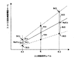
図6はデータ線駆動電流検出モードにおいてコントローラより入力される画像信号レベルとデータ線駆動電流検出回路10より検出される電流検出レベルとの関係を示す特性図である。図において、点線は基準レベルRef(1)及びRef(2)よりも電流検出レベルが大きいデータ線、一点鎖線は基準レベルRef(1)及びRef(2)よりも電流検出レベルが小さいデータ線についての一例を示している。データ線駆動電流検出モードにおいては、第1の入力レベルK1に対応するデータ線駆動電流検出レベルD(1)と基準レベルRef(1)との誤差検出信号E(1)、及び第2の入力レベルK2に対応するデータ線駆動電流検出レベルD(2)と基準レベルRef(2)との誤差検出信号E(2)とが各データ線毎にメモリ18にストアされている。
このように、データ線駆動電流検出モード時に、第1及び第2のレベルに対応した検出結果D(1),D(2)と基準レベルRef(1),Ref(2)との差分のみを誤差検出信号E(1),E(2)としてメモリ回路18へストアし、表示モード時に、誤差検出信号E(1),E(2)をメモリ回路18から読み出して入力画像信号の補正に用いるので、検出結果を保持するためのメモリ容量を低減することが可能となる。
【0052】
このとき、データ補正回路17においては、各データ線に対応する誤差検出信号E(1)及びE(2)に基づいて、画像信号レベル(階調レベル)がkの場合の当該データ線における駆動電流の検出誤差E(k)を下式に示す線形予測(線形補間)により求める。ここでは、例えば画像信号を6ビットとしているので、0≦k≦63の値となる。
まず、データ補正回路17では、入力される6ビットの画像信号R[5..0]、G[5..0]、B[5..0]を例えば10ビットの信号r[9..0]、g[9..0]、b[9..0]に予め変換してビット拡張を行っておく。ここでは、変換後の信号レベルso(k)として下式(1)に示す変換係数αの線形変換を行う。
【0053】
so(k)=α・k ・・・式(1)
ここでは、さらに簡単のため、それぞれ左4ビットシフトにより変換するものとすれば、α=16となる。
【0054】
そして、誤差検出信号E(1)及びE(2)に基づいて、画像信号レベルkにおける誤差信号E(k)を下式(2)により補間して求める。
E(k)=((E(2)−E(1))/(K2−K1))・(k−K1)+E(1) ・・・式(2)
ここで誤差信号の検出を行ってある画像信号レベルに対応する誤差信号は特に補間により求める必要はなく、そのまま誤差信号として用いればよい。
【0055】
次に、画像信号に対する補正値e(k)を下式(3)により求める。
e(k)=E(k)/G ・・・式(3)
但し、G:データ補正回路17の出力レベルに対するA/D変換回路21出力レベルの変換係数。
【0056】
そして、この変換されたso(k)に対して、下式(4)の処理を行う。
Si(k)=so(k)−e(k) ・・・式(4)
但し、Si(k):入力画像信号レベルkのときのデータ補正回路17出力信号レベル。
【0057】
このように、本実施の形態1においては、各データ線(各列)の駆動電流に対して図7(a)に示すような一種のフィードバック制御系を構成していると考えても良い。すなわち、データ線駆動電流検出モードにおいては、図7(b)に示す処理系が構成され、コントローラ回路から2つのレベルの入力画像信号(レベルK1、K2)がデータ補正回路17に入力され、上述の式(3)に従って例えば10bitの信号(レベルso(1)、so(2))に変換され、データ補正回路17の出力信号(第1のレベルK1、第2のレベルK2)としてD/A変換回路16へ送られる。D/A変換回路16においてアナログ電流に変換された後(変換係数をG1とする)、有機EL表示パネル15へ入力され、データ線駆動回路3にてデータ線駆動電流Idとしてデータ線を駆動する。ここで、データ線駆動回路3の特性のばらつきがデータ線駆動電流のばらつきとなって現れるので、データ線駆動回路3の変換係数は列毎に異なる。
【0058】
このとき、上述したように、垂直走査回路8は動作を停止しており、データ線駆動電流Idは画素回路7に供給されること無く、データ線駆動電流検出回路9にて検出され(変換係数をG3)、電流検出出力信号(レベルD(1)、D(2))としてA/D変換回路21にてA/D変換された後(変換係数をG4とする)、誤差検出回路20へ入力される。
誤差検出回路20では、2つのレベルD(1)及びD(2)の電流検出信号とそれぞれ第1及び第2のレベルに対応する基準レベルRef(1)及びRef(2)との差分がとられ、誤差検出信号E(1)及びE(2)としてメモリ回路18にストアされる。
【0059】
上述したようにこのような処理が全部のデータ線にわたって行われ、各データ線毎に、第1及び第2のレベルの信号を入力したときのそれぞれの誤差検出信号E(1)及びE(2)としてメモリ回路18へストアされる。
そして、表示モードにおいては、上述したように、各RGB列毎に表示すべきデータに対応した電流がデータ線駆動回路3へ順次書き込まれる。このとき、各データ線に対して、図7(c)に示す処理系が構成され、メモリ回路18から読み出された当該データ線における誤差検出信号E(1)及びE(2)から、上述の式(2)に従って、表示すべき画像信号レベルに対応した誤差信号E(k)が線形予測(線形補間)により求められる。本実施の形態における式(2)に基づく線形補間の変換係数β=1である。そして、上述の式(3)に従って、レベルが変換された誤差信号e(k)が求められる。
【0060】
ここで、上述のデータ補正回路17の出力レベルに対するA/D変換回路21出力レベルの変換係数Gは、
G=G1・G2・G3・G4
で示される。
但し、G2:基準レベルRef(1)及びRef(2)から求められるデータ線駆動回路3の変換係数。
【0061】
一方、コントローラから入力される画像信号は、そのレベルに応じて上述の式(1)に従ってビット拡張され、上述の式(4)に従って、誤差が補正された補正データSi(k)としてD/A変換回路16に送られる。そして、D/A変換回路16においてアナログ電流に変換された後、有機EL表示パネル15へ入力され、誤差を補正された表示すべきデータに対応した電流として各列のデータ線駆動回路3へ順次書き込まれる。
そして次のライン期間において、各データ線駆動回路3は、データ線駆動電流IR(1)、IG(1)、IB(1)、・・・、IR(m)、IG(m)、IB(m)、・・・、IR(M−1)、IG(M−1)、IB(M−1)を、各列共通のタイミングにて各データ線4へ出力する。
【0062】
以上のように、本実施の形態1においては、第1及び第2のレベルの入力画像信号をそれぞれ入力したときの検出結果と第1及び第2のレベルに対応した基準検出結果との差分を誤差検出結果として、それに基づいて表示すべき画像信号を補正するよう構成したので、第1及び第2のレベル以外の画像信号を入力したときの信号線駆動電流の誤差を線形補間により容易に求めることができ、データ線駆動回路を形成するTFTの特性ばらつきによるデータ線駆動電流のばらつきを抑えることができ、表示のムラを改善することが可能となる。
【0063】
実施の形態2.
上記の実施の形態1においては、入力画像信号に対するデータ線駆動電流が線形特性であることを前提として、2点の誤差検出信号E(1)、E(2)により補正するよう構成した。
ところが、特に表示のガンマ補正を行う場合など、入力画像信号に対するデータ線駆動電流が非線形特性の関係となることがある。このように、入力画像信号に対するデータ線駆動電流が非線形特性となる形態につき、以下実施の形態2として説明する。
【0064】
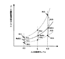
図8は実施の形態2におけるデータ線駆動電流検出モード時にコントローラより入力される画像信号レベルとデータ線駆動電流検出回路10より検出される電流検出レベルとの関係を示す図である。
データ補正回路17においては、画像信号レベルkの取り得る値(画像信号を6ビットとすれば、0≦k≦63の全ての整数値。)について、予め、基準レベルRef(0)、Ref(1)、・・・、Ref(63)を設定しておく。
【0065】
そして、誤差検出信号E(1)及びE(2)に基づいて、画像信号レベルkにおける誤差信号E(k)を下式(5)に従った補間により求める。
E(k)=(E(2)−E(1))
×((Ref(k)−Ref(1))/(Ref(2)−Ref(1)))+E(1)・・・式(5)
ここで、誤差信号の検出を行ってある画像信号レベルに対応する誤差信号は特に補間により求める必要はなく、そのまま誤差信号として用いればよい。
その他の構成及び動作は実施の形態1にて説明したのと同様であるので、詳しい説明は省略する。
【0066】
以上のように、本実施の形態2においては、画像信号レベルの取り得る値について、予め、基準検出結果を設定しておき、第1及び第2のレベルの表示すべき画像信号をそれぞれ入力したときの上記検出結果と対応する画像レベルの基準検出結果との差分を誤差検出結果として、それに基づいて表示すべき画像信号を補正するよう構成したので、第1及び第2のレベル以外の画像信号を入力したときの信号線駆動電流の誤差を補間により容易に求めることができ、それに基づいて入力画像信号を補正するので、信号線駆動手段を形成するTFTの特性ばらつきによる信号線駆動電流のばらつきを抑えることが可能となり、表示のムラを改善することができる。また、第1及び第2のレベルに対応した検出結果の基準検出結果との差分のみを入力画像信号の補正に用いるので、検出結果を保持するためのメモリ容量を低減することが可能となる。
【0067】
実施の形態3.
実施の形態1においては、入力画像信号に対するデータ線駆動電流が線形特性であることを前提として、2点の誤差検出信号E(1)、E(2)により入力画像信号に対応する誤差信号を補間して求めるよう構成した。ところが、特に表示のガンマ補正を行う場合など、入力画像信号に対するデータ線駆動電流が非線形特性となることがある。この場合、実施の形態1における2点の誤差検出信号による線形補間では補正が不十分となることがある。
ここでは、補正の精度をより向上させることのできる多点の誤差検出信号による補正を行う場合の形態につき説明する。
【0068】
本実施の形態3における電流検出モードでは、実施の形態1において図4をもとに説明したデータ線駆動回路3への書込み→データ線駆動電流検出→誤差信号のメモリ回路18への書込みという一連のシーケンスを、入力画像信号レベルをK1、K2、・・・、KNとして順次繰り返すことになる(3≦N≦63)。
【0069】
図9は実施の形態3におけるデータ線駆動電流検出モード時にコントローラより入力される画像信号レベルとデータ線駆動電流検出回路10より検出される電流検出レベルとの関係を示す図である。図は、画像信号レベルkがK1とK2の間の区間にある場合を示している。
【0070】
データ補正回路17においては、画像信号レベルkが、誤差信号を検出しているN点のうち、どの2点の間の区間にあるかを判別する。
例えば、画像信号レベルkがKnとKn+1の間にある場合、実施の形態1で示した式(2)、あるいは実施の形態2で示した式(5)と同様にして、誤差検出信号E(n)及びE(n+1)に基づいて、画像信号レベルkにおける誤差信号E(k)を下式(6)もしくは下式(7)に従った補間により求める。
E(k)=((E(n+1)−E(n))/(Kn+1−Kn))・(k−Kn)+E(n) ・・・式(6)
E(k)=(E(n+1)−E(n))
×((Ref(k)−Ref(n))/(Ref(n+1)−Ref(n)))+E(n)・・・式(7)
誤差信号の検出を行ってある画像信号レベルに対応する誤差信号は特に補間により求める必要はなく、そのまま誤差信号として用いればよい。
その他の構成及び動作は実施の形態1にて説明したのと同様であるので、詳しい説明は省略する。
【0071】
以上のように、本実施の形態3においては、N種類のレベル(3≦N≦表示階調数)の入力画像信号をそれぞれ入力したときの検出結果とN種類のレベルに対応した基準検出結果との差分を誤差検出結果するとともに、入力画像信号のレベルがN種類のレベルうちの隣接する2つのレベルの間におけるいずれの区間にあるかを判別して、該隣接する2つのレベルに対応した各列の誤差検出結果に基づいて表示すべき画像信号を補正する。これにより、特に、入力画像信号に対するデータ線駆動電流が非線形特性の関係となる場合においても、N種類のレベル以外の画像信号を入力したときのデータ線駆動電流の誤差を線形補間により容易に求めることができ、それに基づいて入力画像信号を補正するので、データ線駆動回路を形成するTFTの特性ばらつきによるデータ線駆動電流のばらつきを抑えることが可能となり、表示のムラを改善することができる。
【0072】
実施の形態4.
上記の各実施の形態1〜3においては、2点もしくは多点の誤差検出信号より入力画像信号に対応する誤差信号を補間して求めるよう構成した。本実施の形態4においては、さらに精度よく画像信号の補正ができるように入力画像信号レベルの取り得る値全てに対応した誤差信号を検出するように構成する。
【0073】
本実施の形態4における電流検出モードでは、実施の形態1において図4をもとに説明したデータ線駆動回路3への書込み→データ線駆動電流検出→誤差信号のメモリ回路18への書込みという一連のシーケンスを、入力画像信号レベルの取り得る値(上記各実施の形態1〜3同様に、入力画像信号を6ビットとすると、0≦k≦63の全ての整数値。)の全てにわたって順次繰り返すことになる。そして、検出された画像信号に対応する各誤差信号をメモリ回路18へストアする。
【0074】
表示モードにおいては、上記各実施の形態1〜3による誤差信号の補間処理が省略されるが、その他の構成及び動作は実施の形態1にて説明したのと同様であるので、詳しい説明は省略する。
また、上記実施の形態1において図7をもとに説明した処理系の構成についても、式(2)に従った補間処理のブロックが省略されるだけで、他は上記実施の形態2、3で説明したものと同様の構成である。
【0075】
以上のように、本実施の形態4においては、表示すべき画像信号の取り得る全てのレベルをそれぞれ入力したときの各列の誤差検出結果に基づいて表示すべき画像信号を補正するので、入力画像信号をより精度良く補正することが可能となり、データ線駆動回路を形成するTFTの特性ばらつきによるデータ線線駆動電流のばらつきをより効果的に抑えることが可能となり、表示のムラを改善することができる。
【0076】
実施の形態5.
実施の形態1にて説明したように、表示装置に用いられる有機EL表示パネル15は、シフトレジスタ回路1、データ線駆動回路3、画素回路6R,6B,6G、垂直走査回路8、データ線駆動電流検出回路9を内蔵しており、これらの回路は例えばガラス基板上に低温多結晶シリコンTFTにより形成されている。さらに、画素回路6R、6G、6Bの画素電極(図示せず)上に有機EL層が蒸着等により形成されている。低温多結晶シリコンTFTにて回路が構成された基板は一般にアレイ基板と呼ばれる。
有機EL表示パネル15を製造する際に、データ線駆動回路3から出力されるデータ線駆動電流のばらつきの度合いにより、例えば、画素電極上に有機EL層が形成される前の工程において、アレイ基板の良品/不良品の検査を行うことができる。
すなわち、アレイ基板製造工程における良品検査において、実施の形態1の電流検出モードに必要な画像信号や制御信号を外部の検査装置より入力し、データ線検出回路9により検出された各列のデータ線駆動電流検出レベルの偏差が所定の範囲にある場合にはアレイ基板を良品、所定の範囲から外れる場合には不良品と判別することができる。
【0077】
なお、実施の形態2〜4においては、6ビットの入力画像信号を10ビットの信号へビット拡張を線形変換ではなく、例えばルックアップテーブルを参照することによるガンマ補正処理を兼ねるように構成することも可能である。
【0078】
また、上記実施の形態1〜4において、画像信号レベルk=0のときは、コントラスト比を高めるという観点から有機EL素子を消灯するためにデータ線駆動回路3からのデータ線駆動電流を供給しないように制御することが望ましい。このため、画像信号レベルk=0の場合、すなわち、全黒表示の場合には、特にデータ線駆動電流のばらつきを補正する必要がないことも有り得る。このような場合には、画像信号レベルk=0のときには、データ補正回路17における画像信号の補正処理を行なわないように構成しても良い。
【0079】
また、上記実施の形態2〜4においては、特に入力画像信号に対するデータ線駆動電流が非線形特性となる場合につき説明したが、要求される補正の制度との兼ね合いで、入力画像信号の一部を実施の形態1で示した線形補間により補正する、すなわち実施の形態1と組み合わせた形態をとることも可能である。
さらには、
【0080】
また、メモリ回路18としては、EPROM(Erasable Programmable Read Only Memory)やEEPROM(Electrically Erasable Programmable Read OnlyMemory)等の不揮発性メモリやSRAM(Static Random Access Memory)やDRAM(Dynamic Random Access Memory)等の揮発性メモリを用いることができる。
【0081】
不揮発性メモリを用いる場合には、例えば装置の出荷時に電流検出モードを実行し、各列の誤差検出信号をメモリ回路18へ書き込むようにすれば良い。また、揮発性メモリを用いる場合には、例えば装置の起動時に電流検出モードを実行し、各列の誤差検出信号をメモリ回路18へ書き込むようにすれば良い。
【0082】
また、D/A変換回路16、データ補正回路17、メモリ回路18、メモリ制御回路19、誤差検出回路20、A/D変換回路21はコントローラと一体のASIC(Application Specific IC)等として構成することが可能である。
また、データ補正回路17や誤差検出回路20の動作は、マイクロプロセッサ等によるソフトウェア処理によっても行うことが可能である。
【0083】
さらに、上記各実施の形態1〜5においては、発光素子を有機EL素子として説明したが、電流により発光輝度が変化するLED(Light Emitting Diode)やFE(Field Emitter)の他の電流制御型素子を用いた表示装置においても本発明を適用できることも言うまでもない。
【0084】
【発明の効果】
本発明の第1の構成による表示装置は、画素マトリクス回路の各列の上記信号線へ供給される信号電流を検出して検出結果として順次出力し、その検出結果に基づいて表示すべき画像信号を補正するよう構成したので、信号線駆動手段を形成するTFTの特性ばらつきによる信号線駆動電流のばらつきを抑えることができる。
【0085】
本発明の第2の構成による表示装置は、上記第1の構成において、各列の信号線のそれぞれに一端が接続され各列毎に設けられたスイッチ回路を順次導通するように構成したので、電流検出線の本数を削減することができ、表示パネルから検出結果を出力する場合には、その取り出し用端子の数も削減することが可能となる。
【0086】
本発明の第3の構成による表示装置は、上記第2の構成において、信号電流検出手段が、電流検出線に現れる各列の信号電流を所定の電流比により増幅したのち、電圧に変換して出力するよう構成したので、出力インピーダンスを下げることができ、ノイズの影響を低減して精度良く信号線駆動電流を検出して出力することが可能となる。
【0087】
本発明の第4の構成による表示装置は、上記第1の構成におて、第1及び第2のレベルの表示すべき画像信号をそれぞれ入力したときの上記検出結果と第1及び第2のレベルに対応した基準検出結果との差分を誤差検出結果として、それに基づいて表示すべき画像信号を補正するよう構成したので、第1及び第2のレベル以外の画像信号を入力したときの信号線駆動電流の誤差を線形補間により容易に求めることができ、信号線駆動手段を形成するTFTの特性ばらつきによる信号線駆動電流のばらつきを抑えることが可能となる。
【0088】
本発明の第5の構成による表示装置は、上記第1の構成において、N種類のレベル(3≦N≦表示階調数)の表示すべき画像信号をそれぞれ入力したときの検出結果とN種類のレベルに対応した基準検出結果との差分を誤差検出結果するとともに、表示すべき画像信号のレベルがN種類のレベルうちの隣接する2つのレベルの間のいずれの区間にあるかを判別して、該隣接する2つのレベルに対応した各列の誤差検出結果に基づいて表示すべき画像信号を補正するよう構成したので、特に、入力画像信号に対する信号線駆動電流が非線形特性の関係となる場合においても、N種類のレベル以外の画像信号を入力したときの信号線駆動電流の誤差を線形補間により容易に求めることができ、信号線駆動手段を形成するTFTの特性ばらつきによる信号線駆動電流のばらつきを抑えることが可能となる。
【0089】
本発明の第6の構成による表示装置は、上記第1の構成において、表示すべき画像信号の取り得る全てのレベルをそれぞれ入力したときの各列の誤差検出結果に基づいて表示すべき画像信号を補正するよう構成したので、入力画像信号をより精度良く補正することが可能となり、信号線駆動手段を形成するTFTの特性ばらつきによる信号線駆動電流のばらつきをより効果的に抑えることが可能となる。
【0090】
本発明の第7の構成による表示装置は、上記第1の構成において、信号電流検出手段により信号電流を検出するときには走査手段を停止するよう構成したので、画素回路への信号線駆動電流の分流を回避して信号線駆動電流を精度よく確実に検出することが可能となる。
【0091】
本発明の第8の構成による表示装置は、上記第4〜6のいずかの構成において、誤差検出結果を保持するメモリ手段を備えたので、各列の信号線に供給される信号電流の誤差検出結果をメモリ手段に書き込む動作モードと、表示すべき画像信号を上記補正手段により補正して画素マトリクスに表示する動作モードとを時間的に分離することができ、前者の動作モードを装置起動時等に実行することが可能となる。
【0092】
本発明による表示パネルは、各画素の発光素子に電流を供給する画素マトリクス回路と、画素マトリクス回路へ信号電流を供給する信号線と、表示すべき画像信号を信号電流として信号線へ出力する信号線駆動手段と、画素マトリクス回路の各列の信号線へ供給される信号電流を検出し、検出結果として順次出力する信号電流検出手段を備えたので、信号線駆動電流のばらつきの度合いにより、アレイ基板の良品/不良品の検査を行うことができる。
【図面の簡単な説明】
【図1】本発明の実施の形態1による表示装置の構成を示すブロック図である。
【図2】本発明の実施の形態1による表示装置におけるデータ線駆動回路の構成を示す回路図である。
【図3】本発明の実施の形態1による表示装置における画素回路の構成を示す回路図である。
【図4】本発明の実施の形態1による表示装置におけるデータ線駆動電流検出モードの動作シーケンスを示す波形図である。
【図5】本発明の実施の形態1による表示装置におけるデータ線駆動電流検出回路の構成を示す回路図である。
【図6】本発明の実施の形態1による表示装置におけるデータ線駆動電流検出モードの入力画像信号レベルと電流検出レベルとの関係を示す特性図である。
【図7】本発明の実施の形態1による表示装置における処理系の構成を示すブロック図である。
【図8】本発明の実施の形態2による表示装置におけるデータ線駆動電流検出モードの入力画像信号レベルと電流検出レベルとの関係を示す特性図である。
【図9】本発明の実施の形態3による表示装置におけるデータ線駆動電流検出モードの入力画像信号レベルと電流検出レベルとの関係を示す特性図である。
【符号の説明】
3 データ線駆動回路、4 データ線(信号線)、5 画素マトリクス、8 垂直走査回路、9 データ線駆動電流検出回路、10 スイッチ回路、11 電流検出線、12 セレクト回路、13 シフトレジスタ回路、14 電流−電圧変換回路、15 有機EL表示パネル、17 データ補正回路、18 メモリ回路、20 誤差検出回路。[0001]
TECHNICAL FIELD OF THE INVENTION
The present invention relates to a display device having a light emitting element whose light emission luminance changes by a current such as an organic EL (Electro Luminescence) in each pixel, and a display panel used for the same.
[0002]
[Prior art]
2. Description of the Related Art In recent years, display devices using an organic EL as a light emitting element have been actively developed for portable information terminals and retail vision receivers. A self-luminous display device having a light emitting element such as an organic EL in each pixel has excellent visibility and excellent moving image display characteristics.
In particular, in an active display device using a thin film transistor (TFT) formed on a glass substrate as a switching element of a pixel, a current is applied to a light emitting element until the next rewriting based on a rewritten signal. Since the current can be continuously supplied, there is an advantage that high luminance can be obtained with a drive current to a light emitting element smaller than a passive type in which a switching element is not used in a pixel.
[0003]
The conventional display device includes a scanning line driving circuit for sequentially selecting the scanning lines scanA and scanB, and a current source CS for generating a signal current Iw having a current level corresponding to the luminance information and sequentially supplying the signal current Iw to the data line data. A data line driving circuit and a plurality of pixels including a current driving type light emitting element OLED which is arranged at an intersection of each of the scanning lines scanA and scanB and each of the data lines data and emits light by receiving a driving current are provided. Have. As a feature, the pixel is configured to receive the signal current Iw from the data line data when the scan line scanA is selected, and to convert the current level of the received signal current Iw into a voltage level once and hold it. And a drive unit that supplies a drive current having a current level corresponding to the held voltage level to the light emitting element OLED (for example, see Patent Document 1).
[0004]
[Patent Document 1]
JP 2001-147659 A (pages 7-9, FIGS. 1 and 5)
[0005]
[Problems to be solved by the invention]
Among the thin film transistors, low-temperature polycrystalline silicon TFTs (low-temperature p-Si TFTs) that can be manufactured by a low-temperature process have higher mobility than amorphous silicon TFTs. Since it can be formed integrally with a circuit, it has been widely used, including a liquid crystal display device.
However, a low-temperature p-Si TFT is generally formed by laser annealing. However, it is difficult to uniformly control the laser irradiation intensity within the glass substrate surface. It is known that characteristics such as (mobility) vary greatly.
[0006]
In a conventional display device, when a data line drive circuit is integrated with a pixel matrix on a glass substrate using TFTs in a display panel, the data line (signal line) drive current of each column varies due to variations in TFT characteristics. This causes a problem that unevenness in the form of vertical stripes or vertical bands occurs in the emission luminance.
[0007]
The present invention has been made to solve the above-described problem, and can suppress variation in signal line drive current in each column and suppress unevenness in light emission luminance even when variation in TFT characteristics is large. It is intended to obtain a display device.
[0008]
Another object of the present invention is to provide a display panel that can detect a variation in signal line drive current and easily perform a non-defective / defective screening test when manufacturing a display panel or a display device.
[0009]
[Means for Solving the Problems]
The display device according to the first configuration of the present invention includes a pixel matrix circuit for supplying a current to the light emitting element of each pixel, a signal line for supplying a signal current to the pixel matrix circuit, and an image signal to be displayed. Signal line driving means for outputting to the signal line as a current, signal current detecting means for detecting the signal current supplied to the signal line of each column of the pixel matrix circuit, and sequentially outputting the signal current as a detection result; Correction means for correcting the image signal to be displayed based on the detection result detected by the current detection means.
[0010]
Further, in the display device according to the second configuration of the present invention, in the first configuration, the switch circuit provided as one of the signal lines in each of the columns and having one end connected to each of the signal lines in each of the columns. And a current detection line to which the other end of the switch circuit is connected in common, and switch control means for controlling the switch circuit to conduct sequentially.
[0011]
Further, in the display device according to the third configuration of the present invention, in the second configuration, the signal current detection unit amplifies a signal current of each column appearing on the current detection line by a predetermined current ratio, And a current-voltage conversion means for converting the current into a voltage.
[0012]
Further, in the display device according to the fourth configuration of the present invention, in the first configuration, the detection result when the image signals to be displayed at the first and second levels are input and the first and second image signals, respectively. Error detection means for outputting a difference from a reference detection result corresponding to the second level as an error detection result, wherein the correction means is configured to output the difference based on the error detection result of each column corresponding to the first and second levels. Thus, the image signal to be displayed is corrected.
[0013]
Further, in the display device according to the fifth configuration of the present invention, in the first configuration, the detection is performed when the image signals to be displayed at N levels (3 ≦ N ≦ the number of display gradations) are input. Error detecting means for outputting a difference between a result and a reference detection result corresponding to the N kinds of levels as an error detection result, wherein the correcting means is adapted to make the level of the image signal to be displayed out of the N kinds of levels Is determined in which section between two adjacent levels, and the image signal to be displayed is corrected based on the error detection result of each column corresponding to the two adjacent levels. is there.
[0014]
Further, in the display device according to the sixth configuration of the present invention, in the first configuration, the correction unit may detect the error of each column when all possible levels of the image signal to be displayed are input. The image signal to be displayed is corrected based on the result.
[0015]
Further, in the display device according to the seventh configuration of the present invention, in the first configuration, the display device further includes a scanning unit that sequentially scans the pixel matrix circuit, and the scanning unit is used when the signal current detection unit detects the signal current. Is to stop.
[0016]
Further, in the display device according to the eighth configuration of the present invention, in any one of the fourth to sixth configurations, the display device further includes a memory unit that stores the error detection result.
[0017]
A display panel according to another aspect of the present invention includes a pixel matrix circuit for supplying a current to a light emitting element of each pixel, a signal line for supplying a signal current to the pixel matrix circuit, and an image signal to be displayed as the signal current. Signal line driving means for outputting to the signal line; and signal current detecting means for detecting the signal current supplied to the signal line of each column of the pixel matrix circuit and sequentially outputting the signal current as a detection result. .
[0018]
BEST MODE FOR CARRYING OUT THE INVENTION
FIG. 1 is a block diagram showing a configuration of the display device according to the first embodiment of the present invention. In the figure, 1 is a shift register circuit, 2R, 2G, and 2B are input signal lines for R, G, and B to which analog image signals of RGB are supplied, respectively, 3 is a data line driving circuit, and 4 is a data line. (Signal line) 5, 5 is a pixel matrix in which RGB pixels are arranged in a matrix, 6R, 6B, and 6G are R, G, and B pixel circuits, respectively, 7 is a pixel, 8 is a vertical scanning circuit, and 9 is data. Line drive current detection circuit, 10 is a switch circuit, 11 is a current detection line, 12 is a select circuit, 13 is a shift register circuit, 14 is a current-voltage conversion circuit, 15 is an organic EL display panel, and 16 is a D / A conversion circuit. , 17 is a data correction circuit, 18 is a memory circuit, 19 is a memory control circuit, 20 is an error detection circuit, and 21 is an A / D conversion circuit.
[0019]
Here, for example, a case will be described in which 260,000 colors are displayed using image data of 6 bits for each of R (Red), G (Green), and B (Blue). In addition, the figure shows a configuration for each of two columns of RGB, and a suffix m indicates that it corresponds to, for example, the m-th RGB column from the left (a set of RGB columns).
Further, the
[0020]
Next, the operation will be described. In the first embodiment, the input digital image signal R [5. . 0], G [5. . 0], B [5. . 0], and a data line drive current detection for detecting a drive current of each
[0021]
An image signal R to be displayed input from a controller circuit (not shown) [5. . 0], G [5. . 0], B [5. . [0] is subjected to a predetermined correction by the data correction circuit 17 (the correction method will be described later), and then converted to an analog current by the D / A conversion circuit 16 and supplied to each color
On the other hand, a start pulse STH and a shift clock CLKH are input to the
[0022]
.., SH (m),... SH (M−1) output from the
Here, the data
[0023]
In the figure,
[0024]
The system A
The drain of the
[0025]
The drain of the TFT 323a is connected to the
Further, the system B
[0026]
For example, when the system A output enable signal EN_A is inactive (“L” level) and the system B output enable signal EN_B is active (“H” level), the output signal of the AND
[0027]
Then, when the sampling pulse SH (m) of the column becomes “L” level, the
When the system A output enable signal EN_A becomes active (“H” level), the
[0028]
At this time, from when the current supply from the
[0029]
Therefore, a
[0030]
Thereby, in the display mode, when the driving
The system B
[0031]
Next, the
FIG. 3 is a diagram illustrating a configuration of the
[0032]
Then, during the EL light emitting element driving operation, when the scan line B goes to the “L” level and then the scan line A goes to the “L” level, the gates of the
[0033]
Returning to FIG. 1, a start pulse STV and a shift clock CLKV are input to the
As described above, in the display mode, the current corresponding to the image for one line display supplied to the
[0034]
Next, the operation in the data line drive current detection mode will be described.
FIG. 4 is a waveform chart showing an operation sequence in the data line drive current detection mode. First, in the data line drive current detection mode, the supply of the start pulse STV and the shift clock CLKV from the controller circuit (not shown) is stopped (for example, both control signals are fixed to the “L” level), thereby making the vertical scanning circuit.
On the other hand, similarly to the display mode, the start pulse STH and the shift clock CLKH are supplied from the controller circuit to the
[0035]
Also, a 6-bit digital signal having the first level (magnitude) K1 is output from the controller circuit to the digital image signal R [5. . 0], G [5. . 0], B [5. . 0] to the
[0036]
At this time, the system A output enable signal EN_A is inactive ("L" level) and the system B output enable signal EN_B is active ("H" level), which is input from the controller, and is generated by these output enable signals and the shift register. In the same manner as in the display mode, the shift pulse is sequentially supplied to the
[0037]
After that, the operation shifts to a current detection operation for detecting the drive current of the
In the drive current detection operation for the
[0038]
FIG. 5 shows the configuration of the data line drive current detection circuit. Data lines 4 (hereinafter, referred to as
[0039]
The shift pulse ST (m) corresponding to the column and the R select signal SLR are input to the AND
Similarly, the shift pulses ST (m) and the select signals SLG and SLB for G and B are connected to the AND
Here, as shown in FIG. 4, first, a start pulse STT of the shift register 13 and a shift clock CLKT are input from a controller (not shown) by activating the R select signal SLR ("H" level). The
[0040]
On the other hand, a current mirror circuit 55 is connected to the
[0041]
Here, since the current value for driving the data line is generally a very small current of the order of μA or less, if the current is output by the current mirror circuit 55 as it is, a voltage is required to secure the detection sensitivity of the A / D conversion circuit 21 at the subsequent stage. If an attempt is made to increase the value, the resistance value of the current detecting
Further, one end is connected to each of the data lines of each column, and the switch circuits provided for each column are controlled so as to be sequentially turned on, and the signal current of each column appearing on the current detection line is sequentially output as a detection result. With this configuration, the number of current detection lines can be reduced, and the number of terminals for extracting a current detection result from the organic
[0042]
The result of detecting the drive current of each
Similarly, as shown in FIG. 4, the digital image signal of the first level K1 is output to the
[0043]
Then, the select signal SLG is made active (“H” level), and the drive current of the
Further, after sequentially performing a current writing operation to the system A
[0044]
As described above, the data line drive current detection circuit 9 determines the drive current when the system A
Next, as shown in FIG. 4, the digital image signal of the second input level K2 is supplied from the controller to the
[0045]
Further, the output enable signal EN_A is made active (“H” level), the output enable signal EN_B is made inactive (“L” level), and the data line of each column is connected to the system B current with a current corresponding to the first input level K1. After writing to the source circuit 320b, the drive current when each data line is driven by the system B current source circuit 320b by setting the output enable signal EN_A to inactive (“L” level) and EN_B to active (“H” level). Is detected by the data line drive current detection circuit 9 and the result is stored in the
[0046]
Then, a current corresponding to the second input level K2 is input to the
As described above, in the data line drive current detection mode, the system A and B
[0047]
By the way, during the current detection period in the data line drive current detection mode, the shift pulse ST is not used when the
[0048]
Therefore, in the first embodiment, even during the current detection period in the data line drive detection mode, not only the
At this time, since the current detection identification signal DET is active ("H" level), the shift pulses SH (0), ..., SH (m), ..., SH (M-1) are output to the AND circuit 311a. , 311b to control the gate potentials of the
[0049]
In other words, even during the current detection period in the data line drive current detection mode, the output of the
Accordingly, the dummy loads 325a and 325b are connected to the outputs of the driving
[0050]
Next, a method of correcting the input digital image signal based on the error signal E of the detection result of the data line driving current stored in the
[0051]
FIG. 6 is a characteristic diagram showing the relationship between the image signal level input from the controller and the current detection level detected by the data line drive
As described above, in the data line drive current detection mode, only the differences between the detection results D (1) and D (2) corresponding to the first and second levels and the reference levels Ref (1) and Ref (2) are determined. The error detection signals E (1) and E (2) are stored in the
[0052]
At this time, in the
First, in the
[0053]
so (k) = α · k Expression (1)
Here, for further simplification, α = 16 if the conversion is performed by shifting left by 4 bits.
[0054]
Then, based on the error detection signals E (1) and E (2), the error signal E (k) at the image signal level k is obtained by interpolation using the following equation (2).
E (k) = ((E (2) −E (1)) / (K2−K1)) · (k−K1) + E (1) Equation (2)
Here, the error signal corresponding to the image signal level for which the error signal has been detected does not need to be obtained by interpolation in particular, and may be used as it is as the error signal.
[0055]
Next, a correction value e (k) for the image signal is obtained by the following equation (3).
e (k) = E (k) / G Equation (3)
Here, G is a conversion coefficient of the output level of the A / D conversion circuit 21 with respect to the output level of the
[0056]
Then, the processing of the following equation (4) is performed on the converted so (k).
Si (k) = so (k) -e (k) Equation (4)
Here, Si (k): the output signal level of the
[0057]
As described above, in the first embodiment, a kind of feedback control system as shown in FIG. 7A may be considered for the drive current of each data line (each column). That is, in the data line drive current detection mode, the processing system shown in FIG. 7B is configured, and two levels of input image signals (levels K1 and K2) are input to the
[0058]
At this time, as described above, the
In the
[0059]
As described above, such processing is performed on all data lines, and error detection signals E (1) and E (2) when signals of the first and second levels are input for each data line. ) Is stored in the
Then, in the display mode, as described above, the current corresponding to the data to be displayed for each of the RGB columns is sequentially written to the data line driving
[0060]
Here, the conversion coefficient G of the output level of the A / D conversion circuit 21 with respect to the output level of the
G = G1, G2, G3, G4
Indicated by
Here, G2 is a conversion coefficient of the data line driving
[0061]
On the other hand, the image signal input from the controller is bit-extended according to the above equation (1) according to the level, and D / A is output as corrected data Si (k) in which the error is corrected according to the above equation (4). It is sent to the conversion circuit 16. Then, after being converted into an analog current by the D / A conversion circuit 16, the analog current is input to the organic
In the next line period, each data
[0062]
As described above, in the first embodiment, the difference between the detection result when the first and second level input image signals are input and the reference detection result corresponding to the first and second levels is calculated. Since the image signal to be displayed is corrected based on the error detection result, an error in the signal line driving current when an image signal other than the first and second levels is input is easily obtained by linear interpolation. Thus, variation in data line drive current due to variation in characteristics of TFTs forming the data line drive circuit can be suppressed, and display unevenness can be improved.
[0063]
In the first embodiment, on the assumption that the data line driving current for the input image signal has a linear characteristic, the correction is performed by the two error detection signals E (1) and E (2).
However, the data line driving current with respect to the input image signal may have a non-linear characteristic relationship, particularly when performing gamma correction of display. An embodiment in which the data line driving current corresponding to the input image signal has non-linear characteristics will be described below as a second embodiment.
[0064]
FIG. 8 is a diagram showing the relationship between the image signal level input from the controller and the current detection level detected by the data line driving
In the
[0065]
Then, based on the error detection signals E (1) and E (2), the error signal E (k) at the image signal level k is obtained by interpolation according to the following equation (5).
E (k) = (E (2) -E (1))
× ((Ref (k) −Ref (1)) / (Ref (2) −Ref (1))) + E (1) Equation (5)
Here, the error signal corresponding to the image signal level at which the error signal has been detected does not need to be obtained by interpolation in particular, and may be used as it is as the error signal.
Other configurations and operations are the same as those described in the first embodiment, and a detailed description thereof will be omitted.
[0066]
As described above, in the second embodiment, the reference detection results are set in advance for possible values of the image signal level, and the image signals to be displayed at the first and second levels are input, respectively. The difference between the above detection result and the corresponding image level reference detection result is used as an error detection result, and the image signal to be displayed is corrected based on the error detection result. Therefore, image signals other than the first and second levels are corrected. The error of the signal line driving current when the signal line is input can be easily obtained by interpolation, and the input image signal is corrected based on the error. Therefore, the variation of the signal line driving current due to the characteristic variation of the TFT forming the signal line driving means. Can be suppressed, and display unevenness can be improved. Also, since only the difference between the detection result corresponding to the first and second levels and the reference detection result is used for correcting the input image signal, it is possible to reduce the memory capacity for holding the detection result.
[0067]
In the first embodiment, assuming that the data line driving current for the input image signal has a linear characteristic, an error signal corresponding to the input image signal is obtained by two error detection signals E (1) and E (2). It was configured to obtain by interpolation. However, the data line driving current for the input image signal may have non-linear characteristics, particularly when performing gamma correction of display. In this case, linear interpolation using two error detection signals in the first embodiment may not be sufficiently corrected.
Here, a description will be given of an embodiment in which correction is performed using a multipoint error detection signal that can further improve the correction accuracy.
[0068]
In the current detection mode in the third embodiment, a series of writing to the data line driving
[0069]
FIG. 9 is a diagram showing the relationship between the image signal level input from the controller and the current detection level detected by the data line driving
[0070]
The
For example, when the image signal level k is between Kn and Kn + 1, the error detection signal E () is obtained in the same manner as in the equation (2) shown in the first embodiment or the equation (5) shown in the second embodiment. Based on n) and E (n + 1), an error signal E (k) at the image signal level k is obtained by interpolation according to the following equation (6) or (7).
E (k) = ((E (n + 1) −E (n)) / (Kn + 1−Kn)) · (k−Kn) + E (n) Equation (6)
E (k) = (E (n + 1) -E (n))
× ((Ref (k) −Ref (n)) / (Ref (n + 1) −Ref (n))) + E (n) Equation (7)
The error signal corresponding to the image signal level for which the error signal has been detected does not need to be obtained by interpolation in particular, and may be used as it is as the error signal.
Other configurations and operations are the same as those described in the first embodiment, and a detailed description thereof will be omitted.
[0071]
As described above, in the third embodiment, the detection result when each of the input image signals of N types (3 ≦ N ≦ the number of display gradations) is input and the reference detection result corresponding to the N types of levels And the difference between the two levels is determined by determining which section of the N types of levels the input image signal is in between two adjacent levels. The image signal to be displayed is corrected based on the error detection result of each column. Thereby, even when the data line driving current with respect to the input image signal has a non-linear characteristic relationship, an error in the data line driving current when an image signal other than N types of levels is input is easily obtained by linear interpolation. Since the input image signal is corrected based on this, it is possible to suppress the variation in the data line drive current due to the variation in the characteristics of the TFTs forming the data line drive circuit, and it is possible to improve the display unevenness.
[0072]
In each of the first to third embodiments, an error signal corresponding to an input image signal is obtained by interpolation from two or multiple error detection signals. In the fourth embodiment, an error signal corresponding to all possible values of the input image signal level is detected so that the image signal can be corrected with higher accuracy.
[0073]
In the current detection mode according to the fourth embodiment, a series of writing to the data line driving
[0074]
In the display mode, the interpolation processing of the error signal according to each of the first to third embodiments is omitted. However, other configurations and operations are the same as those described in the first embodiment, and thus detailed description is omitted. I do.
Also, the configuration of the processing system described in the first embodiment with reference to FIG. 7 is the same as in the second and third embodiments except that the block of the interpolation processing according to the equation (2) is omitted. The configuration is the same as that described above.
[0075]
As described above, in the fourth embodiment, the image signal to be displayed is corrected based on the error detection result of each column when all possible levels of the image signal to be displayed are input. It is possible to correct the image signal with higher accuracy, and it is possible to more effectively suppress the variation in the data line driving current due to the variation in the characteristics of the TFTs forming the data line driving circuit, thereby improving the display unevenness. Can be.
[0076]
Embodiment 5 FIG.
As described in the first embodiment, the organic
When manufacturing the organic
That is, in the non-defective inspection in the array substrate manufacturing process, an image signal and a control signal necessary for the current detection mode of the first embodiment are input from an external inspection device, and the data line of each column detected by the data line detection circuit 9 is detected. When the deviation of the driving current detection level is within a predetermined range, the array substrate can be determined as a non-defective product, and when the deviation is out of the predetermined range, the array substrate can be determined as a defective product.
[0077]
In the second to fourth embodiments, the configuration is such that the bit expansion of the 6-bit input image signal into a 10-bit signal is not performed by linear conversion but is also performed by, for example, gamma correction processing by referring to a lookup table. Is also possible.
[0078]
In the first to fourth embodiments, when the image signal level k = 0, the data line driving current is not supplied from the data line driving
[0079]
In the second to fourth embodiments, the case where the data line driving current for the input image signal has a non-linear characteristic has been described. However, a part of the input image signal is The correction can be performed by the linear interpolation described in the first embodiment, that is, a mode in which the correction is combined with the first embodiment is also possible.
Moreover,
[0080]
The
[0081]
When a non-volatile memory is used, for example, the current detection mode may be executed when the device is shipped, and the error detection signal of each column may be written to the
[0082]
In addition, the D / A conversion circuit 16, the
The operations of the
[0083]
Further, in each of the first to fifth embodiments, the light emitting element is described as an organic EL element. However, another current control type element such as an LED (Light Emitting Diode) or a FE (Field Emitter), whose light emission luminance is changed by current, is used. It is needless to say that the present invention can be applied to a display device using.
[0084]
【The invention's effect】
The display device according to the first configuration of the present invention detects a signal current supplied to the signal line of each column of the pixel matrix circuit, sequentially outputs the signal current as a detection result, and displays an image signal to be displayed based on the detection result. , It is possible to suppress variations in the signal line drive current due to variations in the characteristics of the TFTs forming the signal line drive means.
[0085]
In the display device according to the second configuration of the present invention, in the first configuration, one end is connected to each of the signal lines of each column, and the switch circuits provided for each column are sequentially turned on. The number of current detection lines can be reduced, and when a detection result is output from the display panel, the number of terminals for taking out the detection results can also be reduced.
[0086]
In the display device according to the third configuration of the present invention, in the second configuration, the signal current detection unit amplifies the signal current of each column appearing on the current detection line by a predetermined current ratio, and then converts the signal current into a voltage. Since the output is configured, the output impedance can be reduced, the influence of noise can be reduced, and the signal line drive current can be accurately detected and output.
[0087]
A display device according to a fourth configuration of the present invention is the display device according to the first configuration, wherein the detection result when the image signals to be displayed at the first and second levels are input and the first and second detection signals, respectively. Since the image signal to be displayed is corrected based on the difference from the reference detection result corresponding to the level as an error detection result, a signal line when an image signal other than the first and second levels is input is provided. An error in the drive current can be easily obtained by linear interpolation, and variations in the signal line drive current due to variations in the characteristics of the TFTs forming the signal line drive means can be suppressed.
[0088]
According to a fifth aspect of the present invention, in the display device according to the first aspect, a detection result when N types of image signals to be displayed (3 ≦ N ≦ the number of display gradations) are input and N types The difference from the reference detection result corresponding to the level is determined as the error detection result, and the level of the image signal to be displayed is determined in any section between two adjacent levels among the N types of levels. Since the image signal to be displayed is corrected based on the error detection result of each column corresponding to the two adjacent levels, especially when the signal line drive current for the input image signal has a non-linear characteristic relationship In this case, the error of the signal line drive current when an image signal other than N types of levels is input can be easily obtained by linear interpolation. It is possible to suppress the variation of the signal line driving current.
[0089]
In the display device according to the sixth configuration of the present invention, in the first configuration, the image signal to be displayed based on the error detection result of each column when all possible levels of the image signal to be displayed are input. , It is possible to correct the input image signal more accurately, and it is possible to more effectively suppress the variation in the signal line driving current due to the variation in the characteristics of the TFT forming the signal line driving means. Become.
[0090]
In the display device according to the seventh configuration of the present invention, in the first configuration, the scanning unit is stopped when the signal current is detected by the signal current detection unit, so that the shunt of the signal line driving current to the pixel circuit is performed. Thus, the signal line drive current can be detected accurately and reliably.
[0091]
In the display device according to the eighth configuration of the present invention, in any one of the fourth to sixth configurations, the display device further includes a memory unit that retains an error detection result. An operation mode in which an error detection result is written in the memory means and an operation mode in which an image signal to be displayed is corrected by the correction means and displayed in a pixel matrix can be temporally separated. It can be executed at times.
[0092]
A display panel according to the present invention includes a pixel matrix circuit for supplying a current to a light emitting element of each pixel, a signal line for supplying a signal current to the pixel matrix circuit, and a signal for outputting an image signal to be displayed to the signal line as a signal current. A line drive unit, and a signal current detection unit that detects a signal current supplied to a signal line of each column of the pixel matrix circuit and sequentially outputs a signal current as a detection result. Inspection of non-defective / defective substrates can be performed.
[Brief description of the drawings]
FIG. 1 is a block diagram illustrating a configuration of a display device according to a first embodiment of the present invention.
FIG. 2 is a circuit diagram showing a configuration of a data line driving circuit in the display device according to the first embodiment of the present invention.
FIG. 3 is a circuit diagram showing a configuration of a pixel circuit in the display device according to the first embodiment of the present invention.
FIG. 4 is a waveform chart showing an operation sequence in a data line drive current detection mode in the display device according to the first embodiment of the present invention.
FIG. 5 is a circuit diagram showing a configuration of a data line drive current detection circuit in the display device according to the first embodiment of the present invention.
FIG. 6 is a characteristic diagram showing a relationship between an input image signal level and a current detection level in a data line drive current detection mode in the display device according to the first embodiment of the present invention.
FIG. 7 is a block diagram showing a configuration of a processing system in the display device according to the first embodiment of the present invention.
FIG. 8 is a characteristic diagram showing a relationship between an input image signal level and a current detection level in a data line drive current detection mode in the display device according to the second embodiment of the present invention.
FIG. 9 is a characteristic diagram showing a relationship between an input image signal level and a current detection level in a data line drive current detection mode in the display device according to the third embodiment of the present invention.
[Explanation of symbols]
3 data line drive circuit, 4 data lines (signal lines), 5 pixel matrix, 8 vertical scanning circuit, 9 data line drive current detection circuit, 10 switch circuit, 11 current detection line, 12 select circuit, 13 shift register circuit, 14 Current-voltage conversion circuit, 15 organic EL display panel, 17 data correction circuit, 18 memory circuit, 20 error detection circuit.
Claims (9)
上記画素マトリクス回路へ信号電流を供給する信号線と、表示すべき画像信号を上記信号電流として上記信号線へ出力する信号線駆動手段と、上記画素マトリクス回路の各列の上記信号線へ供給される上記信号電流を検出し、検出結果として順次出力する信号電流検出手段と、上記信号電流検出手段により検出された検出結果に基づいて上記表示すべき画像信号を補正する補正手段とを備えたことを特徴とする表示装置。A pixel matrix circuit for supplying a current to the light emitting element of each pixel;
A signal line for supplying a signal current to the pixel matrix circuit, a signal line driving means for outputting an image signal to be displayed to the signal line as the signal current, and a signal line supplied to the signal line of each column of the pixel matrix circuit. Signal current detecting means for detecting the signal current and sequentially outputting the detected signal current as a detection result, and correcting means for correcting the image signal to be displayed based on the detection result detected by the signal current detecting means. A display device characterized by the above-mentioned.
上記画素マトリクス回路へ信号電流を供給する信号線と、表示すべき画像信号を上記信号電流として上記信号線へ出力する信号線駆動手段と、上記画素マトリクス回路の各列の上記信号線へ供給される上記信号電流を検出し、検出結果として順次出力する信号電流検出手段を備えたことを特徴とする表示パネル。A pixel matrix circuit for supplying a current to the light emitting element of each pixel;
A signal line for supplying a signal current to the pixel matrix circuit, a signal line driving means for outputting an image signal to be displayed to the signal line as the signal current, and a signal line supplied to the signal line of each column of the pixel matrix circuit. A signal current detecting means for detecting the signal current and sequentially outputting the signal current as a detection result.
Priority Applications (1)
| Application Number | Priority Date | Filing Date | Title |
|---|---|---|---|
| JP2002312523A JP4032922B2 (en) | 2002-10-28 | 2002-10-28 | Display device and display panel |
Applications Claiming Priority (1)
| Application Number | Priority Date | Filing Date | Title |
|---|---|---|---|
| JP2002312523A JP4032922B2 (en) | 2002-10-28 | 2002-10-28 | Display device and display panel |
Publications (3)
| Publication Number | Publication Date |
|---|---|
| JP2004145197A true JP2004145197A (en) | 2004-05-20 |
| JP2004145197A5 JP2004145197A5 (en) | 2005-08-25 |
| JP4032922B2 JP4032922B2 (en) | 2008-01-16 |
Family
ID=32457391
Family Applications (1)
| Application Number | Title | Priority Date | Filing Date |
|---|---|---|---|
| JP2002312523A Expired - Fee Related JP4032922B2 (en) | 2002-10-28 | 2002-10-28 | Display device and display panel |
Country Status (1)
| Country | Link |
|---|---|
| JP (1) | JP4032922B2 (en) |
Cited By (71)
| Publication number | Priority date | Publication date | Assignee | Title |
|---|---|---|---|---|
| JP2005062836A (en) * | 2003-07-28 | 2005-03-10 | Rohm Co Ltd | Organic el drive circuit and propriety test method for drive current of the drive circuit |
| JP2005115144A (en) * | 2003-10-09 | 2005-04-28 | Seiko Epson Corp | Method for driving pixel circuit, driver circuit electro-optical apparatus, and electronic device |
| JP2006085199A (en) * | 2003-03-07 | 2006-03-30 | Canon Inc | Active matrix display and drive control method thereof |
| JP2006178030A (en) * | 2004-12-21 | 2006-07-06 | Seiko Epson Corp | Electrooptical apparatus, testing method and driving device for the same and electronic apparatus |
| JP2006235608A (en) * | 2005-01-28 | 2006-09-07 | Toshiba Matsushita Display Technology Co Ltd | El display device and method of driving el display device |
| JP2007041532A (en) * | 2005-08-01 | 2007-02-15 | Samsung Sdi Co Ltd | Data drive circuit, organic luminescence display device using the same, and its drive method |
| JP2007041531A (en) * | 2005-08-01 | 2007-02-15 | Samsung Sdi Co Ltd | Data drive circuit, luminescence display device using the same, and its drive method |
| JP2007041523A (en) * | 2005-08-01 | 2007-02-15 | Samsung Sdi Co Ltd | Data drive circuit and organic luminescence display device using the same |
| JP2007041515A (en) * | 2005-08-01 | 2007-02-15 | Samsung Sdi Co Ltd | Data driving circuit, light emitting display device using same, and driving method thereof |
| JP2008503775A (en) * | 2004-06-16 | 2008-02-07 | イーストマン コダック カンパニー | OLED display uniformity and brightness correction |
| JP2008523448A (en) * | 2004-12-15 | 2008-07-03 | イグニス・イノベイション・インコーポレーテッド | Method and system for programming, calibrating and driving a light emitting device indicator |
| US7532207B2 (en) | 2003-03-07 | 2009-05-12 | Canon Kabushiki Kaisha | Drive circuit, display apparatus using drive circuit, and evaluation method of drive circuit |
| US7911427B2 (en) | 2005-08-01 | 2011-03-22 | Samsung Mobile Display Co., Ltd. | Voltage based data driving circuit, light emitting display using the same, and method of driving the light emitting display |
| JP2011175226A (en) * | 2010-02-23 | 2011-09-08 | Samsung Mobile Display Co Ltd | Organic light emitting display device and driving method of the same |
| US8599191B2 (en) | 2011-05-20 | 2013-12-03 | Ignis Innovation Inc. | System and methods for extraction of threshold and mobility parameters in AMOLED displays |
| US8743096B2 (en) | 2006-04-19 | 2014-06-03 | Ignis Innovation, Inc. | Stable driving scheme for active matrix displays |
| US8803417B2 (en) | 2009-12-01 | 2014-08-12 | Ignis Innovation Inc. | High resolution pixel architecture |
| US8907991B2 (en) | 2010-12-02 | 2014-12-09 | Ignis Innovation Inc. | System and methods for thermal compensation in AMOLED displays |
| USRE45291E1 (en) | 2004-06-29 | 2014-12-16 | Ignis Innovation Inc. | Voltage-programming scheme for current-driven AMOLED displays |
| US8922544B2 (en) | 2012-05-23 | 2014-12-30 | Ignis Innovation Inc. | Display systems with compensation for line propagation delay |
| US8941697B2 (en) | 2003-09-23 | 2015-01-27 | Ignis Innovation Inc. | Circuit and method for driving an array of light emitting pixels |
| US9093029B2 (en) | 2011-05-20 | 2015-07-28 | Ignis Innovation Inc. | System and methods for extraction of threshold and mobility parameters in AMOLED displays |
| US9093028B2 (en) | 2009-12-06 | 2015-07-28 | Ignis Innovation Inc. | System and methods for power conservation for AMOLED pixel drivers |
| US9111485B2 (en) | 2009-06-16 | 2015-08-18 | Ignis Innovation Inc. | Compensation technique for color shift in displays |
| US9125278B2 (en) | 2006-08-15 | 2015-09-01 | Ignis Innovation Inc. | OLED luminance degradation compensation |
| US9171504B2 (en) | 2013-01-14 | 2015-10-27 | Ignis Innovation Inc. | Driving scheme for emissive displays providing compensation for driving transistor variations |
| US9171500B2 (en) | 2011-05-20 | 2015-10-27 | Ignis Innovation Inc. | System and methods for extraction of parasitic parameters in AMOLED displays |
| WO2015166376A1 (en) * | 2014-05-02 | 2015-11-05 | Semiconductor Energy Laboratory Co., Ltd. | Display device and input/output device |
| US9275579B2 (en) | 2004-12-15 | 2016-03-01 | Ignis Innovation Inc. | System and methods for extraction of threshold and mobility parameters in AMOLED displays |
| US9280933B2 (en) | 2004-12-15 | 2016-03-08 | Ignis Innovation Inc. | System and methods for extraction of threshold and mobility parameters in AMOLED displays |
| US9305488B2 (en) | 2013-03-14 | 2016-04-05 | Ignis Innovation Inc. | Re-interpolation with edge detection for extracting an aging pattern for AMOLED displays |
| US9311859B2 (en) | 2009-11-30 | 2016-04-12 | Ignis Innovation Inc. | Resetting cycle for aging compensation in AMOLED displays |
| US9324268B2 (en) | 2013-03-15 | 2016-04-26 | Ignis Innovation Inc. | Amoled displays with multiple readout circuits |
| US9336717B2 (en) | 2012-12-11 | 2016-05-10 | Ignis Innovation Inc. | Pixel circuits for AMOLED displays |
| US9343006B2 (en) | 2012-02-03 | 2016-05-17 | Ignis Innovation Inc. | Driving system for active-matrix displays |
| US9384698B2 (en) | 2009-11-30 | 2016-07-05 | Ignis Innovation Inc. | System and methods for aging compensation in AMOLED displays |
| US9430958B2 (en) | 2010-02-04 | 2016-08-30 | Ignis Innovation Inc. | System and methods for extracting correlation curves for an organic light emitting device |
| US9437137B2 (en) | 2013-08-12 | 2016-09-06 | Ignis Innovation Inc. | Compensation accuracy |
| US9466240B2 (en) | 2011-05-26 | 2016-10-11 | Ignis Innovation Inc. | Adaptive feedback system for compensating for aging pixel areas with enhanced estimation speed |
| US9530349B2 (en) | 2011-05-20 | 2016-12-27 | Ignis Innovations Inc. | Charged-based compensation and parameter extraction in AMOLED displays |
| US9741282B2 (en) | 2013-12-06 | 2017-08-22 | Ignis Innovation Inc. | OLED display system and method |
| US9747834B2 (en) | 2012-05-11 | 2017-08-29 | Ignis Innovation Inc. | Pixel circuits including feedback capacitors and reset capacitors, and display systems therefore |
| US9761170B2 (en) | 2013-12-06 | 2017-09-12 | Ignis Innovation Inc. | Correction for localized phenomena in an image array |
| US9773439B2 (en) | 2011-05-27 | 2017-09-26 | Ignis Innovation Inc. | Systems and methods for aging compensation in AMOLED displays |
| US9786209B2 (en) | 2009-11-30 | 2017-10-10 | Ignis Innovation Inc. | System and methods for aging compensation in AMOLED displays |
| US9786223B2 (en) | 2012-12-11 | 2017-10-10 | Ignis Innovation Inc. | Pixel circuits for AMOLED displays |
| US9799246B2 (en) | 2011-05-20 | 2017-10-24 | Ignis Innovation Inc. | System and methods for extraction of threshold and mobility parameters in AMOLED displays |
| US9830857B2 (en) | 2013-01-14 | 2017-11-28 | Ignis Innovation Inc. | Cleaning common unwanted signals from pixel measurements in emissive displays |
| US9881532B2 (en) | 2010-02-04 | 2018-01-30 | Ignis Innovation Inc. | System and method for extracting correlation curves for an organic light emitting device |
| US9947293B2 (en) | 2015-05-27 | 2018-04-17 | Ignis Innovation Inc. | Systems and methods of reduced memory bandwidth compensation |
| US10013907B2 (en) | 2004-12-15 | 2018-07-03 | Ignis Innovation Inc. | Method and system for programming, calibrating and/or compensating, and driving an LED display |
| US10012678B2 (en) | 2004-12-15 | 2018-07-03 | Ignis Innovation Inc. | Method and system for programming, calibrating and/or compensating, and driving an LED display |
| US10019941B2 (en) | 2005-09-13 | 2018-07-10 | Ignis Innovation Inc. | Compensation technique for luminance degradation in electro-luminance devices |
| US10078984B2 (en) | 2005-02-10 | 2018-09-18 | Ignis Innovation Inc. | Driving circuit for current programmed organic light-emitting diode displays |
| US10089924B2 (en) | 2011-11-29 | 2018-10-02 | Ignis Innovation Inc. | Structural and low-frequency non-uniformity compensation |
| US10089921B2 (en) | 2010-02-04 | 2018-10-02 | Ignis Innovation Inc. | System and methods for extracting correlation curves for an organic light emitting device |
| US10163401B2 (en) | 2010-02-04 | 2018-12-25 | Ignis Innovation Inc. | System and methods for extracting correlation curves for an organic light emitting device |
| US10176736B2 (en) | 2010-02-04 | 2019-01-08 | Ignis Innovation Inc. | System and methods for extracting correlation curves for an organic light emitting device |
| US10181282B2 (en) | 2015-01-23 | 2019-01-15 | Ignis Innovation Inc. | Compensation for color variations in emissive devices |
| US10192479B2 (en) | 2014-04-08 | 2019-01-29 | Ignis Innovation Inc. | Display system using system level resources to calculate compensation parameters for a display module in a portable device |
| US10235933B2 (en) | 2005-04-12 | 2019-03-19 | Ignis Innovation Inc. | System and method for compensation of non-uniformities in light emitting device displays |
| US10311780B2 (en) | 2015-05-04 | 2019-06-04 | Ignis Innovation Inc. | Systems and methods of optical feedback |
| US10319307B2 (en) | 2009-06-16 | 2019-06-11 | Ignis Innovation Inc. | Display system with compensation techniques and/or shared level resources |
| US10339860B2 (en) | 2015-08-07 | 2019-07-02 | Ignis Innovation, Inc. | Systems and methods of pixel calibration based on improved reference values |
| US10388221B2 (en) | 2005-06-08 | 2019-08-20 | Ignis Innovation Inc. | Method and system for driving a light emitting device display |
| US10439159B2 (en) | 2013-12-25 | 2019-10-08 | Ignis Innovation Inc. | Electrode contacts |
| US10573231B2 (en) | 2010-02-04 | 2020-02-25 | Ignis Innovation Inc. | System and methods for extracting correlation curves for an organic light emitting device |
| KR20200034479A (en) * | 2018-09-21 | 2020-03-31 | 엘지디스플레이 주식회사 | Display device |
| JP2020103080A (en) * | 2018-12-26 | 2020-07-09 | 株式会社クボタ | Paddy field working machine |
| US10867536B2 (en) | 2013-04-22 | 2020-12-15 | Ignis Innovation Inc. | Inspection system for OLED display panels |
| US10996258B2 (en) | 2009-11-30 | 2021-05-04 | Ignis Innovation Inc. | Defect detection and correction of pixel circuits for AMOLED displays |
Families Citing this family (1)
| Publication number | Priority date | Publication date | Assignee | Title |
|---|---|---|---|---|
| CA2696778A1 (en) | 2010-03-17 | 2011-09-17 | Ignis Innovation Inc. | Lifetime, uniformity, parameter extraction methods |
-
2002
- 2002-10-28 JP JP2002312523A patent/JP4032922B2/en not_active Expired - Fee Related
Cited By (154)
| Publication number | Priority date | Publication date | Assignee | Title |
|---|---|---|---|---|
| US7532207B2 (en) | 2003-03-07 | 2009-05-12 | Canon Kabushiki Kaisha | Drive circuit, display apparatus using drive circuit, and evaluation method of drive circuit |
| JP2006085199A (en) * | 2003-03-07 | 2006-03-30 | Canon Inc | Active matrix display and drive control method thereof |
| US8159482B2 (en) | 2003-03-07 | 2012-04-17 | Canon Kabushiki Kaisha | Drive circuit, display apparatus using drive circuit, and evaluation method of drive circuit |
| US8154539B2 (en) | 2003-03-07 | 2012-04-10 | Canon Kabushiki Kaisha | Drive circuit, display apparatus using drive circuit, and evaluation method of drive circuit |
| JP2005062836A (en) * | 2003-07-28 | 2005-03-10 | Rohm Co Ltd | Organic el drive circuit and propriety test method for drive current of the drive circuit |
| US9472139B2 (en) | 2003-09-23 | 2016-10-18 | Ignis Innovation Inc. | Circuit and method for driving an array of light emitting pixels |
| US9852689B2 (en) | 2003-09-23 | 2017-12-26 | Ignis Innovation Inc. | Circuit and method for driving an array of light emitting pixels |
| US10089929B2 (en) | 2003-09-23 | 2018-10-02 | Ignis Innovation Inc. | Pixel driver circuit with load-balance in current mirror circuit |
| US8941697B2 (en) | 2003-09-23 | 2015-01-27 | Ignis Innovation Inc. | Circuit and method for driving an array of light emitting pixels |
| US9472138B2 (en) | 2003-09-23 | 2016-10-18 | Ignis Innovation Inc. | Pixel driver circuit with load-balance in current mirror circuit |
| JP4572523B2 (en) * | 2003-10-09 | 2010-11-04 | セイコーエプソン株式会社 | Pixel circuit driving method, driving circuit, electro-optical device, and electronic apparatus |
| JP2005115144A (en) * | 2003-10-09 | 2005-04-28 | Seiko Epson Corp | Method for driving pixel circuit, driver circuit electro-optical apparatus, and electronic device |
| JP2008503775A (en) * | 2004-06-16 | 2008-02-07 | イーストマン コダック カンパニー | OLED display uniformity and brightness correction |
| USRE45291E1 (en) | 2004-06-29 | 2014-12-16 | Ignis Innovation Inc. | Voltage-programming scheme for current-driven AMOLED displays |
| USRE47257E1 (en) | 2004-06-29 | 2019-02-26 | Ignis Innovation Inc. | Voltage-programming scheme for current-driven AMOLED displays |
| US10699624B2 (en) | 2004-12-15 | 2020-06-30 | Ignis Innovation Inc. | Method and system for programming, calibrating and/or compensating, and driving an LED display |
| US8736524B2 (en) | 2004-12-15 | 2014-05-27 | Ignis Innovation, Inc. | Method and system for programming, calibrating and driving a light emitting device display |
| US9970964B2 (en) | 2004-12-15 | 2018-05-15 | Ignis Innovation Inc. | Method and system for programming, calibrating and driving a light emitting device display |
| US10013907B2 (en) | 2004-12-15 | 2018-07-03 | Ignis Innovation Inc. | Method and system for programming, calibrating and/or compensating, and driving an LED display |
| US9280933B2 (en) | 2004-12-15 | 2016-03-08 | Ignis Innovation Inc. | System and methods for extraction of threshold and mobility parameters in AMOLED displays |
| US10012678B2 (en) | 2004-12-15 | 2018-07-03 | Ignis Innovation Inc. | Method and system for programming, calibrating and/or compensating, and driving an LED display |
| US8816946B2 (en) | 2004-12-15 | 2014-08-26 | Ignis Innovation Inc. | Method and system for programming, calibrating and driving a light emitting device display |
| JP2008523448A (en) * | 2004-12-15 | 2008-07-03 | イグニス・イノベイション・インコーポレーテッド | Method and system for programming, calibrating and driving a light emitting device indicator |
| US8259044B2 (en) | 2004-12-15 | 2012-09-04 | Ignis Innovation Inc. | Method and system for programming, calibrating and driving a light emitting device display |
| US8994625B2 (en) | 2004-12-15 | 2015-03-31 | Ignis Innovation Inc. | Method and system for programming, calibrating and driving a light emitting device display |
| US9275579B2 (en) | 2004-12-15 | 2016-03-01 | Ignis Innovation Inc. | System and methods for extraction of threshold and mobility parameters in AMOLED displays |
| JP2006178030A (en) * | 2004-12-21 | 2006-07-06 | Seiko Epson Corp | Electrooptical apparatus, testing method and driving device for the same and electronic apparatus |
| JP2006235608A (en) * | 2005-01-28 | 2006-09-07 | Toshiba Matsushita Display Technology Co Ltd | El display device and method of driving el display device |
| US10078984B2 (en) | 2005-02-10 | 2018-09-18 | Ignis Innovation Inc. | Driving circuit for current programmed organic light-emitting diode displays |
| US10235933B2 (en) | 2005-04-12 | 2019-03-19 | Ignis Innovation Inc. | System and method for compensation of non-uniformities in light emitting device displays |
| US10388221B2 (en) | 2005-06-08 | 2019-08-20 | Ignis Innovation Inc. | Method and system for driving a light emitting device display |
| US7944418B2 (en) | 2005-08-01 | 2011-05-17 | Samsung Mobile Display Co., Ltd. | Data driving circuits capable of displaying images with uniform brightness and driving methods of organic light emitting displays using the same |
| JP2007041531A (en) * | 2005-08-01 | 2007-02-15 | Samsung Sdi Co Ltd | Data drive circuit, luminescence display device using the same, and its drive method |
| JP4612570B2 (en) * | 2005-08-01 | 2011-01-12 | 三星モバイルディスプレイ株式會社 | Data driving circuit, light emitting display device using the same, and driving method thereof |
| JP4611930B2 (en) * | 2005-08-01 | 2011-01-12 | 三星モバイルディスプレイ株式會社 | Data driving circuit, organic light emitting display device using the same, and driving method thereof |
| US7893897B2 (en) | 2005-08-01 | 2011-02-22 | Samsung Mobile Display Co., Ltd. | Voltage based data driving circuits and driving methods of organic light emitting displays using the same |
| JP2007041532A (en) * | 2005-08-01 | 2007-02-15 | Samsung Sdi Co Ltd | Data drive circuit, organic luminescence display device using the same, and its drive method |
| US8217866B2 (en) | 2005-08-01 | 2012-07-10 | Samsung Mobile Display Co., Ltd. | Data driving circuit and driving method of light emitting display using the same |
| JP2007041523A (en) * | 2005-08-01 | 2007-02-15 | Samsung Sdi Co Ltd | Data drive circuit and organic luminescence display device using the same |
| US7893898B2 (en) | 2005-08-01 | 2011-02-22 | Samsung Mobile Display Co, Ltd. | Voltage based data driving circuits and organic light emitting displays using the same |
| US7911427B2 (en) | 2005-08-01 | 2011-03-22 | Samsung Mobile Display Co., Ltd. | Voltage based data driving circuit, light emitting display using the same, and method of driving the light emitting display |
| JP2007041515A (en) * | 2005-08-01 | 2007-02-15 | Samsung Sdi Co Ltd | Data driving circuit, light emitting display device using same, and driving method thereof |
| US10019941B2 (en) | 2005-09-13 | 2018-07-10 | Ignis Innovation Inc. | Compensation technique for luminance degradation in electro-luminance devices |
| US10127860B2 (en) | 2006-04-19 | 2018-11-13 | Ignis Innovation Inc. | Stable driving scheme for active matrix displays |
| US10453397B2 (en) | 2006-04-19 | 2019-10-22 | Ignis Innovation Inc. | Stable driving scheme for active matrix displays |
| US9842544B2 (en) | 2006-04-19 | 2017-12-12 | Ignis Innovation Inc. | Stable driving scheme for active matrix displays |
| US9633597B2 (en) | 2006-04-19 | 2017-04-25 | Ignis Innovation Inc. | Stable driving scheme for active matrix displays |
| US8743096B2 (en) | 2006-04-19 | 2014-06-03 | Ignis Innovation, Inc. | Stable driving scheme for active matrix displays |
| US10325554B2 (en) | 2006-08-15 | 2019-06-18 | Ignis Innovation Inc. | OLED luminance degradation compensation |
| US9125278B2 (en) | 2006-08-15 | 2015-09-01 | Ignis Innovation Inc. | OLED luminance degradation compensation |
| US9530352B2 (en) | 2006-08-15 | 2016-12-27 | Ignis Innovations Inc. | OLED luminance degradation compensation |
| US9111485B2 (en) | 2009-06-16 | 2015-08-18 | Ignis Innovation Inc. | Compensation technique for color shift in displays |
| US9117400B2 (en) | 2009-06-16 | 2015-08-25 | Ignis Innovation Inc. | Compensation technique for color shift in displays |
| US10319307B2 (en) | 2009-06-16 | 2019-06-11 | Ignis Innovation Inc. | Display system with compensation techniques and/or shared level resources |
| US9418587B2 (en) | 2009-06-16 | 2016-08-16 | Ignis Innovation Inc. | Compensation technique for color shift in displays |
| US10553141B2 (en) | 2009-06-16 | 2020-02-04 | Ignis Innovation Inc. | Compensation technique for color shift in displays |
| US10699613B2 (en) | 2009-11-30 | 2020-06-30 | Ignis Innovation Inc. | Resetting cycle for aging compensation in AMOLED displays |
| US9311859B2 (en) | 2009-11-30 | 2016-04-12 | Ignis Innovation Inc. | Resetting cycle for aging compensation in AMOLED displays |
| US10304390B2 (en) | 2009-11-30 | 2019-05-28 | Ignis Innovation Inc. | System and methods for aging compensation in AMOLED displays |
| US10996258B2 (en) | 2009-11-30 | 2021-05-04 | Ignis Innovation Inc. | Defect detection and correction of pixel circuits for AMOLED displays |
| US9786209B2 (en) | 2009-11-30 | 2017-10-10 | Ignis Innovation Inc. | System and methods for aging compensation in AMOLED displays |
| US9384698B2 (en) | 2009-11-30 | 2016-07-05 | Ignis Innovation Inc. | System and methods for aging compensation in AMOLED displays |
| US10679533B2 (en) | 2009-11-30 | 2020-06-09 | Ignis Innovation Inc. | System and methods for aging compensation in AMOLED displays |
| US9059117B2 (en) | 2009-12-01 | 2015-06-16 | Ignis Innovation Inc. | High resolution pixel architecture |
| US8803417B2 (en) | 2009-12-01 | 2014-08-12 | Ignis Innovation Inc. | High resolution pixel architecture |
| US9093028B2 (en) | 2009-12-06 | 2015-07-28 | Ignis Innovation Inc. | System and methods for power conservation for AMOLED pixel drivers |
| US9262965B2 (en) | 2009-12-06 | 2016-02-16 | Ignis Innovation Inc. | System and methods for power conservation for AMOLED pixel drivers |
| US10176736B2 (en) | 2010-02-04 | 2019-01-08 | Ignis Innovation Inc. | System and methods for extracting correlation curves for an organic light emitting device |
| US10395574B2 (en) | 2010-02-04 | 2019-08-27 | Ignis Innovation Inc. | System and methods for extracting correlation curves for an organic light emitting device |
| US10032399B2 (en) | 2010-02-04 | 2018-07-24 | Ignis Innovation Inc. | System and methods for extracting correlation curves for an organic light emitting device |
| US10573231B2 (en) | 2010-02-04 | 2020-02-25 | Ignis Innovation Inc. | System and methods for extracting correlation curves for an organic light emitting device |
| US10971043B2 (en) | 2010-02-04 | 2021-04-06 | Ignis Innovation Inc. | System and method for extracting correlation curves for an organic light emitting device |
| US10163401B2 (en) | 2010-02-04 | 2018-12-25 | Ignis Innovation Inc. | System and methods for extracting correlation curves for an organic light emitting device |
| US9881532B2 (en) | 2010-02-04 | 2018-01-30 | Ignis Innovation Inc. | System and method for extracting correlation curves for an organic light emitting device |
| US9773441B2 (en) | 2010-02-04 | 2017-09-26 | Ignis Innovation Inc. | System and methods for extracting correlation curves for an organic light emitting device |
| US10089921B2 (en) | 2010-02-04 | 2018-10-02 | Ignis Innovation Inc. | System and methods for extracting correlation curves for an organic light emitting device |
| US11200839B2 (en) | 2010-02-04 | 2021-12-14 | Ignis Innovation Inc. | System and methods for extracting correlation curves for an organic light emitting device |
| US9430958B2 (en) | 2010-02-04 | 2016-08-30 | Ignis Innovation Inc. | System and methods for extracting correlation curves for an organic light emitting device |
| JP2011175226A (en) * | 2010-02-23 | 2011-09-08 | Samsung Mobile Display Co Ltd | Organic light emitting display device and driving method of the same |
| US9997110B2 (en) | 2010-12-02 | 2018-06-12 | Ignis Innovation Inc. | System and methods for thermal compensation in AMOLED displays |
| US10460669B2 (en) | 2010-12-02 | 2019-10-29 | Ignis Innovation Inc. | System and methods for thermal compensation in AMOLED displays |
| US9489897B2 (en) | 2010-12-02 | 2016-11-08 | Ignis Innovation Inc. | System and methods for thermal compensation in AMOLED displays |
| US8907991B2 (en) | 2010-12-02 | 2014-12-09 | Ignis Innovation Inc. | System and methods for thermal compensation in AMOLED displays |
| US9530349B2 (en) | 2011-05-20 | 2016-12-27 | Ignis Innovations Inc. | Charged-based compensation and parameter extraction in AMOLED displays |
| US9799246B2 (en) | 2011-05-20 | 2017-10-24 | Ignis Innovation Inc. | System and methods for extraction of threshold and mobility parameters in AMOLED displays |
| US9093029B2 (en) | 2011-05-20 | 2015-07-28 | Ignis Innovation Inc. | System and methods for extraction of threshold and mobility parameters in AMOLED displays |
| US9589490B2 (en) | 2011-05-20 | 2017-03-07 | Ignis Innovation Inc. | System and methods for extraction of threshold and mobility parameters in AMOLED displays |
| US10325537B2 (en) | 2011-05-20 | 2019-06-18 | Ignis Innovation Inc. | System and methods for extraction of threshold and mobility parameters in AMOLED displays |
| US10475379B2 (en) | 2011-05-20 | 2019-11-12 | Ignis Innovation Inc. | Charged-based compensation and parameter extraction in AMOLED displays |
| US9355584B2 (en) | 2011-05-20 | 2016-05-31 | Ignis Innovation Inc. | System and methods for extraction of threshold and mobility parameters in AMOLED displays |
| US10580337B2 (en) | 2011-05-20 | 2020-03-03 | Ignis Innovation Inc. | System and methods for extraction of threshold and mobility parameters in AMOLED displays |
| US9799248B2 (en) | 2011-05-20 | 2017-10-24 | Ignis Innovation Inc. | System and methods for extraction of threshold and mobility parameters in AMOLED displays |
| US10032400B2 (en) | 2011-05-20 | 2018-07-24 | Ignis Innovation Inc. | System and methods for extraction of threshold and mobility parameters in AMOLED displays |
| US8599191B2 (en) | 2011-05-20 | 2013-12-03 | Ignis Innovation Inc. | System and methods for extraction of threshold and mobility parameters in AMOLED displays |
| US9171500B2 (en) | 2011-05-20 | 2015-10-27 | Ignis Innovation Inc. | System and methods for extraction of parasitic parameters in AMOLED displays |
| US10127846B2 (en) | 2011-05-20 | 2018-11-13 | Ignis Innovation Inc. | System and methods for extraction of threshold and mobility parameters in AMOLED displays |
| US10706754B2 (en) | 2011-05-26 | 2020-07-07 | Ignis Innovation Inc. | Adaptive feedback system for compensating for aging pixel areas with enhanced estimation speed |
| US9978297B2 (en) | 2011-05-26 | 2018-05-22 | Ignis Innovation Inc. | Adaptive feedback system for compensating for aging pixel areas with enhanced estimation speed |
| US9466240B2 (en) | 2011-05-26 | 2016-10-11 | Ignis Innovation Inc. | Adaptive feedback system for compensating for aging pixel areas with enhanced estimation speed |
| US9640112B2 (en) | 2011-05-26 | 2017-05-02 | Ignis Innovation Inc. | Adaptive feedback system for compensating for aging pixel areas with enhanced estimation speed |
| US9773439B2 (en) | 2011-05-27 | 2017-09-26 | Ignis Innovation Inc. | Systems and methods for aging compensation in AMOLED displays |
| US10417945B2 (en) | 2011-05-27 | 2019-09-17 | Ignis Innovation Inc. | Systems and methods for aging compensation in AMOLED displays |
| US10380944B2 (en) | 2011-11-29 | 2019-08-13 | Ignis Innovation Inc. | Structural and low-frequency non-uniformity compensation |
| US10089924B2 (en) | 2011-11-29 | 2018-10-02 | Ignis Innovation Inc. | Structural and low-frequency non-uniformity compensation |
| US9792857B2 (en) | 2012-02-03 | 2017-10-17 | Ignis Innovation Inc. | Driving system for active-matrix displays |
| US10043448B2 (en) | 2012-02-03 | 2018-08-07 | Ignis Innovation Inc. | Driving system for active-matrix displays |
| US9343006B2 (en) | 2012-02-03 | 2016-05-17 | Ignis Innovation Inc. | Driving system for active-matrix displays |
| US10453394B2 (en) | 2012-02-03 | 2019-10-22 | Ignis Innovation Inc. | Driving system for active-matrix displays |
| US9747834B2 (en) | 2012-05-11 | 2017-08-29 | Ignis Innovation Inc. | Pixel circuits including feedback capacitors and reset capacitors, and display systems therefore |
| US9940861B2 (en) | 2012-05-23 | 2018-04-10 | Ignis Innovation Inc. | Display systems with compensation for line propagation delay |
| US10176738B2 (en) | 2012-05-23 | 2019-01-08 | Ignis Innovation Inc. | Display systems with compensation for line propagation delay |
| US9536460B2 (en) | 2012-05-23 | 2017-01-03 | Ignis Innovation Inc. | Display systems with compensation for line propagation delay |
| US9741279B2 (en) | 2012-05-23 | 2017-08-22 | Ignis Innovation Inc. | Display systems with compensation for line propagation delay |
| US9368063B2 (en) | 2012-05-23 | 2016-06-14 | Ignis Innovation Inc. | Display systems with compensation for line propagation delay |
| US8922544B2 (en) | 2012-05-23 | 2014-12-30 | Ignis Innovation Inc. | Display systems with compensation for line propagation delay |
| US10311790B2 (en) | 2012-12-11 | 2019-06-04 | Ignis Innovation Inc. | Pixel circuits for amoled displays |
| US10140925B2 (en) | 2012-12-11 | 2018-11-27 | Ignis Innovation Inc. | Pixel circuits for AMOLED displays |
| US9786223B2 (en) | 2012-12-11 | 2017-10-10 | Ignis Innovation Inc. | Pixel circuits for AMOLED displays |
| US9685114B2 (en) | 2012-12-11 | 2017-06-20 | Ignis Innovation Inc. | Pixel circuits for AMOLED displays |
| US9336717B2 (en) | 2012-12-11 | 2016-05-10 | Ignis Innovation Inc. | Pixel circuits for AMOLED displays |
| US11875744B2 (en) | 2013-01-14 | 2024-01-16 | Ignis Innovation Inc. | Cleaning common unwanted signals from pixel measurements in emissive displays |
| US9830857B2 (en) | 2013-01-14 | 2017-11-28 | Ignis Innovation Inc. | Cleaning common unwanted signals from pixel measurements in emissive displays |
| US10847087B2 (en) | 2013-01-14 | 2020-11-24 | Ignis Innovation Inc. | Cleaning common unwanted signals from pixel measurements in emissive displays |
| US9171504B2 (en) | 2013-01-14 | 2015-10-27 | Ignis Innovation Inc. | Driving scheme for emissive displays providing compensation for driving transistor variations |
| US10198979B2 (en) | 2013-03-14 | 2019-02-05 | Ignis Innovation Inc. | Re-interpolation with edge detection for extracting an aging pattern for AMOLED displays |
| US9536465B2 (en) | 2013-03-14 | 2017-01-03 | Ignis Innovation Inc. | Re-interpolation with edge detection for extracting an aging pattern for AMOLED displays |
| US9305488B2 (en) | 2013-03-14 | 2016-04-05 | Ignis Innovation Inc. | Re-interpolation with edge detection for extracting an aging pattern for AMOLED displays |
| US9818323B2 (en) | 2013-03-14 | 2017-11-14 | Ignis Innovation Inc. | Re-interpolation with edge detection for extracting an aging pattern for AMOLED displays |
| US9997107B2 (en) | 2013-03-15 | 2018-06-12 | Ignis Innovation Inc. | AMOLED displays with multiple readout circuits |
| US9721512B2 (en) | 2013-03-15 | 2017-08-01 | Ignis Innovation Inc. | AMOLED displays with multiple readout circuits |
| US9324268B2 (en) | 2013-03-15 | 2016-04-26 | Ignis Innovation Inc. | Amoled displays with multiple readout circuits |
| US10460660B2 (en) | 2013-03-15 | 2019-10-29 | Ingis Innovation Inc. | AMOLED displays with multiple readout circuits |
| US10867536B2 (en) | 2013-04-22 | 2020-12-15 | Ignis Innovation Inc. | Inspection system for OLED display panels |
| US10600362B2 (en) | 2013-08-12 | 2020-03-24 | Ignis Innovation Inc. | Compensation accuracy |
| US9437137B2 (en) | 2013-08-12 | 2016-09-06 | Ignis Innovation Inc. | Compensation accuracy |
| US9990882B2 (en) | 2013-08-12 | 2018-06-05 | Ignis Innovation Inc. | Compensation accuracy |
| US9761170B2 (en) | 2013-12-06 | 2017-09-12 | Ignis Innovation Inc. | Correction for localized phenomena in an image array |
| US10186190B2 (en) | 2013-12-06 | 2019-01-22 | Ignis Innovation Inc. | Correction for localized phenomena in an image array |
| US9741282B2 (en) | 2013-12-06 | 2017-08-22 | Ignis Innovation Inc. | OLED display system and method |
| US10395585B2 (en) | 2013-12-06 | 2019-08-27 | Ignis Innovation Inc. | OLED display system and method |
| US10439159B2 (en) | 2013-12-25 | 2019-10-08 | Ignis Innovation Inc. | Electrode contacts |
| US10192479B2 (en) | 2014-04-08 | 2019-01-29 | Ignis Innovation Inc. | Display system using system level resources to calculate compensation parameters for a display module in a portable device |
| US10521032B2 (en) | 2014-05-02 | 2019-12-31 | Semiconductor Energy Laboratory Co., Ltd. | Display device and input/output device |
| WO2015166376A1 (en) * | 2014-05-02 | 2015-11-05 | Semiconductor Energy Laboratory Co., Ltd. | Display device and input/output device |
| US11307687B2 (en) | 2014-05-02 | 2022-04-19 | Semiconductor Energy Laboratory Co., Ltd. | Display device and input/output device |
| US11644918B2 (en) | 2014-05-02 | 2023-05-09 | Semiconductor Energy Laboratory Co., Ltd. | Display device and input/output device |
| US10181282B2 (en) | 2015-01-23 | 2019-01-15 | Ignis Innovation Inc. | Compensation for color variations in emissive devices |
| US10311780B2 (en) | 2015-05-04 | 2019-06-04 | Ignis Innovation Inc. | Systems and methods of optical feedback |
| US10403230B2 (en) | 2015-05-27 | 2019-09-03 | Ignis Innovation Inc. | Systems and methods of reduced memory bandwidth compensation |
| US9947293B2 (en) | 2015-05-27 | 2018-04-17 | Ignis Innovation Inc. | Systems and methods of reduced memory bandwidth compensation |
| US10339860B2 (en) | 2015-08-07 | 2019-07-02 | Ignis Innovation, Inc. | Systems and methods of pixel calibration based on improved reference values |
| KR20200034479A (en) * | 2018-09-21 | 2020-03-31 | 엘지디스플레이 주식회사 | Display device |
| KR102576695B1 (en) * | 2018-09-21 | 2023-09-08 | 엘지디스플레이 주식회사 | Display device |
| JP2020103080A (en) * | 2018-12-26 | 2020-07-09 | 株式会社クボタ | Paddy field working machine |
Also Published As
| Publication number | Publication date |
|---|---|
| JP4032922B2 (en) | 2008-01-16 |
Similar Documents
| Publication | Publication Date | Title |
|---|---|---|
| JP4032922B2 (en) | Display device and display panel | |
| US7224127B2 (en) | Driving method of display device | |
| JP4804711B2 (en) | Image display device | |
| JP4045285B2 (en) | Active matrix light emitting diode pixel structure and method thereof | |
| JP5015267B2 (en) | Display device and manufacturing method thereof | |
| JP5347033B2 (en) | Method for compensating for variations in EL emitter characteristics in EL subpixels | |
| JP3854161B2 (en) | Display device | |
| EP2033177B1 (en) | Active matrix display compensation | |
| EP2033178B1 (en) | Active matrix display compensating apparatus | |
| WO2010001590A1 (en) | Display device and method for controlling the same | |
| US20050168416A1 (en) | Display apparatus, and driving circuit for the same | |
| US20100177126A1 (en) | Display device and display device drive method | |
| JPH10254410A (en) | Organic electroluminescent display device, and driving method therefor | |
| JP2002351400A (en) | Active matrix type display device, active matrix type organic electroluminescence display device and their driving method | |
| JP4855652B2 (en) | Display device | |
| JP2011209434A (en) | Display device and electronic device | |
| US20100156966A1 (en) | Image display device | |
| JP5319094B2 (en) | Image display device driving method and image display device | |
| JP2003122307A (en) | Method for driving current-drive display panel, driving circuit, and display device | |
| JP4651278B2 (en) | Image display device | |
| JP3949697B2 (en) | Display device drive circuit | |
| JP4044537B2 (en) | Display device and driving method thereof | |
| JP4502602B2 (en) | Display device | |
| WO2019058491A1 (en) | Display device and method of driving same | |
| JP2009110007A (en) | Driving method for display device |
Legal Events
| Date | Code | Title | Description |
|---|---|---|---|
| RD01 | Notification of change of attorney |
Free format text: JAPANESE INTERMEDIATE CODE: A7421 Effective date: 20040712 |
|
| A521 | Request for written amendment filed |
Free format text: JAPANESE INTERMEDIATE CODE: A523 Effective date: 20050221 |
|
| A621 | Written request for application examination |
Free format text: JAPANESE INTERMEDIATE CODE: A621 Effective date: 20050221 |
|
| A977 | Report on retrieval |
Free format text: JAPANESE INTERMEDIATE CODE: A971007 Effective date: 20060921 |
|
| A131 | Notification of reasons for refusal |
Free format text: JAPANESE INTERMEDIATE CODE: A131 Effective date: 20061003 |
|
| A521 | Request for written amendment filed |
Free format text: JAPANESE INTERMEDIATE CODE: A523 Effective date: 20061130 |
|
| A131 | Notification of reasons for refusal |
Free format text: JAPANESE INTERMEDIATE CODE: A131 Effective date: 20070529 |
|
| A521 | Request for written amendment filed |
Free format text: JAPANESE INTERMEDIATE CODE: A523 Effective date: 20070726 |
|
| TRDD | Decision of grant or rejection written | ||
| A01 | Written decision to grant a patent or to grant a registration (utility model) |
Free format text: JAPANESE INTERMEDIATE CODE: A01 Effective date: 20071002 |
|
| A61 | First payment of annual fees (during grant procedure) |
Free format text: JAPANESE INTERMEDIATE CODE: A61 Effective date: 20071015 |
|
| FPAY | Renewal fee payment (event date is renewal date of database) |
Free format text: PAYMENT UNTIL: 20101102 Year of fee payment: 3 |
|
| FPAY | Renewal fee payment (event date is renewal date of database) |
Free format text: PAYMENT UNTIL: 20101102 Year of fee payment: 3 |
|
| FPAY | Renewal fee payment (event date is renewal date of database) |
Free format text: PAYMENT UNTIL: 20111102 Year of fee payment: 4 |
|
| FPAY | Renewal fee payment (event date is renewal date of database) |
Free format text: PAYMENT UNTIL: 20121102 Year of fee payment: 5 |
|
| FPAY | Renewal fee payment (event date is renewal date of database) |
Free format text: PAYMENT UNTIL: 20121102 Year of fee payment: 5 |
|
| FPAY | Renewal fee payment (event date is renewal date of database) |
Free format text: PAYMENT UNTIL: 20131102 Year of fee payment: 6 |
|
| R250 | Receipt of annual fees |
Free format text: JAPANESE INTERMEDIATE CODE: R250 |
|
| R250 | Receipt of annual fees |
Free format text: JAPANESE INTERMEDIATE CODE: R250 |
|
| R250 | Receipt of annual fees |
Free format text: JAPANESE INTERMEDIATE CODE: R250 |
|
| LAPS | Cancellation because of no payment of annual fees |