JP2004137731A - Wall supporting structure and curtain wall - Google Patents
Wall supporting structure and curtain wall Download PDFInfo
- Publication number
- JP2004137731A JP2004137731A JP2002302557A JP2002302557A JP2004137731A JP 2004137731 A JP2004137731 A JP 2004137731A JP 2002302557 A JP2002302557 A JP 2002302557A JP 2002302557 A JP2002302557 A JP 2002302557A JP 2004137731 A JP2004137731 A JP 2004137731A
- Authority
- JP
- Japan
- Prior art keywords
- wall
- support
- panel
- support structure
- frame
- Prior art date
- Legal status (The legal status is an assumption and is not a legal conclusion. Google has not performed a legal analysis and makes no representation as to the accuracy of the status listed.)
- Granted
Links
Images





Landscapes
- Load-Bearing And Curtain Walls (AREA)
Abstract
Description
【0001】
【発明の属する技術分野】
本発明は、壁体支持構造体およびカーテンウォールに関する。
【0002】
【背景技術】
近年のビル等では、カーテンウォールによる外壁面にも様々な意匠のものが使用されるようになった。特に、大型ビルの吹き抜け空間等の外壁として用いられるカーテンウォールには、外壁面の大部分をガラスで構成し、このガラスを支持する方立や無目を極力細くしたり、あるいは無くしたりして、開放感や意匠性を高めたものが多用されている。
このようなカーテンウォールとして、例えば、DPG(ドット・ポイント・グレイジング)方式によりガラスが支持されたガラスカーテンウォールが知られている。このDPG方式では、互いに隣接する4枚のガラスパネルそれぞれの隅部に形成された4つの貫通孔を、正面略X字形状等の支持具で支持するため、方立や無目を省略でき、構造材が目立たないので外壁面の開放感や意匠性を高めることができる。
【0003】
一方、このようなカーテンウォールは、その幅寸法および高さ寸法ともに大規模になることが多く、外壁面に風圧力が作用した際、カーテンウォールの室内外方向には非常に大きな力が作用するため、この力に耐え得るだけの支持構造が必要とされる。
このような支持構造としては、外壁面を構成する壁体の室内側において、上下端が建物躯体に固定された鉄骨部材を壁体に沿って配置し、壁体を鉄骨部材に連結した鉄骨マリオン形式の支持構造が一般的である。この鉄骨マリオン形式の支持構造では、室内外方向に部材の背方向を合わせて、H形鋼やC形鋼等の鉄骨部材が配置されている。
従って、前述の風圧力が作用しても、強度および剛性の高い部材背方向により確実に壁体を支持できる。さらに、外壁面の正面方向における鉄骨部材の見え掛かり寸法が、その幅方向の寸法となるため、鉄骨部材を目立たないようにできる。
【0004】
また、鉄骨マリオン形式とは異なる支持構造として、弦材や斜材をトラス状に組み合わせて構成したトラス構造体を壁体に沿って配置した、トラスマリオン形式の支持構造が知られている(例えば、特許文献1参照)。
このようなトラスマリオン形式の支持構造では、上記したH形鋼やC形鋼等の鉄骨部材に比べて少ない鋼材量で所定の支持強度が得られるため、コストを低減できるとともに、外観を軽快に見せることができるというメリットがある。
【0005】
しかし、以上の鉄骨マリオン形式やトラスマリオン形式の支持構造ではいずれも、外壁面と傾斜した方向において、鉄骨部材自体やトラス構造体の斜材等が視界を遮ってしまう。そのため、外壁面の構造材を目立たなくして開放感を高めたにも拘わらず、支持構造を配置したことによってその効果が減殺されてしまい、十分な開放感が得られず、意匠性も低下してしまうという不都合がある。
【0006】
このような不都合の解消を目指して考案された支持構造として、張力が導入された緊張材や束材を組み合わせて構成したテンショントラス形式の支持構造(例えば、特許文献2参照)や、壁体に沿って、壁面と交差する向きに配置したリブ板ガラスで構成されるガラスマリオン形式の支持構造(例えば、特許文献3参照)がある。
【0007】
特許文献2のテンショントラス形式の支持構造は、壁体であるガラスパネルに沿って配設されたケーブルあるいはロッドからなる緊張材と、この緊張材に取り付けられて室内外方向に延びる束材とを備えた構成となっている。そして、これらの緊張材や束材は、上記した鉄骨部材やトラス構造体を構成する弦材や斜材と比較しても十分に細いので、目立たず、カーテンウォールの開放感や意匠性を向上できる。
【0008】
特許文献3のガラスマリオン形式の支持構造は、壁体であるフェイス板ガラスの室内側に沿って、壁面と交差する向きに配置したリブ板ガラスが、このリブ板ガラスを把持する把持部材を介してフェイス板ガラスに連結された構成となっている。従って、把持部材や壁体との連結部分以外の支持構造体がガラスによって形成されているため、フェイス板ガラスを透過した外光や室内外からの人の視界を遮ることがなく、明るく開放的で意匠性にも優れたカーテンウォールを形成できる。
【0009】
【特許文献1】
特開平9−242234号公報
【特許文献2】
特開2000−303598号公報
【特許文献3】
特開平10−231571号公報
【0010】
【発明が解決しようとする課題】
ところで、上述した特許文献2のテンショントラス形式の支持構造では、建物躯体間に渡って緊張材を配設し、束材やDPGの支持具等を取り付けた後に、緊張材に所定の張力を導入する作業が必要であり、施工に係る工数が増加する。また、緊張材への張力導入作業においては、導入後の張力が所定の値となるように、緊張材の伸び量や緊張するためのジャッキの反力等を管理する必要があり、施工に手間が掛かる。
従って、テンショントラス形式の支持構造では、施工の効率化を十分に図ることができないという問題がある。
【0011】
また、上述した特許文献3のガラスマリオン形式の支持構造では、壁面に風圧力が作用した際に、フェイス板ガラスを支持するリブ板ガラスのみで風圧力に耐えなければならない。そのため、大きな吹き抜け空間の壁体を支持するような高い支持強度が必要とされる場合には、リブ板ガラスの板厚や見込み寸法を大きくするか、強化ガラス等の強度の高い材料を用いることで支持強度を高めなければならない。
しかし、このような方法で支持強度を高めるには、リブ板ガラスの板厚寸法が極度に大きくなったり、見込み寸法が大きくなることで室内空間を圧迫したり、強度の高い材料によりコストが増大するという不都合を生じるため、容易に支持強度を高められないという問題がある。
【0012】
本発明の目的は、壁面の開放感や意匠性を高めつつ、効率よく施工でき、かつ、容易に支持強度を高めることができる壁体支持構造体およびカーテンウォールを提供することにある。
【0013】
【課題を解決するための手段】
本発明の壁体支持構造体は、建物に固定され、当該建物の壁面を構成する壁体を支持する壁体支持構造体であって、対向配置される一対の枠材と、これらの枠材とは別部材からなり当該一対の枠材間を連結するパネル材とを備えて構成され、前記一対の枠材のうちの一方側に前記壁体が配置されたことを特徴とする。
【0014】
このような構成では、当該支持構造体を一対の枠材と、それらを連結するパネル材とで構成したことにより、これらの枠材およびパネル材がトラス構造における弦材および斜材と同様に機能し、壁面から作用する力を確実に建物まで伝達して壁体を支持できる。従って、枠材の断面積およびパネル材の厚さ寸法を、それぞれ適切に設定することによって、必要とされる支持強度を効率よく得ることができ、容易に支持強度を高めることができる。
また、このような支持構造体では、例えば、当該支持構造体の両端を建物に固定するだけで施工できるため、前述のテンショントラス構造における張力導入作業等の施工効率を低下させる作業を不要にでき、施工の効率化を図ることができる。
そして、このような支持構造体により、壁体を構成する方立や無目等の構造材を小さく、あるいは無くすることができ、壁体の外観を軽快にし、開放感や意匠性を向上できる。
【0015】
さらに、枠材間を連結するパネル材を枠材とは別部材としたことで、パネル材の材料や特性を任意に選択可能になる。
例えば、パネル材を光透過性を有した材料から形成することにより、壁体が建物の外壁面を構成する窓であれば、この窓から入射する外光を遮ることなく、室内まで導き入れることができ、明るく開放的な壁面を形成することができる。また、壁体が窓以外であっても、壁体に照明を埋め込んだり、壁体表面に絵画や彫刻等の装飾を施した場合に、これらの照明や装飾がパネル体を通して認識できるので、空間の利用者が窮屈さを感じず、壁面の広がりを演出して建物空間の快適性を向上できる。
さらに、パネル材をカラーパネルや半透明材料等から形成することにより、別途仕上げ材を用いる必要がなく、壁面のデザインの自由度を高めて意匠性を向上できる。
【0016】
また、本発明の壁体支持構造体では、前記一対の枠材と前記パネル材とは、当該枠材に沿って複数箇所に設けられた結合手段により結合されていることが望ましい。
このような構成では、枠材およびパネル材を結合する結合手段を枠材に沿って複数箇所に設け、これらの結合箇所のみで結合することにより、枠材に沿った全長に渡って連続的にパネル材を結合する必要がなく、結合箇所を限定できる。
すなわち、枠材とパネル材とを結合する方法としては、枠材に沿って連続的に接着したり、所定のピッチでねじ止めする等の方法がある。しかし、これらの方法では、結合に要する材料や手間が多大になってしまうという不都合が生じる。
そこで、結合箇所を限定することで、前述の不都合を解消し、枠材およびパネル材を結合するブラケットやボルト、ナット等の部品点数を削減できるとともに、結合に係る作業手間を軽減できる。
さらに、枠材に結合されたパネル材の面内に仮想の斜材が構成され、すなわち、一対の枠材の結合箇所同士の間にパネル材を通して圧縮力および引張り力が伝達されることにより、枠材およびパネル材で構成された当該支持構造体をトラス構造として有効に機能させることができる。
【0017】
また、本発明の壁体支持構造体では、前記パネル材が光透過性材料から形成されていることが望ましい。
なお、ここで、光透過性材料から形成されるパネル材としては、ガラスやアクリル、ポリカーボネート等の透明度の高い材料からなるパネル材、アルミパネルやステンレス鋼板等に多数の孔を開けて光が透過するようにした板材、および金属材料をメッシュ状や格子状に加工した板状部材が採用できる。
このような構成では、壁面に沿って配置されるパネル材を光透過性材料から形成することにより、パネル材によって光や視界が遮られることなく、明るく開放的な壁面を形成できるとともに、壁面の広がりを演出して建物空間の快適性を向上できる。
【0018】
さらに、本発明の壁体支持構造体では、前記一対の枠材は、金属材料から形成され、前記パネル材は、透明材料から形成されていることが望ましい。
なお、ここで、金属材料としては、アルミ、ステンレス、鉄等が採用でき、また、これらの金属材料を適宜組み合わせてもよい。また、透明材料としては、ガラス、アクリル、ポリカーボネート等が採用でき、これらの材料に色や模様を付したもの、各種コーティングやフィルム、金網等を施したものであっても、当該材料を通して反対側の人や物の姿や形、色等を認識できるものであれば適用できる。
このような構成では、枠材を金属材料から形成しパネル材を透明材料から形成する、すなわち、枠材とパネル材とをそれぞれ異種材料から形成することにより、パネル材の寸法や材質とは無関係に枠材の寸法や材質を設定でき、枠材の断面積を大きくするだけで支持強度を高められる等、必要に応じた支持強度の設定が容易にできる。
また、パネル材を透明材料から形成することにより、パネル材をより目立たなくでき、壁面の開放感をさらに高めることができる。
【0019】
一方、本発明のカーテンウォールは、以上に説明したいずれかの壁体支持構造体と、この壁体支持構造体によって支持される壁体と、これらの壁体支持構造体および壁体を連結する連結部材とを備えることを特徴とするものであり、このような壁体支持構造体を備えることで、前述の作用効果があり、本発明の目的が達成される。
【0020】
【発明の実施の形態】
以下、本発明の各実施形態を図面に基づいて説明する。
なお、第2実施形態以降において、次の第1実施形態で説明する構成部材と同じ構成部材、および同様な機能を有する構成部材には、第1実施形態の構成部材と同じ符号を付し、それらの説明を省略または簡略化する。
【0021】
〔第1実施形態〕
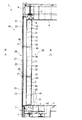
図1は、本実施形態に係るカーテンウォール10の外観姿図である。図2は、カーテンウォール10の縦断面図、図3は、カーテンウォール10の横断面図である。すなわち、図2は、図1に示す矢視II−II線断面図であり、図3は、図1に示す矢視III−III線断面図である。
【0022】
図1ないし図3において、建物1の外壁面は、柱2および梁3に沿って配置されたPC版4と、これらのPC版4で左右および上方の三方を囲まれたカーテンウォール10とによって、外観フラットに形成されている。PC版4は、プレキャストコンクリート製の外壁部材で、柱2や梁3の室外側側面に図示しないファスナーやブラケット等を介して取り付けられている。
建物1においてカーテンウォール10の室内側は2層分あるいは3層分の吹き抜け空間とされ、カーテンウォール10は、この吹き抜け空間の床5から天井6まで至る高さ寸法を有した開口部に設けられている。
【0023】
カーテンウォール10は、建物1の開口部における室内外の空間を仕切る壁体としての窓20と、この窓20の室内側に配置され窓20を室内外方向に関して支持する壁体支持構造体としての支持体30と、これらの窓20および支持体30を連結する連結部材40とを備えて構成されている。
【0024】
窓20は、それぞれアルミの押出形材製で、縦方向に延びる方立21および水平方向に延びる無目22を格子状に組み合せ、この格子状の各枠内に正面矩形状のガラスパネル23を嵌め込んで構成されている。そして、この窓20は、図示しないファスナーやブラケットを介して梁3に支持されるとともに、三方を囲むPC版4と図示しない防水材や気密材を介して接続されている。
なお、窓20の下側は、下側の梁3の室外側面を覆うスパンドレル7とされており、このスパンドレル7には窓20の方立21が延長され、窓20のガラスパネル23と外観同様のパネル材が嵌め込まれている。
【0025】
支持体30は、窓20の方立21に対応して各々の室内側に配置され、具体的には、図3に示すように、開口部の水平方向距離を略7等分した位置のうち、両端部を除く6箇所に配置されている。支持体30の上下端は、図2に示すように、それぞれファスナー8やブラケット等を介して上下の梁3に固定されている。これら上下の固定部は、それぞれ天井6や床5によって覆われており、室内からは見えなくなっている。特に、下端側の固定部は、ピット状に形成した床スラブ5Aと床5との隙間に設けられ、床5の上側に現れないようになっている。
【0026】
また、支持体30は、上下方向に延びて室内外方向に対向する一対の枠材31と、これらの枠材31の間に配置され枠材31同士を連結するパネル材としてのガラスパネル32とを備えて構成されている。
これらの枠材31およびガラスパネル32は、それぞれ支持体30の高さ寸法を略3等分した位置、すなわち、窓20の無目22に対応する高さ位置において上下に分割されている。そして、この分割位置には、後述する接合部材33が設けられ、この接合部材33を介して上下の枠材31およびガラスパネル32が一体に接合されている。また、支持体30の上下端側にも、ファスナー8に固定されるブラケットと枠材31およびガラスパネル32とを接合する接合部材33が設けられている。
枠材31とガラスパネル32とは、接合部材33および上下の接合部材33間の枠材31に沿って2箇所ずつ設けられた結合部材34を介して互いに結合されている。
【0027】
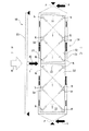
支持体30の枠材31およびガラスパネル32が上下に分割された位置には、図3に示すように、隣り合う支持体30同士あるいは支持体30と柱2に固定されたブラケット9とを水平方向に連結する水平ガラスパネル45が固定されている。すなわち、窓20の室内側において、支持体30および水平ガラスパネル45が、方立21および無目22と対応した格子状に組み合わされていることになる。
なお、水平ガラスパネル45は、平面矩形状の合わせガラスから形成されており、支持体30に対する座屈止め部材として機能する。
【0028】
連結部材40は、窓20の方立21および無目22が交差する位置、すなわち、支持体30の枠材31およびガラスパネル32が上下に分割された位置において、窓20と支持体30とを連結している。この連結部材40は、断面略矩形状をしたアルミの押出形材製で、室内外方向に延び、室外側の端部が方立21および無目22の交差位置に固定され、室内側の端部が支持体30の室外側の枠材31に固定されている。
【0029】
以下には、図4ないし図6に基づいて、カーテンウォール10の支持体30の構造について詳説する。
図4は、本実施形態に係る壁体支持構造体としての支持体30の要部を示す横断面図であり、図5は、支持体30の要部を示す縦断面図である。すなわち、図5は、図4に示す矢視V−V線断面図である。また、図6は、支持体30の要部を示す分解斜視図である。
【0030】
支持体30は、図4に示すように、一方の枠材31を窓20と対向させて、すなわち、窓20に略直交する方向にガラスパネル32の面内方向を合わせて設置されている。
支持体30の室内外方向両端に設けられる一対の枠材31は、それぞれ断面略凸字形に形成されたアルミの押出形材製で、凸状に突出した突出部31Aが互いに向き合うようにして対向配置されている。
なお、枠材31の材料としては、アルミに限らず、ステンレスや鉄等の金属材料が採用できる。
【0031】
ガラスパネル32は、枠材31の突出部31Aを挟んで2枚配置され、それぞれが室内外方向に延びて一対の枠材31同士を連結している。ガラスパネル32は、合わせガラスであり、2枚の単板ガラスの間にフィルムを挟んで一体に接着形成されたものである。
なお、パネル材としてのガラスパネル32は、合わせガラスに限らず、単板ガラスや強化ガラスでもよく、また、2枚配置することに限らず1枚あるいは3枚以上配置してもよい。また、パネル材としては、ガラスパネル32に限らず、アクリル板やポリカーボネート板等の透明材料が採用できる。
【0032】
支持体30の高さ寸法を略3等分した位置に設けられた接合部材33は、図5に示すように、略H字形の側面形状で枠材31の突出部31Aと略同一の厚さ寸法を有した鋼製板材から形成されている。そして、接合部材33は、一対の枠材31間に渡って、かつ、上下に分割された枠材31およびガラスパネル32に跨って配置されている。
接合部材33の両端部側で枠材31近傍の4箇所には、ボルト挿通孔33Bが設けられた結合部33Aが形成されており、両端部には、板厚寸法が薄くされた突片33Cと、ねじ孔33Dが形成されている。この突片33Cを枠材31の突出部31Aに挿入し、突出部31Aの側面からねじ孔33Dを通してボルト締めすることで、接合部材33が枠材31に固定されるとともに、上下の枠材31が接合される。
【0033】
上下の接合部材33間の枠材31に沿って2箇所ずつ設けられた結合部材34は、鋼製板材から形成され、一端側にボルト挿通孔34Aが設けられ、他端側にねじ孔34Bが設けられている。結合部材34の他端側は、接合部材33の突片33Cと同様に板厚寸法が薄くなっており、この他端側を枠材31の突出部31Aに挿入し、ねじ孔34Bを通してボルト締めすることで、結合部材34が枠材31に固定される。
【0034】
ガラスパネル32には、接合部材33および結合部材34のボルト挿通孔33B,34Aの位置に対応して、ボルト挿通孔32Aが設けられている。これらのボルト挿通孔32A,33B,34Aを通して、ボルト35およびナット36を螺合することによって、ガラスパネル32が接合部材33あるいは結合部材34を介して枠材31に結合される。
従って、これらの枠材31に固定された接合部材33および結合部材34と、これらに設けられたボルト挿通孔33B,34Aと、ガラスパネル32に設けられたボルト挿通孔32Aと、ボルト35およびナット36とによって、枠材31とガラスパネル32とを結合する結合手段が構成されることとなる。
【0035】
また、本実施形態では、枠材31とガラスパネル32とを結合するボルト35およびナット36によって、水平ガラスパネル45を支持体30に固定する構成となっている。
すなわち、ボルト35およびナット36によって、ブラケット46がガラスパネル32に固定されている。そして、このブラケット46を介して水平ガラスパネル45の図示しないボルト挿通孔を通して、ボルト47およびナット48を螺合することで、水平ガラスパネル45が支持体30に固定される。
【0036】
次に、図7に基づいて、カーテンウォール10に風圧力Wが作用した際の支持体30における支持機構について説明する。
図7は、本実施形態に係る壁体支持構造体としての支持体30の作用を示す概略側面図である。なお、図7に示すカーテンウォール10は、支持体30の支持機構を概念的に表したもので、各部の形状や寸法、部材構成等を簡略化あるいは省略している。
【0037】
図7において、カーテンウォール10の窓20に室外側から風圧力Wが作用した際、上下が建物1への固定部である支持点Pによって支持された支持体30には、連結部材40を介して外力Fが作用する。外力Fが作用した支持体30には、曲げモーメントおよびせん断力が生じ、支持体30の固定された上下の支持点Pには、それぞれ外力Fと釣り合う反力Rが生じる。支持体30の曲げモーメントおよびせん断力は、それぞれ支持体30を構成する枠材31およびガラスパネル32に生じる個材の応力として、これらを互いに結合する接合部材33および結合部材34を介して、すなわち、図7中符号Nで表す節点を介して伝達されることになる。
【0038】
枠材31には、支持体30に生じる曲げモーメントとしての引張り力および圧縮力(図7中黒塗り矢印で示す)が、それぞれ室内側の枠材31および室外側の枠材31に生じる。これらの引張り力および圧縮力は、外力Fが作用する支持体30の高さ方向中央付近で最大になり、上下の支持点Pに近づくに従って小さくなっていく応力である。
ガラスパネル32には、支持体30に生じるせん断力としての面内応力が生じるが、この面内応力は、各節点N間を結ぶ仮想のトラス斜材Tに沿った引張り力および圧縮力(図7中白抜き矢印で示す)と考えられる。これらの引張り力および圧縮力のうち、室内外方向の分力と外力Fとが釣り合い、上下方向の分力と枠材31の応力とが釣り合っていることになる。
【0039】
従って、支持体30に作用した外力Fは、各節点Nを介して枠材31およびガラスパネル32に伝わり、それぞれの部材に生じる応力として釣り合いを保ちながら支持点Pまで伝達されることとなる。
以上のように、支持体30の枠材31およびガラスパネル32が外力Fを伝達する支持機構を構成することで、カーテンウォール10の窓20に作用した風圧力Wは、支持体30によって建物1まで伝達され、窓20が確実に支持される。
【0040】
このような本実施形態によれば、以下のような効果がある。
(1) カーテンウォール10の窓20を支持する支持体30を一対の枠材31と、それらを連結するガラスパネル32とで構成したことにより、これらの枠材31およびガラスパネル32がトラス構造における弦材および斜材と同様に機能し、窓20から作用する外力Fを確実に建物1まで伝達して窓20を支持できる。従って、枠材31の断面積およびガラスパネル32の厚さ寸法を、それぞれ適切に設定することによって、必要とされる支持強度を効率よく得ることができ、支持体30の支持強度を容易に高めることができる。
【0041】
(2) 支持体30の上下端をファスナー8やブラケットを介して建物1に固定するだけで支持体30の施工ができるため、従来のテンショントラス構造における張力導入作業等の施工効率を低下させる作業を不要にでき、効率的に施工できる。
【0042】
(3) 窓20が支持体30によって室内外方向に関して支持されることにより、窓20の窓面に大きな支持構造を設ける必要がなく、窓20を構成する方立21や無目22等の構造材を小さくすることができるので、窓20の外観を軽快にし、開放感や意匠性を向上できる。
【0043】
(4) 支持体30を透明材料としてのガラスパネル32を備えた構成とすることにより、窓20から入射する外光を遮ることなく、室内まで導き入れることができるとともに、室内側から外の景色を見る視界を遮らないので、明るく開放的な壁面を形成することができる。
【0044】
(5) 支持体30の枠材31を金属材料としてのアルミから形成することにより、ガラスパネル32の寸法や材質とは無関係に枠材31の寸法や材質を設定でき、枠材31の断面積を大きくするだけで支持強度を高められる等、必要に応じた支持強度の設定が容易にできる。
【0045】
(6) 枠材31とガラスパネル32とを接合部材33の結合部33Aおよび結合部材34の位置のみで結合することにより、結合箇所を限定できるので、枠材31に沿った全長について連続的に結合する必要がなく、結合に要するブラケットやボルト35、ナット36等の部品点数を削減できるとともに、結合に係る作業手間を軽減できる。また、枠材31に結合されたガラスパネル32の面内に仮想のトラス斜材Tが構成され、結合箇所間にガラスパネル32を通して圧縮力および引張り力が伝達されることにより、枠材31およびガラスパネル32で構成された支持体30をトラス構造として有効に機能させることができる。
【0046】
(7) 枠材31およびガラスパネル32の結合手段として、枠材31に固定した接合部材33および結合部材34と、これらに設けたボルト挿通孔33B,34Aと、ガラスパネル32に設けたボルト挿通孔32Aと、ボルト35およびナット36とで構成することによって、ボルト35およびナット36を螺合するだけで結合作業を簡単に行うことができ、作業効率を向上できる。
【0047】
(8) 枠材31およびガラスパネル32をそれぞれ支持体30の高さ寸法を略3等分した位置で上下に分割し、これらを接合部材33を介して一体に接合して支持体30を構成することにより、枠材31およびガラスパネル32を製作や運搬の効率に優れた大きさで製作し、運搬した後に組み立てることで、高さ寸法の大きい支持体30を容易に形成することができ、製作や運搬に要する費用を低減し手間を軽減することができる。
【0048】
〔第2実施形態〕
図8は、第2実施形態に係る壁体支持構造体としての支持体50を示す概略側面図である。
第2実施形態に係る支持体50は、枠材31に対する結合部材34の固定位置が、前述の第1実施形態の場合と異なるもので、その他の構成は第1実施形態と同様である。従って、第1実施形態と異なる構成要件について、以下に説明する。
【0049】
図8において、上下の接合部材33間の枠材31に沿って設けられる結合部材34は、図8中左側(室外側)の枠材31に対して2箇所、図8中右側(室内側)の枠材31に対して1箇所にそれぞれ固定されている。すなわち、一対の枠材31に対して上下方向に交互になるように結合部材34が設けられ、これらの結合部材34同士および結合部材と接合部材33とを結ぶガラスパネル32面内の仮想のトラス斜材T同士が交差しない構成となっている。
【0050】
このような支持体50では、連結部材40を介して図示しない窓から作用する外力が接合部材33から室内外の枠材31およびガラスパネル32に伝達される。そして、ガラスパネル32には、仮想のトラス斜材Tに沿った引張り力または圧縮力が生じて、図示しない支持点まで力が伝達されることになる。
【0051】
このような本実施形態によれば、前述の効果に加えて、次のような効果がある。
(9) 結合部材34の固定位置を室内外の枠材31に対してそれぞれ上下方向に異なる位置とすることにより、結合部材34の固定位置の設定についてデザインの自由度を高めることができるとともに、必要とされる支持強度に応じて適宜結合部材34の数を減らすことができるので、部品点数および結合作業手間をさらに低減することができる。
【0052】
なお、本発明は、前記実施形態に限定されるものではない。
例えば、前記実施形態では、壁体支持構造体としての支持体30が建物1の外壁面を構成するカーテンウォール10の窓20を支持するものとしたが、これに限らず、建物の室内における間仕切壁や装飾用の壁等を支持する壁体支持構造体として適用できる。
このような間仕切壁等に本発明の壁体支持構造体を適用すれば、例えば、間仕切壁に照明を埋め込んだり、壁面に絵画や彫刻等の装飾を施した場合に、これらの照明や装飾が壁体支持構造体のガラスパネルを通して認識できるので、空間の利用者が窮屈さを感じず、壁面の広がりを演出して建物空間の快適性を向上できる。
【0053】
また、前記実施形態では、支持体30のパネル材として透明材料からなるガラスパネル32を採用したが、これに限らず、不透明材料や半透明材料からなるパネル材を採用できる。
不透明材料からなるパネル材としては、金属製や合成樹脂製のカラーパネル等が採用でき、さらに、これらのパネル材に多数の孔を開けたり、メッシュ状や格子状に加工して光が透過するようにしたものでもよい。また、半透明材料からなるパネル材としては、すりガラスや型板ガラス等が採用できる。
壁体支持構造体に不透明材料や半透明材料からなるパネル材を採用することにより、デザイン性に富んだ各種の材料を利用でき、壁面のデザインの自由度を高めて意匠性を向上できる。
【0054】
前記実施形態では、枠材31とガラスパネル32とを接合部材33の結合部33Aおよび結合部材34の位置のみで結合したが、これに限らず、枠材に沿って連続的に枠材およびパネル材を結合してもよい。このようにすることで、枠材とパネル材との結合強度を高め、壁体支持構造体の支持強度を高めることができる。
また、前記実施形態では、枠材31およびガラスパネル32をそれぞれ支持体30の高さ寸法を略3等分した位置で上下に分割し、これらを接合部材33を介して一体に接合して支持体30を構成したが、これに限らず、壁体支持構造体の高さと略同一の高さ寸法を有する枠材およびパネル材によって壁体支持構造体を構成してもよい。このようにすることで、接合部材が不要になり、部品点数を低減し接合に掛かる作業手間を軽減できる。
【0055】
前記実施形態では、カーテンウォール10の窓20を方立21、無目22およびガラスパネル23によって構成したが、これに限らず、方立や無目を省略し、DPG方式によりガラスパネルを支持する構成としてもよい。この際、DPG方式に用いられる正面略X字形状等の支持具を連結部材を介して壁体支持構造体に連結することで、壁体支持構造体によって窓を支持することができる。このようにすることで、窓面の開放感をより高めることができるとともに、窓面の外観の意匠性をより向上できる。
【0056】
【発明の効果】
以上に述べたように、本発明の壁体支持構造体およびカーテンウォールによれば、壁面の開放感や意匠性を高めつつ、効率よく施工でき、かつ、容易に支持強度を高めることができるという効果がある。
【図面の簡単な説明】
【図1】本発明の第1実施形態に係るカーテンウォールの外観姿図である。
【図2】前記実施形態に係るカーテンウォールの縦断面図であり、図1のII−II線断面図である。
【図3】前記実施形態に係るカーテンウォールの横断面図であり、図1のIII−III線断面図である。
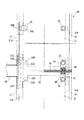
【図4】前記実施形態に係る壁体支持構造体の要部を示す横断面図である。
【図5】前記実施形態に係る壁体支持構造体の要部を示す縦断面図であり、図4のV−V線断面図である。
【図6】前記実施形態に係る壁体支持構造体の要部を示す分解斜視図である。
【図7】前記実施形態に係る壁体支持構造体の作用を示す概略側面図である。
【図8】本発明の第2実施形態に係る壁体支持構造体を示す概略側面図である。
【符号の説明】
1…建物、10…カーテンウォール、20…壁体である窓、30,50…壁体支持構造体である支持体、31…枠材、32…パネル材であるガラスパネル、33…接続部材、34…結合部材、35…ボルト、36…ナット、40…連結部材。[0001]
TECHNICAL FIELD OF THE INVENTION
The present invention relates to a wall support structure and a curtain wall.
[0002]
[Background Art]
In buildings and the like in recent years, various designs have come to be used for the outer wall surface of the curtain wall. In particular, curtain walls used as outer walls such as stairwells in large buildings are made of glass for the majority of the outer wall, and the cubic and blind lines supporting this glass are made as thin as possible or eliminated. Those with enhanced openness and design are often used.
As such a curtain wall, for example, a glass curtain wall in which glass is supported by a DPG (dot point glazing) method is known. In this DPG method, four through-holes formed at the corners of four glass panels adjacent to each other are supported by supports such as a substantially X-shaped front face, so that a square or a blind can be omitted. Since the structural material is inconspicuous, the open feeling and design of the outer wall surface can be enhanced.
[0003]
On the other hand, such a curtain wall is often large in both width and height, and when wind pressure acts on the outer wall surface, a very large force acts in the indoor and outdoor directions of the curtain wall. Therefore, a support structure that can withstand this force is required.
As such a supporting structure, a steel mullion in which steel members whose upper and lower ends are fixed to a building skeleton are arranged along the wall on the indoor side of the wall constituting the outer wall surface and the wall is connected to the steel member. A form of support structure is common. In this steel frame mullion type support structure, a steel frame member such as an H-beam or a C-beam is disposed so that the back of the member is aligned with the interior and exterior directions.
Therefore, even if the above-mentioned wind pressure acts, the wall body can be reliably supported in the back direction of the member having high strength and rigidity. Furthermore, since the apparent size of the steel frame member in the front direction of the outer wall surface is the size in the width direction, the steel frame member can be made inconspicuous.
[0004]
As a support structure different from the steel mullion type, a truss mullion type support structure in which a truss structure configured by combining chords and diagonal members in a truss shape is arranged along a wall is known (for example, And Patent Document 1).
In such a truss marion type support structure, a predetermined support strength can be obtained with a small amount of steel material as compared with the above-described steel members such as the H-shaped steel and the C-shaped steel, so that the cost can be reduced and the appearance is lightened. There is a merit that can be shown.
[0005]
However, in any of the above-described steel frame mullion type and truss mullion type support structures, the steel frame members themselves, the diagonal members of the truss structure, and the like obstruct the view in the direction inclined with respect to the outer wall surface. Therefore, despite the fact that the structural material on the outer wall surface was made inconspicuous and the sense of openness was enhanced, the effect of the arrangement of the support structure was diminished, and sufficient openness was not obtained, and the design was also reduced. There is an inconvenience of doing so.
[0006]
As a support structure devised to solve such inconveniences, a tension truss type support structure (for example, see Patent Document 2) configured by combining a tension member or a bundle material into which tension is introduced, or a wall member There is a glass mullion type support structure (for example, refer to Patent Document 3) which is configured by rib plate glass arranged along a direction intersecting the wall surface.
[0007]
The tension truss type support structure of
[0008]
Patent Literature 3 discloses a glass mullion type support structure in which a rib plate glass disposed along a room side of a face plate glass, which is a wall, in a direction intersecting with a wall surface, passes through a gripping member that grips the rib plate glass. It is configured to be connected to. Therefore, since the supporting structure other than the holding member and the connecting portion with the wall is formed of glass, it does not obstruct the external light transmitted through the face plate glass and the view of a person from inside and outside the room, and is bright and open. A curtain wall having excellent design properties can be formed.
[0009]
[Patent Document 1]
JP-A-9-242234
[Patent Document 2]
JP-A-2000-303598
[Patent Document 3]
JP-A-10-231571
[0010]
[Problems to be solved by the invention]
Meanwhile, in the tension truss type support structure of
Therefore, there is a problem that the efficiency of construction cannot be sufficiently improved with the tension truss type support structure.
[0011]
In the glass mullion type support structure of Patent Document 3 described above, when wind pressure acts on the wall surface, only the rib plate glass supporting the face plate glass must withstand the wind pressure. Therefore, when high supporting strength is required to support the wall of the large atrium, it is necessary to increase the thickness and expected dimensions of the rib sheet glass or use a high-strength material such as tempered glass. Support strength must be increased.
However, in order to increase the supporting strength by such a method, the thickness of the rib sheet glass becomes extremely large, the room size is increased by increasing the expected size, and the cost increases due to the high strength material. Therefore, there is a problem that the supporting strength cannot be easily increased.
[0012]
An object of the present invention is to provide a wall support structure and a curtain wall that can be efficiently constructed while enhancing the feeling of opening and design of the wall surface, and can easily increase the support strength.
[0013]
[Means for Solving the Problems]
A wall supporting structure of the present invention is a wall supporting structure fixed to a building and supporting a wall constituting a wall surface of the building, wherein a pair of frame members arranged to face each other, and these frame members And a panel member that connects the pair of frame members to each other, and the wall is disposed on one side of the pair of frame members.
[0014]
In such a configuration, the supporting structure is composed of a pair of frame members and a panel member connecting them, so that these frame members and panel members function in the same manner as chord members and diagonal members in the truss structure. In addition, the wall can be supported by reliably transmitting the force acting from the wall to the building. Therefore, by appropriately setting the cross-sectional area of the frame member and the thickness dimension of the panel member, the required supporting strength can be efficiently obtained, and the supporting strength can be easily increased.
Further, in such a support structure, for example, since the work can be performed simply by fixing both ends of the support structure to the building, it is not necessary to perform the work of reducing the work efficiency such as the work of introducing the tension in the above-described tension truss structure. Thus, the efficiency of construction can be improved.
And by such a support structure, the structural material such as the cubic or blinds constituting the wall can be reduced or eliminated, the appearance of the wall can be reduced, and the feeling of opening and the design can be improved. .
[0015]
Further, the panel material connecting the frame members is formed as a separate member from the frame material, so that the material and characteristics of the panel material can be arbitrarily selected.
For example, by forming the panel material from a material having light transmittance, if the wall is a window that constitutes the outer wall surface of the building, it can be guided into the room without blocking external light incident from this window. And a bright and open wall surface can be formed. In addition, even if the wall is other than a window, if the lighting is embedded in the wall or a decoration such as a painting or a sculpture is applied to the surface of the wall, these lights and decorations can be recognized through the panel body. The user can feel the crampedness and direct the expansion of the wall to improve the comfort of the building space.
Furthermore, by forming the panel material from a color panel, a translucent material, or the like, it is not necessary to use a separate finishing material, so that the degree of freedom in designing the wall surface can be increased and the design can be improved.
[0016]
Further, in the wall supporting structure of the present invention, it is preferable that the pair of frame members and the panel member are joined by joining means provided at a plurality of positions along the frame members.
In such a configuration, connecting means for connecting the frame material and the panel material are provided at a plurality of locations along the frame material, and are connected only at these connection locations, so that the entirety along the frame material is continuously provided. There is no need to join the panel members, and the joining points can be limited.
That is, as a method of joining the frame member and the panel member, there are a method of continuously bonding along the frame member and a method of screwing at a predetermined pitch. However, these methods have a disadvantage that the material and labor required for the connection are increased.
Therefore, by restricting the connecting portions, the above-mentioned inconvenience can be solved, and the number of components such as brackets, bolts, nuts, etc., for connecting the frame member and the panel member can be reduced, and the labor involved in the connection can be reduced.
Further, a virtual diagonal member is formed in the plane of the panel member joined to the frame member, that is, the compressive force and the tensile force are transmitted through the panel member between the joining points of the pair of frame members, The support structure composed of the frame material and the panel material can function effectively as a truss structure.
[0017]
In the wall support structure of the present invention, it is preferable that the panel member is formed of a light-transmitting material.
Here, as a panel material formed of a light-transmitting material, a panel material made of a highly transparent material such as glass, acrylic, or polycarbonate, an aluminum panel, a stainless steel plate, or the like, through which many holes are formed to transmit light. It is possible to employ a plate member made of a metal material or a plate member formed by processing a metal material into a mesh shape or a lattice shape.
In such a configuration, by forming the panel material disposed along the wall surface from a light-transmitting material, a bright and open wall surface can be formed without obstruction of light and view by the panel material, and the wall surface can be formed. The spaciousness can be produced to improve the comfort of the building space.
[0018]
Further, in the wall support structure of the present invention, it is preferable that the pair of frame members is formed of a metal material, and the panel member is formed of a transparent material.
Here, as the metal material, aluminum, stainless steel, iron, or the like can be adopted, and these metal materials may be appropriately combined. Further, as the transparent material, glass, acrylic, polycarbonate, etc. can be adopted, and even if these materials are colored or patterned, various coatings, films, wire mesh, etc., the opposite side is passed through the material. Any object that can recognize the shape, shape, color, etc. of the person or object can be applied.
In such a configuration, the frame material is formed of a metal material and the panel material is formed of a transparent material, that is, the frame material and the panel material are formed of different materials, respectively, so that they are independent of the dimensions and materials of the panel material. The size and material of the frame material can be set, and the support strength can be easily set as needed, for example, the support strength can be increased simply by increasing the cross-sectional area of the frame material.
Further, by forming the panel material from a transparent material, the panel material can be made less noticeable, and the sense of opening of the wall surface can be further enhanced.
[0019]
On the other hand, the curtain wall of the present invention connects any of the wall support structures described above, a wall supported by the wall support structure, and the wall support structure and the wall. It is characterized by including a connecting member, and by providing such a wall supporting structure, the above-described operation and effect are obtained, and the object of the present invention is achieved.
[0020]
BEST MODE FOR CARRYING OUT THE INVENTION
Hereinafter, embodiments of the present invention will be described with reference to the drawings.
In the second and subsequent embodiments, the same components as those described in the following first embodiment and components having the same functions are denoted by the same reference numerals as those in the first embodiment. Their description is omitted or simplified.
[0021]
[First Embodiment]
FIG. 1 is an external view of a
[0022]
1 to 3, the outer wall surface of the building 1 is composed of a
In the building 1, the interior side of the
[0023]
The
[0024]
Each of the
The lower side of the
[0025]
The
[0026]
The
The
The
[0027]
At positions where the
Note that the
[0028]
The connecting
[0029]
Hereinafter, the structure of the
FIG. 4 is a cross-sectional view showing a main part of a
[0030]
As shown in FIG. 4, the
A pair of
The material of the
[0031]
Two
In addition, the
[0032]
As shown in FIG. 5, the joining
At four locations near the
[0033]
The joining
[0034]
The
Accordingly, the joining
[0035]
Further, in the present embodiment, the
That is, the
[0036]
Next, a support mechanism of the
FIG. 7 is a schematic side view showing the operation of the
[0037]
In FIG. 7, when wind pressure W acts on the
[0038]
In the
In the
[0039]
Accordingly, the external force F acting on the
As described above, since the
[0040]
According to this embodiment, the following effects can be obtained.
(1) Since the
[0041]
(2) Since the
[0042]
(3) Since the
[0043]
(4) Since the
[0044]
(5) By forming the
[0045]
(6) By joining the
[0046]
(7) As joining means of the
[0047]
(8) The
[0048]
[Second embodiment]
FIG. 8 is a schematic side view showing a
The
[0049]
8, two connecting
[0050]
In such a
[0051]
According to the present embodiment, the following effects are obtained in addition to the effects described above.
(9) By setting the fixing position of the
[0052]
Note that the present invention is not limited to the above embodiment.
For example, in the above embodiment, the
If the wall support structure of the present invention is applied to such a partition wall or the like, for example, when lighting is embedded in the partition wall or when decoration such as painting or sculpture is applied to the wall surface, these lighting and decoration are applied. Since it can be recognized through the glass panel of the wall support structure, the user of the space does not feel cramped and directs the expansion of the wall surface to improve the comfort of the building space.
[0053]
In the above-described embodiment, the
As a panel material made of an opaque material, a metal or synthetic resin color panel can be adopted, and furthermore, a large number of holes are formed in these panel materials, or the panel material is processed into a mesh shape or a lattice shape to transmit light. Such a configuration may be used. Further, as the panel material made of a translucent material, frosted glass, template glass, or the like can be employed.
By adopting a panel material made of an opaque material or a translucent material for the wall support structure, various materials having a high design property can be used, and the degree of freedom in the design of the wall surface can be increased to improve the design.
[0054]
In the above-described embodiment, the
Further, in the above-described embodiment, the
[0055]
In the above-described embodiment, the
[0056]
【The invention's effect】
As described above, according to the wall support structure and the curtain wall of the present invention, it is possible to efficiently construct and improve the support strength easily while improving the open feeling and design of the wall. effective.
[Brief description of the drawings]
FIG. 1 is an external view of a curtain wall according to a first embodiment of the present invention.
FIG. 2 is a longitudinal sectional view of the curtain wall according to the embodiment, and is a sectional view taken along line II-II of FIG.
FIG. 3 is a cross-sectional view of the curtain wall according to the embodiment, and is a cross-sectional view taken along line III-III of FIG.
FIG. 4 is a cross-sectional view showing a main part of the wall support structure according to the embodiment.
FIG. 5 is a longitudinal sectional view showing a main part of the wall supporting structure according to the embodiment, and is a sectional view taken along line VV of FIG. 4;
FIG. 6 is an exploded perspective view showing a main part of the wall support structure according to the embodiment.
FIG. 7 is a schematic side view showing the operation of the wall support structure according to the embodiment.
FIG. 8 is a schematic side view showing a wall supporting structure according to a second embodiment of the present invention.
[Explanation of symbols]
DESCRIPTION OF SYMBOLS 1 ... Building, 10 ... Curtain wall, 20 ... Window which is a wall, 30, 50 ... Support which is a wall support structure, 31 ... Frame material, 32 ... Glass panel which is a panel material, 33 ... Connection member, 34: connecting member, 35: bolt, 36: nut, 40: connecting member.
Claims (5)
対向配置される一対の枠材と、これらの枠材とは別部材からなり当該一対の枠材間を連結するパネル材とを備えて構成され、
前記一対の枠材のうちの一方側に前記壁体が配置された壁体支持構造体。A wall support structure fixed to the building and supporting a wall constituting the wall surface of the building,
It comprises a pair of frame members arranged opposite to each other, and a panel member made of a separate member and connecting the pair of frame members,
A wall support structure in which the wall is disposed on one side of the pair of frame members.
Priority Applications (1)
| Application Number | Priority Date | Filing Date | Title |
|---|---|---|---|
| JP2002302557A JP3953403B2 (en) | 2002-10-17 | 2002-10-17 | Wall support structure and curtain wall |
Applications Claiming Priority (1)
| Application Number | Priority Date | Filing Date | Title |
|---|---|---|---|
| JP2002302557A JP3953403B2 (en) | 2002-10-17 | 2002-10-17 | Wall support structure and curtain wall |
Publications (2)
| Publication Number | Publication Date |
|---|---|
| JP2004137731A true JP2004137731A (en) | 2004-05-13 |
| JP3953403B2 JP3953403B2 (en) | 2007-08-08 |
Family
ID=32450590
Family Applications (1)
| Application Number | Title | Priority Date | Filing Date |
|---|---|---|---|
| JP2002302557A Expired - Fee Related JP3953403B2 (en) | 2002-10-17 | 2002-10-17 | Wall support structure and curtain wall |
Country Status (1)
| Country | Link |
|---|---|
| JP (1) | JP3953403B2 (en) |
Cited By (4)
| Publication number | Priority date | Publication date | Assignee | Title |
|---|---|---|---|---|
| CN103282707A (en) * | 2010-11-05 | 2013-09-04 | 新日铁住金株式会社 | Tubular threaded joint having improved high torque performance |
| JP2021050549A (en) * | 2019-09-25 | 2021-04-01 | 旭化成ホームズ株式会社 | building |
| CN115839142A (en) * | 2022-12-08 | 2023-03-24 | 广州江河幕墙系统工程有限公司 | Construction method of external inclined long-span cable curtain wall |
| US20240068230A1 (en) * | 2022-08-26 | 2024-02-29 | Jesse James LEWIN | Separation panels in food production |
Families Citing this family (1)
| Publication number | Priority date | Publication date | Assignee | Title |
|---|---|---|---|---|
| CN111364773B (en) * | 2020-03-06 | 2022-03-29 | 北京城建集团有限责任公司 | Curtain wall stay cable tensioning method and curtain wall mounting structure |
-
2002
- 2002-10-17 JP JP2002302557A patent/JP3953403B2/en not_active Expired - Fee Related
Cited By (7)
| Publication number | Priority date | Publication date | Assignee | Title |
|---|---|---|---|---|
| CN103282707A (en) * | 2010-11-05 | 2013-09-04 | 新日铁住金株式会社 | Tubular threaded joint having improved high torque performance |
| CN103282707B (en) * | 2010-11-05 | 2015-04-29 | 新日铁住金株式会社 | Tubular threaded joint having improved high torque performance |
| JP2021050549A (en) * | 2019-09-25 | 2021-04-01 | 旭化成ホームズ株式会社 | building |
| JP7421890B2 (en) | 2019-09-25 | 2024-01-25 | 旭化成ホームズ株式会社 | building |
| US20240068230A1 (en) * | 2022-08-26 | 2024-02-29 | Jesse James LEWIN | Separation panels in food production |
| US12134891B2 (en) * | 2022-08-26 | 2024-11-05 | Jesse James LEWIN | Separation panels in food production |
| CN115839142A (en) * | 2022-12-08 | 2023-03-24 | 广州江河幕墙系统工程有限公司 | Construction method of external inclined long-span cable curtain wall |
Also Published As
| Publication number | Publication date |
|---|---|
| JP3953403B2 (en) | 2007-08-08 |
Similar Documents
| Publication | Publication Date | Title |
|---|---|---|
| JP3953403B2 (en) | Wall support structure and curtain wall | |
| JPH04108966A (en) | Assembly type damping wall | |
| RU46283U1 (en) | PROFILE CONSTRUCTION, LIGHT-TRANSPARENT WALL WITH SUCH PROFILE AND QUICK-CONNECTED STRUCTURE WITH LIGHT-TRANSPARENT WALLS | |
| JP3694473B2 (en) | Wall with opening | |
| JP4465086B2 (en) | Building | |
| JP7638114B2 (en) | Partitions and partition structure | |
| KR200413016Y1 (en) | Rib glass and patch type glass structure composed of homogeneous glass | |
| JPH03199550A (en) | Proof stress panel for construction and construction frame-work structure | |
| JP7190371B2 (en) | building | |
| JP3435361B2 (en) | Fuller dome type simple building | |
| JP4355244B2 (en) | building | |
| JP2024120803A (en) | Buildings and construction methods | |
| JP2000017763A (en) | Wall support device | |
| JPH0657854A (en) | Lightweight fire resistant sound insulating partitioning wall | |
| JP2007332644A (en) | Wall structure of glass panel, glass panel unit and curtain wall | |
| JPH1136490A (en) | Architectural panel, partition wall structure using the same, and wall construction method | |
| JPH08303127A (en) | Window structure | |
| JPH09144181A (en) | Curtain wall unit | |
| JP2004346638A (en) | curtain wall | |
| JPH10266334A (en) | Building construction panel combination and building construction method using the same | |
| KR19980010269U (en) | Tile panel structure for exterior wall construction of building | |
| JPH0978760A (en) | Connection structure of lattice material for truss | |
| JP2592863B2 (en) | Unit building | |
| JP3596470B2 (en) | Wall | |
| JPH08105154A (en) | Building material panel |
Legal Events
| Date | Code | Title | Description |
|---|---|---|---|
| A621 | Written request for application examination |
Free format text: JAPANESE INTERMEDIATE CODE: A621 Effective date: 20050218 |
|
| A977 | Report on retrieval |
Free format text: JAPANESE INTERMEDIATE CODE: A971007 Effective date: 20061108 |
|
| A131 | Notification of reasons for refusal |
Free format text: JAPANESE INTERMEDIATE CODE: A131 Effective date: 20061205 |
|
| A521 | Written amendment |
Free format text: JAPANESE INTERMEDIATE CODE: A523 Effective date: 20070201 |
|
| TRDD | Decision of grant or rejection written | ||
| A01 | Written decision to grant a patent or to grant a registration (utility model) |
Free format text: JAPANESE INTERMEDIATE CODE: A01 Effective date: 20070403 |
|
| A61 | First payment of annual fees (during grant procedure) |
Free format text: JAPANESE INTERMEDIATE CODE: A61 Effective date: 20070424 |
|
| R150 | Certificate of patent or registration of utility model |
Ref document number: 3953403 Country of ref document: JP Free format text: JAPANESE INTERMEDIATE CODE: R150 Free format text: JAPANESE INTERMEDIATE CODE: R150 |
|
| FPAY | Renewal fee payment (event date is renewal date of database) |
Free format text: PAYMENT UNTIL: 20100511 Year of fee payment: 3 |
|
| FPAY | Renewal fee payment (event date is renewal date of database) |
Free format text: PAYMENT UNTIL: 20110511 Year of fee payment: 4 |
|
| FPAY | Renewal fee payment (event date is renewal date of database) |
Free format text: PAYMENT UNTIL: 20120511 Year of fee payment: 5 |
|
| FPAY | Renewal fee payment (event date is renewal date of database) |
Free format text: PAYMENT UNTIL: 20130511 Year of fee payment: 6 |
|
| FPAY | Renewal fee payment (event date is renewal date of database) |
Free format text: PAYMENT UNTIL: 20140511 Year of fee payment: 7 |
|
| LAPS | Cancellation because of no payment of annual fees |