JP2004135904A - Rack device - Google Patents
Rack device Download PDFInfo
- Publication number
- JP2004135904A JP2004135904A JP2002304016A JP2002304016A JP2004135904A JP 2004135904 A JP2004135904 A JP 2004135904A JP 2002304016 A JP2002304016 A JP 2002304016A JP 2002304016 A JP2002304016 A JP 2002304016A JP 2004135904 A JP2004135904 A JP 2004135904A
- Authority
- JP
- Japan
- Prior art keywords
- shelf
- plate
- main
- auxiliary
- main shelf
- Prior art date
- Legal status (The legal status is an assumption and is not a legal conclusion. Google has not performed a legal analysis and makes no representation as to the accuracy of the status listed.)
- Granted
Links
Images


Landscapes
- Assembled Shelves (AREA)
Abstract
Description
【0001】
【発明の属する技術分野】
本発明は、多段式の棚装置に係り、より詳しくは、多数の電気製品を収納しながら充電できる配線を可能とする棚装置の構造に関するものである。
【0002】
【従来の技術】
従来、棚装置における棚板を、前半棚部に対して後半棚部を上側にする段違い状に形成したもの(特許文献1)や、上下に適宜間隔で配置された主棚板の各後半部(奥側)の上方に補助棚板を着脱可能に配置した棚装置(特許文献2)が公知である。
【0003】
【特許文献1】
実開平5−68336号公報(図1参照)
【特許文献2】
実開平5−9336号公報(図1参照)
【0004】
【発明が解決しようとする課題】
しかしながら、特許文献1の棚装置では、下側に配置した平板状の棚板の奥側の上方と、上側の段違い状の棚板における後半棚部の下方との上下空間を大きくできることにより、その部分に背の高い品物を配置でき、棚装置の収納スペースを有効に利用するものであるが、前記段違いの棚を上下に複数段に配置したときには、収納スペースの有効利用に寄与できないという問題があった。
【0005】
他方、特許文献2における構成では、棚装置の奥側に配置した補助棚板には背の低い品物を載置し、主棚板の前半部には背の高い品物を載置し、さらに、主棚板の後半部と補助棚板の下面との間には、一層背の低い品物を収納できるから、その点で収納スペースを有効利用できる。しかし、このような棚装置に多数の電気製品を載置し、そのうちの一部の電気製品に充電する場合、配線コードやコンセントが棚装置の前側から見えることになり、外観が悪くなるという問題があった。
【0006】
本発明は、棚装置の収納スペースを有効利用しながら、複数の電気製品に充電する場合の配線コードやコンセント等を棚装置の前から見えない位置に収納でき、外観のすっきりした棚装置を提供することを目的とするものである。
【0007】
【課題を解決するための手段】
前記目的を達成するため、請求項1に記載の発明の棚装置は、所定間隔を隔てて対向配置した一対の側板と、該一対の側板間に着脱自在、且つ高さ位置調節自在に配置した複数の主棚板と、該主棚板上の奥側に段差をつけた補助棚板とを有し、該補助棚板の前端から下向きに垂下する前板と前記主棚板の上面との間に配線隙間を設けたものである。
【0008】
請求項2に記載の発明は、請求項1に記載の棚装置において、前記主棚板上面と補助棚板の下面との間をコンセント等の電気部品の収納空間に形成したものである。
【0009】
請求項3に記載の発明は、請求項2に記載の棚装置において、前記一対の側板間に配置する背板と前記主棚板の後端との間に隙間を設け、該隙間には、上下方向に開口する通線カバー体を設けたものである。
【0010】
請求項4に記載の発明は、請求項1乃至3のいずれかに記載の棚装置において、前記一対の側板間の下部に配置した底カバー板の下方にコード受け樋を設けたものである。
【0011】
【発明の効果】
上記の請求項1に記載の発明によれば、主棚板上の奥側に段差をつけた補助棚板とを有するから、載置する電気製品の背の高さに応じて、補助棚板及び主棚板上の前側に載置できて収納効率を高めることができる。そして、補助棚板の前端から下向きに垂下する前板と前記主棚板の上面との間に配線隙間を設けたものであるから、長い配線コードの大部分を前記隙間を介して補助棚板の下方に配置てきるから棚装置の外観をすっきりさせることができるという効果を奏する。
【0012】
また、請求項2に記載の発明によれば、請求項1に記載の発明による効果に加えて、主棚板上面と補助棚板の下面との間をコンセント等の電気部品の収納空間に形成したものであるから、常時備えつけの電気部品を、一時的に保管する電気製品と別の区切られた収納空間に収納できる結果、一時的に保管する電気製品の整理整頓を実行し易くなるという効果を奏する。また、常時備えつけの電気部品を外側から見えない個所(収納空間)に配置できるから、棚装置の外観をすっきりさせることができるという効果を奏する。
【0013】
さらに、請求項3に記載の発明によれば、請求項2に記載の発明による効果に加えて、補助棚板の下方に配置した電気部品の配線コードを下方に挿通する個所を通線カバー体にて覆うことができ、この配線コードの乱雑さも見えなくして外観をすっきりさせることができる。
【0014】
請求項4に記載の発明によれば、棚装置の下部に設けたコード受け樋にて集まった配線コードの余長部や差込みコンセント等の電気部品を更に収納でき、配線作業、配線形態をすっきりさせることができる。また、配線コードの余長部が棚装置の下部前側にはみ出さず、足元の安全を確保できるという効果も奏する。
【0015】
【発明の実施の形態】
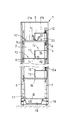
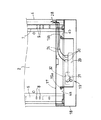
次に、本発明を具体化した実施形態について説明すると、図1は本発明の棚装置の正面図、図2は棚装置の横断面図、図3は要部を示す一部切欠き斜視図、図4は棚装置の下部の横断面図である。
【0016】
棚装置1は、適宜距離隔てて対向配置される左右一対の側板2、2と、天板3と底板4と、一対の側板2、2の背面を覆う背板5を有しこれらの部材にて枠状に形成されている。この棚装置1は断面横向きコ字状の枠型のベース18に載置され、ベース18の上面と前記底板4とを図示しないビスにて連結固定する。一対の側板2、2の相対向する内面には、その前後部位に、横断面が略コ字状で縦長の補強部材6、7が点溶接等により固定されている。各補強部材6、7には縦方向に適宜間隔にて係止孔8、9が穿設されている。
【0017】
複数の主棚板10は、それぞれ、前記任意高さ位置の係止孔8、9に着脱自在に係止する下向きの係合爪(図示せず)を有し、平面視略矩形状である。各主棚板10の平板状の載置板部10aの前後端部10b,10cは下向きに折り曲げた断面略コ字状に形成されている(図3参照)。また、主棚板10の載置板部10aの下面には、横長の補強片11が点溶接にて固定されている。
【0018】
そして、前記主棚板10の載置板部10aの上面のうち奥側(後半部寄り)には、背の低い補助棚板12が配置されている。この補助棚板12は、前記主棚板10の載置板部10aの奥行き寸法D1の略半分程度の奥行き寸法D2を有する横長の平坦な載置部12aと、該載置部12aの両端を下向きに屈曲させた左右両側の足板12b,12bと、載置部12aの前端から下向きに垂下する前板13とからなる。前記両足板12b,12bの下端(水平部)は前記主棚板10の載置板部10aにネジ止め(図示せず)にて連結しても良い。
【0019】
載置部12aの間口方向の寸法は載置板部10aの間口方向の寸法と略同じに設定しても良いし、載置板部10aの間口方向の寸法より短い載置部12aを有する複数の補助棚板12を横一列状に配置しても良い。足板12b,12bの高さ寸法H1に対して、前板13の高さ寸法を小さく設定し、且つ前板13の下端と主棚板10の載置板部10aの上面との間に、高さ寸法H2の横長の配線コード挿通用の隙間14を形成する。
【0020】
従って、主棚板10の載置板部10aの上面の奥側(後半寄り部位)と補助棚板12における載置部12aとの間には、前記隙間14に連通する物品収納空間15が形成されることになる。
【0021】
また、上下方向に適宜間隔にて配置された主棚板10の後端部と背板5との間には、断面略コ字状の通線カバー体16を配置し、通線カバー体16の左右両側の当接片16aを接着剤板5に対してマグネットテープまたは両面接着テープ等にて固定する(図3参照)。
【0022】
棚装置1の下端部であって、前記底板4における上側の前後水平枠板4a,4bには、上向きに着脱可能な底カバー板17が載置してあり、前後水平枠板4a,4に、横長のコード受け樋19の下向きコ字状の前後係止片19a,19bを係止している(図4参照)。従って、底カバー板17を外すと、コード受け樋19の上面が開放され、また、このコード受け樋19も着脱可能となる。
【0023】
上記のように構成された棚装置1において、図1〜図3に示すように、電気製品21、例えば、会社等において多数の作業者が使用する多数の携帯電話21aや携帯情報端末21bも携帯用プリンタ21cを、夜間等の不使用時に一時的に保管しながら一度に充電するため、主棚板10の載置板部10aの上面の奥側(後半寄り部位)と補助棚板12における載置部12aとの間の物品収納空間15内には、常備の電気部品としてのACアダプタ22(100V〜200V等の商用交流電源から所定の低い電圧(4.5V〜4.2V) の直流電気に変換するもの)や、前記商用交流電源からのコード24に接続した多連口の差込みコンセント23を複数配置し、ACアダプタ22の一方のコード(入力コード)25aに接続のソケット26を前記差込みコンセント23に接続しておき、ACアダプタ22の他方の出力コード25bを前記前板13の下端の隙間14から前方に延ばし、出力コード25bの先端にコネクタ27を接続している。なお、前記差込みコンセント23の口に差し込むため端子がACアダプタ22の片面に直接突出しているものもある。
【0024】
前記各主棚板10上収納空間15内に載置した複数のACアダプタ22に対する差込みコンセント23は複数あっても良く、各差込みコンセント23からのコード24は、前記通線カバー体16内を下方に通し(図3参照)、底カバー板17の背面側に切欠き形成した凹部28と背板4との隙間からコード受け樋19内に配線し、各コード24の先端のソケット30を、コード受け樋19に配置した多連口差込みコンセント29に接続する。なお、この差込みコンセント29の電源側コード31は、側板2の低部に設けた孔32等から外に出し、所定のコンセントに接続する。各コード24の余長部分も、コード受け樋19に収納することができる。
【0025】
そして、電器製品、例えば、背の低い携帯情報端末21bや携帯プリンタ21cを前記補助棚板12上に載置し、背の高い携帯電話21aやこの携帯電話に充電するための卓上ホルダ、を主棚板10における載置板部10aの上面の前側に載置し、対応するコネクタ27を前記各電気製品21に接続すれば、保管しながら、充電作業が実行できる。
【0026】
本発明の棚装置1によれば、複数のACアダプタ22や差込みコンセント23及びその配線コード24、25a等の常時備えつけの電気部品を、主棚板10の奥側にて補助棚板12との間の収納空間15に配置すると、このような嵩張り、且つ乱雑に配置された前記の電気部品を、一時的に保管する電気製品21と別の区切られた収納空間15に収納できるから、一時的に保管する電気製品21の整理整頓を実行し易くなる。
【0027】
そして、補助棚板12における前板13の下端との隙間14から前方に引き出したコード25bとコネクタ27のみ主棚板10上の前に引き出せるから、乱雑に配置された電気部品を棚装置1の前方から見えなくできて、外観がすっきりする。
【図面の簡単な説明】
【図1】棚装置の正面図である。
【図2】棚装置の一部切欠き側断面図である。
【図3】主棚板及び補助棚板等の要部を示す一部切欠き斜視図である。
【図4】棚装置の下部の側断面図である。
【符号の説明】
1 棚装置
2、2 側板
10 主棚板
10a 載置板部
12 補助棚板
12a 載置部
13 前板
14 隙間
15 収納空間
16 通線カバー体
17 底カバー板
19 コード受け樋
21 電気製品
22 ACアダプタ
23 コンセント[0001]
TECHNICAL FIELD OF THE INVENTION
The present invention relates to a multi-stage shelf device, and more particularly, to a structure of a shelf device which enables wiring that can be charged while accommodating a large number of electric appliances.
[0002]
[Prior art]
2. Description of the Related Art Conventionally, a shelf device in a shelf device is formed so as to have a stepped shape in which the latter half shelf portion is located above the first half shelf portion (Patent Document 1), or the latter half portion of a main shelf plate arranged at appropriate intervals vertically. 2. Description of the Related Art A shelf device (Patent Document 2) in which an auxiliary shelf plate is detachably disposed above (back side) is known.
[0003]
[Patent Document 1]
Japanese Utility Model Publication No. 5-68336 (see FIG. 1)
[Patent Document 2]
Japanese Utility Model Laid-Open No. 5-9336 (see FIG. 1)
[0004]
[Problems to be solved by the invention]
However, in the shelf device of Patent Literature 1, the vertical space between the upper part on the back side of the flat plate shelf disposed on the lower side and the lower part of the rear half shelf part of the upper stepped shelf plate can be increased, so that Although a tall item can be arranged in the portion and the storage space of the shelf device is effectively used, when the stepped shelves are arranged in a plurality of stages vertically, there is a problem that the storage space cannot be effectively used. there were.
[0005]
On the other hand, in the configuration in
[0006]
The present invention provides a shelf device with a neat appearance in which wiring cords and outlets for charging a plurality of electrical products can be stored in a position invisible from the front of the shelf device while effectively utilizing the storage space of the shelf device. It is intended to do so.
[0007]
[Means for Solving the Problems]
In order to achieve the above object, the shelf device according to the first aspect of the present invention includes a pair of side plates opposed to each other at a predetermined interval, and a detachable and height-adjustable position between the pair of side plates. A plurality of main shelves, and an auxiliary shelf with a step on the back side of the main shelf, and a front plate hanging downward from a front end of the auxiliary shelf and an upper surface of the main shelf. A wiring gap is provided between them.
[0008]
According to a second aspect of the present invention, in the shelf device according to the first aspect, a space between the upper surface of the main shelf and the lower surface of the auxiliary shelf is formed in a storage space for electrical components such as an outlet.
[0009]
According to a third aspect of the present invention, in the shelf device according to the second aspect, a gap is provided between a back plate disposed between the pair of side plates and a rear end of the main shelf plate. A communication line cover body that opens in the vertical direction is provided.
[0010]
According to a fourth aspect of the present invention, in the shelf device according to any one of the first to third aspects, a cord receiving gutter is provided below a bottom cover plate disposed below the pair of side plates.
[0011]
【The invention's effect】
According to the first aspect of the present invention, since there is provided the auxiliary shelf with a step on the back side on the main shelf, the auxiliary shelf according to the height of the electric product to be placed. In addition, it can be placed on the front side of the main shelf to increase the storage efficiency. Since a wiring gap is provided between the front plate hanging downward from the front end of the auxiliary shelf plate and the upper surface of the main shelf plate, most of the long wiring cords are provided through the auxiliary shelf plate via the gap. , It is possible to make the appearance of the shelf device clear.
[0012]
According to the second aspect of the invention, in addition to the effect of the first aspect, a space between the upper surface of the main shelf and the lower surface of the auxiliary shelf is formed in a storage space for electrical components such as an outlet. As a result, electrical components that are always installed can be stored in a separate storage space separate from the temporarily stored electrical products, which makes it easier to organize temporarily stored electrical products. To play. In addition, since the always-provided electric parts can be arranged in places (storage spaces) that cannot be seen from the outside, there is an effect that the appearance of the shelf device can be refreshed.
[0013]
Further, according to the third aspect of the invention, in addition to the effect of the second aspect of the present invention, in addition to the effect of the second aspect, a place where the wiring cord of the electric component disposed below the auxiliary shelf board is inserted downward is provided. , And the clutter of the wiring cord can be made invisible to make the appearance clear.
[0014]
According to the invention as set forth in claim 4, electric parts such as extra lengths of wiring cords and plug-in outlets gathered at cord receiving gutters provided at the lower part of the shelf device can be further stored, and wiring work and wiring form can be reduced. Can be done. In addition, the extra length of the wiring cord does not protrude to the lower front side of the shelf device, so that an effect that foot safety can be ensured can be obtained.
[0015]
BEST MODE FOR CARRYING OUT THE INVENTION
Next, an embodiment of the present invention will be described. FIG. 1 is a front view of a shelf device of the present invention, FIG. 2 is a transverse sectional view of the shelf device, and FIG. 3 is a partially cutaway perspective view showing a main part. FIG. 4 is a cross-sectional view of the lower part of the shelf device.
[0016]
The shelf device 1 has a pair of left and
[0017]
Each of the plurality of
[0018]
On the upper surface of the mounting
[0019]
The dimension of the mounting
[0020]
Therefore, an
[0021]
Between the rear end of the
[0022]
At the lower end of the shelf device 1, on the upper front and rear
[0023]
In the shelf device 1 configured as described above, as shown in FIGS. 1 to 3, an
[0024]
There may be a plurality of
[0025]
An electronic appliance, for example, a
[0026]
According to the shelf device 1 of the present invention, a plurality of AC adapters 22, plug-in
[0027]
Since only the
[Brief description of the drawings]
FIG. 1 is a front view of a shelf device.
FIG. 2 is a partially cutaway side sectional view of the shelf device.
FIG. 3 is a partially cutaway perspective view showing a main part such as a main shelf and an auxiliary shelf;
FIG. 4 is a side sectional view of a lower portion of the shelf device.
[Explanation of symbols]
REFERENCE SIGNS LIST 1
Claims (4)
Priority Applications (1)
| Application Number | Priority Date | Filing Date | Title |
|---|---|---|---|
| JP2002304016A JP3942021B2 (en) | 2002-10-18 | 2002-10-18 | Shelf equipment |
Applications Claiming Priority (1)
| Application Number | Priority Date | Filing Date | Title |
|---|---|---|---|
| JP2002304016A JP3942021B2 (en) | 2002-10-18 | 2002-10-18 | Shelf equipment |
Publications (2)
| Publication Number | Publication Date |
|---|---|
| JP2004135904A true JP2004135904A (en) | 2004-05-13 |
| JP3942021B2 JP3942021B2 (en) | 2007-07-11 |
Family
ID=32451572
Family Applications (1)
| Application Number | Title | Priority Date | Filing Date |
|---|---|---|---|
| JP2002304016A Expired - Fee Related JP3942021B2 (en) | 2002-10-18 | 2002-10-18 | Shelf equipment |
Country Status (1)
| Country | Link |
|---|---|
| JP (1) | JP3942021B2 (en) |
Cited By (6)
| Publication number | Priority date | Publication date | Assignee | Title |
|---|---|---|---|---|
| US7652452B2 (en) * | 2005-06-08 | 2010-01-26 | Belkin International, Inc. | Multi-component charging station with surge protector |
| US20100171465A1 (en) * | 2005-06-08 | 2010-07-08 | Belkin International, Inc. | Charging Station Configured To Provide Electrical Power to Electronic Devices And Method Therefor |
| JP2016092145A (en) * | 2014-10-31 | 2016-05-23 | 株式会社岡村製作所 | Storage furniture |
| JP2020116310A (en) * | 2019-01-28 | 2020-08-06 | 日東工業株式会社 | Cabinet for housing electronic equipment |
| JP2021065254A (en) * | 2019-10-17 | 2021-04-30 | 株式会社オカムラ | Storage furniture |
| JP2022132432A (en) * | 2017-09-19 | 2022-09-08 | コクヨ株式会社 | Partition member for storage and storage |
-
2002
- 2002-10-18 JP JP2002304016A patent/JP3942021B2/en not_active Expired - Fee Related
Cited By (10)
| Publication number | Priority date | Publication date | Assignee | Title |
|---|---|---|---|---|
| US7652452B2 (en) * | 2005-06-08 | 2010-01-26 | Belkin International, Inc. | Multi-component charging station with surge protector |
| US20100171465A1 (en) * | 2005-06-08 | 2010-07-08 | Belkin International, Inc. | Charging Station Configured To Provide Electrical Power to Electronic Devices And Method Therefor |
| US7876066B2 (en) * | 2005-06-08 | 2011-01-25 | Belkin International, Inc. | Multi-component charging station with surge protector |
| JP2016092145A (en) * | 2014-10-31 | 2016-05-23 | 株式会社岡村製作所 | Storage furniture |
| JP2022132432A (en) * | 2017-09-19 | 2022-09-08 | コクヨ株式会社 | Partition member for storage and storage |
| JP7372400B2 (en) | 2017-09-19 | 2023-10-31 | コクヨ株式会社 | Storage compartment partition members and storage compartments |
| JP2020116310A (en) * | 2019-01-28 | 2020-08-06 | 日東工業株式会社 | Cabinet for housing electronic equipment |
| JP7254417B2 (en) | 2019-01-28 | 2023-04-10 | 日東工業株式会社 | Electronics storage cabinet |
| JP2021065254A (en) * | 2019-10-17 | 2021-04-30 | 株式会社オカムラ | Storage furniture |
| JP7300363B2 (en) | 2019-10-17 | 2023-06-29 | 株式会社オカムラ | Storage fixtures |
Also Published As
| Publication number | Publication date |
|---|---|
| JP3942021B2 (en) | 2007-07-11 |
Similar Documents
| Publication | Publication Date | Title |
|---|---|---|
| US20250248544A1 (en) | Battery charging system | |
| US20100176762A1 (en) | Vertical Charging Apparatus | |
| EP1808939A2 (en) | Mounting receptacle with interchangeable hub | |
| JP5662199B2 (en) | Electronic device storage table and cabinet including the same | |
| US10211567B1 (en) | Brackets and modules attachable to electrical outlet and switch covers | |
| US20050007070A1 (en) | Personal power recharging organizer | |
| CN104266262A (en) | Wall mounting type air conditioner indoor unit | |
| JP3942021B2 (en) | Shelf equipment | |
| KR101658603B1 (en) | Multi-concent of all in one type wite sfelf | |
| CN108461948A (en) | Suspension electrification pedestal | |
| CN208028242U (en) | Suspension electrification pedestal | |
| CN201237070Y (en) | Display hanger device and combination of display hanger device, display and electronic device | |
| CN211130136U (en) | Display height table | |
| CN113964573B (en) | A storage rack with adjustable magnetic connection unit | |
| CN211428944U (en) | Modular magnetic attraction connecting unit, storage rack and charging device | |
| CN211423912U (en) | Module plug-in type storage pad support | |
| KR200394764Y1 (en) | Multi-charging assembler for mobile phones | |
| KR101379282B1 (en) | Furniture | |
| CN209592386U (en) | A display stand power supply and take-off device | |
| CN215190813U (en) | Multifunctional wall support | |
| CN212849955U (en) | Multifunctional charging storage box | |
| KR101257684B1 (en) | Power charging apparatus of electronic device | |
| CN221858104U (en) | Bracket for hanging electronic equipment | |
| CN215452543U (en) | Multifunctional storage support | |
| CN221469332U (en) | Office desk with hidden socket structure |
Legal Events
| Date | Code | Title | Description |
|---|---|---|---|
| A621 | Written request for application examination |
Free format text: JAPANESE INTERMEDIATE CODE: A621 Effective date: 20050228 |
|
| A711 | Notification of change in applicant |
Free format text: JAPANESE INTERMEDIATE CODE: A712 Effective date: 20050629 |
|
| A977 | Report on retrieval |
Free format text: JAPANESE INTERMEDIATE CODE: A971007 Effective date: 20070314 |
|
| TRDD | Decision of grant or rejection written | ||
| A01 | Written decision to grant a patent or to grant a registration (utility model) |
Free format text: JAPANESE INTERMEDIATE CODE: A01 Effective date: 20070328 |
|
| A61 | First payment of annual fees (during grant procedure) |
Free format text: JAPANESE INTERMEDIATE CODE: A61 Effective date: 20070329 |
|
| R150 | Certificate of patent or registration of utility model |
Free format text: JAPANESE INTERMEDIATE CODE: R150 |
|
| FPAY | Renewal fee payment (event date is renewal date of database) |
Free format text: PAYMENT UNTIL: 20110413 Year of fee payment: 4 |
|
| FPAY | Renewal fee payment (event date is renewal date of database) |
Free format text: PAYMENT UNTIL: 20130413 Year of fee payment: 6 |
|
| LAPS | Cancellation because of no payment of annual fees |