JP2004129905A - System and method for managing somatic information, and radio communication equipment - Google Patents
System and method for managing somatic information, and radio communication equipment Download PDFInfo
- Publication number
- JP2004129905A JP2004129905A JP2002298538A JP2002298538A JP2004129905A JP 2004129905 A JP2004129905 A JP 2004129905A JP 2002298538 A JP2002298538 A JP 2002298538A JP 2002298538 A JP2002298538 A JP 2002298538A JP 2004129905 A JP2004129905 A JP 2004129905A
- Authority
- JP
- Japan
- Prior art keywords
- physical information
- communication device
- wireless
- wireless communication
- transmission
- Prior art date
- Legal status (The legal status is an assumption and is not a legal conclusion. Google has not performed a legal analysis and makes no representation as to the accuracy of the status listed.)
- Pending
Links
Images


Classifications
-
- Y—GENERAL TAGGING OF NEW TECHNOLOGICAL DEVELOPMENTS; GENERAL TAGGING OF CROSS-SECTIONAL TECHNOLOGIES SPANNING OVER SEVERAL SECTIONS OF THE IPC; TECHNICAL SUBJECTS COVERED BY FORMER USPC CROSS-REFERENCE ART COLLECTIONS [XRACs] AND DIGESTS
- Y02—TECHNOLOGIES OR APPLICATIONS FOR MITIGATION OR ADAPTATION AGAINST CLIMATE CHANGE
- Y02D—CLIMATE CHANGE MITIGATION TECHNOLOGIES IN INFORMATION AND COMMUNICATION TECHNOLOGIES [ICT], I.E. INFORMATION AND COMMUNICATION TECHNOLOGIES AIMING AT THE REDUCTION OF THEIR OWN ENERGY USE
- Y02D30/00—Reducing energy consumption in communication networks
- Y02D30/70—Reducing energy consumption in communication networks in wireless communication networks
Abstract
Description
【0001】
【発明の属する技術分野】
本発明は、管理対象の身体情報を取得し管理する身体情報管理システムおよび身体情報管理方法、並びにその身体情報管理システムおよび身体情報管理方法に使用される無線通信装置に関するものである。
【0002】
【従来の技術】
従来の身体情報管理システムとしては、尿分析装置、血圧計などの測定手段により測定された身体情報(健康データ)を病院などの外部のサーバに送信し、健康管理を行うものがある(例えば、特許文献1参照)。
【0003】
また、ユーザの体温を測定し、測定データを表示する電子体温計や、ユーザの血圧や脈拍を測定し、測定データを表示する電子血圧計が存在する。
【0004】
【特許文献1】
特開2000−83908号公報(段落0020〜0029)
【0005】
【発明が解決しようとする課題】
しかしながら、身体情報を測定する測定手段を有する無線通信装置をユーザなどの管理対象の身体に装着し無線通信を使用してその身体情報を外部のサーバへ送信する場合、無線通信装置の送信回路による電力消費に起因して、無線通信装置のバッテリの電力が短時間でなくなってしまうという問題がある。
【0006】
本発明は、上記の問題に鑑みてなされたものであり、管理対象の身体情報を取得する無線通信装置で消費される電力を低減し、バッテリなどの電源を充電、交換などせずに使用できる期間を長くすることができる身体情報管理システムおよび身体情報管理方法、並びにその身体情報管理システムおよび身体情報管理方法に使用される無線通信装置を得ることを目的とする。
【0007】
【課題を解決するための手段】
上記の課題を解決するために、本発明の身体情報管理システムは、管理対象に装着される無線通信装置と、管理サーバを備える。その無線通信装置は、管理対象の身体情報を取得する身体情報取得手段と、身体情報取得手段により取得された身体情報を送信する無線送信手段と、身体情報の送信要求を受信する受信専用の無線受信手段と、無線受信手段により身体情報の送信要求が受信されると無線送信手段の電源をオンし身体情報を送信させ、送信後に無線送信手段の電源をオフする電源制御手段とを有する。その管理サーバは、無線通信装置へ身体情報の送信要求を送信する送信手段と、無線通信装置から身体情報を受信する受信手段とを有する管理サーバとを有する。
【0008】
この身体情報管理システムを利用すると、無線通信装置で消費される電力を低減し、バッテリなどの電源を充電、交換などせずに使用できる期間を長くすることができる。ひいては、バッテリなどの電源を充電、交換する頻度が減り、管理対象の身体情報をより定常的に取得することができる。
【0009】
さらに、本発明の身体情報管理システムは、上記発明の身体情報管理システムに加え、管理サーバに、身体情報に基づいて、身体情報の送信要求を送信する時間間隔を制御するサーバ側制御手段を有するものである。
【0010】
この身体情報管理システムを利用すると、管理対象の状況に応じた頻度で身体情報を取得しつつ、無線通信装置の消費電力を適切に低減することができる。
【0011】
さらに、本発明の身体情報管理システムは、上記発明の身体情報管理システムのいずれかに加え、サーバ側制御手段が、身体情報が所定の条件を満足すると、身体情報の送信要求の送信時間間隔を短くするようにしたものである。
【0012】
この身体情報管理システムを利用すると、無線通信装置の消費電力を低減しつつ、状況に応じて自動的に管理対象の健康状態をより細かく監視することができる。
【0013】
さらに、本発明の身体情報管理システムは、上記発明の身体情報管理システムのいずれかに加え、無線通信装置の電源制御手段が、無線受信手段により身体情報の送信要求が受信されると身体情報取得手段の電源をオンし、身体情報取得手段に身体情報を取得させ、取得後に身体情報取得手段の電源をオフするようにしたものである。
【0014】
この身体情報管理システムを利用すると、無線通信装置で消費される電力をより低減し、バッテリなどの電源を充電、交換などせずに使用できる期間をより長くすることができる。
【0015】
さらに、本発明の身体情報管理システムは、上記発明の身体情報管理システムのいずれかに加え、無線通信装置の無線送信手段が、身体情報取得手段により複数回の取得された身体情報をまとめて送信するようにしたものである。
【0016】
この身体情報管理システムを利用すると、無線通信装置による身体情報の送信頻度が減り、より消費電力を低減することができる。
【0017】
さらに、本発明の身体情報管理システムは、上記発明の身体情報管理システムのいずれかに加え、無線通信装置の無線送信手段として、PHSを使用する無線機を有するものである。
【0018】
この身体情報管理システムを利用すると、無線通信装置による身体情報の送信時の消費電力をより低減することができる。また、身体情報の送信時の電磁波による管理対象への影響を少なくすることができる。
【0019】
さらに、本発明の身体情報管理システムは、上記発明の身体情報管理システムのいずれかに加え、無線通信装置の無線受信手段として、ページャシステムを使用する無線機を有するものである。
【0020】
この身体情報管理システムを利用すると、管理サーバからの要求を受信するために待機している際の無線通信装置の消費電力を低減することができる。
【0021】
さらに、本発明の身体情報管理システムは、上記発明の身体情報管理システムのいずれかに加え、無線通信装置の身体情報取得手段が、管理対象の身体情報として、脈拍、血圧、体温、並びにペースメーカの制御情報および/または設定情報のうちの少なくとも1つを取得するようにしたものである。
【0022】
この身体情報管理システムを利用すると、管理対象の状況を正確に把握することができる。
【0023】
本発明の無線通信装置は、管理対象に装着される無線通信装置であって、管理対象の身体情報を取得する身体情報取得手段と、身体情報取得手段により取得された身体情報を送信する無線送信手段と、身体情報の送信要求を受信する受信専用の無線受信手段と、無線受信手段により身体情報の送信要求が受信されると無線送信手段の電源をオンし身体情報を送信させ、送信後に無線送信手段の電源をオフする電源制御手段とを備える。
【0024】
この無線通信装置を利用すると、無線通信装置での消費電力が低減され、バッテリなどの電源を充電、交換などせずに使用できる期間を長くすることができる。ひいては、バッテリなどの電源を充電、交換する頻度が減り、管理対象の身体情報をより定常的に取得することができる。
【0025】
本発明の身体情報管理システムは、管理対象に装着される無線通信装置と、管理サーバとを備える。その無線通信装置は、管理対象の身体情報を取得する身体情報取得手段と、身体情報取得手段により取得された身体情報を送信する無線送信手段と、身体情報の送信時間間隔の情報を受信する受信専用の無線受信手段と、所定の時間間隔で無線送信手段の電源をオンし身体情報を送信させ、送信後に無線送信手段の電源をオフし、また身体情報を送信する時間間隔を、受信された送信時間間隔に変更する電源制御手段とを有する。その管理サーバは、身体情報を受信する受信手段と、身体情報に基づいて、身体情報の送信時間間隔を決定する時間間隔決定手段と、身体情報の送信時間間隔の情報を送信する送信手段とを有する。
【0026】
この身体情報管理システムを利用すると、無線通信装置で消費される電力を低減し、バッテリなどの電源を充電、交換などせずに使用できる期間を長くすることができる。ひいては、バッテリなどの電源を充電、交換する頻度が減り、管理対象の身体情報をより定常的に取得することができる。また、この身体情報管理システムを利用すると、管理対象の状況に応じた頻度で身体情報を取得しつつ、無線通信装置の消費電力を適切に低減することができる。
【0027】
さらに、本発明の身体情報管理システムは、上記発明の身体情報管理システムに加え、無線通信装置の電源制御手段が、無線送信手段とともに、その時間間隔で身体情報取得手段の電源をオンし身体情報を取得させ、取得後に身体情報取得手段の電源をオフするようにしたものである。
【0028】
この身体情報管理システムを利用すると、無線通信装置で消費される電力をより低減し、バッテリなどの電源を充電、交換などせずに使用できる期間をより長くすることができる。
【0029】
さらに、本発明の身体情報管理システムは、上記発明の身体情報管理システムのいずれかに加え、無線通信装置の無線送信手段が、身体情報取得手段により複数回の取得された身体情報をまとめて送信するようにしたものである。
【0030】
この身体情報管理システムを利用すると、無線通信装置による身体情報の送信頻度が減り、より消費電力を低減することができる。
【0031】
さらに、本発明の身体情報管理システムは、上記発明の身体情報管理システムのいずれかに加え、無線通信装置の無線送信手段として、PHSを使用する無線機を有する。
【0032】
この身体情報管理システムを利用すると、無線通信装置による身体情報の送信時の消費電力をより低減することができる。また、身体情報の送信時の電磁波による管理対象への影響を少なくすることができる。
【0033】
さらに、本発明の身体情報管理システムは、上記発明の身体情報管理システムのいずれかに加え、無線通信装置の無線受信手段として、ページャシステムを使用する無線機を有するものである。
【0034】
この身体情報管理システムを利用すると、管理サーバからの要求を受信するために待機している際の無線通信装置の消費電力を低減することができる。
【0035】
さらに、本発明の身体情報管理システムは、上記発明の身体情報管理システムのいずれかに加え、無線通信装置の身体情報取得手段が、管理対象の身体情報として、脈拍、血圧、体温、並びにペースメーカの制御情報および/または設定情報のうちの少なくとも1つを取得するようにしたものである。
【0036】
この身体情報管理システムを利用すると、管理対象の状況を正確に把握することができる。
【0037】
本発明の無線通信装置は、管理対象に装着される無線通信装置であって、管理対象の身体情報を取得する身体情報取得手段と、身体情報取得手段により取得された身体情報を送信する無線送信手段と、身体情報の送信時間間隔の情報を受信する受信専用の無線受信手段と、所定の時間間隔で無線送信手段の電源をオンし身体情報を送信させ、送信後に無線送信手段の電源をオフし、身体情報を送信する時間間隔を、受信された送信時間間隔に変更する電源制御手段とを備える。
【0038】
この無線通信装置を利用すると、無線通信装置での消費電力が低減され、バッテリなどの電源を充電、交換などせずに使用できる期間を長くすることができる。ひいては、バッテリなどの電源を充電、交換する頻度が減り、管理対象の身体情報をより定常的に取得することができる。
【0039】
本発明の身体情報管理方法は、管理対象に装着された無線通信装置により管理対象の身体情報を取得するステップと、身体情報を管理する管理サーバにより、無線通信装置へ、身体情報の送信要求を送信するステップと、無線通信装置の受信専用の無線受信手段により身体情報の送信要求を受信するステップと、身体情報の送信要求の受信に対応して無線通信装置の無線送信手段の電源をオンし、その無線送信手段により身体情報を管理サーバへ送信するステップと、管理サーバにより身体情報を受信するステップとを備える。
【0040】
この身体情報管理方法を利用すると、身体情報を取得する無線通信装置で消費される電力を低減し、バッテリなどの電源を充電、交換などせずに使用できる期間を長くすることができる。ひいては、バッテリなどの電源を充電、交換する頻度が減り、管理対象の身体情報をより定常的に取得することができる。
【0041】
本発明の身体情報管理方法は、上記発明の身体情報管理方法に加え、身体情報に基づいて、管理サーバから無線通信装置が身体情報の送信要求を送信する時間間隔を制御するステップを備える。
【0042】
この身体情報管理方法を利用すると、管理対象の状況に応じた頻度で身体情報を取得しつつ、無線通信装置の消費電力を適切に低減することができる。
【0043】
本発明の身体情報管理方法は、管理対象に装着された無線通信装置により管理対象の身体情報を取得するステップと、所定の時間間隔で無線通信装置の無線送信手段の電源をオンし、その無線送信手段により身体情報を、身体情報を管理する管理サーバへ送信するステップと、管理サーバにより身体情報を受信するステップと、管理サーバにより、身体情報に基づいて、無線通信装置からの身体情報の送信時間間隔を決定するステップと、管理サーバにより、決定した送信時間間隔を無線通信装置へ送信するステップと、無線通信装置の受信専用の無線受信手段により送信時間間隔を受信するステップと、無線通信装置により、身体情報を送信する時間間隔を、受信した送信時間間隔に変更するステップとを備える。
【0044】
この身体情報管理方法を利用すると、身体情報を取得する無線通信装置で消費される電力を低減し、バッテリなどの電源を充電、交換などせずに使用できる期間を長くすることができる。ひいては、バッテリなどの電源を充電、交換する頻度が減り、管理対象の身体情報をより定常的に取得することができる。
【0045】
【発明の実施の形態】
以下、図に基づいて本発明の実施の形態を説明する。
【0046】
実施の形態1.
図1は、本発明の実施の形態1に係る身体情報管理システムの構成を示すブロック図である。図1において、無線通信装置1は、管理対象101に装着され、管理対象101の身体情報を取得し、待機時には送信用の無線部21の電源をオフしておき、身体情報を送信する場合のみ送信用の無線部21の電源をオンし、身体情報101を管理サーバ2へ送信する装置である。
【0047】
この実施の形態1では、無線通信装置1は、受信専用のページャ受信部22により身体情報の送信要求が受信されると送信用の無線部21の電源をオンし、身体情報101を管理サーバ2へ送信する。
【0048】
なお、管理対象101には、幼児、小児、成人、老人などといった人の他、犬、猫などといった動物が含まれる。また、身体情報としては、脈拍数、血圧値、体温などの他、心臓のペースメーカが管理対象101に埋め込まれている場合には、そのペースメーカの制御情報や設定情報も含まれ、その他、可能な場合には、脳波の情報などを含めてもよい。
【0049】
また、管理サーバ2は、管理対象101に装着された無線通信装置1からの身体情報を受信し、管理対象101ごとに身体情報を蓄積し、身体情報を解析することで管理対象101の健康状態を判定する装置である。
【0050】
また、移動体通信網3は、基地局4を介して無線通信路を提供し、無線通信装置1の無線部21が接続可能なデータ通信網である。
【0051】
また、公衆網5は、移動体通信網3、ページャシステム6などに接続された、公衆電話回線網などを含む通信網である。
【0052】
また、ページャシステム6は、図示せぬページャ制御サーバなどを含み、ページャ宛の呼とともにそのページャ宛ての情報を受け取ると、その情報を基地局7を介してそのページャに送信する設備である。なお、この実施の形態1では、無線通信装置1のページャ受信部22がページャとして機能している。
【0053】
図2は、実施の形態1に係る身体管理システムにおける無線通信装置1の構成を示すブロック図である。なお、図中の実線は、信号の授受を表しており、図中の破線は、電源電力の供給を表している。図2において、無線部21は、センサ部23および制御部24により取得された身体情報を送信する無線送信手段として機能する装置である。無線部21は、高周波回路、変調回路、アンテナなどを有し、身体情報を電波として送信する。なお、この無線部21としては、PHS(Personal Handy phone System )用の無線機を使用することができる。また、その他のデータ通信可能な移動体電話機をこの無線部21として使用することができる。ただし、管理対象への電磁波の影響を考慮すると、PHS用の無線機を使用することが好ましい。
【0054】
また、ページャ受信部22は、受信専用の無線受信手段であって、管理サーバ2からの要求や情報を受信する装置である。実施の形態1においては、ページャ受信部22は、身体情報の送信要求を受信する。
【0055】
また、センサ部23は、管理対象101の身体のいずれかの部位に接触し身体情報を検出する素子、装置などである。制御部24は、センサ部23により検出された身体情報を取得するとともに、無線部21を制御して、その身体情報を送信させる回路である。この制御部24は、シーケンス回路や、制御プログラムおよびその制御プログラムを実行するマイクロプロセッサとして実現可能である。なお、この実施の形態1では、センサ部23および制御部24により、管理対象の身体情報を取得する身体情報取得手段が構成されている。
【0056】
また、記憶部25は、身体情報やこの無線通信装置1の各種設定情報を記憶する装置である。この記憶部25としては、半導体メモリなどが使用される。また、必要に応じて、記憶部25には、不揮発性メモリが使用される。
【0057】
また、入力装置26は、管理対象101や管理対象101を管理する者により操作され、その操作に応じた信号を出力する装置である。入力装置26としては、ボタン、キーなどのスイッチ類、連続値を入力するための可変抵抗器などが使用される。
【0058】
また、表示装置27は、必要に応じて、この無線通信装置1の設定情報や身体情報を表示する装置である。表示装置27としては、液晶ディスプレイや発光ダイオードによるインジケータなどが使用される。
【0059】
また、バッテリ28は、この無線通信装置1内の各電子回路などに供給される電力を供給するための電源である。バッテリ28としては、充電可能な蓄電池の他、乾電池などが使用される。
【0060】
また、電源制御部29は、この無線通信装置1内の各電子回路に対して電源電力を供給するか否かを制御する回路である。この実施の形態1においては、電源制御部29は、ページャ受信部22により身体情報の送信要求が受信されると、無線部21の電源をオンし身体情報を送信させ、送信後に無線部21の電源をオフする電源制御手段として機能する。
【0061】
図3は、実施の形態1に係る身体管理システムにおける管理サーバ2の構成を示すブロック図である。図3において、CPU41は、不揮発性メモリ43や記憶部45に記憶された図示せぬサーバプログラムを実行し、後述の処理を実行する処理回路である。
【0062】
また、メモリ42は、サーバプログラムやCPU41による処理におけるデータを一時的に記憶するRAMといった半導体メモリである。
【0063】
不揮発性メモリ43は、管理サーバ2の起動時に使用されるデータやプログラムなどを予め記憶するROMといった半導体メモリである。
【0064】
公衆網インタフェース44は、公衆網5を介してデータ通信可能な通信インタフェース回路である。
【0065】
記憶部45は、各無線通信装置1のページャ受信部22に関する情報を含むページャ管理テーブル51、各無線通信装置1から得られた身体情報を含む身体情報テーブル52を記憶する装置である。なお、この記憶部45は、大容量の半導体メモリや磁気記録媒体などとして実現される。
【0066】
図4は、実施の形態1におけるページャ管理テーブル51の一例を示す図である。このページャ管理テーブル51には、図4に示すように、各ページャ受信部22について、ページャ受信部22の識別情報であるページャID、ページャ受信部22の所有者(すなわち、無線通信装置1の所有者)の識別情報である加入者ID、そのページャ受信部22に固有のページャ番号、および異常検出時の連絡先である通知先情報(ここでは電話番号と電子メールアドレス)が登録されている。この連絡先は、管理対象101の身近な人物や、病院や、警備会社などとされる。
【0067】
例えば、図4に示すページャ管理テーブル51には、あるページャ受信部22については、ページャID「PID1002」、加入者ID「ID1258」、ページャ番号「020−xxxx−8237」、並びに通知先情報としての電話番号「03−zzzz−9382」および電子メールアドレス「sss@−−−.ne.jp」が登録されている。
【0068】
図5は、実施の形態1における身体情報テーブル52の一例を示す図である。この身体情報テーブル52には、図5に示すように、複数の無線通信装置1から受信した各身体情報が、加入者IDごとにまとめられ、加入者IDに関連付けて、身体情報の受信日時とともに記録される。図5に示すように、この実施の形態1では、身体情報として、脈拍数、血圧値(血圧値の最小値と最大値)および体温が記録される。
【0069】
例えば、図5に示す身体情報テーブル52には、加入者ID「ID1258」の無線通信装置1から送信され管理サーバ2により受信された一連の身体情報が、受信日時に関連付けられて記録されている。例えば、2002年1月1日の10時07分に受信された身体情報では、脈拍数が72であり、血圧値が80mmHg−130mmHgであり、体温が36.1度である。
【0070】
次に、管理対象101への無線通信装置1の装着について説明する。
【0071】
図6は、管理対象101への無線通信装置1の装着の一例を示す図である。図6に示す装着例では、無線通信装置1がリストバンド61に設けられ、リストバンド61により無線通信装置1のセンサ部23が管理対象101の手首に密着されている。身体情報として血圧値を検出する場合には、リストバンド61に測定部位を圧迫するカフが設けられ、そのカフ内の圧力を制御する回路および圧力センサがセンサ部23に設けられる。さらに、身体情報として脈拍数を検出する場合には、脈波を検出する脈波センサがセンサ部23に設けられる。さらに、身体情報として体温を検出する場合には、温度センサがセンサ部23に設けられる。
【0072】
図7は、管理対象101への無線通信装置1の装着の他の例を示す図である。図7に示す装着例では、無線通信装置1がアームバンド71に設けられ、アームバンド71により無線通信装置1のセンサ部23が管理対象101の上腕に密着されている。身体情報として血圧値を検出する場合には、アームバンド71に測定部位を圧迫するカフが設けられ、そのカフ内の圧力を制御する回路および圧力センサがセンサ部23に設けられる。さらに、身体情報として脈拍数を検出する場合には、脈波を検出する脈波センサがセンサ部23に設けられる。さらに、身体情報として体温を検出する場合には、温度センサがセンサ部23に設けられる。
【0073】
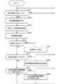
次に、上記システムの各装置の動作について説明する。図8は、実施の形態1に係る身体情報管理システムにおける管理サーバ2による身体情報送信要求の送信処理を説明するフローチャートである。図9は、実施の形態1に係る身体情報管理システムにおける管理サーバ2による身体情報の受信処理を説明するフローチャートである。図10は、実施の形態1に係る身体情報管理システムにおける無線通信装置1の動作を説明するフローチャートである。
【0074】
管理サーバ2は、ページャ管理テーブル51に登録されている無線通信装置1のいずれかを順番に選択していき(ステップS1)、その無線通信装置1から身体情報を取得するタイミングであるか否かを判断する(ステップS2)。そして、管理サーバ2は、身体情報を取得するタイミングである無線通信装置1へ身体情報の送信要求を送信する(ステップS3)。
【0075】
その際、管理サーバ2では、CPU41が、サーバプログラムに従って、各無線通信装置1から身体情報を取得するタイミングであるか否かを判断し、そのタイミングである無線通信装置1のページャ受信部22のページャ番号を特定し、公衆網インタフェース44を制御して、そのページャ番号へ発呼させ、その無線通信装置1のページャ受信部22へ向けて身体情報の送信要求を送信させる。
【0076】
その呼は、ページャシステム6に到達し、ページャシステム6は、その身体情報の送信要求を受け取ると、基地局7からそのページャ番号を有するページャ受信部22へ向けて電波としてその身体情報の送信要求を送信させる。
【0077】
一方、無線通信装置1では、ページャ受信部22の電源は待機中でもオン状態とされており、ページャ受信部22は、自己のページャ番号宛ての身体情報の送信要求を受信するまで待機している(ステップS21)。そして、自己のページャ番号宛ての身体情報の送信要求を受信すると、その身体情報の送信要求がページャ受信部22から電源制御部29に供給される。電源制御部29は、その送信要求を受け取ると、まず、バッテリ28による電源電力を制御部24(および必要に応じてセンサ部23)へ供給して(ステップS22)、身体情報を取得させる(ステップS23)。その次に、電源制御部29は、バッテリ28による電源電力を無線部21へ供給する(ステップS24)。ここでは、制御部24(および必要に応じてセンサ部23)、無線部21の順番に電源をオンしているが、両者の電源を同時にオンするようにしてもよい。
【0078】
無線部21に電源電力が供給されると、無線部21は、制御部24による制御に応じて、管理サーバ2への接続を試みる(ステップS25)。そして、制御部24は、管理サーバ2への接続が成功したか否かを監視し(ステップS26)、管理サーバ2への接続が成功した場合には、取得した身体情報を管理サーバ2へ送信させる(ステップS27)。そして、送信が完了した後に、電源制御部29は、無線部21、並びに制御部24(および必要に応じてセンサ部23)の電源をオフする(ステップS28)。これにより、無線通信装置1は、待機状態に戻る(ステップS21)。なお、身体情報を管理サーバ2へ送信する場合、無線通信装置1は、自己に固有の識別情報を身体情報に付加して送信する。この識別情報としては、例えば、ページャ受信部22のページャ番号、加入者IDなどを使用することができる。また、無線部21に割り当てられている電話番号を使用するようにしてもよい。
【0079】
なお、管理サーバ2への接続に失敗した場合には、電源制御部29が、無線部21、並びに制御部24(および必要に応じてセンサ部23)の電源をオフし(ステップS28)、無線通信装置1は待機状態に戻る(ステップS21)。
【0080】
また、管理サーバ2は、身体情報の受信を監視しており(ステップS11)、身体情報を受信すると、付加されている識別情報から無線通信装置1を特定し(ステップS12)、その無線通信装置1に関連付けてその身体情報を記録する(ステップS13)。その際、管理サーバ2では、CPU41が、サーバプログラムに従って、公衆網インタフェース44による身体情報の受信を監視し、身体情報を受信すると、その無線通信装置1の加入者IDに関連付けてその身体情報を身体情報テーブル52に記録する。
【0081】
そして、管理サーバ2は、今回受信した身体情報、あるいは今回および過去の身体情報を含めた身体情報の履歴を解析し(ステップS14)、その解析結果に基づいて、管理対象101の健康状態に異常があるか否かを判定する(ステップS15)。管理サーバ2は、異常がないと判定した場合には、そのまま待機状態(ステップS11)に戻る。
【0082】
一方、管理サーバ2は、異常があると判定した場合には、登録されている通知先にその旨を通知し(ステップS16)、その後、待機状態(ステップS11)に戻る。その際、管理サーバ2では、CPU41が、サーバプログラムに従って、ページャ管理テーブル51から通知先情報として電話番号や電子メールアドレスを読み出し、公衆網インタフェース44を制御してその電話番号へ電話によりその旨を通知したり、図示せぬコンピュータネットワークに接続し、電子メールアドレスへ電子メールによりその旨を通知したりする。
【0083】
以上のように、上記実施の形態1によれば、管理対象101に装着される無線通信装置1では、センサ部23および制御部24が、管理対象101の身体情報を取得し、受信専用のページャ受信部22が、身体情報の送信要求を受信し、電源制御部29が、ページャ受信部22により身体情報の送信要求が受信されると無線部21の電源をオンし身体情報を送信させ、送信後に無線部21の電源をオフする。一方、管理サーバ2は、公衆網インタフェース44により、無線通信装置1へ身体情報の送信要求を送信し、無線通信装置1から身体情報を受信する。
【0084】
これにより、無線通信装置1で消費される電力を低減し、バッテリ28などの電源を充電、交換などせずに使用できる期間を長くすることができる。ひいては、バッテリ28などの電源を充電、交換する頻度が減り、管理対象101の身体情報をより定常的に取得することができる。
【0085】
また、上記実施の形態1によれば、無線通信装置1の電源制御部29が、ページャ受信部22により身体情報の送信要求が受信されると制御部24(および必要に応じてセンサ部23)の電源をオンし、制御部24およびセンサ部23に身体情報を取得させ、取得後に制御部24(および必要に応じてセンサ部23)の電源をオフする。
【0086】
これにより、無線通信装置1で消費される電力をより低減し、バッテリ28などの電源を充電、交換などせずに使用できる期間をより長くすることができる。
【0087】
さらに、上記実施の形態1によれば、無線通信装置1の無線送信手段としてPHSを使用する無線部21を使用するので、無線通信装置1による身体情報の送信時の消費電力をより低減することができる。また、身体情報の送信時の電磁波による管理対象への影響を少なくすることができる。
【0088】
さらに、上記実施の形態1によれば、無線通信装置1の無線受信手段として、ページャシステムを使用するページャ受信部22を使用するので、管理サーバ2からの要求を受信するために待機している際の無線通信装置1の消費電力を低減することができる。
【0089】
さらに、上記実施の形態1によれば、無線通信装置1のセンサ部23および制御部24が、管理対象101の身体情報として、脈拍、血圧、体温、並びにペースメーカの制御情報および/または設定情報のうちの少なくとも1つを取得する。これにより、管理対象101の状況を正確に把握することができる。
【0090】
実施の形態2.
本発明の実施の形態2に係る身体情報管理システムは、さらに、身体情報の値に応じて、管理サーバ2が身体情報を取得する時間間隔を変更するようにしたものである。
【0091】
なお、本発明の実施の形態2に係る身体情報管理システムにおける無線通信装置1は、実施の形態1の場合と同様のものである。
【0092】
一方、本発明の実施の形態2に係る身体情報管理システムにおける管理サーバ2は、実施の形態1の場合の管理サーバ2に、身体情報の値に応じて、身体情報を取得する時間間隔を変更する機能を追加したものである。すなわち、管理サーバ2のCPU41がサーバプログラムを実行することで、身体情報に基づいて、身体情報の送信要求を送信する時間間隔を制御するサーバ側制御手段が実現される。
【0093】
実施の形態2に係る身体情報管理システムにおける管理サーバ2が記憶するページャ管理テーブル51には、身体情報の送信要求を送信する時間間隔として、身体情報取得時間間隔が、無線通信装置1ごとに設定されている。
【0094】
図11は、実施の形態2におけるページャ管理テーブル51の一例を示す図である。図11に示すように、この実施の形態2におけるページャ管理テーブル51には、各無線通信装置1に対応する各加入者IDに関連付けて身体情報取得時間間隔が設定されている。
【0095】
そして、実施の形態2に係る身体情報管理システムにおける管理サーバ2は、その身体情報取得時間間隔および身体情報テーブル52の最も新しい受信日時から各無線通信装置1への身体情報の送信要求の送信タイミングを特定する機能、および受信した身体情報の値に基づいてこの身体情報取得時間間隔を変更する機能を有する。このような機能は、実施の形態1の場合の管理サーバ2用のサーバプログラムを変更することで実現可能である。
【0096】
なお、実施の形態2に係る身体情報管理システムにおけるその他の構成要素については実施の形態1の場合と同様であるので、その説明を省略する。
【0097】
次に、上記システムにおける管理サーバ2の動作について説明する。図12は、実施の形態2に係る身体情報管理システムにおける管理サーバ2による身体情報の受信処理を説明するフローチャートである。なお、身体情報の送信要求を送信する際の管理サーバ2の動作は実施の形態1の場合と同様であるので、その説明を省略する。また、上記システムにおける無線通信装置1の動作は実施の形態1の場合と同様であるので、その説明を省略する。
【0098】
管理サーバ2は、身体情報の受信を監視しており(ステップS41)、身体情報を受信すると、実施の形態1と同様にして、付加されている識別情報から無線通信装置1を特定し(ステップS42)、その無線通信装置1に関連付けてその身体情報を記録する(ステップS43)。
【0099】
そして、管理サーバ2は、今回受信した身体情報、または今回および過去の身体情報を含めた身体情報の履歴を解析し(ステップS44)、その解析結果に基づいて、まず、管理対象101の健康状態に異常があるか否かを判定する(ステップS45)。管理サーバ2は、異常があると判定した場合には、登録されている通知先にその旨を通知し(ステップS46)、その後、待機状態(ステップS41)に戻る。なお、通知先への通知の方法は、実施の形態1の場合と同様である。
【0100】
一方、管理サーバ2は、異常がないと判定した場合には、次に、解析結果に基づいて、健康状態が要注意状態であるか否かを判定する(ステップS47)。すなわち、管理サーバ2は、身体情報の値が平常値の範囲と異常値の範囲との中間の要注意の範囲内にあるか否かや身体情報の変動量などを考慮して、管理対象101の健康状態が要注意状態であるか否かを判定する。その際、管理サーバ2では、CPU41が、サーバプログラムに従って、そのような判定を行う。
【0101】
そして、管理対象101の健康状態が要注意状態であると判定した場合には、管理サーバ2は、身体情報取得時間間隔を短くするように変更し(ステップS48)、その後、待機状態(ステップS41)に戻る。これにより、次回の身体情報の送信要求の送信タイミングが早まることになる。その際、管理サーバ2では、CPU41が、サーバプログラムに従って、記憶部45に記憶されたページャ管理テーブル51におけるその管理対象101の無線通信装置1に対応する身体情報取得時間間隔の値を変更する。
【0102】
一方、管理対象101の健康状態が要注意状態ではないと判定した場合には、管理対象101の健康状態が平常状態であるので、管理サーバ2は、ページャ管理テーブル51に現在設定されている身体情報取得時間間隔が所定の平常値であるか否かを判断し(ステップS49)、その身体情報取得時間間隔が所定の平常値ではない場合には、その身体情報取得時間間隔を所定の平常値に変更する(ステップS50)。ここでは、図11に示すように、身体情報取得時間間隔の平常値は、60分に設定されている。ただし、身体情報取得時間間隔の平常値は、60分以外としてもよい。また、身体情報取得時間間隔の平常値は、管理対象101の種別に応じて設定されるようにしてもよい。なお、その身体情報取得時間間隔が所定の平常値である場合には、管理サーバ2は、そのまま待機状態(ステップS41)に戻る。
【0103】
つまり、管理対象101の異常状態が検知された場合には、その旨の通知がなされ、要注意状態が検知された場合には、身体情報の取得時間間隔が狭められ、平常状態に復帰した場合には、身体情報の取得時間間隔が平常値に戻される。
【0104】
以上のように、上記実施の形態2によれば、管理サーバ2のCPU41は、サーバプログラムに従って、身体情報に基づいて、身体情報の送信要求を送信する時間間隔を制御する。これにより、管理対象101の状況に応じた頻度で身体情報を取得しつつ、無線通信装置1の消費電力を適切に低減することができる。
【0105】
また、上記実施の形態2によれば、管理サーバ2のCPU41が、サーバプログラムに従って、身体情報が所定の条件を満足すると、身体情報の送信要求の送信時間間隔を短くする。これにより、無線通信装置1の消費電力を低減しつつ、状況に応じて自動的に管理対象101の健康状態をより細かく監視することができる。
【0106】
実施の形態3.
本発明の実施の形態3に係る身体情報管理システムは、実施の形態1に係る身体情報管理システムにおいて、無線通信装置1が自律的に所定の時間間隔で身体情報を管理サーバ2に送信し、管理サーバ2が身体情報の解析結果に応じて身体情報の送信時間間隔を変更、設定する要求を無線通信装置1に送信するようにしたものである。
【0107】
なお、実施の形態3における管理サーバ2の基本的な構成は、実施の形態1の場合と同様であるので、その説明を省略する。ただし、実施の形態3における管理サーバ2は、身体情報の送信要求を送信しない。その代わりに、実施の形態3における管理サーバ2は、身体情報の解析結果に基づいて、必要に応じて、身体情報の送信時間間隔を変更させる要求を無線通信装置1のページャ受信部22へ送信する。実施の形態1における管理サーバ2のサーバプログラムを変更することで、この実施の形態3における管理サーバ2を実現することができる。すなわち、CPU41がサーバプログラムを実行することで、身体情報に基づいて、身体情報の送信時間間隔を決定する時間間隔決定手段が実現される。
【0108】
図13は、本発明の実施の形態3に係る身体情報管理システムにおける無線通信装置1の構成を示すブロック図である。図13において、電源制御部29Aは、この無線通信装置1内の各電子回路に対して電源電力を供給するか否かを制御する回路である。この実施の形態3においては、電源制御部29Aは、所定の時間間隔で無線部21の電源をオンし身体情報を送信させ、送信後に無線部21の電源をオフし、また身体情報を送信する時間間隔を、ページャ受信部22により受信された送信時間間隔に変更する電源制御手段として機能する。
【0109】
また、タイマ31は、メモリ32に記憶された時間間隔を計時し、時間間隔ごとに所定の信号を電力制御部29Aに出力するタイマ回路であり、メモリ32は、身体情報の送信時間間隔を記憶するメモリである。なお、タイマ31およびメモリ32には、待機中も電源電力が供給されている。
【0110】
なお、図13におけるその他の構成要素については実施の形態1の場合と同様であるので、その説明を省略する。
【0111】
また、実施の形態3に係る身体情報管理システムのその他の構成要素については実施の形態1の場合と同様であるので、その説明を省略する。
【0112】
次に、上記装置の動作について説明する。図14は、実施の形態3に係る身体情報管理システムにおける無線通信装置1の動作を説明するフローチャートである。図15は、実施の形態3に係る身体情報管理システムにおける管理サーバ2の動作を説明するフローチャートである。
【0113】
無線通信装置1は、内蔵のタイマ31により身体情報を送信する時間間隔を計時しており、身体情報の送信タイミングになるか、その時間間隔の変更要求をページャ受信部22により受信するまで待機する(ステップS61,S71)。その際、無線通信装置1では、電源制御部29Aが、タイマ31からの送信タイミングを示す信号を受け取るか、ページャ受信部22により送信時間間隔の変更要求が受信されるまで、無線部21、制御部24(およびセンサ部23)などに電源電力を供給せずに待機している。
【0114】
そして、身体情報の送信タイミングになると、無線通信装置1は、実施の形態1の場合(ステップS22〜S28)と同様にして、身体情報の取得および送信の処理を行う(ステップS62〜S68)。
【0115】
また、この無線通信装置1のページャ番号宛ての身体情報の送信時間間隔の変更要求がページャ受信部22により受信されると、その身体情報の送信時間間隔の変更要求がページャ受信部22から電源制御部29Aに供給される。
【0116】
電源制御部29Aは、その身体情報の送信時間間隔の変更要求を受け取ると、その身体情報の送信時間間隔で、メモリ32に記憶されている身体情報の送信時間間隔の値を更新する(ステップS72)。これにより、タイマ31により計時される時間間隔が変更され、身体情報の取得および送信の時間間隔が変更される。
【0117】
一方、管理サーバ2は、実施の形態1の場合(ステップS11〜S14)と同様に、身体情報を受信すると、その身体情報の送信元の無線通信装置1を特定し、その身体情報を記録するとともに、その身体情報を解析する(ステップS81〜S84)。
【0118】
そして、管理サーバ2は、その解析結果に基づいて、まず、管理対象101の健康状態に異常があるか否かを判定する(ステップS85)。管理サーバ2は、異常があると判定した場合には、登録されている通知先にその旨を通知し(ステップS86)、その後、待機状態(ステップS81)に戻る。なお、通知先への通知の方法は、実施の形態1の場合と同様である。
【0119】
一方、管理サーバ2は、異常がないと判定した場合には、次に、解析結果に基づいて、健康状態が変化したか否かを判定する(ステップS87)。その際、例えば、管理サーバ2は、身体情報の値が平常値の範囲および要注意の範囲のいずれかに入るかを判断し、前回の判断結果と比較して、身体情報の値が入る範囲に変化があったかなどを考慮して、管理対象101の健康状態が変化したか否かを判定する。その際、管理サーバ2では、CPU41が、サーバプログラムに従って、そのような判定を行う。
【0120】
そして、管理対象101の健康状態が変化したと判定した場合には、管理サーバ2は、その変化に応じた身体情報の送信時間間隔を決定し、その時間間隔へ送信時間間隔を変更させる要求を送信し(ステップS88)、その後、待機状態(ステップS81)に戻る。身体情報が平常の範囲から要注意の範囲へ変化した場合には、身体情報の送信時間間隔は短くされ、身体情報が要注意の範囲から平常の範囲へ変化した場合には、身体情報の送信時間間隔は長くされる。これにより、次回の身体情報の取得および送信のタイミングが、管理対象101の健康状態に応じて早くなったり遅くなったりする。
【0121】
以上のように、上記実施の形態3によれば、管理対象101に装着される無線通信装置では、センサ部23および制御部24が、管理対象101の身体情報を取得し、無線部21が、センサ部23および制御部24により取得された身体情報を送信し、ページャ受信部22が、身体情報の送信時間間隔を受信し、電源制御部29Aが、所定の時間間隔で無線部21の電源をオンし身体情報を送信させ、送信後に無線部21の電源をオフし、身体情報を送信する時間間隔を、ページャ受信部22により受信された送信時間間隔に変更する。一方、管理サーバ2は、公衆網インタフェース44により、身体情報を受信し、身体情報の送信時間間隔の設定情報を送信し、サーバプログラムを実行するCPU41により、身体情報に基づいて、身体情報の送信時間間隔を決定する。
【0122】
これにより、無線通信装置1で消費される電力を低減し、バッテリ28などの電源を充電、交換などせずに使用できる期間を長くすることができる。ひいては、バッテリ28などの電源を充電、交換する頻度が減り、管理対象101の身体情報をより定常的に取得することができる。また、管理対象101の状況に応じた頻度で身体情報を取得しつつ、無線通信装置1の消費電力を適切に低減することができる。
【0123】
また、上記実施の形態3によれば、無線通信装置1の電源制御部29Aが、同様の時間間隔で制御部24(および必要に応じてセンサ部23)の電源をオンし身体情報を取得させ、取得後に制御部24(および必要に応じてセンサ部23)の電源をオフする。これにより、無線通信装置1で消費される電力をより低減し、バッテリ28などの電源を充電、交換などせずに使用できる期間をより長くすることができる。
【0124】
さらに、上記実施の形態3によれば、無線通信装置1の無線送信手段として、PHSを使用する無線部21を使用するので、無線通信装置1による身体情報の送信時の消費電力をより低減することができる。また、身体情報の送信時の電磁波による管理対象への影響を少なくすることができる。
【0125】
さらに、上記実施の形態3によれば、無線通信装置1の無線受信手段として、ページャシステムを使用するページャ受信部22を使用するので、管理サーバ2からの要求を受信するために待機している際の無線通信装置1の消費電力を低減することができる。
【0126】
さらに、上記実施の形態3によれば、無線通信装置1のセンサ部23および制御部24が、管理対象101の身体情報として、脈拍、血圧、体温、並びにペースメーカの制御情報および/または設定情報のうちの少なくとも1つを取得する。これにより、管理対象101の状況を正確に把握することができる。
【0127】
実施の形態4.
本発明の実施の形態4に係る身体情報管理システムは、実施の形態3に係る身体情報管理システムにおいて、無線通信装置1が身体情報を解析し、身体情報を管理サーバ2へ送信する必要があると判断した場合のみ送信するようにしたものである。その他の各装置の構成および動作については実施の形態3と同様であるので、その説明を省略する。
【0128】
以上のように、上記実施の形態4によれば、身体情報の送信頻度をより低くでき、無線通信装置1の消費電力をより低減することができる。
【0129】
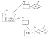
実施の形態5.
本発明の実施の形態5に係る身体情報管理システムは、ページャシステムのページャ制御サーバに管理サーバ2の機能を追加したものを管理サーバ2Aとしたものである。図16は、本発明の実施の形態5に係る身体情報管理システムの構成を示すブロック図である。図16において、管理サーバ2Aは、管理サーバ2と同様に機能するとともに、ページャ制御サーバを兼ねるサーバである。
【0130】
図17は、実施の形態5に係る身体管理システムにおける管理サーバ2Aの構成を示すブロック図である。図17において、ページャインタフェース81は、基地局7を介して特定のページャ受信部22へ各種情報を送信可能な送信手段としての送信回路である。なお、図17におけるその他の構成要素については実施の形態1の場合と同様であるので、その説明を省略する。
【0131】
なお、実施の形態5に係る身体情報管理システムにおけるその他の構成要素については、実施の形態1〜4のいずれかと同一とすればよく、その説明は省略する。
【0132】
以上のように、上記実施の形態5によれば、実施の形態1〜4のいずれかと同様の効果が得られる。
【0133】
なお、上述の各実施の形態は、本発明の好適な例であるが、本発明は、これらに限定されるものではなく、本発明の要旨を逸脱しない範囲において、種々の変形、変更が可能である。
【0134】
例えば、無線通信装置1に、管理対象101からのセンサ部23の離脱を感知する着脱センサを設け、離脱時に、無線通信装置1が身体情報の取得および/または送信を行わないようにしたり、離脱の通知を管理サーバ2へ送信するようにしてもよい。
【0135】
また、入浴時や運動時を通知するための操作部を入力装置26に設け、ユーザによりその操作部が操作された場合に、制御部24は、無線部21の電源をオンさせ、無線部21を制御して、その旨を管理サーバ2へ通知するようにしてもよい。
【0136】
さらに、上記各実施の形態では、1回の測定による身体情報に基づいて身体情報の取得および/または送信の時間間隔を変更するようにしてもよいし、身体情報が所定の条件を満足することが所定回数連続した場合に変更するようにしてもよい。
【0137】
さらに、上記各実施の形態において、管理対象101が要注意状態から平常状態へ復帰した後も、所定の期間については、身体情報の取得および/または送信の時間間隔を狭めたままにしておくようにしてもよい。
【0138】
さらに、上記各実施の形態において、無線通信装置1が、複数回の取得された身体情報をまとめて管理サーバ2へ送信するようにしてもよい。それにより、無線通信装置1による身体情報の送信頻度が減り、より消費電力を低減することができる。
【0139】
【発明の効果】
本発明によれば、身体情報を取得する無線通信装置で消費される電力を低減し、バッテリなどの電源を充電、交換などせずに使用できる期間を長くすることができる。
【図面の簡単な説明】
【図1】図1は、本発明の実施の形態1に係る身体情報管理システムの構成を示すブロック図である。
【図2】図2は、実施の形態1に係る身体管理システムにおける無線通信装置の構成を示すブロック図である。
【図3】図3は、実施の形態1に係る身体管理システムにおける管理サーバの構成を示すブロック図である。
【図4】図4は、実施の形態1におけるページャ管理テーブルの一例を示す図である。
【図5】図5は、実施の形態1における身体情報テーブルの一例を示す図である。
【図6】図6は、管理対象への無線通信装置の装着の一例を示す図である。
【図7】図7は、管理対象への無線通信装置の装着の他の例を示す図である。
【図8】図8は、実施の形態1に係る身体情報管理システムにおける管理サーバによる身体情報送信要求の送信処理を説明するフローチャートである。
【図9】図9は、実施の形態1に係る身体情報管理システムにおける管理サーバによる身体情報の受信処理を説明するフローチャートである。
【図10】図10は、実施の形態1に係る身体情報管理システムにおける無線通信装置の動作を説明するフローチャートである。
【図11】図11は、実施の形態2におけるページャ管理テーブルの一例を示す図である。
【図12】図12は、実施の形態2に係る身体情報管理システムにおける管理サーバによる身体情報の受信処理を説明するフローチャートである。
【図13】図13は、本発明の実施の形態3に係る身体情報管理システムにおける無線通信装置の構成を示すブロック図である。
【図14】図14は、実施の形態3に係る身体情報管理システムにおける無線通信装置の動作を説明するフローチャートである。
【図15】図15は、実施の形態3に係る身体情報管理システムにおける管理サーバの動作を説明するフローチャートである。
【図16】図16は、本発明の実施の形態5に係る身体情報管理システムの構成を示すブロック図である。
【図17】図17は、実施の形態5に係る身体管理システムにおける管理サーバの構成を示すブロック図である。
【符号の説明】
1 無線通信装置
2,2A 管理サーバ
23 センサ部(身体情報取得手段)
24 制御部(身体情報取得手段)
21 無線部(無線送信手段)
22 ページャ受信部(無線受信手段)
29,29A 電源制御部(電源制御手段)
41 CPU(サーバ側制御手段、時間間隔決定手段)
44 公衆網インタフェース(送信手段、受信手段)
81 ページャインタフェース(送信手段)
101 管理対象[0001]
TECHNICAL FIELD OF THE INVENTION
The present invention relates to a physical information management system and a physical information management method for acquiring and managing physical information to be managed, and a wireless communication device used in the physical information management system and the physical information management method.
[0002]
[Prior art]
As a conventional physical information management system, there is a system that transmits physical information (health data) measured by a measuring unit such as a urine analyzer or a sphygmomanometer to an external server such as a hospital to perform health management (for example, Patent Document 1).
[0003]
There are also electronic thermometers that measure a user's body temperature and display measurement data, and electronic sphygmomanometers that measure a user's blood pressure and pulse and display measurement data.
[0004]
[Patent Document 1]
JP 2000-83908 A (paragraphs 0020 to 0029)
[0005]
[Problems to be solved by the invention]
However, when a wireless communication device having a measurement unit for measuring physical information is attached to a body to be managed such as a user and the physical information is transmitted to an external server using wireless communication, the transmission circuit of the wireless communication device is used. There is a problem that the power of the battery of the wireless communication device runs out in a short time due to power consumption.
[0006]
The present invention has been made in view of the above problems, and reduces power consumed by a wireless communication device that acquires physical information to be managed, and can be used without charging or replacing a power source such as a battery. It is an object of the present invention to obtain a physical information management system and a physical information management method capable of extending a period, and a wireless communication device used in the physical information management system and the physical information management method.
[0007]
[Means for Solving the Problems]
In order to solve the above problem, a physical information management system of the present invention includes a wireless communication device mounted on a management target and a management server. The wireless communication device includes a physical information acquisition unit that acquires physical information to be managed, a wireless transmission unit that transmits the physical information acquired by the physical information acquisition unit, and a reception-only wireless device that receives a transmission request for the physical information. A receiving unit, and a power control unit for turning on the power of the wireless transmitting unit to transmit the physical information when the transmission request for the physical information is received by the wireless receiving unit, and for turning off the power of the wireless transmitting unit after the transmission. The management server includes a management server having a transmitting unit that transmits a request for transmitting physical information to the wireless communication device, and a receiving unit that receives physical information from the wireless communication device.
[0008]
When this physical information management system is used, the power consumed by the wireless communication device can be reduced, and the period during which a power supply such as a battery can be used without being charged or replaced can be extended. As a result, the frequency of charging and exchanging a power source such as a battery is reduced, and the physical information to be managed can be obtained more constantly.
[0009]
Further, the physical information management system according to the present invention includes, in addition to the physical information management system according to the above invention, a server-side control unit that controls a time interval at which a transmission request for the physical information is transmitted to the management server based on the physical information. Things.
[0010]
By using this physical information management system, it is possible to appropriately reduce the power consumption of the wireless communication device while acquiring physical information at a frequency according to the management target situation.
[0011]
Further, in the physical information management system according to the present invention, in addition to the physical information management system according to any of the above inventions, when the physical information satisfies a predetermined condition, the server-side control means sets the transmission time interval of the physical information transmission request. It is intended to be shorter.
[0012]
By using this physical information management system, it is possible to automatically and more closely monitor the health condition of the management target according to the situation while reducing the power consumption of the wireless communication device.
[0013]
Further, the physical information management system of the present invention, in addition to the physical information management system of any of the above inventions, further comprises: The power of the means is turned on, the physical information acquiring means acquires the physical information, and the power of the physical information acquiring means is turned off after the acquisition.
[0014]
When this physical information management system is used, the power consumed by the wireless communication device can be further reduced, and the period during which a power supply such as a battery can be used without being charged or replaced can be extended.
[0015]
Further, in the physical information management system of the present invention, in addition to the physical information management system of the above invention, the wireless transmission unit of the wireless communication device collectively transmits the physical information acquired a plurality of times by the physical information acquisition unit. It is intended to be.
[0016]
When this physical information management system is used, the frequency of transmitting physical information by the wireless communication device is reduced, and power consumption can be further reduced.
[0017]
Further, the physical information management system of the present invention includes a wireless device using a PHS as a wireless transmission unit of the wireless communication device in addition to any of the physical information management systems of the above invention.
[0018]
By using this physical information management system, it is possible to further reduce the power consumption when transmitting the physical information by the wireless communication device. In addition, it is possible to reduce the influence of the electromagnetic wave on the management target when transmitting the physical information.
[0019]
Further, a physical information management system according to the present invention includes a wireless device using a pager system as a wireless receiving unit of the wireless communication device, in addition to any of the physical information management systems according to the present invention.
[0020]
By using this physical information management system, it is possible to reduce the power consumption of the wireless communication device when waiting to receive a request from the management server.
[0021]
Further, in the physical information management system of the present invention, in addition to any one of the physical information management systems of the above invention, the physical information acquisition means of the wireless communication device includes a pulse, a blood pressure, a body temperature, and a pacemaker as physical information to be managed. At least one of the control information and / or the setting information is obtained.
[0022]
By using this physical information management system, the situation of the management target can be accurately grasped.
[0023]
A wireless communication device according to the present invention is a wireless communication device mounted on a management target, wherein a physical information acquisition unit that acquires physical information of the management target, and a wireless transmission that transmits the physical information acquired by the physical information acquisition unit. Means, a receiving-only wireless receiving means for receiving a request for transmitting physical information, and, when a request for transmitting physical information is received by the wireless receiving means, turning on the power of the wireless transmitting means and transmitting the physical information, Power supply control means for turning off the power of the transmission means.
[0024]
When this wireless communication device is used, power consumption in the wireless communication device is reduced, and a period during which a power supply such as a battery can be used without being charged or replaced can be extended. As a result, the frequency of charging and exchanging a power source such as a battery is reduced, and the physical information to be managed can be obtained more constantly.
[0025]
The physical information management system of the present invention includes a wireless communication device mounted on a management target and a management server. The wireless communication device includes: a physical information acquiring unit that acquires physical information to be managed; a wireless transmitting unit that transmits the physical information acquired by the physical information acquiring unit; and a receiving unit that receives information of a transmission time interval of the physical information. The dedicated wireless receiving means and the power source of the wireless transmitting means are turned on at predetermined time intervals to transmit the physical information, the power source of the wireless transmitting means is turned off after the transmission, and the time interval for transmitting the physical information is received. Power supply control means for changing the transmission time interval. The management server includes: a receiving unit that receives the physical information; a time interval determining unit that determines a transmission time interval of the physical information based on the physical information; and a transmitting unit that transmits information of the transmission time interval of the physical information. Have.
[0026]
When this physical information management system is used, the power consumed by the wireless communication device can be reduced, and the period during which a power supply such as a battery can be used without being charged or replaced can be extended. As a result, the frequency of charging and exchanging a power source such as a battery is reduced, and the physical information to be managed can be obtained more constantly. Further, by using this physical information management system, it is possible to appropriately reduce the power consumption of the wireless communication device while acquiring physical information at a frequency according to the situation of the management target.
[0027]
Further, in the physical information management system of the present invention, in addition to the physical information management system of the above invention, the power supply control means of the wireless communication device, together with the wireless transmission means, turns on the power of the physical information acquisition means at the time interval and outputs the physical information. And turning off the power of the physical information acquisition means after the acquisition.
[0028]
When this physical information management system is used, the power consumed by the wireless communication device can be further reduced, and the period during which a power supply such as a battery can be used without being charged or replaced can be extended.
[0029]
Further, in the physical information management system of the present invention, in addition to the physical information management system of the above invention, the wireless transmission unit of the wireless communication device collectively transmits the physical information acquired a plurality of times by the physical information acquisition unit. It is intended to be.
[0030]
When this physical information management system is used, the frequency of transmitting physical information by the wireless communication device is reduced, and power consumption can be further reduced.
[0031]
Further, the physical information management system of the present invention has a wireless device using a PHS as a wireless transmission unit of the wireless communication device, in addition to any of the physical information management systems of the above invention.
[0032]
By using this physical information management system, it is possible to further reduce the power consumption when transmitting the physical information by the wireless communication device. In addition, it is possible to reduce the influence of the electromagnetic wave on the management target when transmitting the physical information.
[0033]
Further, a physical information management system according to the present invention includes a wireless device using a pager system as a wireless receiving unit of the wireless communication device, in addition to any of the physical information management systems according to the present invention.
[0034]
By using this physical information management system, it is possible to reduce the power consumption of the wireless communication device when waiting to receive a request from the management server.
[0035]
Further, in the physical information management system of the present invention, in addition to any one of the physical information management systems of the above invention, the physical information acquisition means of the wireless communication device includes a pulse, a blood pressure, a body temperature, and a pacemaker as physical information to be managed. At least one of the control information and / or the setting information is obtained.
[0036]
By using this physical information management system, the situation of the management target can be accurately grasped.
[0037]
A wireless communication device according to the present invention is a wireless communication device mounted on a management target, wherein a physical information acquisition unit that acquires physical information of the management target, and a wireless transmission that transmits the physical information acquired by the physical information acquisition unit. Means, receiving-only wireless receiving means for receiving information on the transmission time interval of the physical information, and powering on the wireless transmitting means at predetermined time intervals to transmit the physical information, and turning off the wireless transmitting means after transmission Power supply control means for changing the time interval for transmitting the physical information to the received transmission time interval.
[0038]
When this wireless communication device is used, power consumption in the wireless communication device is reduced, and a period during which a power supply such as a battery can be used without being charged or replaced can be extended. As a result, the frequency of charging and exchanging a power source such as a battery is reduced, and the physical information to be managed can be obtained more constantly.
[0039]
The physical information management method according to the present invention includes a step of acquiring physical information to be managed by a wireless communication device attached to the management target, and a request to transmit the physical information to the wireless communication device by a management server that manages the physical information. Transmitting, a step of receiving a request for transmission of body information by a reception-only wireless reception unit of the wireless communication device, and turning on a power of the wireless transmission unit of the wireless communication device in response to the reception of the request for transmission of body information. Transmitting the physical information to the management server by the wireless transmission means, and receiving the physical information by the management server.
[0040]
By using this physical information management method, the power consumed by the wireless communication device that acquires physical information can be reduced, and the period during which a power supply such as a battery can be used without being charged or replaced can be extended. As a result, the frequency of charging and exchanging a power source such as a battery is reduced, and the physical information to be managed can be obtained more constantly.
[0041]
A physical information management method according to the present invention includes, in addition to the physical information management method according to the present invention, a step of controlling a time interval at which the wireless communication device transmits a transmission request for physical information from the management server based on the physical information.
[0042]
By using this physical information management method, it is possible to appropriately reduce the power consumption of the wireless communication device while acquiring physical information at a frequency according to the management target situation.
[0043]
The physical information management method of the present invention includes a step of acquiring physical information of a management target by a wireless communication device attached to the management target, and turning on a power of a wireless transmission unit of the wireless communication device at a predetermined time interval. Transmitting the physical information to the management server that manages the physical information by the transmitting unit; receiving the physical information by the management server; and transmitting the physical information from the wireless communication device based on the physical information by the management server. Determining a time interval, transmitting the determined transmission time interval to the wireless communication device by the management server, receiving the transmission time interval by a receiving-only wireless receiving unit of the wireless communication device, And changing the time interval for transmitting the physical information to the received transmission time interval.
[0044]
By using this physical information management method, the power consumed by the wireless communication device that acquires physical information can be reduced, and the period during which a power supply such as a battery can be used without being charged or replaced can be extended. As a result, the frequency of charging and exchanging a power source such as a battery is reduced, and the physical information to be managed can be obtained more constantly.
[0045]
BEST MODE FOR CARRYING OUT THE INVENTION
Hereinafter, an embodiment of the present invention will be described with reference to the drawings.
[0046]
FIG. 1 is a block diagram showing a configuration of a physical information management system according to
[0047]
In the first embodiment, when a transmission request for physical information is received by the
[0048]
Note that the
[0049]
Further, the
[0050]
The
[0051]
The
[0052]
In addition, the pager system 6 includes a pager control server (not shown) and the like, and when receiving information addressed to the pager together with a call addressed to the pager, transmits the information to the pager via the base station 7. In the first embodiment, the
[0053]
FIG. 2 is a block diagram showing a configuration of the
[0054]
The
[0055]
In addition, the
[0056]
The
[0057]
The
[0058]
The
[0059]
The
[0060]
The
[0061]
FIG. 3 is a block diagram showing a configuration of the
[0062]
The
[0063]
The
[0064]
The
[0065]
The
[0066]
FIG. 4 is a diagram illustrating an example of the pager management table 51 according to the first embodiment. As shown in FIG. 4, the pager management table 51 includes, for each
[0067]
For example, in the pager management table 51 shown in FIG. 4, for a certain
[0068]
FIG. 5 is a diagram illustrating an example of the physical information table 52 according to the first embodiment. In the physical information table 52, as shown in FIG. 5, each physical information received from the plurality of
[0069]
For example, in the physical information table 52 illustrated in FIG. 5, a series of physical information transmitted from the
[0070]
Next, mounting of the
[0071]
FIG. 6 is a diagram illustrating an example of mounting the
[0072]
FIG. 7 is a diagram illustrating another example of mounting the
[0073]
Next, the operation of each device of the above system will be described. FIG. 8 is a flowchart illustrating a process of transmitting a physical information transmission request by
[0074]
The
[0075]
At that time, in the
[0076]
The call reaches the pager system 6. When the pager system 6 receives the request for transmitting the physical information, the pager system 6 transmits the request for transmitting the physical information as radio waves from the base station 7 to the
[0077]
On the other hand, in the
[0078]
When the power is supplied to the
[0079]
If the connection to the
[0080]
Further, the
[0081]
Then, the
[0082]
On the other hand, when it is determined that there is an abnormality, the
[0083]
As described above, according to the first embodiment, in the
[0084]
Thus, the power consumed by the
[0085]
Further, according to the first embodiment, when the
[0086]
As a result, the power consumed by the
[0087]
Furthermore, according to the first embodiment, since the
[0088]
Furthermore, according to the first embodiment, since the
[0089]
Furthermore, according to the first embodiment, the
[0090]
The physical information management system according to the second embodiment of the present invention further changes the time interval at which the
[0091]
The
[0092]
On the other hand, the
[0093]
In the pager management table 51 stored in the
[0094]
FIG. 11 is a diagram illustrating an example of the pager management table 51 according to the second embodiment. As shown in FIG. 11, in the pager management table 51 according to the second embodiment, physical information acquisition time intervals are set in association with each subscriber ID corresponding to each
[0095]
Then, the
[0096]
The other components in the physical information management system according to the second embodiment are the same as those in the first embodiment, and a description thereof will not be repeated.
[0097]
Next, the operation of the
[0098]
The
[0099]
Then, the
[0100]
On the other hand, when it is determined that there is no abnormality, the
[0101]
Then, when it is determined that the health state of the
[0102]
On the other hand, when it is determined that the health state of the
[0103]
In other words, when an abnormal state of the
[0104]
As described above, according to the second embodiment, the
[0105]
According to the second embodiment, when the physical information satisfies the predetermined condition according to the server program, the
[0106]
In the physical information management system according to
[0107]
Note that the basic configuration of the
[0108]
FIG. 13 is a block diagram showing a configuration of the
[0109]
The
[0110]
The other components in FIG. 13 are the same as those in the first embodiment, and a description thereof will not be repeated.
[0111]
Other components of the physical information management system according to the third embodiment are the same as those in the first embodiment, and a description thereof will be omitted.
[0112]
Next, the operation of the above device will be described. FIG. 14 is a flowchart illustrating an operation of
[0113]
The
[0114]
Then, when the transmission timing of the physical information comes, the
[0115]
When the request for changing the transmission time interval of the physical information addressed to the pager number of the
[0116]
When receiving the request for changing the transmission time interval of the physical information, the
[0117]
On the other hand, similarly to the case of the first embodiment (steps S11 to S14), when receiving the physical information, the
[0118]
Then, the
[0119]
On the other hand, when determining that there is no abnormality, the
[0120]
If it is determined that the health status of the
[0121]
As described above, according to the third embodiment, in the wireless communication device attached to the
[0122]
Thus, the power consumed by the
[0123]
Further, according to the third embodiment, the power
[0124]
Furthermore, according to the third embodiment, since the
[0125]
Further, according to the third embodiment, since the
[0126]
Furthermore, according to the third embodiment, the
[0127]
In the physical information management system according to the fourth embodiment of the present invention, in the physical information management system according to the third embodiment, the
[0128]
As described above, according to the fourth embodiment, the transmission frequency of the physical information can be reduced, and the power consumption of the
[0129]
The physical information management system according to
[0130]
FIG. 17 is a block diagram showing a configuration of the
[0131]
The other components in the physical information management system according to the fifth embodiment may be the same as those in any of the first to fourth embodiments, and a description thereof will be omitted.
[0132]
As described above, according to the fifth embodiment, the same effect as any of the first to fourth embodiments can be obtained.
[0133]
The embodiments described above are preferred examples of the present invention, but the present invention is not limited to these, and various modifications and changes can be made without departing from the spirit of the present invention. It is.
[0134]
For example, the
[0135]
Further, an operation unit for notifying when bathing or exercising is provided on the
[0136]
Further, in each of the above-described embodiments, the time interval of acquiring and / or transmitting the physical information may be changed based on the physical information obtained by one measurement, or the physical information may satisfy a predetermined condition. May be changed when is repeated a predetermined number of times.
[0137]
Further, in each of the above embodiments, the time interval between acquisition and / or transmission of physical information is kept narrow for a predetermined period even after the managed
[0138]
Furthermore, in each of the above embodiments, the
[0139]
【The invention's effect】
ADVANTAGE OF THE INVENTION According to this invention, the electric power consumed by the radio | wireless communication apparatus which acquires physical information can be reduced, and the period which can be used without charging and replacing a power supply, such as a battery, can be extended.
[Brief description of the drawings]
FIG. 1 is a block diagram showing a configuration of a physical information management system according to
FIG. 2 is a block diagram illustrating a configuration of a wireless communication device in the body management system according to the first embodiment;
FIG. 3 is a block diagram illustrating a configuration of a management server in the body management system according to the first embodiment;
FIG. 4 is a diagram illustrating an example of a pager management table according to the first embodiment;
FIG. 5 is a diagram showing an example of a physical information table according to the first embodiment.
FIG. 6 is a diagram illustrating an example of mounting a wireless communication device on a management target;
FIG. 7 is a diagram illustrating another example of mounting a wireless communication device on a management target;
FIG. 8 is a flowchart illustrating a transmission process of a physical information transmission request by the management server in the physical information management system according to the first embodiment.
FIG. 9 is a flowchart illustrating a process of receiving physical information by the management server in the physical information management system according to the first embodiment;
FIG. 10 is a flowchart illustrating an operation of the wireless communication device in the physical information management system according to the first embodiment.
FIG. 11 is a diagram illustrating an example of a pager management table according to the second embodiment;
FIG. 12 is a flowchart illustrating a process of receiving physical information by a management server in the physical information management system according to the second embodiment;
FIG. 13 is a block diagram showing a configuration of a wireless communication device in a physical information management system according to
FIG. 14 is a flowchart illustrating an operation of the wireless communication device in the physical information management system according to the third embodiment.
FIG. 15 is a flowchart illustrating an operation of the management server in the physical information management system according to the third embodiment.
FIG. 16 is a block diagram showing a configuration of a physical information management system according to
FIG. 17 is a block diagram showing a configuration of a management server in the physical management system according to the fifth embodiment.
[Explanation of symbols]
1 wireless communication device
2,2A management server
23 sensor unit (physical information acquisition means)
24 control unit (physical information acquisition means)
21 Radio section (wireless transmission means)
22 Pager receiver (wireless receiver)
29, 29A power control unit (power control means)
41 CPU (server-side control means, time interval determination means)
44 Public network interface (transmission means, reception means)
81 Pager interface (transmission means)
101 Management target
Claims (19)
上記無線通信装置へ上記身体情報の送信要求を送信する送信手段と、上記無線通信装置から上記身体情報を受信する受信手段とを有する管理サーバと、
を備えることを特徴とする身体情報管理システム。Physical information acquisition means for acquiring physical information to be managed, a wireless transmission means for transmitting the physical information acquired by the physical information acquisition means, a reception-only wireless reception means for receiving a transmission request for the physical information, Power supply control means for turning on the power of the wireless transmission means to transmit the physical information when the transmission request for the physical information is received by the wireless reception means, and for turning off the power of the wireless transmission means after transmission. A wireless communication device mounted on the management target,
A transmission unit that transmits the transmission request of the physical information to the wireless communication device, and a management server having a reception unit that receives the physical information from the wireless communication device,
A physical information management system comprising:
管理対象の身体情報を取得する身体情報取得手段と、
上記身体情報取得手段により取得された上記身体情報を送信する無線送信手段と、
上記身体情報の送信要求を受信する受信専用の無線受信手段と、
上記無線受信手段により上記身体情報の送信要求が受信されると上記無線送信手段の電源をオンし上記身体情報を送信させ、送信後に上記無線送信手段の電源をオフする電源制御手段と、
を備えることを特徴とする無線通信装置。In the wireless communication device attached to the management target,
Physical information acquisition means for acquiring physical information to be managed;
Wireless transmission means for transmitting the physical information acquired by the physical information acquisition means,
A receiving-only wireless receiving means for receiving the transmission request of the physical information,
Power control means for turning on the power of the wireless transmission means to transmit the physical information when the transmission request for the physical information is received by the wireless reception means, and for powering off the wireless transmission means after transmission;
A wireless communication device comprising:
上記身体情報を受信する受信手段と、上記身体情報に基づいて、上記身体情報の送信時間間隔を決定する時間間隔決定手段と、上記身体情報の送信時間間隔の情報を送信する送信手段とを有する管理サーバと、
を備えることを特徴とする身体情報管理システム。Physical information acquisition means for acquiring physical information to be managed, wireless transmission means for transmitting the physical information acquired by the physical information acquisition means, and reception-only radio for receiving information on the transmission time interval of the physical information Receiving means for turning on the power of the wireless transmitting means at predetermined time intervals to transmit the physical information, turning off the power of the wireless transmitting means after transmission, and receiving a time interval for transmitting the physical information, Power supply control means to change to the transmission time interval, the wireless communication device attached to the management target,
A receiving unit that receives the physical information; a time interval determining unit that determines a transmission time interval of the physical information based on the physical information; and a transmitting unit that transmits information of the transmission time interval of the physical information. An administration server,
A physical information management system comprising:
上記管理対象の身体情報を取得する身体情報取得手段と、
上記身体情報取得手段により取得された上記身体情報を送信する無線送信手段と、
上記身体情報の送信時間間隔の情報を受信する受信専用の無線受信手段と、
所定の時間間隔で上記無線送信手段の電源をオンし上記身体情報を送信させ、送信後に上記無線送信手段の電源をオフし、上記身体情報を送信する時間間隔を、受信された送信時間間隔に変更する電源制御手段と、
を備えることを特徴とする無線通信装置。In the wireless communication device attached to the management target,
Physical information acquisition means for acquiring the physical information of the management target,
Wireless transmission means for transmitting the physical information acquired by the physical information acquisition means,
A reception-only wireless reception unit that receives information on the transmission time interval of the physical information,
At a predetermined time interval, the power of the wireless transmission unit is turned on to transmit the physical information, and after transmission, the power of the wireless transmission unit is turned off, and the time interval for transmitting the physical information is set to the received transmission time interval. Power supply control means to change;
A wireless communication device comprising:
上記身体情報を管理する管理サーバにより、上記無線通信装置へ、上記身体情報の送信要求を送信するステップと、
上記無線通信装置の受信専用の無線受信手段により上記身体情報の送信要求を受信するステップと、
上記身体情報の送信要求の受信に対応して上記無線通信装置の無線送信手段の電源をオンし、その無線送信手段により上記身体情報を上記管理サーバへ送信するステップと、
上記管理サーバにより上記身体情報を受信するステップと、
を備えることを特徴とする身体情報管理方法。Acquiring the physical information of the management target by a wireless communication device attached to the management target,
A step of transmitting a request for transmitting the physical information to the wireless communication device by a management server that manages the physical information;
Receiving the transmission request of the physical information by a reception-only wireless reception unit of the wireless communication device,
Powering on the wireless transmission means of the wireless communication device in response to receiving the transmission request for the physical information, transmitting the physical information to the management server by the wireless transmission means,
Receiving the physical information by the management server;
A physical information management method, comprising:
所定の時間間隔で上記無線通信装置の無線送信手段の電源をオンし、その無線送信手段により上記身体情報を、上記身体情報を管理する管理サーバへ送信するステップと、
上記管理サーバにより上記身体情報を受信するステップと、
上記管理サーバにより、上記身体情報に基づいて、上記無線通信装置からの身体情報の送信時間間隔を決定するステップと、
上記管理サーバにより、決定した上記送信時間間隔の情報を上記無線通信装置へ送信するステップと、
上記無線通信装置の受信専用の無線受信手段により上記送信時間間隔を受信するステップと、
上記無線通信装置により、上記身体情報を送信する上記時間間隔を、受信した上記送信時間間隔に変更するステップと、
を備えることを特徴とする身体情報管理方法。Acquiring the physical information of the management target by a wireless communication device attached to the management target,
Turning on the power of the wireless transmission unit of the wireless communication device at a predetermined time interval, and transmitting the physical information to the management server that manages the physical information by the wireless transmission unit;
Receiving the physical information by the management server;
The management server, based on the physical information, determining a transmission time interval of the physical information from the wireless communication device,
Transmitting the determined transmission time interval information to the wireless communication device by the management server;
Receiving the transmission time interval by a receiving-only wireless receiving unit of the wireless communication device;
Changing the time interval for transmitting the physical information to the received transmission time interval by the wireless communication device;
A physical information management method, comprising:
Priority Applications (1)
| Application Number | Priority Date | Filing Date | Title |
|---|---|---|---|
| JP2002298538A JP2004129905A (en) | 2002-10-11 | 2002-10-11 | System and method for managing somatic information, and radio communication equipment |
Applications Claiming Priority (1)
| Application Number | Priority Date | Filing Date | Title |
|---|---|---|---|
| JP2002298538A JP2004129905A (en) | 2002-10-11 | 2002-10-11 | System and method for managing somatic information, and radio communication equipment |
Publications (1)
| Publication Number | Publication Date |
|---|---|
| JP2004129905A true JP2004129905A (en) | 2004-04-30 |
Family
ID=32287915
Family Applications (1)
| Application Number | Title | Priority Date | Filing Date |
|---|---|---|---|
| JP2002298538A Pending JP2004129905A (en) | 2002-10-11 | 2002-10-11 | System and method for managing somatic information, and radio communication equipment |
Country Status (1)
| Country | Link |
|---|---|
| JP (1) | JP2004129905A (en) |
Cited By (13)
| Publication number | Priority date | Publication date | Assignee | Title |
|---|---|---|---|---|
| JP2006186940A (en) * | 2004-12-28 | 2006-07-13 | Toshiba Corp | Wireless communication system and wireless communication apparatus |
| JP2006305216A (en) * | 2005-05-02 | 2006-11-09 | Nippon Telegr & Teleph Corp <Ntt> | Vital data monitoring system, vital data measuring instrument, and method |
| JP2009535885A (en) * | 2006-04-28 | 2009-10-01 | コーニンクレッカ フィリップス エレクトロニクス エヌ ヴィ | Mobile healthcare data |
| JP2011212167A (en) * | 2010-03-31 | 2011-10-27 | Japan Health Science Foundation | Transducer for inputting biological information, biological information transmitter, biological information monitoring device and biological information monitoring system |
| JP2012254121A (en) * | 2011-06-07 | 2012-12-27 | Olympus Corp | Wireless communication system |
| JP2012254120A (en) * | 2011-06-07 | 2012-12-27 | Olympus Corp | Sensing wireless terminal |
| JP2013514015A (en) * | 2009-12-11 | 2013-04-22 | クゥアルコム・インコーポレイテッド | Apparatus and method for network-initiated attachment and registrationless paging in a wireless network |
| US9787818B2 (en) | 2014-09-11 | 2017-10-10 | Samsung Electronics Co., Ltd. | Emergency notification system and server |
| JP2018047261A (en) * | 2017-11-02 | 2018-03-29 | 株式会社エムティーアイ | Activity amount measurement system, information terminal, activity amount measurement method, and program |
| JP2018108372A (en) * | 2016-12-30 | 2018-07-12 | 豪展醫療科技股▲ふん▼有限公司 | Worn-type body temperature monitoring device and method |
| JP2019009595A (en) * | 2017-06-23 | 2019-01-17 | 日本電気株式会社 | Aggregation device, aggregation method and program |
| JP2019213726A (en) * | 2018-06-13 | 2019-12-19 | 日本光電工業株式会社 | Sensor and biological information monitoring system |
| JP2021500944A (en) * | 2017-10-26 | 2021-01-14 | インターナショナル・ビジネス・マシーンズ・コーポレーションInternational Business Machines Corporation | Systems, methods, and computer programs for physiological sensing in wearable devices |
-
2002
- 2002-10-11 JP JP2002298538A patent/JP2004129905A/en active Pending
Cited By (23)
| Publication number | Priority date | Publication date | Assignee | Title |
|---|---|---|---|---|
| JP4551760B2 (en) * | 2004-12-28 | 2010-09-29 | 株式会社東芝 | Wireless communication device |
| JP2006186940A (en) * | 2004-12-28 | 2006-07-13 | Toshiba Corp | Wireless communication system and wireless communication apparatus |
| JP2006305216A (en) * | 2005-05-02 | 2006-11-09 | Nippon Telegr & Teleph Corp <Ntt> | Vital data monitoring system, vital data measuring instrument, and method |
| JP4519706B2 (en) * | 2005-05-02 | 2010-08-04 | 日本電信電話株式会社 | Vital data monitoring system, vital data measuring instrument and method |
| JP2009535885A (en) * | 2006-04-28 | 2009-10-01 | コーニンクレッカ フィリップス エレクトロニクス エヌ ヴィ | Mobile healthcare data |
| KR101383871B1 (en) * | 2009-12-11 | 2014-04-10 | 퀄컴 인코포레이티드 | Apparatus and method for network-initiated attachment and registration- less paging in a wireless network |
| US10251146B2 (en) | 2009-12-11 | 2019-04-02 | Qualcomm Incorporated | Apparatus and method for network-initiated attachment and registration-less paging |
| JP2014222931A (en) * | 2009-12-11 | 2014-11-27 | クゥアルコム・インコーポレイテッドQualcomm Incorporated | Apparatus and method for network-initiated attachment and registration-less paging in wireless network |
| JP2013514015A (en) * | 2009-12-11 | 2013-04-22 | クゥアルコム・インコーポレイテッド | Apparatus and method for network-initiated attachment and registrationless paging in a wireless network |
| JP2011212167A (en) * | 2010-03-31 | 2011-10-27 | Japan Health Science Foundation | Transducer for inputting biological information, biological information transmitter, biological information monitoring device and biological information monitoring system |
| US9019098B2 (en) | 2011-06-07 | 2015-04-28 | Olympus Corporation | Wireless communication system |
| JP2012254120A (en) * | 2011-06-07 | 2012-12-27 | Olympus Corp | Sensing wireless terminal |
| JP2012254121A (en) * | 2011-06-07 | 2012-12-27 | Olympus Corp | Wireless communication system |
| US9787818B2 (en) | 2014-09-11 | 2017-10-10 | Samsung Electronics Co., Ltd. | Emergency notification system and server |
| US10753803B2 (en) | 2016-12-30 | 2020-08-25 | Avita Corporation | Wearable body temperature monitoring device and method thereof |
| JP2018108372A (en) * | 2016-12-30 | 2018-07-12 | 豪展醫療科技股▲ふん▼有限公司 | Worn-type body temperature monitoring device and method |
| JP2019009595A (en) * | 2017-06-23 | 2019-01-17 | 日本電気株式会社 | Aggregation device, aggregation method and program |
| JP2021500944A (en) * | 2017-10-26 | 2021-01-14 | インターナショナル・ビジネス・マシーンズ・コーポレーションInternational Business Machines Corporation | Systems, methods, and computer programs for physiological sensing in wearable devices |
| JP7167138B2 (en) | 2017-10-26 | 2022-11-08 | インターナショナル・ビジネス・マシーンズ・コーポレーション | Systems, methods, and computer programs for physiological sensing in wearable devices |
| US11653845B2 (en) | 2017-10-26 | 2023-05-23 | International Business Machines Corporation | Continuous physiological sensing in energy-constrained wearables |
| JP2018047261A (en) * | 2017-11-02 | 2018-03-29 | 株式会社エムティーアイ | Activity amount measurement system, information terminal, activity amount measurement method, and program |
| JP2019213726A (en) * | 2018-06-13 | 2019-12-19 | 日本光電工業株式会社 | Sensor and biological information monitoring system |
| JP7222616B2 (en) | 2018-06-13 | 2023-02-15 | 日本光電工業株式会社 | Sensors and biological information monitoring systems |
Similar Documents
| Publication | Publication Date | Title |
|---|---|---|
| US11677443B1 (en) | Systems and methods for processing and transmitting sensor data | |
| US10136389B2 (en) | Self-direct M2M (machine-to-machine) communication based user's daily activity logging and analyzing system with wearable and personal mobile devices | |
| US7825794B2 (en) | Alzheimer's patient tracking system | |
| US9931036B2 (en) | Systems and methods for processing and transmitting sensor data | |
| CA2788731C (en) | A portable eeg monitor system with wireless communication | |
| JP2004129905A (en) | System and method for managing somatic information, and radio communication equipment | |
| WO2006070895A1 (en) | Remote sensing system and sensor unit | |
| US8318096B2 (en) | Biological sample measurement apparatus | |
| EP2992662B1 (en) | Monitoring and displaying an absorption state of an absorbent article | |
| GB2458139A (en) | Monitoring and tracking of wireless sensor devices in a healthcare monitoring system | |
| CN101657148A (en) | Biological information detection device | |
| RU2584452C2 (en) | Method for power-saving detection of body sensor network | |
| US20120293340A1 (en) | Triggering recharging and wireless transmission of remote patient monitoring device | |
| AU2020102206A4 (en) | An animal monitoring system | |
| KR101509598B1 (en) | Apparatus and method for management of user's activity pattern | |
| WO2020195811A1 (en) | Measurement apparatus | |
| KR200218737Y1 (en) | Auto emergency system | |
| KR200218736Y1 (en) | Emergency signal generating device | |
| CN103892803B (en) | Method and system and patient monitoring device for wireless medical monitoring | |
| JP2003210415A (en) | Bio-information data control device | |
| JP2016129526A (en) | Pulse monitoring device | |
| CN103892803A (en) | Method and associated system for wireless medical monitoring and patient monitoring device | |
| JP2016179397A (en) | Pulse beat monitoring device | |
| JP2004088334A (en) | Communication terminal |