JP2004126448A - Image reader - Google Patents
Image reader Download PDFInfo
- Publication number
- JP2004126448A JP2004126448A JP2002293774A JP2002293774A JP2004126448A JP 2004126448 A JP2004126448 A JP 2004126448A JP 2002293774 A JP2002293774 A JP 2002293774A JP 2002293774 A JP2002293774 A JP 2002293774A JP 2004126448 A JP2004126448 A JP 2004126448A
- Authority
- JP
- Japan
- Prior art keywords
- image
- imaging
- mirror
- document
- reading
- Prior art date
- Legal status (The legal status is an assumption and is not a legal conclusion. Google has not performed a legal analysis and makes no representation as to the accuracy of the status listed.)
- Pending
Links
- 238000003384 imaging method Methods 0.000 claims description 63
- 238000000034 method Methods 0.000 description 13
- 230000003287 optical effect Effects 0.000 description 9
- 238000005286 illumination Methods 0.000 description 6
- 238000006243 chemical reaction Methods 0.000 description 2
- 230000004907 flux Effects 0.000 description 2
- 239000011521 glass Substances 0.000 description 2
- 230000004075 alteration Effects 0.000 description 1
- 230000007423 decrease Effects 0.000 description 1
- 238000010586 diagram Methods 0.000 description 1
- 230000000694 effects Effects 0.000 description 1
- 239000011347 resin Substances 0.000 description 1
- 229920005989 resin Polymers 0.000 description 1
- 229910052724 xenon Inorganic materials 0.000 description 1
- FHNFHKCVQCLJFQ-UHFFFAOYSA-N xenon atom Chemical compound [Xe] FHNFHKCVQCLJFQ-UHFFFAOYSA-N 0.000 description 1
Images


Classifications
-
- H—ELECTRICITY
- H04—ELECTRIC COMMUNICATION TECHNIQUE
- H04N—PICTORIAL COMMUNICATION, e.g. TELEVISION
- H04N1/00—Scanning, transmission or reproduction of documents or the like, e.g. facsimile transmission; Details thereof
- H04N1/04—Scanning arrangements, i.e. arrangements for the displacement of active reading or reproducing elements relative to the original or reproducing medium, or vice versa
-
- H—ELECTRICITY
- H04—ELECTRIC COMMUNICATION TECHNIQUE
- H04N—PICTORIAL COMMUNICATION, e.g. TELEVISION
- H04N1/00—Scanning, transmission or reproduction of documents or the like, e.g. facsimile transmission; Details thereof
- H04N1/00681—Detecting the presence, position or size of a sheet or correcting its position before scanning
Abstract
Description
【0001】
【発明の属する技術分野】
本発明は、原稿を光源装置によって照明し、光電変換手段によって読み取る画像読取装置に関し、特に、光電変換手段に画像を結像させる結像手段に関する。
【0002】
【従来の技術】
従来、原稿面上の画像情報を読み取る画像読取装置としてのイメージスキャナが例えば特開平3−113961号広報で提案されている。
【0003】
このようなイメージスキャナは、結像レンズとラインセンサを固定し、反射ミラーのみを移動させることによって原稿面を露光走査して、画像情報を読み取っている。
【0004】
近年、装置の構造の簡略化をはかるためミラー、結像レンズ、ラインセンサ等を一体化して原稿面を走査するキャリッジ一体走査方式が採用されるようになっている。
【0005】
図5に従来のキャリッジ一体型走査方式の画像読取装置を示す。光源501から放射された光束は原稿台ガラス502に載置された原稿503を照明し、原稿503からの反射光束を順に第1,2,3ミラー504,505,506を介してキャリッジ511内部でその光路を折り曲げ、光束が透過することで結像させる結像レンズ509によりラインセンサ510面上に結像させている。そしてキャリッジ511を駆動モータ(不図示)により矢印A方向(副走査方向)に移動させることにより、原稿503の画像情報を読み取っている。結像レンズ509は鏡筒512に固定されており、また、第1,2,3ミラー504,505,506及び鏡筒512は、キャリッジ511に固定されている。
【0006】
ところが、デジタル複写機等の画像読取装置では、高解像度および高速性が要求されるため、結像レンズの解像度を向上させようとすると画角を狭くしなければならず、光路長が延びてしまうと共に光量が低下してしまう。また、光路長を短くしようとすると画角が広くなるため、解像度が低下してしまうので、キャリッジ一体走査方式の採用は困難であった。
【0007】
そこで特開平8−292371号広報等で開示されているような光束が反射することで結像させる非共軸光学系(オフアキシャル光学系)を採用したキャリッジ一体型走査方式の画像読取装置が、整理番号4348009号で提案されている。この提案では特にカラー原稿を読み取り際に、オフアキシャル光学系の反射面間の媒質を空気にすることで、色収差を発生させない構成も提案されている。
【0008】
【発明が解決しようとする課題】
しかしながら上記従来例では、キャリッジ一体型走査方式の画像読取装置に採用されたオフアキシャル光学系における、オフアキシャル反射面が形成された結像ミラーの位置決め方法および固定方法について提案されていなかった。
【0009】
またキャリッジ一体型走査方式では、熱源となるランプおよびCCDがキャリッジ上または内部に配置されるので、キャリッジ内部の温度上昇が問題となる。高画質かつ高速の読み取りを行おうとすると、ランプの照度やCCDの駆動速度を上げなければならないため、キャリッジ内部が高温となるが、オフアキシャル反射面は非常に精度が高い自由曲面形状および位置決めが要求されるため、結像ミラーが温度上昇した際に膨張して自由曲面形状が変形しないよう、結像ミラーの伸びを吸収できるように結像ミラーを位置決めする必要があった。
【0010】
【課題を解決するための手段】
以上のような問題を解決するため、本出願の第一の発明における画像読取装置は、原稿の画像を読み取る読取手段と、原稿を照明する照明手段と、原稿の画像を読取手段に結像させる結像手段と、前記読取手段と前記照明手段と結前記像手段とを支持する筐体と、原稿の画像を移動走査させるために前記筐体を移動させる走査手段とを備え、前記結像手段は基準軸光線の入射方向と射出方向が異なりかつ曲率を有するオフアキシャル反射面が形成された複数の結像ミラーにより構成されている画像読取装置において、前記結像ミラーは、反射面方向の位置を決定するための突き当て部を反射面側に有することを特徴とする画像読取装置。
【0011】
これにより、反射面と反対側に突き当て部を設けて位置決めするのに比べて、結像ミラーの板厚方向の公差分だけ精度良く結像ミラーの反射面方向の位置を位置決めできる。
【0012】
また、本出願の第二の発明における画像読取装置は、原稿の画像を読み取る読取手段と、原稿を照明する照明手段と、原稿の画像を読取手段に結像させる結像手段と、前記読取手段と前記照明手段と結前記像手段とを支持する筐体と、原稿の画像を移動走査させるために前記筐体を移動させる走査手段とを備え、前記結像手段は基準軸光線の入射方向と射出方向が異なりかつ曲率を有するオフアキシャル反射面が形成された複数の結像ミラーにより構成されている画像読取装置において、前記結像ミラーは、ミラーの長手方向と短手方向の位置をそれぞれ独立に決定するための長手位置決め部および短手位置決め部を有し、かつミラー面側にミラー面方向の位置を決定するための突き当て部を有することを特徴とする。
【0013】
これにより、結像ミラーの長手・短手両方向の位置を精度良く決定でき、かつ反射面方向の位置を、反射面と逆側に突き当て部を設けて決定するのに比べて結像ミラーの板厚方向の公差分だけより精度良く決定できる。
【0014】
また、本出願の第三の発明における画像読取装置は、前記筐体は前記結像ミラーの位置決め部が嵌合する嵌合部を有し、前記嵌合部は、前期嵌合部と前記長手および短手位置決め部が嵌合した際に、嵌合方向と直交する方向には隙間が生じるような幅を有することを特徴とする。
【0015】
これにより、キャリッジ内部が高温となって結像ミラーが熱膨張した際にも、位置決め部が嵌合方向と直交する方向に逃げることにより膨張を吸収して自由曲面を壊さないので、キャリッジ一体走査方式においても高解像度かつ高速で原稿の画像を読み取ることが可能となる。
【0016】
【発明の実施の形態】
(第lの実施例)
図1は本発明の画像読取装置を実施したイメージスキャナや複写機等の装置に適用した時の実施形態の主要断面図である。図2は図1のキャリッジ12を上から見た図である。
【0017】
図中、1は原稿台ガラスであり、その上に原稿Sが載置されている。2は照明光源であり、例えばキセノンランプ等から成っている。3,4,5は各々順に第1,第2,第3反射ミラーであり、原稿Sからの光束の光路を折り曲げている。6〜9はそれぞれオフアキシャル反射面が一つのみ形成されている第1〜4結像ミラーであり、媒質を空気として、原稿Sの画像情報に基づく光束を折り曲げると共に読取手段10面上に結像させている。第1〜4結像ミラー6〜9はPC等の樹脂により成形されている。10は読取手段としてのリニアイメージセンサ(CCD)であり、複数の受光素子を1次元方向(主走査方向)に配列した構成によりなっている。11は、照明光源2、第1〜3反射ミラー3〜5、第1〜4結像ミラー6〜9及びCCD10を収納しているキャリッジ12の筐体11である。筐体11にはランプ支持部11a、b、反射ミラー支持部11c、d、結像ミラー支持部11eが一体的に形成されており、照明手段2はランプ支持部11a,bに、第1〜3反射ミラー3〜5は反射ミラー支持部11c,dに、第1〜4結像ミラー6〜9は結像ミラー支持部11eに、直接位置決めされて固定されている。15はCCD取り付け台で筐体11に一体的に形成されたCCD支持部11g、hに直接固定されている。16のCCD台には板バネ17a,bによりCCD10が固定されている。CCD取り付け台15とCCD台16とは、CCD10により読み取られる画像情報の読取画質(ピントや幾何特性等)が所定の仕様になるようにCCD10の位置を調整した状態で、互いに溶接(X)して固定される。13は駆動モータであり、筐体11と駆動モータ13に連結している駆動ベルト14を介して、キャリッジ12を図中矢印A方向に移動させる手段である。
【0018】
本実施形態おいて照明光源2から放射された光束は原稿Sを照明し、原稿Sからの反射光束を第1〜3反射ミラー3〜5を介してキャリッジ12の内部でその光束の光路を折り曲げ、第1〜4結像ミラーによりさらに折り曲げると共にCCD10面上に結像させている。そしてキャリッジ12を駆動モータ13により矢印A方向(副走査方向)に移動させることにより、原稿Sの画像情報を読み取っている。
【0019】
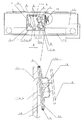
図3は第1〜4結像ミラー6〜9を筐体11設けられた結像ミラー支持部11eに固定している部分を拡大した斜視図である。図3において、6〜9は第1〜4結像ミラー、19は結像ミラーのミラー面側に設けられミラー面方向の位置を決定する突き当て面、20、21は結像ミラーの長手方向および短手方向の位置を決定するボス、22、23は結像ミラー支持部11eに設けられ、結像ミラーのボスが嵌合する丸穴および長丸穴、24は結像ミラー6〜9を結像ミラー支持部に固定するための板バネである。
【0020】
結像ミラー6〜9の位置は、その長手方向および短手方向の位置をボス20,21と長穴22、23の嵌合によって、ミラー面方向の位置を突き当て面19をミラー支持部11eに突き当てることによってそれぞれ決定され、板バネ24の押圧力によって固定される。
【0021】
結像ミラーの長手方向および短手方向の位置決め方法は本実施例に示した構成に限られるものではなく、例えば結像ミラーの側面と筐体との嵌合を用いたり、位置決め治具を用いて位置を決定した後固定したりすることも可能である。
【0022】
また、結像ミラーの固定方法は板バネの押圧力を用いる方法のほかに、例えば接着やビス止めのような方法を用いることができる。
【0023】
(第2の実施例)
図4を用いて本発明の第二の実施例について説明する。本実施例における画像読取装置の主要な構成は、第一の実施例で説明したのと同様である。
【0024】
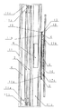
図4は図1、図2における第1〜4結像ミラー6〜9を筐体11設けられた結像ミラー支持部11eに固定している部分を拡大した斜視図である。図4において、6〜9は第1〜4結像ミラー、25は結像ミラーのミラー面側に設けられミラー面方向の位置を決定する突き当て面、26〜29は結像ミラーの長手方向および短手方向の位置を決定するボスおよび突起部、30〜33は結像ミラー支持部11eに設けられ、結像ミラーのボスおよび突起部が嵌合する長穴、34は結像ミラー6〜9を結像ミラー支持部に固定するための板バネである。
【0025】
結像ミラー6〜9の位置は、その短手方向の位置をボス26,27と長穴30,31の嵌合によって、長手方向の位置を突起部28,29と長穴32,33の嵌合によって、ミラー面方向の位置を突き当て面25をミラー支持部11eに突き当てることによってそれぞれ決定され、板バネ34の押圧力によって固定される。
【0026】
筐体11内部の温度上昇に伴って結像ミラーが膨張しても、長穴30〜33とボスおよび突起部20〜23の間には充分な隙間があるため、膨張を吸収でき、結像ミラー6〜9の反射面が変形するのを防ぐことができる。
【0027】
結像ミラーに設けたボスおよび突起部は本実施例に示した構成に限られるものではなく、例えばすべてボスとしたり、すべて突起部としたりすることも可能である。
【0028】
結像ミラーの固定方法は板バネの押圧力を用いる方法のほかに、例えば接着のような方法を用いても精度のよい固定は可能であるが、温度上昇による結像ミラーの膨張を吸収するためには本実施例で説明したような方法が望ましい。
【0029】
【発明の効果】
以上説明したように、本発明によれば、オフアキシャル反射面が形成された結像ミラーを精度良く位置決めできるとともに、キャリッジ内部が高温となった際の熱膨張を吸収できるように結像ミラーを支持できるので、キャリッジ一体走査方式においても高解像度かつ高速で原稿の画像を読み取ることが可能となった。
【図面の簡単な説明】
【図1】本発明を実施した画像読取装置の実施例における概略構成を示す断面図
【図2】図1に示した本発明の概略構成の一部を拡大した上視図
【図3】図1に示した本発明の概略構成の一部を拡大した斜視図
【図4】本発明を実施した画像読取装置の第2の実施例の構成を示す図
【図5】従来の装置の概略構成を示す図
【符号の説明】
6〜9 第1〜第4結像ミラー
10 CCD
11 筐体
19,25 突き当て面
20,21,26〜29 長手・短手方向位置決め部
22,23,30〜33 筐体に設けた嵌合部[0001]
TECHNICAL FIELD OF THE INVENTION
The present invention relates to an image reading apparatus that illuminates an original with a light source device and reads the original with a photoelectric conversion unit, and particularly relates to an imaging unit that forms an image on the photoelectric conversion unit.
[0002]
[Prior art]
2. Description of the Related Art Conventionally, an image scanner as an image reading device for reading image information on a document surface has been proposed, for example, in Japanese Patent Laid-Open Publication No. Hei 3-113396.
[0003]
Such an image scanner reads an image information by exposing and scanning an original surface by fixing only an imaging lens and a line sensor and moving only a reflection mirror.
[0004]
In recent years, in order to simplify the structure of the apparatus, a carriage-integrated scanning method for scanning a document surface by integrating a mirror, an imaging lens, a line sensor, and the like has been adopted.
[0005]
FIG. 5 shows a conventional carriage-integrated scanning type image reading apparatus. The light beam emitted from the light source 501 illuminates the document 503 placed on the document table glass 502, and the reflected light beam from the document 503 is sequentially transmitted to the inside of the carriage 511 via the first, second, and
[0006]
However, in an image reading apparatus such as a digital copying machine, high resolution and high speed are required. To improve the resolution of the imaging lens, the angle of view must be narrowed, and the optical path length increases. At the same time, the amount of light decreases. Further, when the optical path length is reduced, the angle of view becomes wider, and the resolution is reduced. Therefore, it is difficult to adopt the carriage-integrated scanning method.
[0007]
Therefore, a carriage-integrated scanning type image reading apparatus employing a non-coaxial optical system (off-axial optical system) for forming an image by reflecting a light beam as disclosed in Japanese Patent Application Laid-Open No. 8-292371, etc. It is proposed in reference number 4348009. This proposal also proposes a configuration in which chromatic aberration is not generated by using air as a medium between the reflecting surfaces of the off-axial optical system when reading a color original.
[0008]
[Problems to be solved by the invention]
However, in the above-described conventional example, no method has been proposed for positioning and fixing an image forming mirror having an off-axial reflection surface in an off-axial optical system employed in an image reading apparatus of a carriage-integrated scanning type.
[0009]
Further, in the carriage-integrated scanning method, since the lamp and the CCD serving as a heat source are disposed on or inside the carriage, a rise in the temperature inside the carriage becomes a problem. In order to perform high-quality and high-speed reading, the illuminance of the lamp and the driving speed of the CCD must be increased, so the temperature inside the carriage becomes high.However, the off-axial reflecting surface has a very accurate free-form surface shape and positioning. Therefore, it is necessary to position the imaging mirror so as to absorb the elongation of the imaging mirror so that the free-form surface shape is not deformed due to expansion when the temperature of the imaging mirror rises.
[0010]
[Means for Solving the Problems]
In order to solve the above problems, the image reading apparatus according to the first invention of the present application includes a reading unit that reads an image of a document, a lighting unit that illuminates the document, and an image of the document formed on the reading unit. An imaging unit; a housing for supporting the reading unit, the illumination unit, and the imaging unit; and a scanning unit for moving the housing to move and scan an image of a document. Is an image reading apparatus comprising a plurality of imaging mirrors each having an off-axial reflection surface having a different curvature from the incidence direction and the emission direction of the reference axis light beam, wherein the imaging mirror is positioned in the direction of the reflection surface. An abutting portion for determining the image quality is provided on the reflection surface side.
[0011]
Thus, the position of the imaging mirror in the direction of the reflection surface can be accurately determined by the tolerance in the thickness direction of the imaging mirror, as compared with the case where the abutting portion is provided and positioned on the opposite side to the reflection surface.
[0012]
Further, the image reading apparatus according to the second invention of the present application is a reading unit that reads an image of a document, an illuminating unit that illuminates the document, an imaging unit that forms an image of the document on the reading unit, and the reading unit. And a housing that supports the illumination unit and the imaging unit, and a scanning unit that moves the housing to move and scan the image of the document. In an image reading apparatus including a plurality of image forming mirrors having different emission directions and having an off-axial reflection surface having a curvature, the image forming mirrors have independent positions in a longitudinal direction and a lateral direction of the mirror. It is characterized by having a long positioning portion and a short positioning portion for determining the position, and a butting portion for determining a position in the mirror surface direction on the mirror surface side.
[0013]
Thus, the position of the imaging mirror in both the longitudinal and lateral directions can be accurately determined, and the position of the reflecting mirror in the direction of the reflecting surface is determined by providing an abutting portion on the side opposite to the reflecting surface. Only the tolerance in the thickness direction can be determined more accurately.
[0014]
Further, in the image reading device according to the third invention of the present application, the housing has a fitting portion with which a positioning portion of the imaging mirror fits, and the fitting portion is formed by the fitting portion and the longitudinal portion. And when the short positioning portion is fitted, the width is such that a gap is formed in a direction orthogonal to the fitting direction.
[0015]
Thereby, even when the inside of the carriage becomes high temperature and the imaging mirror thermally expands, the positioning portion escapes in the direction perpendicular to the fitting direction to absorb the expansion and does not break the free curved surface, so that the carriage integrated scanning is performed. Also in the system, it is possible to read the image of the original at a high resolution and at a high speed.
[0016]
BEST MODE FOR CARRYING OUT THE INVENTION
(First Embodiment)
FIG. 1 is a main cross-sectional view of an embodiment when applied to a device such as an image scanner or a copying machine that implements the image reading device of the present invention. FIG. 2 is a view of the
[0017]
In the figure,
[0018]
In this embodiment, the light beam emitted from the
[0019]
FIG. 3 is an enlarged perspective view of a portion where the first to fourth imaging mirrors 6 to 9 are fixed to the
[0020]
The positions of the
[0021]
The positioning method of the imaging mirror in the longitudinal direction and the lateral direction is not limited to the configuration shown in the present embodiment, for example, using the fitting between the side surface of the imaging mirror and the housing, or using a positioning jig. It is also possible to fix the position after determining it.
[0022]
As a method for fixing the imaging mirror, for example, a method such as bonding or screwing can be used in addition to the method using the pressing force of the leaf spring.
[0023]
(Second embodiment)
A second embodiment of the present invention will be described with reference to FIG. The main configuration of the image reading apparatus according to the present embodiment is the same as that described in the first embodiment.
[0024]
FIG. 4 is an enlarged perspective view of a portion where the first to fourth imaging mirrors 6 to 9 in FIGS. 1 and 2 are fixed to the imaging
[0025]
The positions of the imaging mirrors 6 to 9 are determined by fitting the
[0026]
Even if the imaging mirror expands as the temperature inside the
[0027]
The bosses and projections provided on the imaging mirror are not limited to the configuration shown in the present embodiment. For example, all bosses or all projections can be used.
[0028]
As a method of fixing the imaging mirror, besides the method using the pressing force of the leaf spring, for example, a method such as bonding can be used for accurate fixing, but the expansion of the imaging mirror due to a rise in temperature is absorbed. For this purpose, the method described in this embodiment is desirable.
[0029]
【The invention's effect】
As described above, according to the present invention, the imaging mirror on which the off-axial reflecting surface is formed can be accurately positioned, and the imaging mirror can be positioned so as to absorb thermal expansion when the inside of the carriage becomes hot. Because of the support, the image of the document can be read at high resolution and at high speed even in the carriage-integrated scanning method.
[Brief description of the drawings]
FIG. 1 is a cross-sectional view illustrating a schematic configuration of an image reading apparatus according to an embodiment of the present invention. FIG. 2 is an enlarged top view of a part of the schematic configuration of the present invention illustrated in FIG. FIG. 4 is an enlarged perspective view of a part of the schematic configuration of the present invention shown in FIG. 1; FIG. 4 is a diagram showing the configuration of a second embodiment of an image reading apparatus embodying the present invention; FIG. [Explanation of symbols]
6-9 First-
11
Claims (3)
前記結像ミラーは、反射面方向の位置を決定するための突き当て部を反射面側に有することを特徴とする画像読取装置。Reading means for reading an image of a document, illuminating means for illuminating the document, imaging means for forming an image of the document on the reading means, and a housing for supporting the reading means, the illuminating means and the image means Scanning means for moving the housing to move and scan the image of the document, wherein the imaging means is formed with an off-axial reflecting surface having a curvature different from the incidence direction and the emission direction of the reference axis ray. Image reading device configured by a plurality of imaging mirrors,
The image reading device according to claim 1, wherein the imaging mirror has an abutting portion for determining a position in a reflection surface direction on the reflection surface side.
前記結像ミラーは、ミラーの長手方向と短手方向の位置をそれぞれ独立に決定するための長手位置決め部および短手位置決め部を有し、かつ反射面側に反射面方向の位置を決定するための突き当て部を有することを特徴とする画像読取装置。Reading means for reading an image of a document, illuminating means for illuminating the document, imaging means for forming an image of the document on the reading means, and a housing for supporting the reading means, the illuminating means and the image means Scanning means for moving the housing to move and scan the image of the document, wherein the imaging means is formed with an off-axial reflecting surface having a curvature different from the incidence direction and the emission direction of the reference axis ray. Image reading device configured by a plurality of imaging mirrors,
The imaging mirror has a long positioning portion and a short positioning portion for independently determining the position in the longitudinal direction and the short direction of the mirror, and determines the position in the reflecting surface direction on the reflecting surface side. An image reading apparatus, comprising an abutting portion.
Priority Applications (2)
| Application Number | Priority Date | Filing Date | Title |
|---|---|---|---|
| JP2002293774A JP2004126448A (en) | 2002-10-07 | 2002-10-07 | Image reader |
| US10/674,498 US7715060B2 (en) | 2002-10-07 | 2003-10-01 | Image reading apparatus |
Applications Claiming Priority (1)
| Application Number | Priority Date | Filing Date | Title |
|---|---|---|---|
| JP2002293774A JP2004126448A (en) | 2002-10-07 | 2002-10-07 | Image reader |
Publications (2)
| Publication Number | Publication Date |
|---|---|
| JP2004126448A true JP2004126448A (en) | 2004-04-22 |
| JP2004126448A5 JP2004126448A5 (en) | 2005-10-13 |
Family
ID=32040732
Family Applications (1)
| Application Number | Title | Priority Date | Filing Date |
|---|---|---|---|
| JP2002293774A Pending JP2004126448A (en) | 2002-10-07 | 2002-10-07 | Image reader |
Country Status (2)
| Country | Link |
|---|---|
| US (1) | US7715060B2 (en) |
| JP (1) | JP2004126448A (en) |
Cited By (6)
| Publication number | Priority date | Publication date | Assignee | Title |
|---|---|---|---|---|
| JP2004354982A (en) * | 2003-05-07 | 2004-12-16 | Canon Inc | Image reader |
| JP2007334009A (en) * | 2006-06-15 | 2007-12-27 | Canon Inc | Image reader and reflecting mirror unit |
| JP2010124460A (en) * | 2008-10-23 | 2010-06-03 | Canon Inc | Image reading apparatus and image forming apparatus |
| JP2010141874A (en) * | 2008-11-13 | 2010-06-24 | Canon Inc | Image reading apparatus and image forming apparatus |
| JP2012109876A (en) * | 2010-11-18 | 2012-06-07 | Canon Inc | Image reading device and image-forming mirror |
| US8638480B2 (en) | 2009-10-06 | 2014-01-28 | Canon Kabushiki Kaisha | Image reading apparatus |
Families Citing this family (11)
| Publication number | Priority date | Publication date | Assignee | Title |
|---|---|---|---|---|
| US7292918B2 (en) | 2002-06-21 | 2007-11-06 | Intel Corporation | PC-based automobile owner's manual, diagnostics, and auto care |
| US7480082B2 (en) * | 2004-03-31 | 2009-01-20 | Carestream Health, Inc. | Radiation image scanning apparatus and method |
| JP4235608B2 (en) * | 2004-12-24 | 2009-03-11 | キヤノン株式会社 | Image reading device |
| JP2006215374A (en) * | 2005-02-04 | 2006-08-17 | Canon Inc | Imaging optical system and image reading device using the same |
| JP4182072B2 (en) * | 2005-03-02 | 2008-11-19 | キヤノン株式会社 | Image reading apparatus and image expansion / contraction correction method |
| JP4073032B2 (en) * | 2005-04-08 | 2008-04-09 | キヤノン株式会社 | Image reading apparatus and image forming apparatus |
| JP2007214948A (en) * | 2006-02-10 | 2007-08-23 | Canon Inc | Image reader |
| JP4829750B2 (en) * | 2006-11-20 | 2011-12-07 | キヤノン株式会社 | Image reading device |
| JP2008306295A (en) * | 2007-06-05 | 2008-12-18 | Canon Inc | Image reader, and image forming apparatus |
| JP5674709B2 (en) * | 2012-05-23 | 2015-02-25 | 東芝テック株式会社 | Imaging element array and image forming apparatus |
| JP2017118163A (en) | 2015-12-21 | 2017-06-29 | キヤノン株式会社 | Image reading device and image forming apparatus |
Family Cites Families (17)
| Publication number | Priority date | Publication date | Assignee | Title |
|---|---|---|---|---|
| JPH03113961A (en) | 1989-09-27 | 1991-05-15 | Canon Inc | Picture reader |
| US5589936A (en) * | 1992-09-14 | 1996-12-31 | Nikon Corporation | Optical measuring apparatus for measuring physichemical properties |
| US5844730A (en) * | 1993-04-07 | 1998-12-01 | Nikon Corporation | Light-supplying optical device |
| US5648221A (en) * | 1993-06-14 | 1997-07-15 | Nikon Corporation | Optical inspection method |
| JP3320252B2 (en) | 1995-04-24 | 2002-09-03 | キヤノン株式会社 | Reflection type optical system and imaging apparatus using the same |
| US6166866A (en) * | 1995-02-28 | 2000-12-26 | Canon Kabushiki Kaisha | Reflecting type optical system |
| KR100229024B1 (en) * | 1997-02-14 | 1999-11-01 | 윤종용 | Flatbed scanning device |
| US5883727A (en) * | 1997-05-06 | 1999-03-16 | Tsai; Shui Chuan | Multiple resolution image scanning module |
| US6608707B1 (en) * | 1997-09-12 | 2003-08-19 | Microtek International, Inc. | Scanner with removable data storage media |
| US6236472B1 (en) * | 1998-04-01 | 2001-05-22 | Mustek Systems Inc. | Flatbed scanners with single dynamic source |
| US6216952B1 (en) * | 1998-09-09 | 2001-04-17 | Dbtel Incorporated | Structure of a scanner |
| US6169622B1 (en) * | 1998-11-03 | 2001-01-02 | Mustek Systems Inc. | Optical scanner with a distance adjusting device |
| JP2002196433A (en) | 2000-12-25 | 2002-07-12 | Konica Corp | Image reading apparatus and image forming apparatus |
| JP3943952B2 (en) * | 2001-03-05 | 2007-07-11 | キヤノン株式会社 | Image reading device |
| JP4667624B2 (en) | 2001-03-14 | 2011-04-13 | 株式会社リコー | Optical scanning apparatus and image forming apparatus |
| US7149003B2 (en) * | 2001-05-15 | 2006-12-12 | Hewlett-Packard Development Company, L.P. | Bi-directional flatbed scanning and automatic document feed |
| GB0126822D0 (en) * | 2001-11-07 | 2002-01-02 | King S College London | Optical crossbar switch |
-
2002
- 2002-10-07 JP JP2002293774A patent/JP2004126448A/en active Pending
-
2003
- 2003-10-01 US US10/674,498 patent/US7715060B2/en not_active Expired - Fee Related
Cited By (9)
| Publication number | Priority date | Publication date | Assignee | Title |
|---|---|---|---|---|
| JP2004354982A (en) * | 2003-05-07 | 2004-12-16 | Canon Inc | Image reader |
| JP2007334009A (en) * | 2006-06-15 | 2007-12-27 | Canon Inc | Image reader and reflecting mirror unit |
| US9554010B2 (en) | 2006-06-15 | 2017-01-24 | Canon Kabushiki Kaisha | Image reading apparatus and reflecting mirror unit |
| JP2010124460A (en) * | 2008-10-23 | 2010-06-03 | Canon Inc | Image reading apparatus and image forming apparatus |
| US8411317B2 (en) | 2008-10-23 | 2013-04-02 | Canon Kabushiki Kaisha | Image reading apparatus and image forming apparatus capable of adjusting the difference between the spectral characteristics |
| JP2010141874A (en) * | 2008-11-13 | 2010-06-24 | Canon Inc | Image reading apparatus and image forming apparatus |
| US8503050B2 (en) | 2008-11-13 | 2013-08-06 | Canon Kabushiki Kaisha | Image reading apparatus and image forming apparatus |
| US8638480B2 (en) | 2009-10-06 | 2014-01-28 | Canon Kabushiki Kaisha | Image reading apparatus |
| JP2012109876A (en) * | 2010-11-18 | 2012-06-07 | Canon Inc | Image reading device and image-forming mirror |
Also Published As
| Publication number | Publication date |
|---|---|
| US7715060B2 (en) | 2010-05-11 |
| US20040066544A1 (en) | 2004-04-08 |
Similar Documents
| Publication | Publication Date | Title |
|---|---|---|
| JP2004126448A (en) | Image reader | |
| US7688529B2 (en) | Lens unit and image reading apparatus using the same | |
| US5566006A (en) | Image reading apparatus for selectively illuminating a first object and a second object by the same light beam and selectively detecting imaged image information therefrom | |
| US7021543B2 (en) | Image reader using off-axial optical system for imaging optical system | |
| JPH11289430A (en) | Image reader and image forming device | |
| JP3751920B2 (en) | Reading module | |
| US7440151B2 (en) | Image reading apparatus | |
| JPH0951405A (en) | Image reader | |
| JP2001255601A (en) | Image reading carriage and image reader | |
| JP2011244134A5 (en) | ||
| US8488208B2 (en) | Optical module, an image reader and an assembling method of an optical module | |
| US20050200980A1 (en) | Image scanning apparatus | |
| JP2001174932A (en) | Image reader | |
| JP4569086B2 (en) | Image reading optical apparatus and reflection surface adjusting method in the apparatus | |
| JP5725809B2 (en) | Image reading device | |
| JP2010050696A (en) | Image reading device | |
| JP2008067275A (en) | Image reader, and method of adjusting power and focus of imaging lens | |
| JP4481742B2 (en) | Image reading device | |
| JP3537080B2 (en) | Lighting equipment | |
| JP2009053323A (en) | Image reader | |
| JP2004153490A (en) | Image reading apparatus | |
| JP2004126447A (en) | Image reader | |
| JP2009010891A (en) | Image reading device | |
| JP2003295337A (en) | Image reader | |
| JP3161900B2 (en) | Image reading device |
Legal Events
| Date | Code | Title | Description |
|---|---|---|---|
| A521 | Request for written amendment filed |
Free format text: JAPANESE INTERMEDIATE CODE: A523 Effective date: 20050602 |
|
| A621 | Written request for application examination |
Free format text: JAPANESE INTERMEDIATE CODE: A621 Effective date: 20050602 |
|
| A977 | Report on retrieval |
Free format text: JAPANESE INTERMEDIATE CODE: A971007 Effective date: 20081001 |
|
| A131 | Notification of reasons for refusal |
Free format text: JAPANESE INTERMEDIATE CODE: A131 Effective date: 20081111 |
|
| A521 | Request for written amendment filed |
Free format text: JAPANESE INTERMEDIATE CODE: A523 Effective date: 20090108 |
|
| A02 | Decision of refusal |
Free format text: JAPANESE INTERMEDIATE CODE: A02 Effective date: 20090526 |