JP2004125378A - Method and device for low nox combustion - Google Patents
Method and device for low nox combustion Download PDFInfo
- Publication number
- JP2004125378A JP2004125378A JP2003141252A JP2003141252A JP2004125378A JP 2004125378 A JP2004125378 A JP 2004125378A JP 2003141252 A JP2003141252 A JP 2003141252A JP 2003141252 A JP2003141252 A JP 2003141252A JP 2004125378 A JP2004125378 A JP 2004125378A
- Authority
- JP
- Japan
- Prior art keywords
- nox
- value
- combustion
- reduction
- low
- Prior art date
- Legal status (The legal status is an assumption and is not a legal conclusion. Google has not performed a legal analysis and makes no representation as to the accuracy of the status listed.)
- Pending
Links
Images


Classifications
-
- F—MECHANICAL ENGINEERING; LIGHTING; HEATING; WEAPONS; BLASTING
- F23—COMBUSTION APPARATUS; COMBUSTION PROCESSES
- F23G—CREMATION FURNACES; CONSUMING WASTE PRODUCTS BY COMBUSTION
- F23G7/00—Incinerators or other apparatus for consuming industrial waste, e.g. chemicals
- F23G7/06—Incinerators or other apparatus for consuming industrial waste, e.g. chemicals of waste gases or noxious gases, e.g. exhaust gases
- F23G7/07—Incinerators or other apparatus for consuming industrial waste, e.g. chemicals of waste gases or noxious gases, e.g. exhaust gases in which combustion takes place in the presence of catalytic material
-
- F—MECHANICAL ENGINEERING; LIGHTING; HEATING; WEAPONS; BLASTING
- F23—COMBUSTION APPARATUS; COMBUSTION PROCESSES
- F23C—METHODS OR APPARATUS FOR COMBUSTION USING FLUID FUEL OR SOLID FUEL SUSPENDED IN A CARRIER GAS OR AIR
- F23C9/00—Combustion apparatus characterised by arrangements for returning combustion products or flue gases to the combustion chamber
- F23C9/08—Combustion apparatus characterised by arrangements for returning combustion products or flue gases to the combustion chamber for reducing temperature in combustion chamber, e.g. for protecting walls of combustion chamber
-
- F—MECHANICAL ENGINEERING; LIGHTING; HEATING; WEAPONS; BLASTING
- F23—COMBUSTION APPARATUS; COMBUSTION PROCESSES
- F23L—SUPPLYING AIR OR NON-COMBUSTIBLE LIQUIDS OR GASES TO COMBUSTION APPARATUS IN GENERAL ; VALVES OR DAMPERS SPECIALLY ADAPTED FOR CONTROLLING AIR SUPPLY OR DRAUGHT IN COMBUSTION APPARATUS; INDUCING DRAUGHT IN COMBUSTION APPARATUS; TOPS FOR CHIMNEYS OR VENTILATING SHAFTS; TERMINALS FOR FLUES
- F23L7/00—Supplying non-combustible liquids or gases, other than air, to the fire, e.g. oxygen, steam
- F23L7/002—Supplying water
-
- F—MECHANICAL ENGINEERING; LIGHTING; HEATING; WEAPONS; BLASTING
- F23—COMBUSTION APPARATUS; COMBUSTION PROCESSES
- F23C—METHODS OR APPARATUS FOR COMBUSTION USING FLUID FUEL OR SOLID FUEL SUSPENDED IN A CARRIER GAS OR AIR
- F23C2201/00—Staged combustion
- F23C2201/10—Furnace staging
- F23C2201/102—Furnace staging in horizontal direction
-
- F—MECHANICAL ENGINEERING; LIGHTING; HEATING; WEAPONS; BLASTING
- F23—COMBUSTION APPARATUS; COMBUSTION PROCESSES
- F23C—METHODS OR APPARATUS FOR COMBUSTION USING FLUID FUEL OR SOLID FUEL SUSPENDED IN A CARRIER GAS OR AIR
- F23C2201/00—Staged combustion
- F23C2201/40—Intermediate treatments between stages
- F23C2201/401—Cooling
-
- F—MECHANICAL ENGINEERING; LIGHTING; HEATING; WEAPONS; BLASTING
- F23—COMBUSTION APPARATUS; COMBUSTION PROCESSES
- F23C—METHODS OR APPARATUS FOR COMBUSTION USING FLUID FUEL OR SOLID FUEL SUSPENDED IN A CARRIER GAS OR AIR
- F23C2202/00—Fluegas recirculation
- F23C2202/10—Premixing fluegas with fuel and combustion air
-
- F—MECHANICAL ENGINEERING; LIGHTING; HEATING; WEAPONS; BLASTING
- F23—COMBUSTION APPARATUS; COMBUSTION PROCESSES
- F23C—METHODS OR APPARATUS FOR COMBUSTION USING FLUID FUEL OR SOLID FUEL SUSPENDED IN A CARRIER GAS OR AIR
- F23C2203/00—Flame cooling methods otherwise than by staging or recirculation
- F23C2203/20—Flame cooling methods otherwise than by staging or recirculation using heat absorbing device in flame
Abstract
Description
【0001】
【発明の属する技術分野】
この発明は、水管ボイラ,吸収式冷凍機の再熱器などに適用される低NOx燃焼方法とその装置に関する。
【0002】
【従来の技術】
一般に、NOxの発生の抑制原理として、▲1▼火炎(燃焼ガス)温度の抑制,▲2▼高温燃焼ガスの滞留時間の短縮,▲3▼酸素分圧を低くすることなどが知られている。そして、これらの原理を応用した種々の低NOx化技術がある。たとえば、2段燃焼法,濃淡燃焼法,排ガス再循環燃焼法,水添加燃焼法,蒸気噴射燃焼法,水管群による火炎冷却燃焼法などが提案され実用化されている。
【0003】
ところで、水管ボイラなどの比較的容量の小さいNOx発生源に対しても時代と共に排ガス規制が厳しくなり、一層の低NOx化が求められるようになってきている。出願人は、これらの要請に対する低NOx化技術を米国特許第6029614号明細書などにて提案した。
【0004】
しかしながら、これらの先行技術によるNOx低減は、現実には25ppm程度にとどまり、10ppmを下回る低NOx化技術はいまだ実用化されていない。以下、生成NOx値を10ppm以下とする低NOx化を超低NOx化という。
【0005】
その原因は、低NOx化と低CO化とが相反する技術的課題であることにある。すなわち、低NOxを推し進めるために燃焼ガス温度を急激に低下させ、900℃以下の低い温度に抑制すると、COが多量に発生すると共に発生したCOが酸化されないまま排出され、CO排出量が増大してしまう。逆に、COの排出量を少なくするために、燃焼ガス温度を高めに抑制すると、NOxの生成量の抑制が不十分となる。
【0006】
前記先行技術にて提案の低NOx化技術も、低NOx化に伴い発生するCO量をできるだけ少なくするように、また発生したCOが酸化するように燃焼ガス温度を抑制するものである。その結果、前記先行技術は、低NOx化のための手段の選択が限定され、かつ燃焼ガス温度の抑制が不十分であり、前記超低NOx化を実現するものではなかった。
【0007】
【発明が解決しようとする課題】
この発明が解決しようとする課題は、COの発生を考慮することなく低NOx化を推し進めることができると共に、排出NOx値が10ppmを下回るような低NOx化を容易に実現でき、しかも低CO化を共に実現できる低NOx燃焼方法とその装置を提供することである。
【0008】
【課題を解決するための手段】
この発明は、前記課題を解決するためになされたもので、請求項1に記載の発明は、バーナからの燃焼ガスの温度を抑制することにより低NOx化を実現する低NOx燃焼方法であって、NOx発生の抑制を排出CO値低減に優先するように燃焼ガス温度を抑制しNOx値を所定値以下とする低NOx化ステップを行い、その後に前記低NOx化ステップからの排出CO値を所定値以下とする低CO化ステップを行うことを特徴としている。
【0009】
請求項2に記載の発明は、バーナからの燃焼ガスの温度を抑制することにより低NOx化を実現する低NOx燃焼方法であって、NOx発生の抑制を排出CO値低減に優先するように燃焼ガス温度を抑制しNOx値を10ppm(排ガス0%O2換算値)以下とする低NOx化ステップを行い、その後に前記低NOx化ステップからの排出CO値を所定値以下とする低CO化ステップを行うことを特徴としている。
【0010】
請求項3に記載の発明は、バーナからの燃焼ガスの温度を抑制することにより低NOx化を実現する低NOx燃焼方法であって、NOx発生の抑制を排出CO値低減に優先するように燃焼ガス温度を抑制しNOx値を所定値以下とする低NOx化ステップを行い、その後に前記低NOx化ステップからの排出CO値を所定値以下とする低CO化ステップを燃焼ガスの温度が900℃以下の領域において行うことを特徴としている。
【0011】
請求項4に記載の発明は、請求項1〜3のいずれか1項において、前記低NOx化ステップをNOx低減目標値と前記低NOx化ステップの空気比対NOx特性とから求められる空気比にて行うことを特徴としている。
【0012】
請求項5に記載の発明は、請求項1〜3のいずれか1項において、前記低CO化ステップをCO酸化触媒体により行うことを特徴としている。
【0013】
請求項6に記載の発明は、バーナからの燃焼ガスの温度を抑制することにより低NOx化を実現する低NOx燃焼装置であって、NOx発生の抑制を排出CO値低減に優先するように燃焼ガス温度を抑制しNOx値を所定値以下とする低NOx化手段と、この低NOx化手段からの排出CO値を所定値以下とする低CO化手段とを具備することを特徴としている。
【0014】
請求項7に記載の発明は、バーナからの燃焼ガスの温度を抑制することにより低NOxを実現する低NOx燃焼装置であって、NOx発生の抑制を排出CO値低減に優先するように燃焼ガス温度を抑制しNOx値を10ppm(排ガス0%O2換算値)以下とする低NOx化手段と、この低NOx化手段からの排出CO値を所定値以下とする低CO化手段とを具備することを特徴としている。
【0015】
請求項8に記載の発明は、バーナからの燃焼ガスの温度を抑制することにより低NOx化を実現する低NOx燃焼装置であって、NOx発生の抑制を排出CO値低減に優先するように燃焼ガス温度を抑制しNOx値を所定値以下とする低NOx化手段と、この低NOx化手段からの排出CO値を燃焼ガスの温度が900℃以下の領域において所定値以下とする低CO化手段とを具備することを特徴としている。
【0016】
請求項9に記載の発明は、請求項6〜8のいずれか1項において、NOx低減目標値と前記低NOx化手段の空気比対NOx特性とから求められる空気比にて低NOx化を行うことを特徴としている。
【0017】
請求項10に記載の発明は、請求項6〜8のいずれか1項において、前記低CO化手段をCO酸化触媒体とすることを特徴としている。
【0018】
請求項11に記載の発明は、請求項6〜8のいずれか1項において、前記低NOx化手段が伝熱管除去により形成される断熱空間を有する伝熱管群から構成されることを特徴としている。
【0019】
さらに、請求項12に記載の発明は、請求項6〜8のいずれか1項において、前記低NOx化手段が伝熱管除去により形成される断熱空間を含まない伝熱管群からなることを特徴としている。
【0020】
【発明の実施の形態】
実施の形態を説明する前に、本明細書において使用する用語について説明する。燃焼ガスは、燃焼反応中(燃焼過程)の燃焼ガスと燃焼反応が完結した燃焼ガスとを含む。そして、燃焼反応中ガスは燃焼反応中の燃焼ガスを意味し、燃焼完結ガスは燃焼反応が完結した燃焼ガスを意味する。また、燃焼反応中ガスは、物質概念であるが、一般的には目視可能な火炎を含み火炎状態であるので、状態概念として火炎と称することもできる。よって、本明細書においては、燃焼反応中ガスを火炎または燃焼火炎と称する場合もある。また、排ガスとは伝熱管などによる吸熱作用を受けて温度低下した燃焼完結ガスをいう。
【0021】
また、燃焼ガス温度は、特に断らなければ、燃焼反応中ガスの温度を意味し、燃焼温度あるいは燃焼火炎温度と同義である。さらに、燃焼ガス温度の抑制とは、燃焼ガス(燃焼火炎)温度の最高値を低く抑えることを意味する。なお、通常、燃焼反応は、燃焼完結ガス中においても極微量であるが継続しているので、燃焼完結とは、燃焼反応の100%完結を意味するものではない。
【0022】
さらに、空気比は、実際燃焼空気量/理論燃焼空気量であるが、排ガスO2(%)(排ガス中の酸素濃度)と所定の関係で対応しているので、排ガスO2(%)にて表示する。また、NOx値は、排ガス0%O2換算の値を示し、CO値は、換算値でなく読取値を示す。
【0023】
つぎに、この発明の実施の形態について説明する。この発明は、小型貫流ボイラなどの水管ボイラ,給湯器,吸収式冷凍機の再熱器などの熱機器(燃焼機器と称しても良い。)に適用される。この熱機器は、バーナとこのバーナからの燃焼ガスによって加熱される吸熱体群を有する。
【0024】
この発明の方法の実施の形態は、バーナから噴出される燃焼ガスの温度を抑制することにより、低NOx化を実現する低NOx燃焼方法であって、NOx発生の抑制を排出CO値低減に優先するように燃焼ガス温度を抑制し生成NOx値を所定値以下とする低NOx化ステップを行い、その後に前記低NOx化ステップからの排出CO値を所定値以下とする低CO化ステップを行う低NOx燃焼方法である。この低NOxおよび低CO燃焼方法は、NOxが一度生成するとその後は殆ど消滅しないのに対して、COが生成後に容易に低減できるという特性に着目したものであって、まず生成NOx値が低減目標NOx値となるように低NOx化ステップを優先して実行し、その後に低CO化ステップを実行するという新規かつ有用な燃焼方法であり、低NOx化および低CO化方法である。
【0025】
まず、前記低NOx化ステップにおいて、低NOx化手段により燃焼ガス温度を抑制し、生成NOx値を所定値以下に低減する。前記所定値は、従来達成されていたNOx値以下であり、好ましくは10ppm以下である。この低NOx化においては、排出CO値の低減,すなわちCOの生成の抑制とCOの酸化の促進に優先して低NOx化を進める。この優先とは、燃焼の継続を条件に可及的に燃焼ガス温度を抑制し、まずはNOx低減化を低CO化に先だって行い、NOx低減化の後にCOの低減化を行うことを意味し、また相反する技術的課題である低NOx化と低CO化のうち低CO化を犠牲あるいは無視して低NOx化を進めることを意味する。
【0026】
前記低NOx化ステップをより具体的に説明する。前記低NOx化ステップは、前記バーナの空気比の増加に従い生成NOx値が減少する空気比対NOx特性と前記空気比の増加に従い排出CO値が増加する空気比対CO特性とを有している。前記低NOx化ステップにおいては、同ステップが有する空気比対NOx特性において、NOx値が低減目標NOx値以下となる空気比を求め、この空気比にて前記バーナを燃焼させて低NOx化を行う。この空気比を求める際には、前記低NOx化ステップが有する空気比対CO特性は考慮しない。
【0027】
ついで、前記低CO化ステップにおいて、前記低NOx化ステップにて生成され、排出されるCO値を前記低CO化手段により所定値以下とする。前記排出COの所定値は、50ppmであり、好ましくは20〜30ppmである。
【0028】
こうして、排出NOx値10ppm以下の低NOx化と排出CO値50ppm以下の低CO化とを両方とも実現できる。
【0029】
つぎに、前記低NOx化ステップおよび前記低CO化ステップの構成を説明する。
【0030】
前記低NOx化ステップは、種々の形態を含む。好ましい形態は、完全予混合式のバーナを高空気比で燃焼させることによる燃焼ガス温度の抑制手段(以下、「第一抑制手段」という。)と、吸熱体群による燃焼ガス温度の抑制手段(以下、「第二抑制手段」という。)と、燃焼完結ガスを燃焼反応領域へ再循環させることによる燃焼ガス温度の抑制手段(以下、「第三抑制手段」という。)と、前記燃焼反応領域への水添加または蒸気添加(以下、「水/蒸気添加」という。)による燃焼ガス温度の抑制手段(以下、「第四抑制手段」という。)とを組み合わせた低NOx化手段により行うステップとする。前記燃焼反応領域とは、燃焼反応中ガスが存在する領域である。
【0031】
前記第一抑制手段は、つぎの原理に基づく。前記バーナを高空気比にて燃焼させると、燃焼ガス温度が抑制され、NOx値が低減する。ここにおける高空気比とは、排ガス中に含まれるO2(%):5以上であり、好ましくは5.5以上である。この抑制作用は、前記バーナにより形成される燃焼反応領域全体にほぼ均一に作用する。
【0032】
前記第二抑制手段は、つぎの原理に基づく。前記バーナからの燃焼反応中ガス中,すなわち前記燃焼反応領域に吸熱体を多数配置して構成した吸熱体群の冷却作用により燃焼ガス温度を抑制して、NOx値を低減する。この第二抑制手段は、前記吸熱体群を配置して燃焼反応中ガスを冷却するので、不均一冷却である。そして、前記燃焼反応領域の吸熱体間の隙間においては燃焼が活発に行われている部位もある。特に、前記吸熱体の後流においては、渦流が形成されて、燃焼火炎は伝熱管により保炎される。前記吸熱体は、水管などの伝熱管にて構成されるが、これに限定されるものではない。
【0033】
燃焼反応中ガスの流れに対してどのように前記吸熱体群を配置するかの配置構成として、つぎの2つの形態を含む。その一つは、前記バーナから排ガス出口までほぼ直線状に燃焼ガスが流通する燃焼ガス通路を形成し、前記バーナからの燃焼反応中ガスと交叉するように前記吸熱体群を互いに燃焼ガスの流通を許容する間隙を存して配置する構成である。他の一つは、吸熱体群を互いに燃焼ガスの流通を許容する間隙を存して環状に配列し、前記バーナからの燃焼ガスを前記環状吸熱体群の内側から前記吸熱体群に向けて放射方向に流通させるように構成して、前記バーナからの燃焼反応中ガス中に前記吸熱体群に配置する構成である。後者の構成は、前記米国特許第6029614号明細書に示されるものと同様である。
【0034】
前記第三抑制手段は、所謂排ガス再循環燃焼法と称されるもので、前記吸熱体群による吸熱作用を受けて温度低下した後大気へ放出される排ガスの一部が、排ガス再循環通路を介して燃焼用空気に混入される。混入した排ガスの冷却効果により、燃焼ガス温度を抑制して、NOx値を低減する。この第三抑制手段は、燃焼ガスの均一冷却である。
【0035】
前記第四抑制手段は、前記燃焼反応領域への水/蒸気添加である。この水/蒸気添加により、燃焼反応中ガスが冷却され、燃焼ガス温度が抑制され、NOx値が低減する。この第四抑制手段も燃焼ガスの均一冷却である。前記水/蒸気添加は、実施に応じて前記排ガス循環通路において行うことができる。さらには、前記バーナを完全予混合式バーナとし、送風機により燃焼用空気と燃料ガスとの混合気を前記バーナへ送る実施の形態においては、前記バーナと前記送風機との間において蒸気添加を行うことができる。なお、水添加は、水を霧状として添加する。
【0036】
前記第一抑制手段〜前記第四抑制手段の組合せによる効果はつぎの通りである。個々の抑制手段の機能を単独に強化すると、各抑制手段の有する欠点が問題化してくるが、4つの抑制手段を組み合わせることで、これらの欠点を問題化することなく、比較的簡単に超低NOxを実現できる。特に、後述する前記第四抑制手段よる不安定特性を緩和して安定した低NOx化を実現できる。
【0037】
なお、前記第一抑制手段(予混合高空気比燃焼)の機能強化は、空気比を増加させることである。この機能強化により燃焼反応の停止および前記燃焼バーナの不安定燃焼が発生する。また、前記第二抑制手段(吸熱体群冷却)の機能強化は、前記伝熱管を前記バーナと接触して設けたり、吸熱体群の伝熱面密度を増加することである。この機能強化により、圧力損失が増大したり、振動燃焼などの不安定燃焼を生ずる。
【0038】
また、前記第三抑制手段(排ガス再循環)の機能強化は、排ガス再循環量を増加させることである。この機能強化により、前記第三抑制手段が有する不安定特性を増幅する。すなわち、排ガス再循環は、燃焼量の変化や負荷の変化により、排ガス流量や温度が変化する特性を有している。排ガス再循環量を増大させると、これらの不安定特性が増幅される結果、安定した低NOx化を実現できない。また、前記第三抑制手段の機能強化により、燃焼反応が抑制され、COおよび未燃分の排出増加をもたらすと共に、熱的ロスの増大を招く。また、排ガス再循環量を増大させると、送風機負荷が増加する。
【0039】
また、前記第四抑制手段(水/蒸気添加)の機能強化は、付加する水分量を増加させることである。この機能強化により、熱的ロスが増大すると共に、結露量が増加し、特に前記吸熱体へ供給する水を排ガスにより予熱する給水予熱器を有するボイラにおいては、前記給水予熱器の結露による腐食が問題となる。
【0040】
前記実施の形態によれば、前記第一抑制手段〜第四抑制手段を組み合わせているので、前記各抑制手段の機能を単独に強化することによる問題点の表面化を防止できる。
【0041】
さらに、前記実施の形態においては、好ましくは、前記空気比を所定高空気比に制御する空気比制御手段を付加する。より具体的には、排ガス中の酸素濃度を検出する酸素濃度検出手段を設け、この酸素濃度検出手段による検出酸素濃度が前記所定高空気比に対応する設定値となるように、前記バーナへ燃焼用空気を送風する送風機の回転数を制御する。前記の所定高空気比は、つぎのようにして決められる。NOx低減目標値を10ppmとすると、前記低NOx化ステップの空気比対NOx特性において前記目標値に対応する空気比を求め、こうして求めた空気比またはこの空気比以上の値を所定高空気比とする。結局、所定高空気比はNOx低減目標値に対応する。
【0042】
ここで、前記実施の形態は、つぎの変形例を含む。まず、前記低NOx化ステップを実現する低NOx化手段は、つぎの5つの変形例を含む。▲1▼前記第一抑制手段(予混合高空気比燃焼)を除き、前記第二抑制手段(吸熱体群冷却)と前記第三抑制手段(排ガス再循環)と前記第四抑制手段(水/蒸気添加)との3つの抑制手段を組み合せた形態。▲2▼前記第一抑制手段(予混合高空気比燃焼)と前記第二抑制手段(吸熱体群群冷却)と前記第三抑制手段(排ガス再循環)との3つの抑制手段を組み合せた形態。▲3▼前記第一抑制手段(予混合高空気比燃焼)と前記第二抑制手段(吸熱体群冷却)と前記第四抑制手段(水/蒸気添加)との3つの抑制手段を組み合せた形態。▲4▼前記第二抑制手段(吸熱体群冷却)と前記第三抑制手段(排ガス再循環)との2つの抑制手段を組み合せた形態。▲5▼前記第二抑制手段(吸熱体群冷却)と前記第四抑制手段(水/蒸気添加)との2つの抑制手段を組み合せた形態。
【0043】
これらの変形例の全ては、前記第二抑制手段(吸熱体群冷却)を含んでいるが、これに限定されるものではない。何故なら、この発明は、低NOx化をCO値低減に優先して行い、その後に低CO化を行うものであり、好ましい低NOx化手段はあるにしても、低NOx化手段を特定のものに限定するものではない。この実施の形態の前記低NOx化手段は、NOx低減目標を達成すべく低NOx化を進めると、排出CO値がCO低減目標値を超えてしまうものを対象としている。また、前記低NOx化手段に用いられるバーナの種類および形式についても特定のものに限定するものではない。
【0044】
また、前記空気比制御手段は、つぎの変形例を含む。前記空気比制御手段は、前記送風機の回転数を制御する構成であるが、これに代えて前記送風機の下流または上流に設けたダンパ,弁などの燃焼用空気の流量調整手段の開度を制御することによって空気比を一定に制御するように構成できる。さらに、実施に応じては、前記酸素濃度検出手段の代わりに、外気温を検出する外気温検出手段を設け、この外気温検出手段により前記送風機または前記流量調整手段を制御して、空気比を一定に制御するように構成することができる。
【0045】
ついで、前記低CO化ステップの構成につき説明する。この低CO化ステップは、前記低NOx化ステップにおいて発生し、排出されたCO値を低CO化手段により所定値以下とするステップである。
【0046】
前記低CO化ステップは、好ましくは燃焼ガスの温度が900℃以下の領域において行う。COは、燃焼ガス温度が900℃〜1400℃の範囲で、かつ必要な滞留時間を与えると、CO2に酸化することが知られている。しかしながら、この温度を維持しようとすると、低NOx化を優先して行うことに対する束縛になる。しかしながら、低CO化を燃焼ガスの温度が900℃以下の領域において行うことによりこの束縛を外すことができる。また、前記低CO化手段を選定するに際して、耐熱性の条件が緩和され、選定が容易となる。
【0047】
前記低CO化手段としては、COをCO2に酸化させるCO酸化手段を用い、好ましくはCO酸化触媒体を用いる。このCO酸化触媒体は、COの酸化だけでなく、未燃分の酸化を行う。前記CO酸化触媒体は、ボイラなどの熱機器への取付け易さ,メンテナンス性,コストの観点から好ましい手段である。
【0048】
前記CO酸化触媒体は、100℃〜1000℃で酸化触媒作用をなすものが選ばれる。下限の100℃は、前記CO酸化触媒体の活性化温度,すなわち有効な酸化触媒作用を発揮する温度であり、上限の1000℃は、前記CO酸化触媒体の耐熱性により決められる温度である。結局、前記CO酸化触媒体は、前記バーナからの燃焼ガスが流通する通路において、燃焼ガス温度が、低NOx化を優先する点から900℃以下で、前記CO酸化触媒体の活性化温度の点から100℃以上の領域に配置される。具体的な前記CO酸化触媒体の配置位置は、熱機器の缶体構造などを考慮して決定される。
【0049】
前記CO酸化触媒体は、通気性を有する基材に酸化触媒を塗布した構成とする。前記基材としては、ステンレスなどの金属,セラミックが用いられ、排ガスとの接触面積を広くするような表面処理が施される。酸化触媒としては、一般的に白金が用いられるが、実施に応じて、白金族の貴金属またはクロム,マンガン,鉄,コバルト,ニッケルなどの金属酸化物を用いることができる。
【0050】
つぎに、この発明の低NOx燃焼装置に関する実施の形態につき説明する。この発明は、前記の方法の実施の形態に対応するつぎの装置の実施の形態(1)〜(6)を含む。
【0051】
実施の形態(1):バーナからの燃焼ガスの温度を抑制することにより低NOx化を実現する低NOx燃焼装置であって、NOx発生の抑制を排出CO値低減に優先するように燃焼ガス温度を抑制し、NOx値を所定値以下とする低NOx化手段と、この低NOx化手段からの排出CO値を所定値以下とする低CO化手段とを具備する低NOx燃焼装置。
【0052】
実施の形態(2):バーナからの燃焼ガスの温度を抑制することにより低NOx化を実現する低NOx燃焼装置であって、燃焼ガス温度の抑制により燃焼完結ガス中のNOx値を10ppm以下とする低NOx化手段と、この低NOx化手段からの排出CO値を所定値以下とする低CO化手段とを具備する低NOx燃焼装置。
【0053】
実施の形態(3):完全予混合式のバーナを高空気比で燃焼させることによる燃焼ガス温度の抑制手段と、吸熱体群による燃焼ガス温度の抑制手段と、燃焼完結ガスを燃焼ガスの燃焼反応領域へ再循環させることによる燃焼ガス温度の抑制手段と、前記燃焼反応領域への水添加または蒸気添加による燃焼ガスの抑制手段とを組み合わせて行う低NOx化手段と、この低NOx化手段からの排出COを酸化させてCO値を所定値以下とする低CO化手段とを具備する低NOx燃焼装置。
【0054】
実施の形態(4):バーナからの燃焼ガスの温度を抑制することにより低NOx化を実現する低NOx燃焼装置であって、NOx発生の抑制を排出CO値低減に優先するように燃焼ガス温度を抑制し、NOx値を所定値以下とする低NOx化手段と、この低NOx化手段からの排出CO値を燃焼ガスの温度が900℃以下の領域において所定値以下とする低CO化手段とを具備する低NOx燃焼装置。
【0055】
実施の形態(5):バーナからの燃焼ガスの温度を抑制することにより低NOx化を実現する低NOx燃焼装置であって、空気比対NOx特性が前記バーナの空気比の増加に従い生成NOx値が減少するものであり、空気比対CO特性が前記空気比の増加に従い排出CO値が増加するものである低NOx化手段と、前記低NOx化手段からの排出CO値を所定値以下とする低CO化手段とを具備し、NOx低減目標値と前記空気比対NOx特性とから求められる空気比にて前記バーナを燃焼させることにより低NOx化を行う低NOx燃焼装置。
【0056】
実施の形態(6):前記実施の形態(1)〜(5)のいずれかにおいて、低CO化手段が、CO酸化触媒体である低NOx燃焼装置。
【0057】
さらに、前記装置に関する実施の形態は、さらにつぎの実施の形態(7)〜(9)を含む。
【0058】
実施の形態(7):バーナからの燃焼ガスの温度を制御することにより低NOx化を実現する低NOx燃焼装置であって、空気比対NOx特性が前記バーナの空気比の増加に従い生成NOx値が減少するものであり、空気比対CO特性が前記空気比の増加に従い排出CO値が増加するものである低NOx化手段と、前記バーナの空気比を所定高空気比に制御する空気比制御手段と、前記低NOx化手段からの排出CO値を所定値以下とする低CO化手段とを具備した低NOx燃焼装置。
【0059】
実施の形態(8):前記実施の形態(7)において、前記所定空気比がNOx低減目標値と前記空気比対NOx特性とから求められる低NOx燃焼装置。
【0060】
実施の形態(9):前記実施の形態(7)〜(8)のいずれかにおいて、低CO化手段が、CO酸化触媒体であることを特徴とする低NOxおよび低CO燃焼装置。
【0061】
前記実施の形態(3)においては、前記低NOx化手段を前記第一抑制手段〜第四抑制手段の組合せにより実現させるよう構成しているが、実施に応じては、前記低NOx化手段をこの組合せ以外の前記の方法の実施の形態において説明した5つの変形例とすることもできる。前記空気比制御手段は、前記の装置における実施の形態で説明したものと同様である。
【0062】
前記実施の形態(1)〜(9)によれば、低NOxと低COとを両方共に実現できると共に、実施の形態(7)〜(8)によれば、外気温が変動しても空気比の一定制御により安定した低NOx化を実現できる。
【0063】
また、前記の実施の形態において、前記低NOx化ステップに、低CO化手段による低NOx化を含ませ、前記低NOx化手段に低CO化手段を含ませることができる。この低CO化手段は、吸熱体群中に形成したCO酸化のための吸熱体除去空間(すなわち、CO酸化空間)である。前記のように、COは、燃焼ガス温度が900℃〜1400℃の温度範囲で、かつ必要な滞留時間を与えると、CO2に酸化する。前記空間は、この原理を応用するものであり、吸熱体を複数本除去して形成され、燃焼ガス温度がある燃焼条件において前記温度範囲となるよう構成した空間である。
【0064】
【実施例】
この発明の低NOx燃焼方法とその装置を水管ボイラの一種である貫流式の蒸気ボイラに適用した実施例について、以下に図面に従い説明する。図1は、この発明の一実施例を適用した蒸気ボイラの縦断面の説明図であり、図2は、図1のII−II線に沿う断面図であり、図3は、図1のIII−III線に沿う横断面図であり、図4および図5は、それぞれ図1に示す実施例における高燃焼時,低燃焼時の空気比対NOx特性および空気比対CO特性を示す図であり、図6は、図1に示す実施例の要部制御回路図であり、図7は、図1に示す実施例のCO酸化触媒体を排ガスの流れ方向から見た要部構成を示す図である。
【0065】
以下に、この実施例のボイラの全体構成を説明し、ついで特徴部分の構成につき説明する。特徴部分とは、完全予混合式のバーナを高空気比で燃焼させることによる燃焼ガス温度の抑制手段(第一抑制手段),多数の伝熱管による燃焼ガス温度の抑制手段(第二抑制手段),燃焼完結ガスを燃焼反応領域へ再循環させることによる燃焼ガス温度の抑制手段(第三抑制手段)および前記燃焼反応領域への蒸気添加による燃焼ガス温度の抑制手段(第四抑制手段)を組み合わせて行う低NOx化手段と、前記バーナの空気比を所定の高空気比に維持すべく制御する空気比制御手段と、前記低NOx化手段から排出されるCOを酸化させて排出CO値を所定値以下とする低CO化手段である。
【0066】
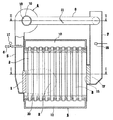
まず、前記蒸気ボイラの全体構成につき説明する。この蒸気ボイラは、高燃焼と低燃焼とを切替えて運転できる。そして、平面状の燃焼面(予混合気の噴出面)を有する完全予混合式のバーナ1および多数の熱吸収用の伝熱管2,2,・・・を有する缶体3と、前記バーナ1へ燃焼用空気を送る送風機4および給気通路5と、ガス燃料供給管6と、前記缶体3から排出される排ガスを排出する排ガス通路(通常「煙突」と称される。)7と、この排ガス通路7を流通するの排ガスの一部を燃焼用空気へ混入させて前記バーナ1へ供給する排ガス再循環通路8と、燃焼用空気へ蒸気を添加する蒸気添加管9(図3参照)とを備えている。なお、前記各伝熱管2の外径は、60.5mmである。
【0067】
前記缶体3は、上部管寄せ10および下部管寄せ11を備え、この両管寄せ10,11間に複数の前記各伝熱管2を配置している。図2において、前記缶体3の長手方向の両側部に外側伝熱管12,12,・・・を連結部材13,13・・・で連結して構成した一対の水管壁14,14を設け、この両水管壁14,14と前記上部管寄せ10および下管寄せ11との間に前記バーナ1からの燃焼反応中ガスおよび燃焼完結ガスがほぼ直線的に流通する燃焼ガス通路15を形成している。
【0068】
つぎに、前記各要素間の接続関係を説明する。図1に示すように、前記燃焼ガス通路15の一端には前記バーナ1が設けられ、他端の排ガス出口16には排ガス通路7が接続されている。前記バーナ1には前記給気通路5が接続され、前記給気通路5には前記ガス燃料供給管6が燃料ガスを前記給気通路5内へ噴出するように接続されている。前記ガス燃料供給管6には、高燃焼と低燃焼とで燃料流量を調整する燃料流量調整手段としての第一弁17を備えている。なお、前記給気通路5には、前記燃料ガスと燃焼用空気との混合性を良くするためのベンチュリーと称される絞り部(図示しない)を設けているが、圧損を減じるために実施に応じて、省略できる。
【0069】
さらに、図3に示すように、前記送風機4の吸込口18には吸気通路19が接続され、この吸気通路19と前記排ガス通路7との間に前記排ガス再循環通路8が接続されている。前記吸気通路19内には、前記蒸気添加管9が挿入されている。
【0070】
以上の構成に基づく、前記蒸気ボイラの概略動作は、以下の通りである。前記吸気通路19から供給される燃焼用空気(外気)は、前記ガス燃料供給管6から供給される燃料ガスと前記給気通路5内において予混合され、この予混合気は前記バーナ1から前記缶体3内へ向けて噴出される。予混合気は、着火手段(図示しない)により着火され、燃焼する。この燃焼に伴い生ずる燃焼反応中ガスは、上流側の伝熱管2群と交叉して冷却された後、燃焼完結ガスとなり下流側の伝熱管2群と熱交換して吸熱されて排ガスとなる。この排ガスは、前記排ガス通路7から大気中へ排出される。そして、排ガスの一部は、前記排ガス再循環通路8を経て前記バーナ1へ供給され、燃焼ガス温度の抑制に用いられる。
【0071】
また、前記各伝熱管2中の水は、燃焼ガスとの熱交換により加熱され、蒸気化される。この蒸気は、前記上部管寄せ10に接続される蒸気取出手段(図示しない)から蒸気使用設備(図示しない)へ供給されると共に、その一部が前記蒸気添加管9へ供給され、燃焼反応中ガスの冷却に用いられる。
【0072】
つぎに、この実施例の前記特徴部分につき説明する。まず、前記低NOx化手段の前記第一抑制手段につき説明する。この第一抑制手段は、前記完全予混合式のバーナ1を高空気比で燃焼させる構成である。前記バーナ1を高空気比にて燃焼させると、燃焼ガス温度が抑制され、NOx値が低下する。前記バーナ1は、大きさ縦60cm,横18cmの矩形状のバーナであり、多数の予混合気噴出口(図示しない)がほぼ均等に形成されている。
【0073】
前記第二抑制手段は、多数の前記伝熱管2を前記バーナ1により形成される燃焼反応領域(燃焼ガス温度が約900℃以上の領域)20のほぼ全域に互いに燃焼ガスが流通する間隙を存して配設した構成である。前記バーナ1からの燃焼反応中ガスは、これら伝熱管2群により冷却される。この冷却により、燃焼ガス温度が抑制され、NOx値が下がる。燃焼ガスの冷却度合いに影響を与える前記伝熱管2群の配列ピッチは、時間当りの燃焼量および圧損などを考慮して決めている。
【0074】
前記第三抑制手段は、前記排ガス通路7と前記排ガス再循環通路8と前記給気通路5と前記バーナ1とから構成される排ガス再循環手段である。前記排ガス再循環通路8内の適所には、再循環される排ガス量(排ガス再循環量)を所定量に調整する排ガス流量調整手段としての第一ダンパ21を設けている。前記バーナ1へ供給される予混合気に排ガスを混入させることで、燃焼ガス温度が抑制され、NOx値が下がる。排ガス再循環量と燃焼用空気量(実際燃焼空気量)との比率は、前記第一ダンパ21により調整される。
【0075】
前記第四抑制手段は、図3に示すように、前記蒸気添加管9と前記吸気通路19と前記送風機4と前記給気通路5と前記バーナ1とから構成される。この蒸気添加管9の上流端は、蒸気添加量を調整する蒸気流量調整手段としての第二弁22を介して前記上部管寄せ10に接続され、前記蒸気ボイラにて生成される蒸気がそのまま利用されるよう構成されている。前記第二弁22と前記上部管寄せ10との間にはオリフィスなどの減圧機構(図示しない)を設ける。蒸気は、前記バーナ1へ供給される燃焼用空気に均一に混入され、前記バーナ1の多数の予混合気噴出口(図示しない)からほぼ均一に前記缶体3内へ噴出される。その結果、広がって形成される予混合燃焼火炎に対し効果的な冷却がなされる。
【0076】
この実施例の蒸気ボイラは、前記のように、高燃焼と低燃焼とを切替えて行うことができる。そして、この蒸気ボイラの前記低NOx化手段は、図4および図5に示す高燃焼時と低燃焼時の空気比対NOx特性および空気比対CO特性を有する。この空気比対NOx特性および空気比対CO特性について以下に説明する。
【0077】
まず、高燃焼時の空気比対NOx特性および空気比対CO特性は、ある運転条件にて空気比を変化させることでそれぞれ図4の曲線Aおよび曲線Bのように求められる。前記運転条件は、燃料がLPGであり、前記バーナ1の燃焼量が50Nm3/h(前記蒸気ボイラの高燃焼時の燃焼量)であり、排ガス再循環率が4%(排ガス再循環量/実際燃焼空気量)であり、蒸気添加量が17kg/hである。そして、排ガス再循環率4%における実際燃焼空気量および排ガス再循環量は、たとえばO2(%):6において、それぞれ1669Nm3/h,67Nm3/hとなる。
【0078】
空気比の変化は、実際燃焼空気量を変化させることで行われる。この実際燃焼空気量の変化は、前記送風機4のファン23を駆動する電動機24(図3参照)の回転数を制御することにより行われる。
【0079】
この高燃焼時の低NOx化手段の空気比対NOx特性は、曲線Aに示すように、空気比の増加に対してNOx値が減少するものとなっている。また、空気比対CO特性は、曲線Bに示すように、空気比の増加に従い排出CO値が増加し、特に、O2(%):5以上で急激に排出CO値が増加するものとなっている。なお、図4の曲線Cおよび曲線Dは、前記第三抑制手段および第四抑制手段による燃焼ガス温度の抑制を行わない対比例の空気比対NOx特性および空気比対CO特性であって、この実施例の曲線Aおよび曲線Bと対比するためのものである。
【0080】
つぎに、低燃焼時の低NOx化手段の空気比対NOx特性および空気比対CO特性について説明する。これらの特性は、高燃焼時のものと同様にそれぞれ図5の曲線Eおよび曲線Fのように求められる。低燃焼時の運転条件は、燃料がLPGであり、前記バーナの燃焼量が25Nm3/h(前記蒸気ボイラの低燃焼時の燃焼量)であり、排ガス再循環率が4%(排ガス再循環量/実際燃焼空気量)であり、蒸気添加量が8.5kg/hである。そして、排ガス再循環率4%における実際燃焼空気量および排ガス再循環量は、たとえばO2(%):6において、それぞれ834Nm3/h,33Nm3/hとなる。
【0081】
この低燃焼時の低NOx化手段の空気比対NOx特性も、曲線Eに示すように、空気比の増加に対してNOx値が減少するものとなっている。また、空気比対CO値特性は、曲線Fに示すように空気比の増加に従い排出CO値が増加し、特にO2(%):5.5以上で急激に排出CO値が増加するものとなっている。なお、図5の曲線Gおよび曲線Hは、前記第三抑制手段および第四抑制手段による燃焼ガス温度の抑制を行わない対比例の空気比対NOx特性および空気比対CO特性であって、この実施例の曲線Eおよび曲線Fと対比するためのものである。
【0082】
前記空気比制御手段は、図6に示すように、前記排ガス通路7に設けた前記酸素濃度検出手段としての酸素濃度センサ25と、この酸素濃度センサ25の出力を入力して、前記電動機24の回転数を制御する制御回路26とから構成される。前記電動機24は、インバータ制御による回転数制御可能なように構成される。前記ファン23の回転数を前記バーナ1の空気比が所定の高空気比(所定値)となるように制御することで、外気温の変化に対して所定の低NOx効果を維持する。
【0083】
この実施例においては、前記所定値は、NOx低減目標値を10ppmとした場合、高燃焼時は図4の曲線Aと10ppmとから、O2(%):5.8として求められる。勿論、5.8%以上であれば、低減目標値をクリアできるので、前記所定値を,たとえば6%とすることもできる。低燃焼時は、図5の曲線Eと10ppmとから、O2(%):6.25として求められる。
【0084】
ついで、前記低CO化手段につき説明する。この低CO化手段は、前記低NOx化手段から排出されるCOを酸化し、CO低減目標値以下に低減するものである。前記低CO化手段は、前記伝熱管2群の後流に配置される。
【0085】
この実施例における低CO化手段は、CO値を約1/10に低減するCO酸化触媒体27にて構成される。このCO酸化触媒体27によるCO低減特性は、図4の曲線Mおよび図5の曲線Nにて示される。結局、曲線Dおよび曲線Eにて示される排ガス中のCOは、曲線Mおよび曲線Nのように低減される。
【0086】
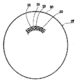
このCO酸化触媒体27は、図7に示すような構造のもので、たとえば,つぎのようにして形成される。前記基材としての共にステンレス製の平板28および波板29のそれぞれの表面に多数の微小凹凸を形成し、その表面に酸化触媒を塗布する。ついで、所定幅の前記平板28および波板29を重ね合わせたうえで、螺旋状に巻回してロール状に形成している。このロール状のものを側板30にて包囲し固定している。こうして図7に示すような前記CO酸化触媒体27が形成される。前記酸化触媒としては、白金を用いている。なお、図7においては、前記平板28および前記波板29の一部のみを示している。
【0087】
前記CO酸化触媒体27は、図1に示すように、前記排ガス出口16部に着脱自在に装着される。前記排ガス出口16部における燃焼ガス温度は、約250℃〜350℃である。前記CO酸化触媒体27の大きさおよび処理容量は、酸化触媒の性能と、酸化させるべきCOの量と、前記CO酸化触媒体27を排ガスが流通するときに生ずる圧力損失とを考慮して設計している。
【0088】
さらに、前記低NOx化手段は、図2に示すように、前記CO酸化触媒体27と別の低CO化手段を含んでいる。この低CO化手段は、伝熱管2群中に形成される断熱空間と称される伝熱管除去空間31である。そして、図2に示すように、前記伝熱管2群の一部(この実施例では4本の前記伝熱管2)を除去して燃焼ガス温度が1400℃以下で、900℃以上の温度範囲となる前記伝熱管除去空間31を形成している。
【0089】
前記伝熱管除去空間31は、高燃焼時に、ほぼ前記温度範囲となるが、低燃焼時には燃焼火炎が短い,すなわち燃焼反応領域が狭くなるので、前記温度範囲に入らなくなる。したがって、高燃焼時は、前記CO酸化触媒体27と前記伝熱管除去空間31が低CO化手段として機能し、低燃焼時は、前記伝熱管除去空間31は低CO化手段として機能せず、前記CO酸化触媒体27が低CO化手段として機能する。
【0090】
前記構成の実施例の動作および作用を以下に説明する。前記バーナ1からの燃焼反応中ガスは、低NOx化作用,すなわち前記の第一抑制手段〜第四抑制手段による燃焼ガス温度抑制作用を同時に受け、しかも前記空気比制御手段によりO2(%)を高燃焼時5.8,低燃焼時6.25とする定空気比制御を受ける。この実施例の燃焼ガス温度抑制作用により、燃焼ガス温度は、前記第三抑制手段および第四抑制手段の作用を受けない前記対比例と比較して、約100℃程度平均的に低下する。その結果、上流側伝熱管2群から流出する燃焼ガス中のNOx値は、図4および図5の曲線Aおよび曲線Eに示すように、10ppm程度に抑制される。
【0091】
前記の低NOx化の際に生成されるCOは、つぎのようにして低減化される。生成されたCOは、高燃焼時においてはまず伝熱管除去空間31にてその一部が酸化され、低燃焼時にはほとんど酸化されない。このCOの酸化は、燃焼ガス温度が900℃以下では、ほとんど行われないので、前記排ガス出口16における排ガス中のCO値は、図4および図5の特性曲線Bおよび曲線Fに示されるように、高燃焼時は約400ppmで、また低燃焼時は約100ppm程度となる。この排ガス中に残存するCOは、前記CO酸化触媒体27により酸化され、図4および図5の特性曲線Mおよび曲線Nに示されるように、CO値が約1/10に低減される。
【0092】
この実施例によれば、つぎの作用効果を奏する。低NOx化を優先して行い、その後に低CO化を行うので、CO値を考慮することなく、低NOx化を推進でき、低NOx化手段の選択が容易となる。その結果、生成NOx値を10ppm以下とする低NOx化を容易に実現でき、しかも低CO化を確実に実現できる。
【0093】
また、前記空気比制御手段により空気比をほぼ一定の高空気比に制御するので、外気温が変動しても安定した低NOx効果を得ることができる。その結果、1日および年間の広範な運転点においてNOx低減目標値をクリアできる。
【0094】
また、前記定空気比制御により、前記低NOx化手段からの排出のCO値も一定に制御される。その結果、空気比変動により排出CO値が増加して、前記CO酸化触媒体27の処理能力を超えるということがなくなり、安定した低CO化をも実現できる効果を奏する。特に、NOx低減目標値を10ppm以下とするような低NOx化手段においては、10ppm近傍では、排出CO値が急激に増加するので、定空気比制御は、CO低減目標値の達成および前記CO酸化触媒体27の容量の設計を容易にする点においてに非常に効果が大きい。
【0095】
前記CO酸化触媒体27の容量の設計を容易にする点について、さらに説明する。前記CO酸化触媒体27は、容量を大きくすると圧力損失が増加するので、CO低減目標値をぎりぎりでクリアできるように設計される。定空気比制御を行わないと、前記CO酸化触媒体27の処理容量を余裕をもって設計する必要が生ずる。また、処理容量を大きくすると、圧力損失が増大する。その結果、前記蒸気ボイラ自体の圧力損失が増大し、前記送風機4や前記缶体3を設計し直す必要が生ずる。この実施例のように、定空気比制御を行うことで、これらの問題を解決できる効果を奏する。
【0096】
さらに、低燃焼時は、前記伝熱管除去空間31は低CO化手段として有効に機能しないが、前記CO酸化触媒体27によりCOが酸化されるので、高燃焼時,低燃焼時に拘わらず、低CO化を実現できる。
【0097】
なお、この発明は前記実施例に限定されるものではなく、つぎの変形例を含む。前記実施例においては、前記第一抑制手段を完全予混合式のバーナとしているが、実施に応じて部分予混合式のバーナとすることができる。
【0098】
また、前記実施例においては、前記第二抑制手段の前記各伝熱管2を垂直水管により構成しているが、水平あるいは傾斜して配置される水管により構成することができる。さらに、前記各伝熱管2の形状も前記実施例の真円に限定されるものではなく、実施に応じて楕円などの形状とすることができる。
【0099】
また、前記実施例においては、前記第二抑制手段の前記各伝熱管2を裸管としているが、実施に応じて、前記伝熱管除去空間31の下流の前記各伝熱管2に水平のヒレ状フィンや全周フィン(いずれも図示しない)を取り付けて、熱回収率を向上させるようにすることができる。
【0100】
また、前記実施例においては、前記第四抑制手段の前記蒸気添加管9の蒸気を前記吸気通路19中へ噴出するように構成しているが、実施に応じて、図8に示すように、前記蒸気添加管9を前記バーナ1と前記送風機4との間に蒸気を噴出するように取り付けることができる。この変形例によれば、前記送風機4の下流側にて蒸気を供給しているので、上流側にて供給する前記実施例と比較して、前記送風機4の送風負荷の増大を少なくできると共に、結露による前記送風機4の腐食を防止できる。
【0101】
また、実施に応じて、図9に示すように、前記蒸気添加管9を前記排ガス再循環通路8に蒸気を噴出するように取り付けることができる。蒸気を前記排ガス再循環通路8に噴出させることにより、結露がしにくくなり、錆の発生を少なくできると共に、蒸気と燃焼用空気との混合の均一化がなされるなどの効果を発揮する。
【0102】
また、前記実施例においては、前記空気比制御手段を前記送風機4の回転数を制御するように構成しているが、実施に応じて、図10に示すように、前記送風機4の下流側に設けた燃焼用空気流量調整手段としての第二ダンパ32により空気比を制御するように構成できる。
【0103】
また、前記実施例においては、前記空気比制御手段を前記酸素濃度センサ25の信号により制御するものとしているが、実施に応じて、前記送風機4の吸気温度を検出する前記外気温検出手段としての外気温センサ33を設け、図11に示すように、この外気温センサ33出力により、空気比を制御するように構成することができる。この場合、所定燃焼量および所定排ガス再循環量において、外気温と空気比との関係を実験にて予め求め、外気温対送風機回転数の対比テーブル(図示しない)を作成する。そして、この対比テーブルを制御回路34のメモリ(図示しない)に記憶させておき、このテーブルに基づき空気比がほぼ一定となるように、前記送風機4の前記電動機24を制御するように構成することができる。
【0104】
また、前記実施例においては、前記低NOx化手段に前記伝熱管除去空間31を含ませているが、実施に応じて、図12に示すように、前記伝熱管除去空間31を省略する,すなわち前記伝熱管2を除去しないよう構成することができる。
【0105】
また、前記実施例の蒸気ボイラは、燃焼量を高燃焼と低燃焼とに切替え可能なように構成しているが、実施に応じて、燃焼量の切替の無い蒸気ボイラとすることもできる。
【0106】
さらに、前記実施例においては、前記CO酸化触媒体27を前記排ガス出口16部に取り付けているが、給水予熱器(エコノマイザ)を前記排ガス通路7に設けるものおいては、前記給水予熱器を収容する室において前記給水予熱器の上流側に配置することができる。
【0107】
【発明の効果】
この発明によれば、COの発生を考慮することなく低NOx化を推し進めることができると共に、排出NOx値が10ppmを下回るような低NOx化を容易に実現でき、しかも低CO化を共に実現でき、時代のニーズに適応した低公害型の技術および商品を提供できるものであり、産業的価値は多大である。
【図面の簡単な説明】
【図1】この発明の一実施例を適用した蒸気ボイラの縦断面の説明図である。
【図2】同実施例の図1のII−II線に沿う断面説明図である。
【図3】同実施例の図1のIII−III線に沿う横断面説明図である。
【図4】同実施例の図1に示す蒸気ボイラの高燃焼時の空気比対NOx特性および空気比対CO特性曲線を示す図である。
【図5】同実施例の図1に示す蒸気ボイラの低燃焼時の空気比対NOx特性および空気比対CO特性曲線を示す図である。
【図6】同実施例の図1に示す蒸気ボイラの要部制御回路図である。
【図7】同実施例の図1に示す蒸気ボイラのCO酸化触媒体の要部構成を示す正面図である。
【図8】この発明の他の実施例の第四抑制手段を備えた蒸気ボイラの縦断面の説明図である。
【図9】この発明の他の実施例の第四抑制手段を備えた蒸気ボイラの縦断面の説明図である。
【図10】この発明の他の実施例の空気比制御手段を備えた蒸気ボイラの縦断面の説明図である。
【図11】この発明の他の実施例の空気比制御手段の要部制御回路図である。
【図12】この発明の他の実施例の図2に相当する断面説明図である。
【符号の説明】
1 バーナ
2 伝熱管
3 缶体
4 送風機
7 排ガス通路
8 排ガス再循環通路
9 蒸気添加管
27 酸化触媒体
31 伝熱管除去空間[0001]
TECHNICAL FIELD OF THE INVENTION
The present invention relates to a low NOx combustion method applied to a water tube boiler, a reheater of an absorption refrigerator, and the like, and an apparatus therefor.
[0002]
[Prior art]
In general, it is known that the principle of suppressing the generation of NOx is (1) suppression of flame (combustion gas) temperature, (2) reduction of residence time of high-temperature combustion gas, and (3) reduction of oxygen partial pressure. . There are various NOx reduction technologies that apply these principles. For example, a two-stage combustion method, a concentration combustion method, an exhaust gas recirculation combustion method, a water addition combustion method, a steam injection combustion method, a flame cooling combustion method using a water pipe group, and the like have been proposed and put into practical use.
[0003]
By the way, with the times, exhaust gas regulations have become stricter even for relatively small-capacity NOx generation sources such as water tube boilers, and further reduction in NOx has been demanded. The applicant has proposed a technology for reducing NOx in response to these requests, for example, in US Pat. No. 6,029,614.
[0004]
However, the reduction of NOx by these prior arts is actually only about 25 ppm, and the NOx reduction technology of less than 10 ppm has not yet been put to practical use. Hereinafter, the reduction of NOx at which the generated NOx value is 10 ppm or less is referred to as ultra-low NOx reduction.
[0005]
The cause is that reduction of NOx and reduction of CO are contradictory technical problems. That is, if the temperature of the combustion gas is rapidly reduced to promote low NOx and suppressed to a low temperature of 900 ° C. or less, a large amount of CO is generated and the generated CO is discharged without being oxidized, thereby increasing the amount of CO emission. Would. Conversely, if the combustion gas temperature is suppressed to a higher value in order to reduce the amount of CO emission, the suppression of the NOx generation amount will be insufficient.
[0006]
The NOx reduction technology proposed in the prior art also suppresses the combustion gas temperature so that the amount of CO generated due to the reduction of NOx is reduced as much as possible and the generated CO is oxidized. As a result, in the prior art, the selection of the means for reducing NOx is limited, and the suppression of the combustion gas temperature is insufficient, so that the ultralow NOx is not realized.
[0007]
[Problems to be solved by the invention]
The problem to be solved by the present invention is to reduce NOx without considering generation of CO, and to easily realize reduction of NOx such that the emission NOx value is less than 10 ppm, and furthermore to reduce CO. Is to provide a low NOx combustion method and apparatus capable of realizing both.
[0008]
[Means for Solving the Problems]
The present invention has been made to solve the above-mentioned problem, and the invention according to
[0009]
The invention according to
[0010]
The invention according to
[0011]
According to a fourth aspect of the present invention, in the method of any one of the first to third aspects, the NOx reduction step is performed based on a NOx reduction target value and an air ratio obtained from an air ratio-to-NOx characteristic of the NOx reduction step. It is characterized by performing.
[0012]
According to a fifth aspect of the present invention, in any one of the first to third aspects, the CO reduction step is performed using a CO oxidation catalyst.
[0013]
The invention described in
[0014]
An invention according to
[0015]
The invention according to
[0016]
According to a ninth aspect of the present invention, in any one of the sixth to eighth aspects, the NOx reduction is performed at an air ratio obtained from a NOx reduction target value and an air ratio-to-NOx characteristic of the NOx reduction means. It is characterized by:
[0017]
According to a tenth aspect of the present invention, in any one of the sixth to eighth aspects, the CO reduction means is a CO oxidation catalyst.
[0018]
According to an eleventh aspect of the present invention, in any one of the sixth to eighth aspects, the NOx reduction unit includes a heat transfer tube group having a heat insulating space formed by removing the heat transfer tube. .
[0019]
Further, the invention according to
[0020]
BEST MODE FOR CARRYING OUT THE INVENTION
Before describing the embodiments, terms used in the present specification will be described. The combustion gas includes the combustion gas during the combustion reaction (combustion process) and the combustion gas after the completion of the combustion reaction. The combustion reaction gas means the combustion gas during the combustion reaction, and the combustion complete gas means the combustion gas after the combustion reaction has been completed. Further, the gas during the combustion reaction is a substance concept, but is generally in a flame state including a visible flame, and thus can be referred to as a flame as a state concept. Therefore, in this specification, the gas during the combustion reaction may be referred to as a flame or a combustion flame. Further, the exhaust gas refers to a combustion complete gas whose temperature has been reduced by an endothermic effect of a heat transfer tube or the like.
[0021]
Unless otherwise specified, the combustion gas temperature means the temperature of the gas during the combustion reaction, and is synonymous with the combustion temperature or the combustion flame temperature. Further, suppressing the combustion gas temperature means suppressing the maximum value of the combustion gas (combustion flame) temperature to a low value. Normally, the combustion reaction continues even though the amount is very small even in the combustion complete gas. Therefore, the completion of combustion does not mean 100% completion of the combustion reaction.
[0022]
Furthermore, the air ratio is the actual combustion air quantity / theoretical amount of combustion air, exhaust gas O 2 (%) so are supported by a predetermined relationship (oxygen concentration in the exhaust gas), the exhaust gas O 2 (%) To display. The NOx value indicates a value in terms of 0% O 2 in exhaust gas, and the CO value indicates a read value instead of a converted value.
[0023]
Next, an embodiment of the present invention will be described. INDUSTRIAL APPLICABILITY The present invention is applied to heat appliances (may be referred to as combustion appliances) such as a water tube boiler such as a small once-through boiler, a water heater, and a reheater of an absorption refrigerator. The thermal device has a burner and a group of heat absorbers heated by combustion gas from the burner.
[0024]
An embodiment of the method of the present invention is a low NOx combustion method for realizing low NOx reduction by suppressing the temperature of combustion gas ejected from a burner, and giving priority to reduction of NOx generation to reduction of emission CO value. To perform a low NOx reduction step of suppressing the combustion gas temperature and reducing the generated NOx value to a predetermined value or less, and thereafter performing a low CO reduction step of reducing the emission CO value from the NOx reduction step to a predetermined value or less. This is a NOx combustion method. This low-NOx and low-CO combustion method focuses on the characteristic that once NOx is generated, it hardly disappears thereafter, but CO can be easily reduced after it is generated. This is a new and useful combustion method in which the step of lowering the NOx is executed preferentially so as to obtain the NOx value, and then the step of lowering the CO is executed.
[0025]
First, in the NOx reduction step, the combustion gas temperature is suppressed by the NOx reduction means, and the generated NOx value is reduced to a predetermined value or less. The predetermined value is equal to or less than a conventionally achieved NOx value, and preferably equal to or less than 10 ppm. In this NOx reduction, the NOx reduction is promoted in preference to the reduction of the exhausted CO value, that is, the suppression of CO generation and the promotion of CO oxidation. This priority means that the combustion gas temperature is suppressed as much as possible on the condition that continuation of combustion is performed, and that the reduction of NOx is performed first before the reduction of CO, and the reduction of CO is performed after the reduction of NOx. In addition, it means to promote the reduction of NOx while sacrificing or ignoring the reduction of CO among the reduction of NOx and the reduction of CO, which are conflicting technical issues.
[0026]
The NOx reduction step will be described more specifically. The NOx reduction step has an air ratio vs. NOx characteristic in which the generated NOx value decreases as the air ratio of the burner increases, and an air ratio vs. CO characteristic in which the exhaust CO value increases as the air ratio increases. . In the NOx reduction step, an air ratio at which the NOx value becomes equal to or less than the reduction target NOx value is obtained from the air ratio versus NOx characteristic of the step, and the burner is burned at this air ratio to reduce the NOx. . In determining this air ratio, the air ratio versus CO characteristic of the NOx reduction step is not taken into account.
[0027]
Next, in the CO reduction step, the CO value generated and discharged in the NOx reduction step is reduced to a predetermined value or less by the CO reduction means. The predetermined value of the discharged CO is 50 ppm, preferably 20 to 30 ppm.
[0028]
In this way, both reduction of NOx with an emission NOx value of 10 ppm or less and reduction of CO with an emission CO value of 50 ppm or less can be realized.
[0029]
Next, the configuration of the NOx reduction step and the CO reduction step will be described.
[0030]
The NOx reduction step includes various modes. In a preferred embodiment, the combustion gas temperature is suppressed by burning a completely premixed burner at a high air ratio (hereinafter, referred to as “first suppression means”), and the combustion gas temperature is suppressed by a group of heat absorbers ( Hereinafter, this is referred to as “second suppressing means”), means for suppressing combustion gas temperature by recirculating combustion completion gas to the combustion reaction area (hereinafter, referred to as “third suppressing means”), and the combustion reaction area. And NOx reduction means in combination with combustion gas temperature suppression means (hereinafter, referred to as "fourth suppression means") by adding water or steam to water (hereinafter, referred to as "water / steam addition"). I do. The combustion reaction region is a region where the gas during the combustion reaction exists.
[0031]
The first suppressing means is based on the following principle. When the burner is burned at a high air ratio, the combustion gas temperature is suppressed, and the NOx value is reduced. Here, the high air ratio is O 2 (%) contained in the exhaust gas: 5 or more, preferably 5.5 or more. This suppressing action acts almost uniformly on the entire combustion reaction zone formed by the burner.
[0032]
The second suppression means is based on the following principle. The NOx value is reduced by suppressing the combustion gas temperature by the cooling action of a group of heat absorbers in which a plurality of heat absorbers are arranged in the combustion reaction gas from the burner, that is, in the combustion reaction region. Since the second heat suppression means cools the gas during the combustion reaction by disposing the heat absorber group, the second suppression means is non-uniform cooling. And, in the gap between the heat absorbers in the combustion reaction region, there is a portion where combustion is actively performed. In particular, in the wake of the heat absorber, a vortex is formed, and the combustion flame is held by the heat transfer tube. The heat absorber is formed of a heat transfer tube such as a water tube, but is not limited thereto.
[0033]
The following two configurations are included as an arrangement of how the heat absorber group is arranged with respect to the flow of the gas during the combustion reaction. One of them is to form a combustion gas passage through which the combustion gas flows in a substantially straight line from the burner to the exhaust gas outlet, and to allow the heat absorber group to flow the combustion gas to each other so as to cross the combustion reaction gas from the burner. This is a configuration in which there is a gap that allows the above. Another one is to arrange the heat absorbers in a ring shape with a gap allowing the flow of the combustion gas to each other, and direct the combustion gas from the burner from the inside of the ring heat absorber to the heat absorber group. It is configured to circulate in the radial direction, and to be disposed in the heat absorber group in the gas during the combustion reaction from the burner. The latter configuration is similar to that shown in the aforementioned US Pat. No. 6,029,614.
[0034]
The third suppression means is what is called an exhaust gas recirculation combustion method, and a part of the exhaust gas discharged to the atmosphere after the temperature is reduced by the endothermic action of the heat absorber group passes through the exhaust gas recirculation passage. Through the combustion air. By the cooling effect of the mixed exhaust gas, the combustion gas temperature is suppressed, and the NOx value is reduced. The third suppression means is uniform cooling of the combustion gas.
[0035]
The fourth suppression means is water / steam addition to the combustion reaction zone. By this water / steam addition, the gas during the combustion reaction is cooled, the temperature of the combustion gas is suppressed, and the NOx value is reduced. This fourth suppression means is also for uniform cooling of the combustion gas. The water / steam addition can be performed in the exhaust gas circulation passage depending on the implementation. Furthermore, in the embodiment in which the burner is a completely premixed burner and an air-fuel mixture of combustion air and fuel gas is sent to the burner by a blower, steam is added between the burner and the blower. Can be. In addition, water is added in the form of mist.
[0036]
The effects of the combination of the first suppression means to the fourth suppression means are as follows. When the functions of the individual suppression means are individually strengthened, the disadvantages of each suppression means become problematic. However, by combining the four suppression means, these disadvantages can be relatively easily reduced without making these disadvantages problematic. NOx can be realized. In particular, stable lowering of NOx can be realized by alleviating the instability characteristics of the fourth suppressing means described later.
[0037]
The function enhancement of the first suppression means (premixed high air ratio combustion) is to increase the air ratio. With this enhanced function, the combustion reaction stops and unstable combustion of the combustion burner occurs. The functional enhancement of the second suppression means (heat absorber group cooling) is to provide the heat transfer tube in contact with the burner or to increase the heat transfer surface density of the heat absorber group. Due to this enhancement, pressure loss increases and unstable combustion such as vibration combustion occurs.
[0038]
Further, the function enhancement of the third suppression means (exhaust gas recirculation) is to increase the amount of exhaust gas recirculation. With this function enhancement, the unstable characteristic of the third suppression means is amplified. That is, the exhaust gas recirculation has a characteristic that the exhaust gas flow rate and the temperature change according to the change in the combustion amount or the load. If the amount of exhaust gas recirculation is increased, these unstable characteristics are amplified, so that stable NOx reduction cannot be realized. Further, by enhancing the function of the third suppressing means, the combustion reaction is suppressed, which leads to an increase in the emission of CO and unburned components and an increase in thermal loss. In addition, when the exhaust gas recirculation amount is increased, the blower load increases.
[0039]
The function enhancement of the fourth suppressing means (water / steam addition) is to increase the amount of water to be added. Due to this enhancement, thermal loss increases, and the amount of dew condensation increases. It becomes a problem.
[0040]
According to the embodiment, since the first to fourth suppressing means are combined, it is possible to prevent the problem from being surfaced by strengthening the function of each of the suppressing means independently.
[0041]
Further, in the above embodiment, preferably, an air ratio control means for controlling the air ratio to a predetermined high air ratio is added. More specifically, an oxygen concentration detecting means for detecting the oxygen concentration in the exhaust gas is provided, and combustion is performed on the burner so that the oxygen concentration detected by the oxygen concentration detecting means becomes a set value corresponding to the predetermined high air ratio. It controls the number of rotations of the blower that blows air for use. The predetermined high air ratio is determined as follows. Assuming that the NOx reduction target value is 10 ppm, an air ratio corresponding to the target value is obtained in the air ratio versus NOx characteristic in the NOx reduction step, and the obtained air ratio or a value higher than this air ratio is defined as a predetermined high air ratio. I do. After all, the predetermined high air ratio corresponds to the NOx reduction target value.
[0042]
Here, the embodiment includes the following modifications. First, the NOx reduction means for realizing the NOx reduction step includes the following five modifications. (1) Except for the first suppression means (premixed high air ratio combustion), the second suppression means (heat sink group cooling), the third suppression means (exhaust gas recirculation), and the fourth suppression means (water / water) (Addition of steam). {Circle over (2)} A form in which three suppressing means of the first suppressing means (premixed high air ratio combustion), the second suppressing means (heat absorber group cooling), and the third suppressing means (exhaust gas recirculation) are combined. . {Circle over (3)} A form in which three suppressing means of the first suppressing means (premixed high air ratio combustion), the second suppressing means (heat absorber group cooling), and the fourth suppressing means (water / steam addition) are combined. . {Circle over (4)} An embodiment in which two suppression means, the second suppression means (heat absorber group cooling) and the third suppression means (exhaust gas recirculation), are combined. {Circle around (5)} A mode in which two suppression means, the second suppression means (heat absorber group cooling) and the fourth suppression means (water / steam addition) are combined.
[0043]
All of these modifications include the second suppression means (heat sink group cooling), but are not limited thereto. The reason for this is that the present invention performs NOx reduction in preference to CO value reduction, and then performs CO reduction. Even though there are preferable NOx reduction means, specific NOx reduction means is specified. It is not limited to. The NOx reduction means of this embodiment is intended for a device in which the emission CO value exceeds the CO reduction target value when the NOx reduction is advanced to achieve the NOx reduction target. Further, the type and the type of the burner used for the NOx reduction unit are not limited to a specific type.
[0044]
Further, the air ratio control means includes the following modified examples. The air ratio control means is configured to control the number of revolutions of the blower. Instead, the air ratio control means controls an opening degree of a combustion air flow control means such as a damper or a valve provided downstream or upstream of the blower. By doing so, the air ratio can be controlled to be constant. Further, depending on the implementation, instead of the oxygen concentration detecting means, an outside air temperature detecting means for detecting an outside air temperature is provided, and the outside air temperature detecting means controls the blower or the flow rate adjusting means to adjust the air ratio. It can be configured to perform constant control.
[0045]
Next, the configuration of the CO reduction step will be described. This CO reduction step is a step in which the CO value generated and generated in the NOx reduction step is reduced to a predetermined value or less by the CO reduction means.
[0046]
The CO reduction step is preferably performed in a region where the temperature of the combustion gas is 900 ° C. or less. It is known that CO oxidizes to CO 2 when the combustion gas temperature is in the range of 900 ° C. to 1400 ° C. and when the required residence time is given. However, if this temperature is to be maintained, there is a restriction on giving priority to reducing NOx. However, this restriction can be removed by lowering the CO in a region where the temperature of the combustion gas is 900 ° C. or lower. In addition, when selecting the means for reducing CO, conditions for heat resistance are relaxed, and selection is facilitated.
[0047]
As the CO reduction means, a CO oxidation means for oxidizing CO into CO 2 is used, and preferably, a CO oxidation catalyst is used. This CO oxidation catalyst performs not only oxidation of CO but also oxidation of unburned components. The CO oxidation catalyst is a preferable means from the viewpoints of ease of attachment to thermal equipment such as a boiler, maintainability, and cost.
[0048]
As the CO oxidation catalyst, one having an oxidation catalytic action at 100 ° C. to 1000 ° C. is selected. The lower limit of 100 ° C. is an activation temperature of the CO oxidation catalyst, that is, a temperature at which an effective oxidation catalyst is exhibited, and the upper limit of 1000 ° C. is a temperature determined by the heat resistance of the CO oxidation catalyst. In the end, the CO oxidation catalyst has a combustion gas temperature of 900 ° C. or less in a passage through which the combustion gas flows from the burner, from the point of giving priority to the reduction of NOx, and the activation temperature of the CO oxidation catalyst. From 100 ° C. to 100 ° C. or higher. The specific arrangement position of the CO oxidation catalyst is determined in consideration of the can body structure of the thermal equipment.
[0049]
The CO oxidation catalyst has a configuration in which an oxidation catalyst is applied to a base material having gas permeability. As the substrate, a metal such as stainless steel or ceramic is used, and a surface treatment for increasing a contact area with exhaust gas is performed. Platinum is generally used as the oxidation catalyst, but a platinum group noble metal or a metal oxide such as chromium, manganese, iron, cobalt, or nickel can be used depending on the implementation.
[0050]
Next, an embodiment of the low NOx combustion device of the present invention will be described. The present invention includes the following embodiments (1) to (6) of the apparatus corresponding to the above embodiments of the method.
[0051]
Embodiment (1): A low NOx combustion apparatus that realizes low NOx by suppressing the temperature of combustion gas from a burner, wherein the combustion gas temperature is set such that the suppression of NOx generation is prioritized over the reduction of the emission CO value. A low-NOx combustion apparatus comprising: a NOx reduction unit that suppresses NOx and reduces the NOx value to a predetermined value or less; and a CO reduction unit that reduces the exhaust CO value from the NOx reduction unit to a predetermined value or less.
[0052]
Embodiment (2): A low NOx combustion apparatus that realizes low NOx by suppressing the temperature of combustion gas from a burner, and reduces the NOx value in the combustion complete gas to 10 ppm or less by suppressing the combustion gas temperature. A low-NOx combustion apparatus comprising: a NOx reducing means for reducing the CO emission from the NOx reducing means to a predetermined value or less.
[0053]
Embodiment (3): A means for suppressing the combustion gas temperature by burning a completely premixed burner at a high air ratio, a means for suppressing the combustion gas temperature by a group of heat absorbers, and burning the combustion complete gas to the combustion gas A NOx reduction means for performing a combination of means for suppressing combustion gas temperature by recirculation to the reaction zone, and means for suppressing combustion gas by adding water or steam to the combustion reaction area; and A low-NOx combustion apparatus, comprising: means for oxidizing discharged CO to reduce the CO value to a predetermined value or less.
[0054]
Embodiment (4): A low NOx combustion apparatus that realizes low NOx by suppressing the temperature of combustion gas from a burner, wherein the combustion gas temperature is set such that the suppression of NOx generation is prioritized over the reduction of the emission CO value. NOx reducing means for reducing the NOx value to a predetermined value or less, and CO reducing means for reducing the exhaust CO value from the NOx reducing means to a predetermined value or less in a region where the temperature of the combustion gas is 900 ° C. or less. A low NOx combustion device comprising:
[0055]
Embodiment (5): A low NOx combustion apparatus which realizes low NOx by suppressing the temperature of combustion gas from a burner, wherein the air ratio to NOx characteristic is such that the generated NOx value increases as the air ratio of the burner increases. Means for reducing the NO ratio, and the CO ratio from the air ratio to the CO characteristic increases as the air ratio increases, and the exhaust CO value from the NO x reducing unit is set to a predetermined value or less. A low-NOx combustion apparatus comprising: a CO-reducing means, and performing NOx reduction by burning the burner at an air ratio determined from a NOx reduction target value and the air ratio-to-NOx characteristic.
[0056]
Embodiment (6): The low NOx combustion apparatus according to any one of Embodiments (1) to (5), wherein the CO reduction means is a CO oxidation catalyst.
[0057]
Further, the embodiment relating to the device further includes the following embodiments (7) to (9).
[0058]
Embodiment (7): A low NOx combustion apparatus that realizes low NOx by controlling the temperature of combustion gas from a burner, wherein the air ratio to NOx characteristic is such that the NOx value generated increases as the air ratio of the burner increases. NOx reducing means whose air ratio-to-CO characteristics have an increased emission CO value as the air ratio increases, and air ratio control for controlling the burner air ratio to a predetermined high air ratio. A low NOx combustion apparatus comprising: means for reducing CO emissions from the NOx reducing means to a predetermined value or less.
[0059]
Embodiment (8): The low NOx combustion apparatus according to the embodiment (7), wherein the predetermined air ratio is obtained from a NOx reduction target value and the air ratio versus NOx characteristic.
[0060]
Embodiment (9): The low NOx and low CO combustion apparatus according to any one of Embodiments (7) to (8), wherein the CO reduction unit is a CO oxidation catalyst.
[0061]
In the embodiment (3), the NOx reduction unit is configured to be realized by a combination of the first suppression unit to the fourth suppression unit. However, depending on the implementation, the NOx reduction unit may be implemented. There may be five modified examples described in the embodiment of the above method other than this combination. The air ratio control means is the same as that described in the embodiment of the device.
[0062]
According to the embodiments (1) to (9), both low NOx and low CO can be realized, and according to the embodiments (7) to (8), even if the outside air temperature changes, the air Stable NOx reduction can be realized by constant ratio control.
[0063]
In the above-described embodiment, the NOx reduction step may include a reduction in NOx by a CO reduction unit, and the NOx reduction unit may include a CO reduction unit. The means for reducing CO is a heat absorber removal space (that is, a CO oxidation space) formed in the heat absorber group for CO oxidation. As the, CO, when the combustion gas temperature is in the temperature range of 900 ° C. to 1400 ° C., and provide the required residence time, it is oxidized to CO 2. The space is a space to which this principle is applied, and is formed by removing a plurality of heat absorbers and configured so that the combustion gas temperature falls within the temperature range under certain combustion conditions.
[0064]
【Example】
An embodiment in which the low NOx combustion method and the apparatus of the present invention are applied to a once-through steam boiler which is a kind of water tube boiler will be described below with reference to the drawings. FIG. 1 is an explanatory view of a longitudinal section of a steam boiler to which an embodiment of the present invention is applied, FIG. 2 is a sectional view taken along the line II-II of FIG. 1, and FIG. FIG. 4 and FIG. 5 are cross-sectional views along the line III, respectively, showing the air ratio versus NOx characteristic and the air ratio versus CO characteristic during high combustion and low combustion in the embodiment shown in FIG. 1. FIG. 6 is a main part control circuit diagram of the embodiment shown in FIG. 1, and FIG. 7 is a diagram showing a main part configuration of the CO oxidation catalyst body of the embodiment shown in FIG. 1 as viewed from a flow direction of exhaust gas. is there.
[0065]
Hereinafter, the overall configuration of the boiler of this embodiment will be described, and then the configuration of the characteristic portion will be described. The characteristic parts are combustion gas temperature suppression means (first suppression means) by burning a completely premixed burner at a high air ratio, and combustion gas temperature suppression means by a large number of heat transfer tubes (second suppression means). Combining means for suppressing combustion gas temperature by recirculating combustion complete gas to the combustion reaction zone (third suppression means) and means for suppressing combustion gas temperature by adding steam to the combustion reaction area (fourth suppression means) NOx reducing means, an air ratio control means for controlling the air ratio of the burner to maintain a predetermined high air ratio, and oxidizing the CO discharged from the NOx reducing means to reduce the exhaust CO value to a predetermined value. This is a means for lowering the CO to a value or less.
[0066]
First, the overall configuration of the steam boiler will be described. This steam boiler can be operated by switching between high combustion and low combustion. A can
[0067]
The
[0068]
Next, a connection relationship between the above-described elements will be described. As shown in FIG. 1, the
[0069]
Further, as shown in FIG. 3, an
[0070]
The schematic operation of the steam boiler based on the above configuration is as follows. The combustion air (outside air) supplied from the
[0071]
Further, the water in each of the
[0072]
Next, the characteristic portion of this embodiment will be described. First, the first suppression means of the NOx reduction means will be described. The first suppression means is configured to burn the completely premixed
[0073]
The second suppressing means includes a plurality of
[0074]
The third suppression unit is an exhaust gas recirculation unit including the
[0075]
As shown in FIG. 3, the fourth suppression means includes the
[0076]
As described above, the steam boiler of this embodiment can switch between high combustion and low combustion. The NOx reduction means of the steam boiler has the air ratio to NOx characteristic and the air ratio to CO characteristic at the time of high combustion and at the time of low combustion shown in FIGS. The air ratio versus NOx characteristics and the air ratio versus CO characteristics will be described below.
[0077]
First, the air ratio versus NOx characteristic and the air ratio versus CO characteristic during high combustion are obtained as shown by curves A and B in FIG. 4 by changing the air ratio under certain operating conditions. The operating conditions are as follows: the fuel is LPG, the
[0078]
The change of the air ratio is performed by changing the actual combustion air amount. This change in the actual combustion air amount is performed by controlling the number of revolutions of the electric motor 24 (see FIG. 3) that drives the
[0079]
As shown in a curve A, the NOx characteristic of the NOx reduction means at the time of high combustion is such that the NOx value decreases as the air ratio increases. Further, as shown in the curve B, the emission CO value increases with an increase in the air ratio, and the emission CO value sharply increases particularly when O 2 (%): 5 or more, as shown by a curve B. ing. The curves C and D in FIG. 4 are comparative air ratio-to-NOx characteristics and air ratio-to-CO characteristics in which the combustion gas temperature is not suppressed by the third suppression means and the fourth suppression means. This is for comparison with the curves A and B of the embodiment.
[0080]
Next, the air ratio vs. NOx characteristics and the air ratio vs. CO characteristics of the NOx reduction means during low combustion will be described. These characteristics are obtained as shown by the curves E and F in FIG. The operating conditions at the time of low combustion are as follows: the fuel is LPG, the combustion amount of the burner is 25 Nm 3 / h (the combustion amount at the time of low combustion of the steam boiler), and the exhaust gas recirculation rate is 4% (exhaust gas recirculation). Amount / actual combustion air amount), and the steam addition amount is 8.5 kg / h. The actual combustion air amount and the exhaust gas recirculation amount at an exhaust gas recirculation rate of 4% are, for example, 834 Nm 3 / h and 33 Nm 3 / h at O 2 (%): 6, respectively.
[0081]
As shown by a curve E, the NOx value of the NOx reduction means at the time of low combustion decreases as the air ratio increases. The air ratio vs. CO value characteristic indicates that the exhaust CO value increases with an increase in the air ratio as shown by the curve F. In particular, the exhaust CO value sharply increases when O 2 (%): 5.5 or more. Has become. The curves G and H in FIG. 5 are comparative air ratio-to-NOx characteristics and air ratio-to-CO characteristics in which the combustion gas temperature is not suppressed by the third suppression means and the fourth suppression means. This is for comparison with the curves E and F of the embodiment.
[0082]
As shown in FIG. 6, the air ratio control means inputs an
[0083]
In this embodiment, when the NOx reduction target value is 10 ppm, the predetermined value is obtained as O 2 (%): 5.8 from the curve A and 10 ppm in FIG. 4 during high combustion. Of course, if it is 5.8% or more, the reduction target value can be cleared, so the predetermined value can be set to, for example, 6%. At the time of low combustion, it is obtained as O 2 (%): 6.25 from the curve E of FIG. 5 and 10 ppm.
[0084]
Next, the means for reducing CO will be described. The CO reduction means oxidizes CO discharged from the NOx reduction means and reduces the CO to a value equal to or lower than the CO reduction target value. The CO reduction means is disposed downstream of the
[0085]
The means for reducing CO in this embodiment is constituted by a
[0086]
The
[0087]
As shown in FIG. 1, the
[0088]
Further, as shown in FIG. 2, the NOx reduction means includes a CO reduction means different from the
[0089]
The heat transfer
[0090]
The operation and operation of the embodiment having the above configuration will be described below. The gas during combustion reaction from the
[0091]
The CO generated at the time of the NOx reduction is reduced as follows. Part of the generated CO is first oxidized in the heat transfer
[0092]
According to this embodiment, the following operation and effect can be obtained. Since the reduction of NOx is performed with priority and the reduction of CO is performed after that, the reduction of NOx can be promoted without considering the CO value, and the selection of the NOx reduction means becomes easy. As a result, it is possible to easily realize a low NOx reduction in which the generated NOx value is 10 ppm or less, and it is possible to reliably realize a low CO reduction.
[0093]
Further, since the air ratio is controlled to a substantially constant high air ratio by the air ratio control means, a stable low NOx effect can be obtained even if the outside air temperature changes. As a result, the NOx reduction target value can be cleared at a wide range of operating points for one day and year.
[0094]
Further, the constant air ratio control also controls the CO value of the exhaust from the NOx reduction unit to be constant. As a result, the exhaust CO value does not increase due to the change in the air ratio and does not exceed the processing capacity of the CO
[0095]
The point of facilitating the design of the capacity of the
[0096]
Further, at the time of low combustion, the heat transfer
[0097]
Note that the present invention is not limited to the above embodiment, but includes the following modified examples. In the above embodiment, the first suppressing means is a completely premixed burner, but may be a partially premixed burner according to the embodiment.
[0098]
Further, in the above embodiment, each of the
[0099]
In the above embodiment, each of the
[0100]
Further, in the embodiment, the steam in the
[0101]
Further, depending on the embodiment, as shown in FIG. 9, the
[0102]
Further, in the embodiment, the air ratio control means is configured to control the rotation speed of the
[0103]
In the above embodiment, the air ratio control means is controlled by the signal of the
[0104]
Further, in the above-described embodiment, the heat transfer
[0105]
Further, the steam boiler of the above embodiment is configured so that the amount of combustion can be switched between high combustion and low combustion. However, a steam boiler without switching the amount of combustion may be used according to the embodiment.
[0106]
Further, in the above-described embodiment, the
[0107]
【The invention's effect】
According to the present invention, the reduction of NOx can be promoted without considering the generation of CO, and the reduction of NOx such that the emission NOx value falls below 10 ppm can be easily realized, and the reduction of CO can be realized together. It can provide low-pollution technologies and products adapted to the needs of the times, and has great industrial value.
[Brief description of the drawings]
FIG. 1 is an explanatory view of a longitudinal section of a steam boiler to which an embodiment of the present invention is applied.
FIG. 2 is an explanatory sectional view taken along the line II-II in FIG. 1 of the embodiment.
FIG. 3 is an explanatory cross-sectional view of the same embodiment taken along line III-III of FIG. 1;
4 is a diagram showing an air ratio vs. NOx characteristic and an air ratio vs. CO characteristic curve during high combustion of the steam boiler shown in FIG. 1 of the embodiment.
FIG. 5 is a view showing an air ratio versus NOx characteristic and an air ratio versus CO characteristic curve during low combustion of the steam boiler shown in FIG. 1 of the embodiment.
FIG. 6 is a main part control circuit diagram of the steam boiler shown in FIG. 1 of the embodiment.
FIG. 7 is a front view showing a main configuration of a CO oxidation catalyst of the steam boiler shown in FIG. 1 of the embodiment.
FIG. 8 is an explanatory view of a longitudinal section of a steam boiler provided with a fourth suppressing means according to another embodiment of the present invention.
FIG. 9 is an explanatory view of a longitudinal section of a steam boiler provided with fourth suppression means according to another embodiment of the present invention.
FIG. 10 is an explanatory view of a longitudinal section of a steam boiler provided with an air ratio control unit according to another embodiment of the present invention.
FIG. 11 is a main part control circuit diagram of an air ratio control means according to another embodiment of the present invention.
FIG. 12 is an explanatory sectional view corresponding to FIG. 2 of another embodiment of the present invention.
[Explanation of symbols]
Claims (12)
Priority Applications (3)
| Application Number | Priority Date | Filing Date | Title |
|---|---|---|---|
| JP2003141252A JP2004125378A (en) | 2002-07-15 | 2003-05-20 | Method and device for low nox combustion |
| CA002434809A CA2434809A1 (en) | 2002-07-15 | 2003-07-09 | Combustion method and apparatus for nox reduction |
| US10/618,639 US6792895B2 (en) | 2002-07-15 | 2003-07-15 | Combustion method and apparatus for NOx reduction |
Applications Claiming Priority (4)
| Application Number | Priority Date | Filing Date | Title |
|---|---|---|---|
| JP2002205303 | 2002-07-15 | ||
| JP2002227378 | 2002-08-05 | ||
| JP2002227381 | 2002-08-05 | ||
| JP2003141252A JP2004125378A (en) | 2002-07-15 | 2003-05-20 | Method and device for low nox combustion |
Publications (2)
| Publication Number | Publication Date |
|---|---|
| JP2004125378A true JP2004125378A (en) | 2004-04-22 |
| JP2004125378A5 JP2004125378A5 (en) | 2005-10-13 |
Family
ID=31192274
Family Applications (1)
| Application Number | Title | Priority Date | Filing Date |
|---|---|---|---|
| JP2003141252A Pending JP2004125378A (en) | 2002-07-15 | 2003-05-20 | Method and device for low nox combustion |
Country Status (3)
| Country | Link |
|---|---|
| US (1) | US6792895B2 (en) |
| JP (1) | JP2004125378A (en) |
| CA (1) | CA2434809A1 (en) |
Cited By (12)
| Publication number | Priority date | Publication date | Assignee | Title |
|---|---|---|---|---|
| WO2008004371A1 (en) | 2006-07-04 | 2008-01-10 | Miura Co., Ltd. | Boiler |
| WO2008004369A1 (en) | 2006-07-04 | 2008-01-10 | Miura Co., Ltd. | Method of treating gas containing nitrogen oxide |
| WO2008004370A1 (en) | 2006-07-04 | 2008-01-10 | Miura Co., Ltd. | Method of combustion and combustion apparatus |
| WO2008004388A1 (en) | 2006-07-04 | 2008-01-10 | Miura Co., Ltd. | Combustion apparatus |
| JP2008057960A (en) * | 2006-07-04 | 2008-03-13 | Miura Co Ltd | Combustion device |
| JP2008057961A (en) * | 2006-07-04 | 2008-03-13 | Miura Co Ltd | Combustion device |
| WO2008111486A1 (en) | 2007-03-15 | 2008-09-18 | Miura Co., Ltd. | CATALYST DETERIORATION PREVENTING APPARATUS AND LOW NOx COMBUSTION APPARATUS |
| WO2008120530A1 (en) | 2007-03-29 | 2008-10-09 | Miura Co., Ltd. | Low nox combustion apparatus |
| WO2008129893A1 (en) | 2007-04-16 | 2008-10-30 | Miura Co., Ltd. | Method of combustion and combustion apparatus |
| JP2008261606A (en) * | 2007-04-13 | 2008-10-30 | Miura Co Ltd | Combustion apparatus |
| CN101415994B (en) * | 2006-07-04 | 2012-02-22 | 三浦工业株式会社 | Method of treating gas containing nitrogen oxide |
| JP2012211764A (en) * | 2012-08-08 | 2012-11-01 | Miura Co Ltd | Combustion device |
Families Citing this family (10)
| Publication number | Priority date | Publication date | Assignee | Title |
|---|---|---|---|---|
| JP2004125380A (en) * | 2002-07-29 | 2004-04-22 | Miura Co Ltd | Low nox combustion device |
| JP2006250374A (en) * | 2005-03-08 | 2006-09-21 | Miura Co Ltd | Combustion device |
| TW200636192A (en) * | 2005-03-22 | 2006-10-16 | Miura Kogyo Kk | Damper position adjusting device and combustion apparatus having such damper adjusting device |
| ITPD20070066A1 (en) * | 2007-02-28 | 2008-09-01 | Easy Internat S R L | BOILER AND OPERATING METHOD OF THIS BOILER |
| US9631808B2 (en) * | 2014-11-21 | 2017-04-25 | Honeywell International Inc. | Fuel-air-flue gas burner |
| CN107218601A (en) * | 2017-07-07 | 2017-09-29 | 西安建筑科技大学 | A kind of flame temperature control low nitrogen burning method and system for ceramic roller kiln |
| DE102018210910A1 (en) * | 2018-07-03 | 2020-01-09 | Thyssenkrupp Ag | Process to avoid VOC and HAP emissions from plants processing synthetic gas |
| CN109724094A (en) * | 2018-12-12 | 2019-05-07 | 华南理工大学 | It is a kind of with the catalytic combustion system for stablizing waste gas flow direction |
| US11441785B2 (en) * | 2019-05-31 | 2022-09-13 | Lg Electronics Inc. | Gas furnace |
| DE102020121934B3 (en) * | 2020-08-21 | 2021-05-20 | Viessmann Werke Gmbh & Co Kg | Gas burner device and method for operating a gas burner device |
Family Cites Families (4)
| Publication number | Priority date | Publication date | Assignee | Title |
|---|---|---|---|---|
| DE68922403T2 (en) * | 1988-12-22 | 1995-10-05 | Miura Kogyo Kk | SQUARE CONTINUOUS BOILER WITH SEVERAL TUBES. |
| JP3221582B2 (en) * | 1992-09-09 | 2001-10-22 | 株式会社三浦研究所 | Low NOx and low CO combustion device |
| JPH11108308A (en) * | 1997-09-30 | 1999-04-23 | Miura Co Ltd | Water tube boiler and burner |
| JPH11132404A (en) * | 1997-10-31 | 1999-05-21 | Miura Co Ltd | Water-tube boiler |
-
2003
- 2003-05-20 JP JP2003141252A patent/JP2004125378A/en active Pending
- 2003-07-09 CA CA002434809A patent/CA2434809A1/en not_active Abandoned
- 2003-07-15 US US10/618,639 patent/US6792895B2/en not_active Expired - Fee Related
Cited By (17)
| Publication number | Priority date | Publication date | Assignee | Title |
|---|---|---|---|---|
| US7972581B1 (en) | 2006-07-04 | 2011-07-05 | Miura Co., Ltd. | Method of treating nitrogen oxide-containing gas |
| JP2008057960A (en) * | 2006-07-04 | 2008-03-13 | Miura Co Ltd | Combustion device |
| CN101415994B (en) * | 2006-07-04 | 2012-02-22 | 三浦工业株式会社 | Method of treating gas containing nitrogen oxide |
| WO2008004388A1 (en) | 2006-07-04 | 2008-01-10 | Miura Co., Ltd. | Combustion apparatus |
| US8113822B2 (en) | 2006-07-04 | 2012-02-14 | Miura Co., Ltd. | Combustion method and combustion apparatus |
| JP2008057961A (en) * | 2006-07-04 | 2008-03-13 | Miura Co Ltd | Combustion device |
| WO2008004371A1 (en) | 2006-07-04 | 2008-01-10 | Miura Co., Ltd. | Boiler |
| WO2008004369A1 (en) | 2006-07-04 | 2008-01-10 | Miura Co., Ltd. | Method of treating gas containing nitrogen oxide |
| WO2008004370A1 (en) | 2006-07-04 | 2008-01-10 | Miura Co., Ltd. | Method of combustion and combustion apparatus |
| WO2008111486A1 (en) | 2007-03-15 | 2008-09-18 | Miura Co., Ltd. | CATALYST DETERIORATION PREVENTING APPARATUS AND LOW NOx COMBUSTION APPARATUS |
| JP2008253976A (en) * | 2007-03-15 | 2008-10-23 | Miura Co Ltd | CATALYST DETERIORATION PREVENTION DEVICE AND LOW NOx COMBUSTION DEVICE |
| WO2008120530A1 (en) | 2007-03-29 | 2008-10-09 | Miura Co., Ltd. | Low nox combustion apparatus |
| JP2008267767A (en) * | 2007-03-29 | 2008-11-06 | Miura Co Ltd | LOW NOx COMBUSTION APPARATUS |
| JP2008261606A (en) * | 2007-04-13 | 2008-10-30 | Miura Co Ltd | Combustion apparatus |
| US8083518B2 (en) | 2007-04-16 | 2011-12-27 | Miura Co., Ltd. | Combustion method and combustion apparatus |
| WO2008129893A1 (en) | 2007-04-16 | 2008-10-30 | Miura Co., Ltd. | Method of combustion and combustion apparatus |
| JP2012211764A (en) * | 2012-08-08 | 2012-11-01 | Miura Co Ltd | Combustion device |
Also Published As
| Publication number | Publication date |
|---|---|
| US6792895B2 (en) | 2004-09-21 |
| CA2434809A1 (en) | 2004-01-15 |
| US20040025805A1 (en) | 2004-02-12 |
Similar Documents
| Publication | Publication Date | Title |
|---|---|---|
| JP2004125378A (en) | Method and device for low nox combustion | |
| JP2004125379A (en) | Method and device for low nox combustion | |
| JP2006220373A (en) | BOILER AND METHOD FOR BURNING LOW NOx | |
| JP2004197970A (en) | Low-nox combustion method, and device thereof | |
| JP2004077085A (en) | Water tube boiler | |
| JP2004069139A (en) | Low nox combustion device | |
| JPH064171Y2 (en) | Radiant chives | |
| JP2004125380A (en) | Low nox combustion device | |
| JP2006349255A (en) | Boiler | |
| JP2004069140A (en) | Low nox combustion device | |
| JP2004060984A (en) | Low nox combustor | |
| JP2006292317A (en) | Boiler and low-nox combustion method | |
| KR20040007318A (en) | Combustion method and apparatus for reduction NOx | |
| JP2004060985A (en) | Low nox combustor | |
| JP3434337B2 (en) | After air supply device | |
| JP3423372B2 (en) | Combustion equipment | |
| WO2007043216A1 (en) | Method of treating gas containing nitrogen oxide | |
| JP2003343818A (en) | Air heat burner | |
| JP3233093B2 (en) | Radiant tube burner and combustion method thereof | |
| JP2918375B2 (en) | Gas water heater | |
| JP2013231537A (en) | Combustion device | |
| JP2000283418A (en) | LOW-NOx RADIANT TUBE BURNER AND METHOD FOR CONTROLLING ITS OPERATION | |
| JPH1122918A (en) | Low nox burner | |
| KR20210000951A (en) | Stage Combustion Firing Burner for Gas | |
| JPH0771714A (en) | Catalyst combustion device |
Legal Events
| Date | Code | Title | Description |
|---|---|---|---|
| A521 | Written amendment |
Free format text: JAPANESE INTERMEDIATE CODE: A523 Effective date: 20050609 |
|
| A621 | Written request for application examination |
Free format text: JAPANESE INTERMEDIATE CODE: A621 Effective date: 20050609 |
|
| A977 | Report on retrieval |
Free format text: JAPANESE INTERMEDIATE CODE: A971007 Effective date: 20060920 |
|
| A131 | Notification of reasons for refusal |
Free format text: JAPANESE INTERMEDIATE CODE: A131 Effective date: 20061031 |
|
| A521 | Written amendment |
Free format text: JAPANESE INTERMEDIATE CODE: A523 Effective date: 20061225 |
|
| A131 | Notification of reasons for refusal |
Free format text: JAPANESE INTERMEDIATE CODE: A131 Effective date: 20070410 |
|
| A02 | Decision of refusal |
Free format text: JAPANESE INTERMEDIATE CODE: A02 Effective date: 20070828 |