JP2004106181A - Fastener driving tool - Google Patents
Fastener driving tool Download PDFInfo
- Publication number
- JP2004106181A JP2004106181A JP2003326051A JP2003326051A JP2004106181A JP 2004106181 A JP2004106181 A JP 2004106181A JP 2003326051 A JP2003326051 A JP 2003326051A JP 2003326051 A JP2003326051 A JP 2003326051A JP 2004106181 A JP2004106181 A JP 2004106181A
- Authority
- JP
- Japan
- Prior art keywords
- muzzle
- fastener
- magazine
- driving tool
- tool
- Prior art date
- Legal status (The legal status is an assumption and is not a legal conclusion. Google has not performed a legal analysis and makes no representation as to the accuracy of the status listed.)
- Pending
Links
Images


Classifications
-
- B—PERFORMING OPERATIONS; TRANSPORTING
- B25—HAND TOOLS; PORTABLE POWER-DRIVEN TOOLS; MANIPULATORS
- B25C—HAND-HELD NAILING OR STAPLING TOOLS; MANUALLY OPERATED PORTABLE STAPLING TOOLS
- B25C1/00—Hand-held nailing tools; Nail feeding devices
- B25C1/08—Hand-held nailing tools; Nail feeding devices operated by combustion pressure
-
- B—PERFORMING OPERATIONS; TRANSPORTING
- B25—HAND TOOLS; PORTABLE POWER-DRIVEN TOOLS; MANIPULATORS
- B25C—HAND-HELD NAILING OR STAPLING TOOLS; MANUALLY OPERATED PORTABLE STAPLING TOOLS
- B25C1/00—Hand-held nailing tools; Nail feeding devices
- B25C1/008—Safety devices
-
- B—PERFORMING OPERATIONS; TRANSPORTING
- B25—HAND TOOLS; PORTABLE POWER-DRIVEN TOOLS; MANIPULATORS
- B25C—HAND-HELD NAILING OR STAPLING TOOLS; MANUALLY OPERATED PORTABLE STAPLING TOOLS
- B25C1/00—Hand-held nailing tools; Nail feeding devices
- B25C1/08—Hand-held nailing tools; Nail feeding devices operated by combustion pressure
- B25C1/10—Hand-held nailing tools; Nail feeding devices operated by combustion pressure generated by detonation of a cartridge
- B25C1/18—Details and accessories, e.g. splinter guards, spall minimisers
- B25C1/182—Feeding devices
- B25C1/184—Feeding devices for nails
Abstract
Description
本発明は、締結具無し状態における発射を防止する新規な拘束機構(lock-out mechanism)を備えた締結具打込み工具(fastener driving tool)に関する。 The present invention relates to a fastener driving tool with a novel lock-out mechanism that prevents firing without fasteners.
締結具打込み工具は典型的に、発射機構を囲繞する後端部、銃口部(muzzle)およびマガジンを備えた前端部、ならびに、工具本体から成る中間領域という3つの領域を有する。また典型的な工具は、工具本体と、該工具本体内に同軸的に収納された銃身とを含む。該銃身は、トリガにより起動される発射機構により駆動されるピストンを含み且つそれを案内する。上記銃身内の緩衝器アセンブリは、上記ピストンの急過すなわちフライト(flight)を停止する。銃口部ハウジング内に収納された銃口部は、工具本体から前方に延在すると共に、受容基体(receiving substrate)に対して押圧されたときに延在位置から発射準備位置へと変位可能である。 Fastener driving tools typically have three regions: a rear end surrounding the firing mechanism, a front end with a muzzle and a magazine, and an intermediate region consisting of a tool body. A typical tool also includes a tool body and a barrel coaxially housed within the tool body. The barrel includes and guides a piston driven by a firing mechanism activated by a trigger. A shock absorber assembly within the barrel stops the piston from jumping or flying. The muzzle housed within the muzzle housing extends forward from the tool body and is displaceable from an extended position to a firing ready position when pressed against a receiving substrate.
締結具打込み工具は、銃口部が受容基体に対して押圧されたときにのみ上記発射機構が発射を行うのを確実にする接触圧式安全機能を含むのが望ましい。受容基体に対して押圧されたときに上記銃口部は発射準備位置へと変位し、上記トリガが引かれたときに上記発射機構は発射を行い得る。 Preferably, the fastener driving tool includes a contact pressure safety feature that ensures that the firing mechanism fires only when the muzzle is pressed against the receiving substrate. The muzzle is displaced to a firing ready position when pressed against the receiving substrate, and the firing mechanism can fire when the trigger is pulled.
一定の締結具打込み工具においてマガジンは、締結具装填時間を最短化すべく、銃口部に連結される。上記マガジンに装填された複数の締結具によれば、ユーザは工具に対する再装填を要するまで複数の締結具を発射できる。上記マガジンは、上記ピストンにより受容基体内へと打込まれるべく締結具を銃口部へと付勢する従動部を含む。 に お い て In certain fastener driving tools, the magazine is connected to the muzzle to minimize fastener loading time. With the plurality of fasteners loaded into the magazine, the user can fire the plurality of fasteners until the tool needs to be reloaded. The magazine includes a follower that biases the fastener toward the muzzle to be driven into the receiving base by the piston.
上記工具は締結具無し状態(fastener-empty condition)として知られた上記マガジンに締結具が無い状態で発射してはならない、と言うのも、上記ピストンが当該工具を損傷し得るからである。上記受容基体内へと打込まれる締結具の抵抗が無いと、ピストンのフライトは上記緩衝器アセンブリならびに従動部を損傷させる可能性がある。 The tool must not be fired without fasteners in the magazine known as fastener-empty condition, because the piston can damage the tool. Without the resistance of the fastener being driven into the receiving base, piston flight can damage the shock absorber assembly as well as the follower.
特許文献1に開示された如く従前の工具は、マガジンと銃口部ハウジングとの間の空間を占有する停止ショルダを従動部の後面上に配備することで、締結具無し状態の間における発射を防止している。上記停止ショルダはマガジンが工具の後端部に向けて移動するのを防止することから、上記発射準備位置を確立するに十分なだけ上記銃口部が変位することが阻止される。 Prior tools, as disclosed in U.S. Pat. No. 6,086,098, have a stop shoulder occupying the space between the magazine and the muzzle housing on the rear surface of the driven section to prevent firing during the absence of fasteners. are doing. The stop shoulder prevents the magazine from moving toward the rear end of the tool, thereby preventing the muzzle from being displaced enough to establish the fire ready position.
望まれるものは、締結具無し状態の間において銃口部が発射準備位置に移動するのを阻止する直接的手法である。 What is desired is a direct technique to prevent the muzzle from moving to the ready to fire position during the absence of fasteners.
故に本発明の目的は、締結具無し状態の間に発射準備位置への銃口部変位を防止するブロック用表面が従動部の前部に配備された締結具打込み工具を提供するに在る。 SUMMARY OF THE INVENTION It is therefore an object of the present invention to provide a fastener driving tool in which a blocking surface is provided at the front of the follower to prevent muzzle displacement to the ready-to-fire position during the fastener-less state.
本発明に依れば締結具打込み工具は、軸心を備えた工具本体と、上記軸心に沿い上記工具本体内で案内されるピストンと、上記工具本体から前方に延在すると共に発射準備位置へと変位可能な銃口部と、該銃口部に連結されたマガジンと、上記マガジン内で締結具を上記銃口部へと付勢する従動部とを有する。上記従動部は、締結具無し状態の間において上記銃口部をブロックするブロック用表面であって上記銃口部が発射準備位置へと移動するのを防止するブロック用表面を有する。 In accordance with the present invention, a fastener driving tool includes a tool body having an axis, a piston guided in the tool body along the axis, and a forwardly extending and ready-to-fire position extending from the tool body. A muzzle portion displaceable toward the muzzle portion, a magazine connected to the muzzle portion, and a driven portion for urging a fastener in the magazine toward the muzzle portion. The follower has a blocking surface that blocks the muzzle during the absence of fasteners and that prevents the muzzle from moving to the firing ready position.
本発明の別の見地において、上記銃口部は、上記締結具無し状態の間に上記従動部が当該銃口部壁部を貫通するのを許容する開口を備えた壁部を有する。上記銃口部壁部は、締結具無し状態の間に上記従動部の上記ブロック用表面に接触する停止部であって上記銃口部が発射準備位置を取るのを防止する停止部を有する。上記停止部は、上記銃口部壁部の開口上の表面である。 In another aspect of the invention, the muzzle has a wall with an opening that allows the follower to penetrate the muzzle wall during the absence of the fastener. The muzzle wall has a stop that contacts the blocking surface of the follower during the absence of fasteners and prevents the muzzle from taking the fire ready position. The stop is a surface above the opening of the muzzle wall.
上記従動部は前面を有し且つ上記ブロック用表面は上記前面の一部を形成する。上記銃口部壁部は、締結具無し状態の間において上記従動部の前面が該銃口部壁部を貫通するのを許容する開口を有する。上記開口は、締結具無し状態の間に上記前面上のブロック用表面に接触する表面であって上記銃口部が発射準備位置を取るのを防止する表面を有する。 The follower has a front surface and the blocking surface forms part of the front surface. The muzzle wall has an opening that allows the front surface of the driven portion to pass through the muzzle wall during the absence of fasteners. The opening has a surface that contacts the blocking surface on the front surface during the fastener-less state and prevents the muzzle from taking the fire ready position.
上記従動部は締結具接触部分を有し、且つ、上記銃口部は締結具無し状態の間に上記従動部の上記締結具接触部分が上記壁部を貫通するのを許容する開口を備えた壁部を有する。 The driven portion has a fastener contact portion, and the muzzle portion has an opening that allows the fastener contact portion of the driven portion to penetrate the wall portion during the absence of a fastener. Having a part.
本発明の更に別の見地において、上記マガジンは上記銃口部から側方に延在する。上記締結具打込み工具は上記銃口部用のハウジングを有すると共に、上記銃口部は上記銃口部ハウジングから前方に延在する。上記工具本体内には銃身が同軸的に収納されると共に、該銃身は発射火薬からの爆発力により起動されるピストンを収納かつ案内する。 In yet another aspect of the invention, the magazine extends laterally from the muzzle. The fastener driving tool has a housing for the muzzle, and the muzzle extends forward from the muzzle housing. A barrel is housed coaxially within the tool body, and the barrel houses and guides a piston that is activated by the explosive force of the explosive charge.
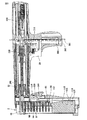
図1には、図2の長手案内部材68と、図7の軸心的固定クラッチ機構180と、図6の銃口部拘束機構130とを備えたマガジン50を有する新規な締結具打込み工具10が示される。
FIG. 1 shows a novel
図1において工具10は、前端部40、後端部24および中間領域30という3つの領域を有する。工具10は、軸心3を備えた工具本体32であって、火薬カートリッジ開口22と、ハンドル26を備え且つトリガ28により起動される図3の発射機構320を備える後端部24と、銃口部ハウジング42内に収納された銃口部44を備える前端部40とを備える工具本体32と、銃口部44に連結されて該銃口部44から側方に延在するマガジン50とを含む。
に お い て In FIG. 1, the
図2においてマガジン50上の新規な長手案内部材68は、締結具アセンブリ91を該マガジン50を通して銃口部44内へと案内する。長手案内部材68によれば、締結具アセンブリ91が工具10の後端部24に向けて逸脱(skew)してマガジン50を詰まらせることが防止される。
In FIG. 2, the new
図7においてマガジン・クラッチ・アセンブリは、マガジン50が工具本体軸心3の回りで枢動して複数の所定位置のひとつへと軸心的に固定されるのを許容する新規な軸心的固定機構180を備える。一実施例においては、4個の所定位置が在る。軸心的固定機構180によればユーザは、部屋の角隅部および他の到達困難な箇所に締結具90を固着するときにマガジン50をじゃまにならない所へ回転し得る。軸心的固定機構180は、工具10が嵩張って扱い難くなるのを防止し乍ら、マガジン50が工具本体軸心3の回りで枢動する方法を提供する。
In FIG. 7, the magazine clutch assembly is a novel axial fixation that allows the
図6において新規な銃口部拘束機構130は、マガジン50内に締結具90が無いときに工具10が発射を行うのを防止する。銃口部拘束機構130は、打込まれるべく準備された締結具90が無いときに発射機構320の作動(engagement)を防止することで、工具10に対する損傷を防止する。
In FIG. 6, the novel
工具10の配向は以下の如くである:前方は銃口部44の方向であり且つ後方は後端部24の方向である。
The orientation of the
締結具アセンブリ
図3に示された如く帯片(strip)で接合された各締結具90を備える締結具アセンブリ91はマガジン50により、ピストン210により打込まれるべく銃口部44へと案内される。図2に戻るとマガジン50は、スリーブ隆起部102と、2個のカラー92と、ヘッド・カラー98と、尖端カラー94とを有する丁合スリーブ(collation sleeve)100により相互に一列に接合された複数の締結具90を有する締結具アセンブリ91を収納すると共に該アセンブリを案内する。ヘッド・カラー98は締結具頭部106に隣接すると共に、尖端カラー94は締結具尖端部分104に隣接する。締結具90は、図3の如く各カラー92間の対応接続部97により接合されてアセンブリ91とされる。アセンブリ91の各端部における締結具90は、他の1個の締結具にのみ夫々接合される。アセンブリ91における残りの各締結具90は、その各側にて他の締結具90に夫々接合される。
Fastener Assembly A
マガジン
図2には、スライダ70およびマガジン・ハウジング60の間に囲繞された空間によりマガジン・チャンバ55が画成されることが示される。締結具アセンブリ91は、マガジン・チャンバ55内に位置する。
Magazine FIG. 2 shows that the
図1に示された如くマガジン50は、スライダ70と、マガジン・ハウジング60と、閉じ位置86においてスライダ70を所定位置に維持するラッチ80とを含む。マガジン50は締結具90をマガジン・チャンバ55内に収納して該締結具90を銃口部44へと供給する。ラッチ80が押し下げられ且つスライダ70がマガジン・ハウジング60のマガジン端部52へと移動されたとき、マガジン・チャンバ55は締結具アセンブリ91を装填する準備ができる。
The
引き続き図1に関し、マガジン・ハウジング60はマガジン50の前部区画51であると共に、締結具アセンブリ91の締結具尖端部分104を収納すべく設計される。マガジン・ハウジング60は概略的にU形状断面を有すると共に、該ハウジングは締結具アセンブリ91の尖端カラー94を支持する少なくとも一個の但し好適には二個の案内隆起部62を含む。マガジン・ハウジング60は、ラッチ80に係合するショルダ66も有する。図5に示された如くハウジング尖端凹所64は、少なくとも一個の但し好適には二個の従動部案内部材124がマガジン・ハウジング60を貫通するのを許容すべく設計される。従動部110は、締結具アセンブリ91を銃口部44に向けて適切に付勢するためにマガジン・チャンバ55内に正しく整列されねばならない。
With continued reference to FIG. 1, the
図1に示された如くスライダ70は、マガジン50の後側部53に沿って位置する区画であってマガジン・ハウジング60に沿い閉じ位置86からマガジン端部52まで摺動し得る区画である。スライダ70は、図2の如く締結具アセンブリ91の締結具頭部106を囲繞すべく設計される。
As shown in FIG. 1, the
引き続き図2に関し、スライダ70は、基部71と該基部71から側方に延在する2本のアーム72とを備えた所定材料のU形状片である。各アーム72は、マガジン・ハウジング60に沿い摺動するスライダ唇部74を以てマガジン・ハウジング60に係合する。各アーム72はまたマガジン・チャンバ55内に二つのフィンガ68も有することで、マガジン・チャンバ55の内部であるときに締結具アセンブリ91の尖端カラー94が逸脱されずに正しく整列されるのを確実にしている。
Continuing with FIG. 2, the
スライダ唇部74は、マガジン・ハウジング60のショルダ66の回りに嵌合する唇部溝76を有する。唇部溝76はマガジン・ハウジング60に係合されたスライダ70を保持すると共に、閉じ位置86からマガジン端部52へと摺動するときにスライダ70がマガジン50に沿い直線状に移動することも確実にする。
The
マガジン・チャンバ55の内部とされたときに締結具アセンブリ91が逸脱しないことを確実とすべく、一実施例において長手案内部材68は締結具90の夫々の側に位置する2本のフィンガ68として具現される。フィンガ68はスライダ70の内側表面から延在すると共に、締結具アセンブリ91上の丁合スリーブ100の尖端カラー94とヘッド・カラー98との間の空間内に位置する。フィンガ68は、尖端カラー94とヘッド・カラー98との間に配置されたスライダ70の区画から直角に延在し、次に、締結具90に平行に延伸すると共に該締結具90からほぼカラーの幅だけ離間し乍ら尖端カラー94に向けて湾曲する。尖端カラー94の前縁部95がマガジン・ハウジング60の案内隆起部62と面一に位置されたとき、フィンガ68は尖端カラー94の後縁部96に向けて延在すると共に該尖端カラーの該後縁部から0.76 mm(0.030 inch)のところで終端することから、マガジン50の内部とされたときに締結具アセンブリ91が0.76 mm(0.030 inch)を超えて後方に逸脱することが防止される。
In one embodiment, the
故に、改良された工具10は安定化部材68を備えたマガジン50を有することが理解され得る。改良された締結具打込み工具10は、軸心3を備えた工具本体32と、該工具本体32から前方に延在する銃口部ハウジング42と、該銃口部ハウジング42内に収納されて該ハウジングから前方に延在する銃口部44とを有する。
Hence, it can be seen that the
締結具90の装填時間を最短化するために工具10は締結具アセンブリ91を保持するマガジン50も有し、該マガジン50はスライダ70を有すると共に、マガジン50および該マガジン50内に配置された従動部110は該マガジン50を通して締結具90を銃口部44内に付勢すべく配置される。締結具アセンブリ91はスライダ70とマガジン・ハウジング60とにより画成されるマガジン・チャンバ55内に保持されるが、その場合にスライダ70はマガジン・ハウジング60に対して係合可能であり且つ閉じ位置86からマガジン端部52へと移動する。スライダ70は、マガジン50を通して締結具アセンブリ91を銃口部44に向けて案内する長手案内部材68であって締結具アセンブリ91がマガジン50に対して逸脱して詰まるのを防止する長手案内部材68を有する。
To minimize the loading time of the
ラッチ80はスライダ70に取付けられると共に、締結具アセンブリ91がマガジン・チャンバ55内に載置され得る様にスライダ70が固定閉じ位置86からマガジン端部52へと容易に移動するのを許容する。
The
好適実施例において、マガジン・ハウジング60はマガジン50の前部区画51であり且つスライダ70は後側部53である。ユーザは、工具10を受容基体に向けて配向し乍ら、ラッチ80を押し下げると共にスライダ70をマガジン端部52へと引き、新たな締結具アセンブリ91を装填する。
In the preferred embodiment, the
締結具の装填
図1を参照すると、スライダ70は締結具アセンブリ91の装填のためにマガジン・チャンバ55を開口したままとすべくマガジン端部52に向けて移動せねばならない。ラッチ80は、スライダ70を閉じ位置86に固定して保持する。ラッチ80はスライダ70上にて、切欠(cut out)82と交差して延伸する。
Fastener Loading Referring to FIG. 1,
図4に示された如く切欠82により、ラッチ80上のラッチ脚部88は、ショルダ・ノッチ67に嵌合することでショルダ66に係合し得る。ラッチ80は転動ピン84によりスライダ70に枢動的に取付けられると共にスプリング85により後方に付勢されることから、ラッチ脚部88はショルダ・ノッチ67に係合する。閉じ位置86においてラッチ脚部88はショルダ・ノッチ67内に嵌合すると共に、ショルダ・ノッチ67およびラッチ脚部88は当接することから、スライダ70が閉じ位置86からマガジン端部52に向けて摺動するのが抑制される。
引き続き図4を参照すると、ラッチ80が押し下げられたときに該ラッチ80はショルダ66から離間して前方に移動する。ラッチ脚部88はもはやショルダ・ノッチ67に当接しないことから、ラッチ80はマガジン端部52に向けて自由に移動する。ラッチ80は転動ピン84によりスライダ70に取付けられることから、ラッチ80が移動するときにスライダ70は共に引張られる。
Still referring to FIG. 4, when the
図2に戻ると、スライダ70はショルダ66および唇部溝76により案内されてマガジン端部52へと摺動し、締結具アセンブリ91の装填のためにマガジン・チャンバ55を開口したままとする。締結具アセンブリ91は、尖端部分104をマガジン・ハウジング60内に載置することにより、尖端カラー94の前縁部がマガジン・ハウジング60の案内隆起部62に接触するまで、マガジン・チャンバ55内に装填される。ユーザは次にスライダ70をショルダ66および相補的唇部溝76により案内され乍らマガジン50に沿い閉じ位置86へと摺動して締結具頭部106を囲繞することから、フィンガ68は締結具90の尖端カラー94の後縁部の0.76 mm(0.030 inch)上方に位置される。ユーザがスライダ70を閉じ位置86へと摺動したとき、フィンガ68は締結具アセンブリ91を案内する正しい位置を取る。ユーザは、スライダ70をマガジン端部52から閉じ位置86へと摺動させてマガジン・チャンバ55を閉成するために必要な時間以外は、各フィンガを整列させるための一切の時間を費やす必要がない。
ス ラ イ ダ Returning to FIG. 2,
従動部
図3においてマガジン50内の従動部110は、締結具アセンブリ91を銃口部44に向けて付勢する。マガジン50内の締結具アセンブリ91上で銃口部端部52の直近に位置する締結具90のスリーブ隆起部102に対しては、従動部突起112が当接する。従動部110はコイル状定圧スプリング114により銃口部44に向けて付勢されることから、締結具アセンブリ91は銃口部44に向けて引張られる。
Follower In FIG. 3,
図5には、従動部110をマガジン・チャンバ55内に正しく整列して維持するカラー隆起部122および従動部案内部材124が在る。少なくとも一個の但し好適には二個のカラー隆起部122は、マガジン・ハウジング60上の案内隆起部62とスライダ70上の安定化フィンガ隆起部68との間の空間を進むことにより、締結具アセンブリ91の尖端(tip)カラー92の経路に追随する。図2に示された如くマガジン・ハウジング60上のハウジング隆起部凹所64により生成された空間には、少なくとも一個の但し好適には二個の従動部案内部材124が嵌合する。カラー隆起部122および従動部案内部材124によれば、締結具90を銃口部44内に適切に付勢すべく従動部110が適切にマガジン・チャンバ55を通して案内されることが確実とされる。
In FIG. 5, there is a
図3においてコイル状定圧スプリング114は従動部110を銃口部44に向けて付勢する。定圧スプリング114の一端は、プレート116およびネジ118により従動部110の後縁部119に接続される。定圧スプリング114の他端は、図3に見られる如くスライダ70におけるブッシュ120の回りに巻き付けられる。ブッシュ120は、ラッチ転動ピン84の回りに嵌合する。締結具アセンブリ91がマガジン・チャンバ55内に装填されると共にスライダ70が閉じ位置86へと摺動した後、締結具アセンブリ91はマガジン・チャンバ55内に在ることから従動部110はマガジン端部52に残存する。定圧スプリング114は従動部110に力を及ぼすことで、該従動部110および締結具アセンブリ91を銃口部44に向けて付勢する。締結具90が銃口部44から打出されて締結具アセンブリ91が短くなるにつれ、定圧スプリング114は増加的にブッシュ120の回りに巻き付いて従動部110を銃口部44に向けて引張ることから、締結具アセンブリ91を銃口部44に向けて付勢する。
(3) In FIG. 3, the coiled
工具10のマガジン50は、ラッチ80および定圧スプリング114を含む。ラッチ80に依れば、スライダ70が取付けられたラッチ80をマガジン・ハウジング60に沿いマガジン端部52へと摺動することでユーザがスライダ70をマガジン端部52へと容易に移動し得ることに加え、スライダ70は閉じ位置86へと容易に固定され得る。
The
従動部110はスライダに接続されると共に、ラッチ80が押し下げられてマガジン端部52へと引張られるときにマガジン・チャンバ55内でマガジン端部52へと移動する。締結具アセンブリ91がマガジン・チャンバ55内に導入されたとき、従動部110はマガジン・チャンバ55内のマガジン端部52に適切に位置されたままとされて締結具アセンブリ91を銃口部44に向けて付勢する一方、スライダ70は閉じ位置86へと摺動する。
The
コイル状定圧スプリング114は締結具アセンブリ91に対して均一圧力を付与することから、締結具90は均等な力で銃口部44内へと供給されると共に締結具90は常に銃口部44内に適切に位置される。マガジン・チャンバ55内における締結具アセンブリ91の存在の故に、スライダ70がマガジン・ハウジング60に沿いマガジン端部52から閉じ位置86へと移動される時にコイル状定圧スプリング114は巻き出される。コイル状定圧スプリング114は、スライダ70が閉じ位置86へと摺動されたときに自動的に適切に締結具アセンブリ91を付勢すべく配置される。コイル状定圧スプリングは締結具の装填の間に個別に固定および配置される必要が無いので、締結具の装填の間における時間が節約される。
Since the coiled
拘束機構(Lock-out Mechanism)
図6を参照すると、全ての締結具90が銃口部44から打出されたとき、工具10は締結具無し状態135に在る。拘束機構130は、銃口部44が発射準備位置2へと移動するのを防止することで、締結具無し状態135の間に工具10が発射を行わないのを確実にする。図7に見られる如く工具10はマガジン50もしくは緩衝器アセンブリ190内に締結具90が無いときに発射を行ってはならず、且つ、図3に見られる如く従動部110はピストン210の自由フライトにより損傷される可能性がある。
Lock-out Mechanism
Referring to FIG. 6, when all
図6に示された如く、全ての締結具90は銃口部44から打出されており、工具10は締結具無し状態135に在る。銃口部44内に締結具接触部分113が位置し乍ら、従動部110は銃口部壁部45内の開口48に嵌合する。拘束機構130は、銃口部壁部表面47により形成された停止部46であって銃口部壁部開口48によりアクセス可能とされて従動部110のブロック用表面(blocking surface)126に当接する停止部46を含む。
As shown in FIG. 6, all
従動部110の前面125は、ブロック用表面126を提供する。締結具無し状態135の間において銃口部44が受容基体に対して押圧されたとき、銃口部壁部45の露出表面47は従動部110の前面125と接触する状態となる。従動部110は軸心的に変位しないことから、従動部110の前面125との接触により、銃口部44が、図3の如く該銃口部44が銃口部ハウジング42と面一となる時に発射準備位置2を取ることが防止される。
前面 The
改良された銃口部44および従動部110によれば、工具10上の直接的銃口部拘束機構130は締結具無し状態135の間において工具10が発射を行うのを防止し得る。直接的銃口部拘束機構130によれば、図3のように、締結具無し状態135の間に銃口部44は発射準備位置2とはならず、ピストン210は発射を行わず、且つ、工具10はピストン210により損傷されないことが確実とされる。
With the improved
図1に戻ると締結具打込み工具10は、工具本体32と、該工具本体32から前方に延在する銃口部ハウジング42と、該銃口部ハウジング42から前方に延在すると共に図3の如く発射準備位置2へと変位可能な銃口部44とを有する。工具10は、銃口部44と連結されたマガジン50であって銃口部44から側方に延在するマガジン50を含む。マガジン50内には従動部110が配置され、マガジン50を通して締結具90を銃口部44内へと付勢する。従動部110は締結具接触部分113およびブロック用表面126を有する。図3に見られる如く全ての締結具90がマガジン50を介して銃口部44内へと供給され、ピストン210により銃口部44から打出された場合、マガジン50が締結具無し状態135に在るときにブロック用表面126は銃口部44をブロックし、銃口部44が発射準備位置2へと変位されるのを防止する。銃口部44が発射準備位置2を取ることが阻止されたときに工具10は発射を行わないので、工具10はピストン210の自由フライトによる損傷から保護される。
Returning to FIG. 1, the
マガジン・クラッチ
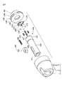
図7においてマガジン・クラッチは、銃口部アセンブリ140の一部である銃口部44に関連する軸心的固定機構(axial locking mechanism)180により形成される。軸心的マガジン・クラッチ180は軸心的固定力により銃口部アセンブリ140を銃身35に対して所定位置に軸心的に固定する手段を提供することから、操作者が銃口部アセンブリ140に関して適切な係合解除トルクを提供しなければ銃口部アセンブリ140および連結されたマガジン50は工具本体軸心3の回りで回転し得ない。
Magazine Clutch In FIG. 7, the magazine clutch is formed by an
軸心的固定機構180は、雌部材に嵌合する雄部材により達成される。好適実施例において、雄部材は銃口部アセンブリ140の後部から突出するスプリング付勢式ボール軸受160である。好適な雌部材は、緩衝器アセンブリ190の保持プレート192上のソケット194である。
軸心的固定機構180によれば締結具打込み工具10上のマガジン50は、該工具を嵩高くせず(non-bulky)に工具本体軸心3の回りで回転し得る。選択された4つの所定位置のひとつへとマガジン50を回転すると、ユーザは部屋の角隅部および他の到達困難な箇所へと締結具を適切に打込むべく工具を位置決めできる。軸心的固定機構180によれば、工具本体32の周囲寸法が大きくなりすぎたり高重量で扱いにくくなるのを防ぎ乍ら、マガジン50は工具本体軸心3の回りで回転し得る。
According to the
軸心的固定機構180を有する締結具打込み工具10は、軸心3を備えた工具本体32と、内部においてピストン210を収納かつ案内する同軸的に収納された銃身35を有する。緩衝器アセンブリ190は、保持プレート192を有すると共に、銃身35内に収納されることでピストン210のフライトを制御する。銃口部ハウジング42が工具本体32から前方に延在すると共に、固定子150が銃身35に対して同軸的に接続されて該銃身35から前方に延在する。銃口部アセンブリ140は固定子150に対して回転可能に接続されると共に、銃口部ハウジング42を貫通して該ハウジングから前方に延在する。マガジン50は締結具アセンブリ91を保持すると共に、一端にて銃口部アセンブリ140に連結され且つ該銃口部アセンブリ140から側方に延在する。マガジン50および銃口部アセンブリ140は工具本体軸心3の回りにて、所定個数の解除可能固定位置へと回転可能である。軸心的固定機構180は、緩衝器アセンブリ190により銃口部アセンブリ140と係合することで、銃口部アセンブリ140および連結されたマガジン50を所定の解除可能固定位置のひとつへと解除可能に固定する。
The
銃口部アセンブリ(Muzzle Assembly)
図7において軸心的固定機構180は銃口部アセンブリ140と連携されると共に、銃口部アセンブリ140と、銃身35内の緩衝器アセンブリ190の保持ケージ195上の保持プレート192との間に軸心的固定力を提供すべく作用する。
Muzzle Assembly
In FIG. 7, an
軸心的固定機構180は銃口部アセンブリ140と連携されるが、該アセンブリは、前端部41および後端部43を有する銃口部44であってマガジン50に接続されると共に銃口部ハウジング42を貫通延在して該ハウジングから前方に延在する銃口部44を含む。背板170は、前面173と、後面178と、孔172とを有すると共に、銃口部44の後側部43に対して据込まれる(スウェイジ(swedge)される)。銃口部44の後側部43にては、軸心方向に延伸するチャネル200が在る。銃口部44内のチャネル200内にはスプリング176が収納され、前面161および後面162を各々有するボール軸受160はスプリング176により背板170の方向に付勢される。チャネル200内のスプリング176はボール軸受160を背板170における孔172に対して付勢すると共に、ボール軸受160は背板170により保持され、ボール軸受160の後面162は背板170の後面178の外方を向く。緩衝器アセンブリ190の保持プレート192は、ボール軸受160の後面162を受容するソケット194を有する。
The
ユーザは、工具10とは別個に銃口部アセンブリ140を組立ててから該銃口部アセンブリ140を工具10内に挿入し得る。銃口部アセンブリ140の各片は工具本体32内に挿入されて該工具本体32内で適切に位置される必要は無い。工具の組立ておよび修理の作業は、銃口部アセンブリ140により相当に容易とされる。
The user can assemble the
図8に示された如く銃口部アセンブリ140は、銃口部ハウジング42を貫通延在して該ハウジングから前方に延在すると共に、キー184およびネジ182により所定位置に保持される。銃口部44は前端部41および後端部43を含むと共に、環状ショルダ141は概略的に後端部に配置され且つ主要部分143は環状ショルダ141から離間して前方に向けて軸心方向に延在する。ショルダ141の外径は主要部分143の外径より僅かに大寸であることから、ショルダ141は主要部分143から外径方向に延在する。
8, the
図7に示された如く銃口部44の後端部43は、相互から90°間隔で等距離に離間された4本の軸心チャネル200を有し、これらはスプリング176を収納する。2つのチャネル200の中央に直接的に位置する軸心方向ピン・チャネル204が在る。
As shown in FIG. 7, the rear end 43 of the
背板170は、前面173および後面178を有すると共に、銃口部ショルダ141の後部に位置する。背板170は直径が3.96 mm(0.156 inch)より僅かに小寸の5個の孔を有するが、4個の孔172は相互から90°間隔で等距離に離間されると共に、第5孔すなわちピン孔174は背板170上の2つの孔の中央に直接的に位置する。等距離に離間された4個の孔172は、以下に記述される如くボール軸受160を保持すべく設計される。
The
引き続き図7に関し、背板170は外側据込部152および内側据込部154により銃口部44に据込まれ、銃口部44に固定される。外側据込部152は銃口部44の後側部43の外側縁部151に沿い延伸すると共に、内側据込部154は内側縁部153に沿い延伸する。背板170の前面173は銃口部44の後側部43に対して保持されると共に、ピン孔174がピン・チャネル204と整列する如く配向される。ピン175はピン孔174を貫通して延伸すると共に銃口部44内のピン・チャネル204に嵌合することから、銃口部44の後部に対して背板170が適切に整列維持されることが確実となる。
Continuing with FIG. 7, the
以下に記述される如く各チャネル200内には夫々のチャネル内に1本として4本のスプリング176が載置されることで、各ボール軸受160を、背板170上の孔172に対し且つ保持プレート192上の4個のソケット194内へと付勢する。好適実施例において上記スプリングは、3.76 mm(0.148 inch)の外径(OD)であり且つ7.94 mm(5/16 inch)長である。
As described below, four
スプリング176により4個のボール軸受160が背板170に対して付勢されると共に、4個の孔172により保持される。好適実施例において該ボール軸受は、マックマスターカール(McMaster Carr)社からの部品番号#9528K12を有する3.96 mm(0.156 inch(5/32))クロム鋼軸受である。ボール軸受160の後面162は背板170の後面178の外方を向くことから、軸心的固定機構180の雄部材を構成する。
(4) The four
緩衝器アセンブリ
図7において緩衝器アセンブリ190は、軸心的固定機構180の雌部材を構成するソケット194を含む。図3に示された如く緩衝器アセンブリ190は、締結具打込みの間においてピストン210のフライトを停止する二部材システムである。緩衝器アセンブリ190は、保持ケージ195および緩衝器本体196を備える。保持ケージ195は、前面191と後面193とを有する環状保持プレート192を有する。保持プレート192の前面191は、相互に90°間隔で等距離に離間された4個のソケット194を有する。保持プレート192の後面193は、緩衝器本体196に当接する。
Shock Absorber Assembly In FIG. 7, the
銃口部アセンブリ140上の4個のボール軸受160の後面162は、4個の所定位置のひとつに在るときに保持プレート192の前面191上で等距離に離間された4個のソケット194に嵌合する。4個のソケット194は、半球的に陥没されると共に、直径は3.96 mm(0.156 inch)より僅かに小さい。
The
マガジンクラッチ機構
銃口部アセンブリ140上の4個のボール軸受160の各々と保持プレート192の前面191上の4個のソケット194の各々との間における係合により、工具本体軸心3の回りにおける4個の所定個数の位置のひとつに銃口部アセンブリ140および連結されたマガジン50を保持する軸心的固定機構180が提供される。スプリング176は3乃至6 inch-pounds (0.339-0.678 N・m)の係合解除トルクを必要とする力をボール軸受160に及ぼすが、これは工具10の動作の間に銃口部アセンブリ140および連結されたマガジン50を所定位置に維持するに十分なトルクであって、操作者がその意志により銃口部アセンブリ140および連結されたマガジン50を移動するのを妨げるほど大きなトルクではない。
Magazine clutch mechanism Engagement between each of the four
好適には銃口部アセンブリ140は、改善された製造、修理および動作のために、該銃口部アセンブリを工具10に取付ける前に半組立部品として組立てられる。
Preferably, the
銃口部および固定子の組立て
図7において銃口部アセンブリ140は固定子150内に回転可能に収納されることから、連結されたマガジン50と共に銃口部アセンブリ140は静止側の工具本体32と静止側の共軸的な銃身35内で工具本体32の軸心の回りで回転し得る。
Assembling of Muzzle and Stator In FIG. 7, the
銃口部44は固定子150に対して回転可能に接続されると共に、該固定子150は銃身35に対して接続される。固定子150は概略的に環状の形状である一方、銃口部アセンブリ140は固定子150の環形の内径より僅かに小寸の外径を有する概略的な円筒形状なので、銃口部アセンブリ140は固定子150内に嵌合する。
The
図8に示された如く固定子150は、概略的には当該前側部157に配置された環状フランジ159を備えた前側部157および後側部158、ならびに、フランジ159から軸心方向に後方に延在する円筒部155を含む。固定子150はボア156を有する。銃口部ショルダ141は、径方向にて固定子150のボア156内に嵌合する。銃口部44の主要部分143は所定許容差内で固定子150内に嵌合することから、銃口部44は回転し得る。
As shown in FIG. 8, the
銃口部44の前端部は、固定子150の後側部からボア156内に挿入される。銃口部44はショルダ141の前面が固定子150上に円筒部155の後面で係合するまで固定子150を貫通して前方に引張られることから、銃口部44は固定子150に対してそれ以上は打込み方向に移動され得ない。固定子150は銃口部44と連結されたマガジン50が工具本体軸心3の回りで回転するのを許容し乍ら銃口部44を軸心的に所定位置に保持することから、ユーザは到達困難な箇所に締結具90を打込むべく工具10を更に良好に位置決めできる。
前 The front end of the
マガジン圧縮の安全機能
工具10が発射を行うために銃口部44は、該銃口部44を受容基体に対して押圧することで図3の如く該銃口部44が銃口部ハウジング42と面一となる発射準備位置2まで変位されねばならない。図1に見られる如く安全機構5は、ユーザが工具10を、単純にマガジン50上で引き戻すことで発射準備位置2に置くことを防止する。工具10を発射準備位置2に置くには、基体に対して銃口部44が押圧されねばならない。
Safety function of magazine compression The
キー184は、ネジ182により銃口部用キー孔188内に螺着される。銃口部ハウジング42におけるチャネル200内にはスプリング186が収納される。スプリング186は、工具10の前端部40に向けてキー184を付勢する。銃口部44は、該銃口部44が受容基体に対して押圧されなければ変位し得ない。単にマガジン50上で引き戻すだけでは銃口部44は発射準備位置2に設定されない、と言うのも、スプリング186は銃口部44に取付けられたキー184を付勢するので発射準備位置2への変位が防止されるからである。
The key 184 is screwed into the muzzle part key hole 188 by a
カートリッジ式発射機構
図3に見られる如く締結具打込み工具10は、発射機構320により爆発性発射火薬カートリッジ300を点火することで発射を行う。工具10に対して複数の爆発性火薬カートリッジ300が供給されるのを許容すべく、各カートリッジ300はカートリッジ・チャネル305に沿い発射機構320に供給されるカートリッジ帯片301上に配置される。工具10が発射を行った後で使用済カートリッジ300が発射機構320から離間移動されて新たなカートリッジ300が発射機構320に供給され得る如く、工具10はカートリッジ帯片301の割出し(indexing)のための(不図示の)前進機構を含むのが望ましい。該前進機構は、工具10が発射を行った後で自動的にカートリッジ帯片301を割出すのが更に望ましい。
3. Cartridge Type Firing Mechanism As seen in FIG. 3,
カートリッジ式発射機構の例は、代理人処理番号#13819を有すると共に“締結具打込み工具用のカートリッジ帯片前進機構(Cartridge Strip Advancing Mechanism For Fastener Driving Tool)”と称されて本発明と同様に本出願人に譲渡された特許出願に開示されるが、これは言及したことにより本明細書中に援用される。 An example of a cartridge-type firing mechanism has an agent processing number # 13819 and is called a “Cartridge Strip Advancing Mechanism For Fastener Driving Tool” as well as the present invention. Disclosed in the commonly assigned patent application, which is hereby incorporated by reference.
工具の動作
工具10は、上記で詳述された如く先ず締結具アセンブリ91をマガジン・チャンバ55内に装填してからスライダ70を閉じ位置86へと摺動してマガジン・チャンバ55を閉じることで、使用状態とされる。銃口部44は、該銃口部44が発射準備位置2を取るように基体に対して押圧されねばならない。次にユーザは、トリガ28を引いて発射機構を起動せねばならない。ピンを起動するとカートリッジ300が衝撃を加えられて該カートリッジ300が点火され、結果的な燃焼によりピストン210が駆動される。ピストン210は銃身35内で前方に変位して締結具アセンブリ91上の締結具90の頭部106に衝当し、締結具90を銃口部44から基体内へと打込む。
Tool Operation The
到達困難な箇所へと締結具を打込む場合、ユーザはマガジン端部52に力を付与すると共にクラッチ機構180を利用してマガジン50を回転し得る。全ての締結具90がマガジン50を通して付勢されると共に基体へと打込まれたときにユーザは工具10の発射を行えない、と言うのも、ユーザが工具10を基体に押圧したときに銃口部44は銃口部拘束機構130の故に発射準備位置2へと変位されないからである。
When driving fasteners into hard-to-reach locations, the user can apply force to the
要約すると、締結具打込み工具10はマガジン50上の新規な長手案内部材68であってマガジン50を介して銃口部44内へと締結具アセンブリ91を案内することで締結具アセンブリ91が工具10の後端部24に向けて逸脱してマガジン50を詰まらせるのを防止する長手案内部材68を有することが理解され得る。上記工具の別の新規な特徴は軸心的クラッチ機構180であるが、該機構は、マガジン50が工具本体軸心3の回りで枢動すると共に4個の所定位置のひとつに軸心的に固定されることで、締結具を角隅部および他の到達困難な箇所に固着するときにユーザが工具10を適切に位置決めするのを可能とする。上記工具の別の新規性は銃口部拘束機構130であり、該機構は、打込まれる準備ができた締結具90が無いときに銃口部44が発射準備位置2へと移動するのを従動部110により阻止することで、マガジン50内に締結具90が無いときに工具10が発射を行うのを防止する。
In summary, the
3…軸心
32…工具本体
44…銃口部
50…マガジン
90…締結具
110…従動部
126…ブロック用表面
3 ...
Claims (10)
上記工具本体内で上記軸心に沿い案内されて締結具を打込むピストンと、
上記工具本体から軸心方向において前方に延在すると共に発射準備位置へと変位可能な銃口部と、
上記締結具を保持すると共に上記銃口部に連結された端部を有するマガジンと、
上記マガジンを通して上記銃口部内へと上記締結具を付勢すべく構成され上記マガジン内に配置された従動部と、を備え、
上記従動部は、上記マガジンが締結具無し状態に在るときに上記銃口部をブロックするブロック用表面であって上記銃口部が上記発射準備位置へと変位されるのを防止するブロック用表面を有する、
締結具打込み工具。 A tool body having an axis,
A piston guided along the axis in the tool body and driving a fastener;
A muzzle portion extending forward from the tool body in the axial direction and displaceable to a firing preparation position,
A magazine holding the fastener and having an end connected to the muzzle;
A driven portion arranged to bias the fastener into the muzzle portion through the magazine and disposed in the magazine;
The driven portion is a blocking surface that blocks the muzzle portion when the magazine is in the fastener-less state, and that is a blocking surface that prevents the muzzle portion from being displaced to the firing preparation position. Have,
Fastener driving tool.
上記壁部は、締結具無し状態の間に上記従動部の前記ブロック用表面に接触する停止部であって上記銃口部が発射準備位置を取るのを防止する停止部を有する、請求項1記載の締結具打込み工具。 The muzzle has a wall with an opening that allows the driven part to penetrate the muzzle wall during the absence of the fastener,
The wall of claim 1, wherein the wall has a stop that contacts the blocking surface of the follower during the absence of fasteners and prevents the muzzle from taking a fire ready position. Fastener driving tool.
前記ブロック用表面は上記前面の一部を形成し、且つ、
上記開口は、締結具無し状態の間において上記ブロック用表面に接触する表面であって上記銃口部が発射準備位置を取るのを防止する表面を有する、請求項1記載の締結具打込み工具。 The muzzle has a wall with an opening that allows the front surface of the driven part to pass through the muzzle wall during the absence of the fastener,
The block surface forms part of the front surface, and
The fastener driving tool according to claim 1, wherein the opening has a surface that contacts the blocking surface during a fastener-less state and prevents the muzzle from taking a fire ready position.
上記銃口部は上記銃口部ハウジングから軸心方向において前方に延在する、請求項1記載の締結具打込み工具。 The fastener driving tool further comprises a housing for the muzzle,
The fastener driving tool according to claim 1, wherein the muzzle portion extends axially forward from the muzzle housing.
上記銃身は前記ピストンを収納かつ案内する、請求項1記載の締結具打込み工具。 The fastener driving tool further comprises a barrel coaxially housed within the tool body,
The fastener driving tool according to claim 1, wherein the barrel houses and guides the piston.
Applications Claiming Priority (1)
| Application Number | Priority Date | Filing Date | Title |
|---|---|---|---|
| US10/245,942 US7021511B2 (en) | 2002-09-18 | 2002-09-18 | Lock-out mechanism for powder actuated tool |
Publications (2)
| Publication Number | Publication Date |
|---|---|
| JP2004106181A true JP2004106181A (en) | 2004-04-08 |
| JP2004106181A5 JP2004106181A5 (en) | 2006-09-14 |
Family
ID=31946411
Family Applications (1)
| Application Number | Title | Priority Date | Filing Date |
|---|---|---|---|
| JP2003326051A Pending JP2004106181A (en) | 2002-09-18 | 2003-09-18 | Fastener driving tool |
Country Status (6)
| Country | Link |
|---|---|
| US (1) | US7021511B2 (en) |
| EP (1) | EP1400314A1 (en) |
| JP (1) | JP2004106181A (en) |
| KR (1) | KR101053476B1 (en) |
| AU (1) | AU2003244628B2 (en) |
| CA (1) | CA2441145C (en) |
Cited By (3)
| Publication number | Priority date | Publication date | Assignee | Title |
|---|---|---|---|---|
| JP2006043859A (en) * | 2004-08-09 | 2006-02-16 | Jpf Works Kk | Hammering tool |
| WO2011039905A1 (en) * | 2009-10-03 | 2011-04-07 | アサヒビール株式会社 | Method for sending a falling body in a falling-body viscometer, falling-body sending device, and falling-body viscometer provided therewith |
| JP4897789B2 (en) * | 2005-03-28 | 2012-03-14 | イリノイ トゥール ワークス インコーポレイティド | Power nailing machine with block mechanism of driving blade |
Families Citing this family (23)
| Publication number | Priority date | Publication date | Assignee | Title |
|---|---|---|---|---|
| US7971768B2 (en) * | 2004-05-04 | 2011-07-05 | Illinois Tool Works Inc. | Guidance system for fasteners |
| DE102006000254A1 (en) * | 2006-05-30 | 2007-12-06 | Hilti Ag | Hand-operated setting tool |
| US20080067212A1 (en) * | 2006-09-14 | 2008-03-20 | Wan-Fu Wen | Magazine for Nail Gun |
| DE102006035410B4 (en) * | 2006-11-08 | 2015-06-03 | Hilti Aktiengesellschaft | Positioning device with tripping mediation for a hand-held setting tool |
| CA2672308C (en) * | 2006-12-29 | 2012-08-07 | Illinois Tool Works Inc. | Cordless fastener tool with fastener driving and rotating functions |
| DE102007000025A1 (en) * | 2007-01-19 | 2008-08-28 | Hilti Ag | Hand-operated setting tool |
| US8152038B2 (en) * | 2007-03-16 | 2012-04-10 | Illinois Tool Works Inc. | Nose assembly for a fastener driving tool |
| DE102009027317B4 (en) * | 2009-06-30 | 2019-12-05 | Robert Bosch Gmbh | Tool |
| US8746526B2 (en) * | 2009-09-15 | 2014-06-10 | Robert Bosch Gmbh | Fastener driver with blank fire lockout |
| US8336748B2 (en) * | 2009-09-15 | 2012-12-25 | Robert Bosch Gmbh | Fastener driver with driver assembly blocking member |
| US8292143B2 (en) | 2010-10-12 | 2012-10-23 | Stanley Fastening Systems, L.P. | Dry fire lockout with bypass for fastener driving device |
| US8678261B2 (en) * | 2011-07-08 | 2014-03-25 | Chung-Yi Lee | Position-limiting device and magazine |
| USD775505S1 (en) * | 2013-12-11 | 2017-01-03 | Hilti Aktiengesellschaft | Powder actuated tool |
| US9946590B2 (en) | 2013-12-19 | 2018-04-17 | Hewlett Packard Enterprise Development Lp | Transmission of command strings and status strings via memory bus |
| EP3253534B1 (en) | 2015-02-06 | 2020-05-06 | Milwaukee Electric Tool Corporation | Gas spring-powered fastener driver |
| USD790940S1 (en) | 2015-12-17 | 2017-07-04 | Illinois Tool Works Inc. | Powder actuated tool |
| US10828762B2 (en) * | 2017-09-22 | 2020-11-10 | Illinois Tool Works Inc. | Powered fastener driving tool |
| US11123851B2 (en) | 2017-10-27 | 2021-09-21 | Illinois Tool Works Inc. | Tool with charge advance mechanism |
| AU2018250391A1 (en) | 2017-10-27 | 2019-05-16 | Illinois Tool Works Inc. | Tool with charge advance mechanism |
| US11110577B2 (en) | 2017-11-16 | 2021-09-07 | Milwaukee Electric Tool Corporation | Pneumatic fastener driver |
| USD865471S1 (en) * | 2018-03-01 | 2019-11-05 | Hilti Aktiengesellschaft | Powder actuated tool |
| US11376721B2 (en) | 2020-05-22 | 2022-07-05 | Milwaukee Electric Tool Corporation | Dry-fire lockout and last fastener retention mechanism for powered fastener driver |
| WO2022159538A1 (en) | 2021-01-20 | 2022-07-28 | Milwaukee Electric Tool Corporation | Powered fastener driver |
Citations (2)
| Publication number | Priority date | Publication date | Assignee | Title |
|---|---|---|---|---|
| JPS573726Y2 (en) * | 1976-01-13 | 1982-01-23 | ||
| US4809898A (en) * | 1986-03-12 | 1989-03-07 | Hilti Aktiengesellschaft | Explosive charge operated tool for fastening elements |
Family Cites Families (21)
| Publication number | Priority date | Publication date | Assignee | Title |
|---|---|---|---|---|
| US3606128A (en) * | 1967-03-07 | 1971-09-20 | Reich Maschf Gmbh Karl | Percussion machine for fasteners |
| US4197974A (en) * | 1978-06-12 | 1980-04-15 | Speedfast Corporation | Nailer |
| US4463888A (en) * | 1981-04-22 | 1984-08-07 | Duo-Fast Corporation | Fastener driving tool |
| US4597517A (en) * | 1985-06-21 | 1986-07-01 | Signode Corporation | Magazine interlock for a fastener driving device |
| DE3806625A1 (en) | 1988-03-02 | 1989-09-14 | Hilti Ag | POWDER POWERED SETTING DEVICE |
| DE4022674A1 (en) * | 1990-07-17 | 1992-01-23 | Hilti Ag | POWDER POWERED SETTING DEVICE |
| JP2640988B2 (en) * | 1990-11-30 | 1997-08-13 | 株式会社 マキタ | Prevention device for empty hitting of nails in nailing machine |
| DE4122873A1 (en) | 1991-07-11 | 1993-01-14 | Hilti Ag | POWDER-POWERED SETTING UNIT WITH MAGAZINE FOR FASTENING ELEMENTS |
| AU667162B2 (en) | 1993-05-13 | 1996-03-07 | Stanley-Bostitch, Inc. | Fastener driving device particularly suited for use as a roofing nailer |
| DE4406556C1 (en) | 1994-03-01 | 1995-08-03 | Herberg Gmbh & Co Kg | Magazine equipped with bolts for a powder-operated setting tool |
| JP3419535B2 (en) * | 1994-03-11 | 2003-06-23 | 株式会社マキタ | Nailing machine |
| DE19642295A1 (en) | 1996-10-14 | 1998-04-16 | Hilti Ag | Powder-powered setting tool with magazine for fasteners |
| FR2766403B1 (en) | 1997-07-25 | 1999-09-17 | Spit Soc Prospect Inv Techn | SEAL OF BUFFER SEALING RINGS FOR BUFFER SEALING APPARATUS |
| JP3558884B2 (en) * | 1998-08-10 | 2004-08-25 | 株式会社マキタ | Nailing machine |
| EP0987086A3 (en) | 1998-09-18 | 2000-12-20 | Ramset Fasteners (Aust.) Pty. Ltd. | Power actuated tools with magazine feed |
| US6036072A (en) | 1998-10-27 | 2000-03-14 | De Poan Pneumatic Corporation | Nailer magazine |
| WO2000059687A1 (en) * | 1999-04-05 | 2000-10-12 | Stanley Fastening Systems, L.P. | Safety trip assembly and trip lock mechanism for a fastener driving tool |
| US6056181A (en) * | 1999-08-24 | 2000-05-02 | Besco Pneumatic Corp. | Fastening machine |
| US6149046A (en) * | 1999-11-01 | 2000-11-21 | Basso Industry Corp. | Safety device for preventing ejecting mechanism from hitting pushing member in a magazine of a power stapler |
| US6592014B2 (en) * | 2001-12-13 | 2003-07-15 | Illinois Tool Works Inc. | Lockout mechanism for fastener driving tool |
| US20030121948A1 (en) | 2001-12-31 | 2003-07-03 | Hsien Chen Ming | Device for disabling shooting when nails runs out in a pneumatic nailer |
-
2002
- 2002-09-18 US US10/245,942 patent/US7021511B2/en not_active Expired - Fee Related
-
2003
- 2003-09-10 AU AU2003244628A patent/AU2003244628B2/en not_active Ceased
- 2003-09-16 KR KR1020030063968A patent/KR101053476B1/en not_active IP Right Cessation
- 2003-09-16 CA CA002441145A patent/CA2441145C/en not_active Expired - Fee Related
- 2003-09-18 EP EP03292305A patent/EP1400314A1/en not_active Withdrawn
- 2003-09-18 JP JP2003326051A patent/JP2004106181A/en active Pending
Patent Citations (2)
| Publication number | Priority date | Publication date | Assignee | Title |
|---|---|---|---|---|
| JPS573726Y2 (en) * | 1976-01-13 | 1982-01-23 | ||
| US4809898A (en) * | 1986-03-12 | 1989-03-07 | Hilti Aktiengesellschaft | Explosive charge operated tool for fastening elements |
Cited By (6)
| Publication number | Priority date | Publication date | Assignee | Title |
|---|---|---|---|---|
| JP2006043859A (en) * | 2004-08-09 | 2006-02-16 | Jpf Works Kk | Hammering tool |
| JP4593999B2 (en) * | 2004-08-09 | 2010-12-08 | 日本パワーファスニング株式会社 | Driving tool |
| JP4897789B2 (en) * | 2005-03-28 | 2012-03-14 | イリノイ トゥール ワークス インコーポレイティド | Power nailing machine with block mechanism of driving blade |
| WO2011039905A1 (en) * | 2009-10-03 | 2011-04-07 | アサヒビール株式会社 | Method for sending a falling body in a falling-body viscometer, falling-body sending device, and falling-body viscometer provided therewith |
| US8573029B2 (en) | 2009-10-03 | 2013-11-05 | Asahi Group Holdings, Ltd. | Method for sending a falling body in a falling-body viscometer, falling-body sending device, and falling-body viscometer provided therewith |
| JP5436567B2 (en) * | 2009-10-03 | 2014-03-05 | アサヒグループホールディングス株式会社 | Falling body delivery method, falling body delivery apparatus, and falling body viscometer including the same |
Also Published As
| Publication number | Publication date |
|---|---|
| EP1400314A1 (en) | 2004-03-24 |
| KR101053476B1 (en) | 2011-08-03 |
| AU2003244628B2 (en) | 2006-05-11 |
| US20040050897A1 (en) | 2004-03-18 |
| CA2441145A1 (en) | 2004-03-18 |
| KR20040025585A (en) | 2004-03-24 |
| CA2441145C (en) | 2008-07-08 |
| US7021511B2 (en) | 2006-04-04 |
| AU2003244628A1 (en) | 2004-04-08 |
Similar Documents
| Publication | Publication Date | Title |
|---|---|---|
| JP2004106181A (en) | Fastener driving tool | |
| US6761299B2 (en) | Magazine clutch assembly | |
| US5425488A (en) | Impact actuated tool for driving fasteners | |
| US6267284B1 (en) | Power actuated tools with magazine feed | |
| US7059507B2 (en) | Apparatus for driving fasteners, with safety shoe | |
| US4821938A (en) | Powder-actuated fastener driving tool | |
| JPS62218078A (en) | Riveter | |
| US20150316339A1 (en) | Firearm magazine adapter and release assembly | |
| US8777079B2 (en) | Nail gun capable of preventing its trigger from being pulled in nail-empty condition | |
| TWI230111B (en) | Cartridge strip advancing mechanism for fastener driving tool | |
| US4074843A (en) | Fastening element feeding device for an explosive powder driven setting gun | |
| US6834788B2 (en) | Magazine assembly with stabilizing members | |
| NZ196646A (en) | Piston return mechanism for fastener driver:piston returned by contact with tilting muzzle bushing | |
| US2740965A (en) | Stud driving tool | |
| US8016174B2 (en) | Indirect fire device for fixing fasteners in a substrate material | |
| US20230264331A1 (en) | Magazine fastener guide for a fastener driving tool | |
| AU754213B2 (en) | Power actuated tools with magazine feed | |
| US20030019902A1 (en) | Cartridge strip advancing mechanism for fastener driving tool |
Legal Events
| Date | Code | Title | Description |
|---|---|---|---|
| A521 | Request for written amendment filed |
Free format text: JAPANESE INTERMEDIATE CODE: A523 Effective date: 20060726 |
|
| A621 | Written request for application examination |
Free format text: JAPANESE INTERMEDIATE CODE: A621 Effective date: 20060726 |
|
| A131 | Notification of reasons for refusal |
Free format text: JAPANESE INTERMEDIATE CODE: A131 Effective date: 20090714 |
|
| A601 | Written request for extension of time |
Free format text: JAPANESE INTERMEDIATE CODE: A601 Effective date: 20091013 |
|
| A602 | Written permission of extension of time |
Free format text: JAPANESE INTERMEDIATE CODE: A602 Effective date: 20091016 |
|
| A521 | Request for written amendment filed |
Free format text: JAPANESE INTERMEDIATE CODE: A523 Effective date: 20091120 |
|
| A131 | Notification of reasons for refusal |
Free format text: JAPANESE INTERMEDIATE CODE: A131 Effective date: 20100615 |
|
| A601 | Written request for extension of time |
Free format text: JAPANESE INTERMEDIATE CODE: A601 Effective date: 20100914 |
|
| A602 | Written permission of extension of time |
Free format text: JAPANESE INTERMEDIATE CODE: A602 Effective date: 20100917 |
|
| A02 | Decision of refusal |
Free format text: JAPANESE INTERMEDIATE CODE: A02 Effective date: 20101214 |