JP2004101175A - Fluid injection device and fluid injection method - Google Patents
Fluid injection device and fluid injection method Download PDFInfo
- Publication number
- JP2004101175A JP2004101175A JP2003321695A JP2003321695A JP2004101175A JP 2004101175 A JP2004101175 A JP 2004101175A JP 2003321695 A JP2003321695 A JP 2003321695A JP 2003321695 A JP2003321695 A JP 2003321695A JP 2004101175 A JP2004101175 A JP 2004101175A
- Authority
- JP
- Japan
- Prior art keywords
- fuel
- combustion
- injection device
- injector
- jets
- Prior art date
- Legal status (The legal status is an assumption and is not a legal conclusion. Google has not performed a legal analysis and makes no representation as to the accuracy of the status listed.)
- Pending
Links
Images


Classifications
-
- F—MECHANICAL ENGINEERING; LIGHTING; HEATING; WEAPONS; BLASTING
- F23—COMBUSTION APPARATUS; COMBUSTION PROCESSES
- F23D—BURNERS
- F23D11/00—Burners using a direct spraying action of liquid droplets or vaporised liquid into the combustion space
- F23D11/36—Details, e.g. burner cooling means, noise reduction means
- F23D11/38—Nozzles; Cleaning devices therefor
-
- F—MECHANICAL ENGINEERING; LIGHTING; HEATING; WEAPONS; BLASTING
- F23—COMBUSTION APPARATUS; COMBUSTION PROCESSES
- F23D—BURNERS
- F23D14/00—Burners for combustion of a gas, e.g. of a gas stored under pressure as a liquid
- F23D14/46—Details, e.g. noise reduction means
- F23D14/48—Nozzles
- F23D14/58—Nozzles characterised by the shape or arrangement of the outlet or outlets from the nozzle, e.g. of annular configuration
-
- F—MECHANICAL ENGINEERING; LIGHTING; HEATING; WEAPONS; BLASTING
- F23—COMBUSTION APPARATUS; COMBUSTION PROCESSES
- F23D—BURNERS
- F23D17/00—Burners for combustion conjointly or alternatively of gaseous or liquid or pulverulent fuel
- F23D17/002—Burners for combustion conjointly or alternatively of gaseous or liquid or pulverulent fuel gaseous or liquid fuel
-
- F—MECHANICAL ENGINEERING; LIGHTING; HEATING; WEAPONS; BLASTING
- F23—COMBUSTION APPARATUS; COMBUSTION PROCESSES
- F23K—FEEDING FUEL TO COMBUSTION APPARATUS
- F23K5/00—Feeding or distributing other fuel to combustion apparatus
- F23K5/002—Gaseous fuel
-
- F—MECHANICAL ENGINEERING; LIGHTING; HEATING; WEAPONS; BLASTING
- F23—COMBUSTION APPARATUS; COMBUSTION PROCESSES
- F23K—FEEDING FUEL TO COMBUSTION APPARATUS
- F23K5/00—Feeding or distributing other fuel to combustion apparatus
- F23K5/02—Liquid fuel
- F23K5/14—Details thereof
- F23K5/22—Vaporising devices
-
- F—MECHANICAL ENGINEERING; LIGHTING; HEATING; WEAPONS; BLASTING
- F23—COMBUSTION APPARATUS; COMBUSTION PROCESSES
- F23N—REGULATING OR CONTROLLING COMBUSTION
- F23N2235/00—Valves, nozzles or pumps
- F23N2235/26—Fuel nozzles
- F23N2235/28—Spray fuel nozzles
Abstract
Description
本発明は、一般的に流体を注入する装置および方法に関し、特に、燃焼室中に燃料流体を注入する注入装置および関連する方法に関する。 The present invention relates generally to an apparatus and method for injecting a fluid, and more particularly to an injection apparatus and an associated method for injecting a fuel fluid into a combustion chamber.
炭素ベースの化合物または炭素を含む流体の燃焼は運動または電気パワーを生成するために広く使用されている。1つの典型的な電気発生システムでは、ナチュラルガスのような炭素を含む燃料が酸化剤と混合されてガス発電機と呼ばれる燃焼装置中で燃焼される。その結果生じた燃焼されたガスは放出されてタービンを回転させるために使用され、そのタービンは発電機に機械的に連結されている。その後燃焼されたガスは再ヒータと呼ばれる1以上の付加的な燃焼装置に放出され、そこで燃焼されたガスは次の燃焼のために付加的な燃料および、または酸化剤と混合される。典型的にガス発電機で見られるよりも低い圧力を発生する再ヒータは再加熱されたガスを1以上のタービンに放出し、それらのタービンもまた発電機に機械的に連結されている。 The combustion of carbon-based compounds or fluids containing carbon is widely used to generate kinetic or electrical power. In one typical electricity generation system, a fuel containing carbon, such as natural gas, is mixed with an oxidant and burned in a combustion device called a gas generator. The resulting burned gas is released and used to rotate a turbine, which is mechanically coupled to a generator. The combusted gas is then discharged to one or more additional combustion devices called reheaters, where the combusted gas is mixed with additional fuel and / or oxidant for subsequent combustion. Reheaters, which generate pressures lower than typically found in gas generators, discharge the reheated gas to one or more turbines, which are also mechanically coupled to the generator.
ガス発電機および再ヒータ中の燃焼は高い温度と圧力を生じる。幾つかの低エミッションシステムでは、純粋の酸素が酸化剤として使用され、典型的に空気中での燃焼の場合に生成される窒素酸化物(NOx )および硫黄酸化物(SOx )の生成を防止する。純粋の酸素による炭素を含む燃料ガスの燃焼は5000度Fより高い燃焼温度を生成する。そのような高温条件は燃焼室中およびその周囲のタービンブレードや噴射ノズルのような部品に対する熱応力を増加させる。熱応力は故障の可能性を増加させ、そのような部品の有効寿命を減少させる。 Combustion in gas generators and reheaters produces high temperatures and pressures. In some low-emission systems, pure oxygen is used as an oxidizing agent to reduce the formation of nitrogen oxides (NO x ) and sulfur oxides (SO x ), which are typically formed when burning in air. To prevent. Combustion of a fuel gas containing carbon with pure oxygen produces a combustion temperature above 5000 ° F. Such high temperature conditions increase thermal stress on components such as turbine blades and injection nozzles in and around the combustion chamber. Thermal stress increases the likelihood of failure and reduces the useful life of such components.
注入装置(すなわち燃料噴射ポンプ)はガス発電機中へ燃料および酸化剤の燃焼成分を注入するために、或いは再ヒータ中へ燃焼されたガス、燃料および、または酸化剤を注入するために使用される。注入装置はその位置が燃焼室に近接しているために燃焼室の非常に高い温度にさらされる。注入装置はそれを通過する予め加熱された燃焼成分の通過により加熱される可能性もある。過熱の結果生じる熱応力による注入装置の故障は動作コストを増加させ、装置の停止時間の可能性を増加させ、作業員の危険を増加し、装置に損傷を与える。 Injectors (ie, fuel injection pumps) are used to inject the fuel and oxidant combustion components into the gas generator or to inject the burned gas, fuel and / or oxidant into the reheater. You. The injector is exposed to very high temperatures in the combustion chamber due to its location close to the combustion chamber. The injector may be heated by the passage of preheated combustion components therethrough. Failure of the implanter due to thermal stresses resulting from overheating increases operating costs, increases the likelihood of downtime of the machine, increases operator risk and damages the machine.
1つの提案された注入装置の設計では、燃料が燃焼される前に燃料と冷却剤とを結合するためのミキサを備えている。例えば特許文献1には2個のミキサ30, 80を備えた注入装置10が記載されている。第1のミキサ30は酸化剤を燃料と混合し、第2のミキサ80は冷却水を予め混合されている燃料および酸化剤と混合する。それから、混合物は燃焼のために燃焼室12に表面121 を通って流れる。冷却水は燃料の燃焼の温度を減少させ、したがってシステム部品に与える熱応力を低下させる。このような設計による生じる危険の1つはフラッシュバック、すなわち、燃焼フレームが燃焼室から注入装置中へ伸び出ることである。フラッシュバックは混合物の“クエンチング距離”よりも小さい直径を有する注入装置の出力ではほとんどない。したがって、フラッシュバックは注入装置の寸法を制限することによって阻止されることができる。しかしながら、非常に多数の小さい注入装置が燃焼混合物の特定された流量率を維持するために必要になり好ましくない。注入装置の数の増加は装置の構造を複雑にする。小さい注入装置はまた典型的にスペース効率が劣っている。その理由は小さい注入装置は同じ流量率を得る大きい注入装置の少数のものよりも前面のスペースがより多く必要であるからである。前面のスペースは制限され、そのために注入装置により多くのスペースが割当てられるために他の部品を取付ける等の他の使用のために残されるスペースが少なくなる。小さい注入装置はまたそれらの寸法が小さいことにより構造がさらに複雑になる。例えば小さい通路および注入装置の出口は燃料や酸化剤や冷却剤中に存在する小さい粒子により塞がれる可能性がある。したがって反応材料は注入装置を通過する前に注意深く濾過されなければならない。さらに、典型的に再ヒータは液体に適合するように設計されてはいない。そのため冷却水は使用されることができない。
One proposed injector design includes a mixer to combine the fuel and coolant before the fuel is burned. For example, Patent Literature 1 discloses an
別の提案された酸素供給燃焼サイクルでは、ガス発電機は除去され、ガス燃焼コンポーネントがガスタービン燃焼装置中の最初の燃焼のために設けられている。再ヒータとも呼ばれるガスタービン燃焼装置は前述した通常のサイクルの再ヒータに類似しており、全ての入力はガス形態である。冷却は、スチームと2酸化炭素からなる再循環燃料ガスによる燃焼成分の希釈によって行われる。燃料ガスは燃焼装置中の酸素含有量を希釈し、それによって燃焼温度を低下させる。“酸素により発火された結合サイクル”として記載されている1つのそのようなサイクルについては非特許文献1に記載されている。このサイクルは有効であり、実効的に燃焼温度を低下させ、ガス発電機を除去してシステムを簡単にする。ガス発電機からの熱いガスを受取る特別のタービンを使用する必要はなく、ガスタービン燃焼装置は通常の再ヒータによる使用に対して設計されたタービンに放出することができる。しかしながら、ガスタービン燃焼装置は通常のガス発電機に対して設計された注入装置に適合しない。通常のガス発電機に対して設計された注入装置は不適切な流量率であり、燃焼室に再循環されたガスを与えることはできない。さらに、ガス発電機の注入装置はガス発電機で見られる高い動作圧力で動作するように設計されており、低圧のガスタービン燃焼装置または再ヒータで使用されるときには動作できず、或いは効率が悪い。ガスタービン燃焼装置は通常の再ヒータで行われているよりも低い、注入装置を横断する低い圧力降下を必要とするため、通常の再ヒータに対して設計された注入装置と両立するガスタービン燃焼装置は存在しない。
さらに、種々の燃料の利用性および価格が変化するので、使用される燃料の形式を変更することが時によっては望ましい。しかしながら、異なった燃焼燃料は例えば加熱値のような特性が異なっているため、異なった燃料により効率のよいサービスを行うためには、通常の注入装置は燃料の変更に応じて調節または交換されなければならない。したがってシステム中で燃焼される燃料の形式の変更は注入装置のサービスを必要とし、それによってサービスを中断し、出力を減少させ、コストを増加させる。 Additionally, as the availability and price of various fuels change, it is sometimes desirable to change the type of fuel used. However, because different combustion fuels have different characteristics, for example, heating values, in order to provide more efficient service to different fuels, conventional injectors must be adjusted or replaced with fuel changes. Must. Thus, changing the type of fuel burned in the system requires service of the injector, thereby interrupting service, reducing power and increasing costs.
したがって燃焼装置の燃焼室に流体燃焼成分を注入するための装置および方法が必要とされている。その装置および方法は、熱応力、故障の可能性、および動作コストの減少のために注入装置の動作温度を制限するために再循環ガスの注入を行わなければならない。注入装置は燃焼装置と両立しなければならず、それは再ヒータを含み、ガス冷却剤を注入し、種々のタイプおよび加熱値野燃焼ガスの効率のよい注入および混合を行わなければならない。 Accordingly, there is a need for an apparatus and method for injecting a fluid combustion component into a combustion chamber of a combustion device. The apparatus and method must provide for the injection of recirculating gas to limit the operating temperature of the injector to reduce thermal stress, potential for failure, and operating costs. The injector must be compatible with the combustor, which must include reheaters, inject gas coolant, and provide efficient injection and mixing of various types and heating values of the combustion gas.
本発明は、炭素含有燃料および酸素を含むガスを燃焼装置の燃焼室に注入し、混合する注入装置および関連する方法を提供する。注入装置はその周辺付近に環状空間を有し、燃焼温度を制限するためにその環状空間を通ってスチームと2酸化炭素のリサイクルされた混合物が注入され、それによって燃焼室中およびその周囲に対する熱応力を減少させる。さらに、注入装置は異なったジェットを有し、それらは異なった燃焼燃料を別々に注入するために使用されることができる。したがって、同じ注入装置が異なった燃焼燃料を交互にそれぞれ適切な条件下で注入することを可能にする。注入装置は再ヒータを含むガス流体だけを注入する燃焼装置にも適合することができる。注入装置はガス発電機およびタービンから放出される燃焼したガスを再燃焼する再ヒータにおいて使用されることができる。その代わりに注入装置は発電サイクルで最初の燃焼装置である再ヒータにおいて使用されることができる。 The present invention provides an injector and an associated method for injecting and mixing a gas containing a carbon-containing fuel and oxygen into a combustion chamber of a combustion device. The injection device has an annular space near its periphery, through which a recycled mixture of steam and carbon dioxide is injected to limit the combustion temperature, thereby providing heat to the combustion chamber and to its surroundings. Reduce stress. Further, the injectors have different jets, which can be used to separately inject different combustion fuels. Thus, the same injector allows different combustion fuels to be injected alternately under appropriate conditions. The injection device can also be adapted to a combustion device that only injects a gas fluid, including a reheater. Injectors can be used in gas generators and reheaters to reburn the combusted gases emitted from the turbine. Alternatively, the injector can be used in the first heater, the reheater, in the power generation cycle.
本発明の1特徴によれば、燃料流体を燃焼室に注入するための注入装置が提供される。その注入装置は、注入装置本体を具備し、燃焼室に面した注入装置前面を有する注入装置本体と、主孔と、注入装置前面から主孔へ延在する少なくとも1つの主ジェットとを備えている。第1の複数の燃料ジェットは注入装置前面から延在し、典型的に第1の燃料マニホルドによって第1の燃料入口に連結されている。同様に、第2の複数の燃料ジェットは注入装置前面から延在し、典型的に第2の燃料マニホルドによって第2の燃料入口に連結されている。燃料ジェットを通って燃料マニホルドから燃焼室に流れる流体が各主ジェットから流れる流体流と衝突するように、各燃料ジェットの中心軸は主ジェットの1つに関して収斂角度を規定されている。収斂角度は収斂が燃焼室中で行われるように約10乃至45度の範囲であることが好ましい。本発明の別の特徴によれば、各主ジェットの中心は他の主ジェットの中心から約10cm(4インチ)以上の距離に位置しており、各主ジェットは約2.54cm(1インチ)以上の直径を有している。 According to one aspect of the invention, there is provided an injector for injecting a fuel fluid into a combustion chamber. The injector includes an injector body having an injector front facing the combustion chamber, a main hole, and at least one main jet extending from the injector front to the main hole. I have. A first plurality of fuel jets extend from the injector front and are typically connected to the first fuel inlet by a first fuel manifold. Similarly, a second plurality of fuel jets extend from the front of the injector and are typically connected to a second fuel inlet by a second fuel manifold. The central axis of each fuel jet is defined with a convergent angle with respect to one of the main jets such that fluid flowing from the fuel manifold into the combustion chamber through the fuel jets impinges on the fluid flow flowing from each main jet. The convergence angle is preferably in the range of about 10 to 45 degrees so that convergence takes place in the combustion chamber. According to another feature of the invention, the center of each main jet is located at a distance of about 10 cm (4 inches) or more from the center of the other main jet, and each main jet is about 1 inch (2.54 cm). It has the above diameter.
主孔は実質上窒素と硫黄を含まない酸化流体のソースに連結され、第1の燃料マニホルドが水素および1酸化炭素を含む第1の燃料ソースに連結され、第2の燃料マニホルドがメタンを含む第2の燃料ソースに連結されている。第1および第2の燃料マニホルドはそれぞれ環状空間を含み、それは1以上の主ジェットの周囲に延在する。別の実施形態では、第2の各燃料ジェットは第1の各燃料ジェットよりも小さい断面であってもよい。そのような燃料ジェットは燃料ジェットにより注入される燃料の特定の形式に対して必要な放出要求に応じて調整することを可能にする。 The main hole is connected to a source of an oxidizing fluid that is substantially free of nitrogen and sulfur, a first fuel manifold is connected to a first fuel source that includes hydrogen and carbon monoxide, and a second fuel manifold includes methane. A second fuel source is connected. The first and second fuel manifolds each include an annular space that extends around one or more main jets. In another embodiment, each second fuel jet may have a smaller cross-section than each first fuel jet. Such a fuel jet makes it possible to adjust according to the required discharge requirements for the particular type of fuel injected by the fuel jet.
有効な実施形態において、注入装置はまた内部空間を規定する第1のスリーブを有している。注入装置本体は内部空間に位置し、第1の環状空間は注入装置本体と第1のスリーブとの間に形成される。本発明の1特徴によれば、第1の環状空間は水素および2酸化炭素を含むリサイクルガスのソースに接続される。本発明の別の特徴によれば、注入装置はリサイクルガス入口と第2のスリーブとを備え、第2のスリーブは第1のスリーブとの間に第2の環状空間を規定している。第1のスリーブは第1の環状空間を第2の環状空間に連結して流体を流通させる少なくとも1つの第1のスリーブ孔を形成され、第2のスリーブは第2の環状空間をリサイクルガス入口に連結して流体を流通させる少なくとも1つの第2のスリーブ孔を形成されている。さらに、別の特徴においては、注入装置は第2のスリーブの周囲に延在する周辺通路を備え、この周辺通路は第2のスリーブ孔によってリサイクルガス入口からはいったガスを第2の環状空間に結合し、第2の環状空間中で第1の方向に流れ、第1のスリーブ孔を通って第1の環状空間に入り、第1の環状空間中で第1の方向と反対の第2の方向に流れるようにしている。本発明のさらに別の特徴によれば、注入装置本体は冷却剤室を備え、それは冷却剤流を受取り、循環させるように構成されている。 In an advantageous embodiment, the injection device also has a first sleeve defining an internal space. The injection device body is located in the interior space, and a first annular space is formed between the injection device body and the first sleeve. According to one feature of the invention, the first annular space is connected to a source of a recycle gas comprising hydrogen and carbon dioxide. According to another feature of the invention, the injection device comprises a recycle gas inlet and a second sleeve, the second sleeve defining a second annular space between the first sleeve. The first sleeve connects the first annular space to the second annular space to form at least one first sleeve hole through which fluid flows, and the second sleeve connects the second annular space to the recycle gas inlet. And at least one second sleeve hole through which the fluid flows. In yet another aspect, the infusion device includes a peripheral passage extending around the second sleeve, the peripheral passage allowing gas entering the recycle gas inlet by the second sleeve bore to enter the second annular space. Combine, flow in the second annular space in a first direction, enter the first annular space through the first sleeve hole, and in the first annular space a second direction opposite the first direction. Flow in the direction. According to yet another aspect of the invention, the injector body comprises a coolant chamber, which is configured to receive and circulate a coolant stream.
本発明はまた燃料流体を燃焼室に注入して燃焼させる方法を提供する。実質的に窒素および硫黄を含まない酸素から構成されている少なくとも1つの酸化流体が燃焼室に注入される。酸化流体は中心間が約10cm以上の距離に位置している約2.54cm以上の直径を有するジェット流として注入される。第1の燃焼燃料と第2の燃焼燃料は交互に燃料ジェットにより燃焼室に注入され、酸化流体流と衝突する。燃料は環状空間を規定するマニホルドを通って注入されることができ、それは1以上の主ジェットの周囲を囲んで延在し、燃焼室中で収斂が行われるように酸化流体流に関して10度乃至45度の収斂角度で注入されることができる。この方法はまた酸素による燃料の燃焼を含んでいる。本発明の1特徴によれば、スチームと2酸化炭素とを含むリサイクルガスが燃焼室の内周で第1の環状空間を通って燃焼室に注入され、燃焼温度を例えば約4000度Fに制限する。別の特徴によれば、冷却剤流体が注入装置本体中の少なくとも1つの冷却剤室を通って循環される。 The present invention also provides a method for injecting a fuel fluid into a combustion chamber for combustion. At least one oxidizing fluid composed of oxygen substantially free of nitrogen and sulfur is injected into the combustion chamber. The oxidizing fluid is injected as a jet stream having a diameter of about 2.54 cm or more with a center to center distance of about 10 cm or more. The first combustion fuel and the second combustion fuel are alternately injected into the combustion chamber by a fuel jet and impinge on the oxidizing fluid stream. Fuel can be injected through a manifold defining an annulus, which extends around one or more main jets and is between 10 degrees and 10 degrees relative to the oxidizing fluid flow so that convergence occurs in the combustion chamber. It can be injected at a convergence angle of 45 degrees. The method also involves burning the fuel with oxygen. According to one feature of the present invention, a recycle gas comprising steam and carbon dioxide is injected into the combustion chamber through the first annular space at the inner periphery of the combustion chamber and limits the combustion temperature to, for example, about 4000 degrees F. I do. According to another feature, a coolant fluid is circulated through at least one coolant chamber in the injector body.
このように本発明は第1および第2の複数の燃料ジェットにより例えばガス発電機または再ヒータに注入する注入装置および注入方法を提供する。異なった燃料流体燃料ジェットを通って注入され、効率よく燃焼され、それによって注入装置の多能性を増加し、注入装置の交換または変更の必要性を減少させる。さらに、この注入装置および方法は注入装置の温度を制限し、部品の熱応力を減少させ、それによって故障の可能性を減少し動作コストを低減する。 Thus, the present invention provides an injector and method for injecting, for example, a gas generator or reheater with a first and second plurality of fuel jets. Different fuel fluids are injected through the fuel jets and burned efficiently, thereby increasing the versatility of the injector and reducing the need for injector replacement or modification. Further, the implanter and method limit the temperature of the implanter, reduce the thermal stress on the components, thereby reducing the likelihood of failure and reducing operating costs.
好ましい実施例が示されている添付図面を参照にして本発明を説明する。図面は実寸である必要はない。しかしながら、本発明は多くの異なった形態で実施されることができ、ここに示された実施例に限定されない。むしろ、これらの実施例はここで行われる開示が完全であり、当業者に本発明の技術的範囲を明らかにするために記載されたものである。同様の符号は全体を通して同様の素子を示している。 The invention will now be described with reference to the accompanying drawings, in which preferred embodiments are shown. The drawings need not be to scale. However, the invention can be implemented in many different forms and is not limited to the embodiments shown here. Rather, these embodiments are provided so that this disclosure will be thorough, and will provide those skilled in the art with an understanding of the scope of the invention. Like numbers refer to like elements throughout.
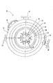
図1には本願発明による注入装置10が示されており、それは燃焼室100 に流体を注入するために使用される。注入装置10は燃焼室100 の方向を向いている注入装置前面12を有する注入装置本体14を有している。注入装置本体14はまた複数のジェット20, 32, 52を含み、以下説明するように1以上の入口18, 34, 54に流体が接続されている。流体は入口18, 34, 54を通って注入装置本体14に入り、ジェット20, 32, 52を通って燃焼室中に注入される。第1のスリーブ80は中空円筒管として示されており、注入装置本体14を囲んでおり、燃焼室100 の一部を構成している。第1の環状空間82は注入装置本体14の外面と第1のスリーブ80の内面との間を規定している。第1の環状空間82に接続されたリサイクルガス入口84は環状空間82を通って第1の環状空間82の周囲内側および燃焼室100 にリサイクルガスを供給する。
FIG. 1 shows an
燃焼室100 で行われる燃焼は燃料と酸素の燃焼である。燃料は例えば、メタン、エタン、プロパン、または炭化水素混合物のような炭素を含むガスであり、天然油またはバイオマス燃料から導出されることもできる。2つの有効な燃料はメタンおよび合成ガスすなわちsyngasであり、それは水素と1酸化炭素とを含んでいる。炭素を含む燃料は液体、気体或いはそれらの相の組合わせであってもよい。酸素は酸化流体で供給される。本発明の有効な1実施例では、炭素を含む燃料と酸素は実質上窒素および硫黄を含まない気体として供給される。この明細書の記載において、“実質上窒素および硫黄を含まない”とは窒素および硫黄を組合わせて重量で0.1%より少ない、好ましくは0.01%より少ない含有量であることを意味する。酸素は技術的に知られている任意の方法で大気中の空気から分離されることができ、微量のアルゴンのようなガスを含んでいてもよい。
燃 焼 The combustion performed in the
燃焼室100 における燃料と酸素との燃焼は燃焼ガスを発生し、温度とガス容積を増加させ、それに対応して圧力を増加させる。燃焼したガスはタービンのようなパワー取出し装置へ放出され、有効なエネルギが使用または貯蔵のために発生される。例えばタービンは発電機に結合されてそれを回転させて電力を発生する。
燃 焼 The combustion of fuel and oxygen in the
図2に示されるように、酸化流体は主入口18を通って注入装置本体の主孔16に供給される。酸化流体は主孔16から注入装置前面12を通過し、複数の主ジェット20により燃焼室100 に流れる。例示された実施例では6個の主ジェット20が示されているが、任意の数のジェット20が設けられることができる。主ジェット20の直径は、主ジェット20を通る酸化流体の予め定められた流量率が燃焼室100 中の圧力よりも予め定められた圧力だけ高い圧力で酸化流体を主入口18に供給することにより達成される。有効な1実施例において、各主ジェット20は注入装置前面で1インチ以上の直径を有し、各主ジェット20の中心は他の主ジェット20の中心から約4インチ以上の間隔である。酸化流体は主ジェット20から放射されたストリームとして燃焼室100 に流入し、それは図示された実施例においは注入装置本体14の主孔16を通って長手方向に延在する中心軸にほぼ平行に方向付けされている。
酸化 As shown in FIG. 2, the oxidizing fluid is supplied to the
第1の燃料は第1の燃料入口34に入り、第1の燃料供給管38を通って第1の燃料マニホルド30へ流れる。第1の燃料マニホルド30は注入装置本体14により規定された内部空間であり、燃料供給管38に連結され、したがって第1の燃料入口34および第1の燃料ジェット32に接続されている。示された実施例の第1の燃料マニホルド30は、図2および4に示されているように主ジェット18を囲んで延在する環状室42と主ジェット18に対して中心に位置する中心室40との両者を有している。中心室40と環状室42とはトンネル(図示せず)によって連結され、それは主ジェット18に対してほぼ垂直である。第1の燃料マニホルド30、燃料供給管38、および第1の燃料入口34と、第1の燃料入口34に燃料源を接続する構造、形状には多くの別の形態が存在することを認識すべきである。
The first fuel enters the
第1の燃料は第1の燃料ジェット32から燃焼室100 に放出される。図示の実施例では、24個の第1の燃料ジェットが設けられ、4個は主ジェット20のそれぞれの周囲に間隔を有して位置されているが、任意の数の第1の燃料ジェット32が設けられることができる。第1の燃料ジェット32のそれぞれは、第1の燃料ジェット32のそれぞれの中心軸が燃焼室100 中で各主ジェット20の中心軸に収斂して第1の燃料ジェット32から放出された燃料が各主ジェット20から放出されて流れる酸化流体流に衝突するように構成されている。
(1) The first fuel is discharged from the
第1の燃料と同様に、第2の燃料は第2の燃料入口54から入り、第2の燃料供給管(図示せず)を通って第2の燃料マニホルド50へ流れる。第2の燃料マニホルド50は注入装置本体14により規定された内部空間であり、第2の燃料供給管に連結され、したがって第2の燃料入口54および第2の燃料ジェット52に接続されている。図4に示されているように実施例の第2の燃料マニホルド50は主ジェット20の1つを囲んでそれぞれ延在する6個の環状室を有している。環状室はトンネル(図示せず)によって相互に連結され、それは主ジェット20に対してほぼ垂直に延在している。図示された実施例では、24個の第2の燃料ジェットが設けられ、4個は主ジェット20のそれぞれの周囲に間隔を有して位置されている。第2の燃料ジェット52のそれぞれは第2の燃料ジェット52のそれぞれの中心軸が燃焼室100 中の各主ジェット20の中心軸に収斂して第2の燃料ジェット52から放出された燃料が各主ジェット20から放出されて流れる酸化流体流に衝突するように構成されている。
As with the first fuel, the second fuel enters through a
各燃料ジェット32, 52と主ジェット20との間の収斂角度は燃料が酸化流体と混合される量および燃焼を生じさせるために燃料と酸化流体が十分に混合される燃焼室100 中の位置に影響を与える。各燃料ジェット32, 52と主ジェット20との間の距離もまた燃料と酸化流体の混合に影響する。燃料と酸化流体の混合および燃焼が注入装置前面12に近い位置で生じた場合には、注入装置前面12と注入装置10は燃焼によって発生された熱にさらされ、付加的な冷却が必要になる。本発明の有効な1実施例では、第1および第2の燃料ジェット32, 52のそれぞれは主ジェット20の1つに対して約10度乃至45度の収斂角度を有している。別の実施例では、燃料ジェットは燃料ジェット32, 52から放出される燃料が注入装置前面12の約2インチ以内の位置にある領域で各主ジェット20からの酸化流体流に衝突するように構成されている。したがって、燃料ジェット32, 52から放出される燃料は酸化流体と混合されて燃料の均一な燃焼が容易に可能になる。しかしながら、燃料はジェット20, 32, 52に近接した位置で混合および燃焼されないで燃焼は注入装置10中で発生する。
The angle of convergence between each
第1および第2の燃料ジェット32, 52の配置は図3に示されている。各主ジェット20に対して単一の第1および第2の燃料ジェット32, 52を使用する場合を含めて任意の数の第1および第2の燃料ジェット32, 52が設けられることが可能であることが認識されるであろう。第1および第2の燃料ジェット32, 52は主ジェット20を中心に対称的に配置されることが好ましいが、非対称的な配置もまた可能である。また、示された燃料ジェット32, 52は円形断面を有しているが、他の形状もまた可能である。例えば、第1および第2の燃料ジェット32, 52の一方または両方は、主ジェット20の全てまたは一部を囲んでその周囲に延在するスロットを規定する単一のジェットであってもよい。さらに図3は第1の燃料ジェット32と第2の燃料ジェット52との断面寸法の相違を示している。任意の寸法の燃料ジェット32, 52が使用できるが、燃料ジェット32, 52の寸法は燃料の加熱値、動作圧力、燃料ジェット32, 52の数を考慮に入れて選択することが好ましい。例えば、燃料ジェット32, 52の直径は所望の燃焼に対する燃料の必要な質量流量率および酸化流体との適切な混合のために燃焼100 中への燃料の必要なモーメントにしたがって計算されることができる。異なった燃料の必要な質量流量率は燃料の加熱値にしたがって変化させることができる。もっとも、酸化流体と各燃料との適切な混合を確実にするために類似するモーメントを有する異なった燃料を注入することが好ましい。したがって、異なった寸法の燃料ジェット32, 52は異なった燃料の使用を可能にし、一方で同じレートの熱発生および同じ燃料モーメントを維持する。例えば、図3に示された実施例では、第1の燃料ジェット32は第2の燃料ジェット52の約3倍の直径を有する。すなわち、第1の燃料ジェット32が第2の燃料の加熱値の約1/3の加熱値を有する第1の燃料に対して使用され、2つの燃料が等しい密度を有し、類似したモーメントで注入されれば2つの燃料によって発生される熱の量は類似したものとなるであろう。
The arrangement of the first and
注入装置10とジェット20, 32, 52の相対的な寸法もまた図3に示されている。1実施例では、注入装置10の直径は約12.5インチであり、燃料ジェット20, 32, 52の直径は約0.1インチである。主ジェット20は注入装置前面12で直径が約1インチであり、各主ジェット20の中心は他の主ジェット20の中心から約4インチ以上の距離である。
The relative dimensions of the
本発明の有効な1実施例では、第2の燃料ジェット52は約90%がメタンである自然ガスを注入するために使用される。第1の燃料ジェット32は1酸化炭素、水素、および2酸化炭素からなる合成ガスを注入するために使用される。合成ガスは石油コークス(petcoke) のガス化のためにスチームと酸素を使用して発生されることができ、それは重量で約90%の固体カーボンと水蒸気および灰分である。第1の燃料と第2の燃料とは同時に注入されることができるが、本発明の好ましい1実施例では一時に第1と第2のガスの一方だけが注入される。すなわち、燃焼に使用される燃料ガスは注入装置10を変更することなく変更され、利用可能性、価格、効率等の他の基準にしたがって選択されることができる。さらに、注入装置10の多能性を改善するために付加的なジェットが設けられることができることを理解すべきである。例えば、注入装置10は対応する燃料マニホルドと入口とを有する第3のセットの燃料ジェットを含むことができ、したがって、第3の燃料ソースを独立に燃焼室100 に供給することができる。第1と第2の複数の燃料ジェット32および52と、任意の追加の燃料ジェットのそれぞれの構成は特定の条件下で特定のタイプのガスの注入に対して調整されることができる。例えば、第1の燃料ジェット32の数および寸法、第1の燃料ジェット32と主ジェット20との間の間隔および角度は第1の燃料ジェット32を通る特定の燃料、例えば水素と1酸化炭素を含む合成ガスの注入に対して特別に調整されることができる。同様に第2の燃料ジェット52および追加の燃料ジェットのセットはメタンまたは自然ガスのような他の燃料に対して構成されることができる。
In one advantageous embodiment of the present invention, the
図1および2に示されるように、第2のスリーブ90は第1のスリーブ80を囲んで配置され、2つのスリーブ80,90間に第2の環状空間94を規定している。第2の環状空間94は周囲通路86に接続され、この周囲通路86は第2のスリーブ90の周囲に延在して希釈ガス入口84に接続されている。希釈ガス入口84は希釈ガスのソース(図示せず)に連結されている。したがって、希釈ガスは希釈ガス入口84に入り、周囲通路86を通り、第2のスリーブ孔を通って第2の環状空間94に流れる。希釈ガスは第2の環状空間94を通ってジェット20, 32, 52の酸化流体および燃料の方向とはほぼ反対の方向に流れる。第2の環状空間94から希釈ガスは第2の環状空間94および第1の環状空間82に接続されている複数の第1のスリーブ孔88を通って流れる。第1の環状空間82において、希釈ガスはその流れる方向を反転して燃焼室100 の方向に流れ、そこで燃焼ガスと混合されて燃焼ガスの一部となる。希釈ガスは燃焼ガスを希釈して燃焼温度を適度にする。液体の希釈剤も使用可能であるが、ガス希釈剤が好ましい。種々の希釈ガスず使用可能であり、有用な1実施例では燃焼室100 からの燃焼ガスが膨張されたタービンからのリサイクルガスが含まれている。リサイクルガスはスチームと2酸化炭素から構成されている。リサイクルガスにより行われる冷却の程度は燃焼温度、燃焼室100 に流れるガスの流量率、リサイクルガスの温度、およびリサイクルガスの組成に依存している。燃焼室100 の温度は少なくとも約4000度Fに減少されることが好ましく、最も好ましいのは約2000度Fである。
As shown in FIGS. 1 and 2, the
注入装置10はまた冷却体室(図示せず)を通って流れる水のような冷却流体によって冷却されてもよい。冷却体室は注入装置本体10によって規定された内部ギャップであり、それは冷却体入口72および冷却体出口74に連結されている。冷却流体は冷却剤入口72にポンプではいいそれ、冷却剤出口74から放出される。種々の形態の冷却体室が既知の技術により使用されることができる。
The
本発明の有効な1実施例において、注入装置10は燃焼室100 にガスを注入するために使用され、それはガスと適合する。例えば、注入装置10は発電プラント中でガスを燃焼するために使用される再ヒータ中に炭素含有ガス、酸素ガスおよびスチームと2酸化炭素の混合物を注入するために使用される。再ヒータはここで参考文献とされる米国特許出願中に記載されているガス発電機およびタービンから放出される燃焼ガスを再燃焼することができる。その代わりに再ヒータは例えば図5に示されているパワー発生サイクルにおける最初の燃焼装置であってもよい。
In one advantageous embodiment of the invention, the
図5に示されているパワー発生サイクルは再ヒータ140 を含み、それは燃焼のために酸素および例えば合成ガスのような炭素含有ガスを受取る。酸素は空気分離装置110 中で発生され、それは空気から窒素の少なくともほとんどを除去して、窒素と硫黄を実質上含まない酸素を放出する。窒素は当業者に知られているように超低温プロセスを使用して除去されることができる。その場合に、そのプロセスから得られた超低温窒素は売却され、或いはパワー発生サイクルの次の冷却プロセスで使用されることができる。他の実施例では酸化流体は空気分離装置110 以外の供給源、例えば貯蔵タンク、配送パイプライン、或いはその他の当業者に知られている酸素発生装置から供給されることができる。
パ ワ ー The power generation cycle shown in FIG. 5 includes a
図5に示されている実施形態では、合成ガスは合成ガス発生装置120 によって発生される。合成ガス発生装置120 は単なる例示として示されており、合成ガスは技術的に知られている他のプロセスによって得られることができる。さらに、合成ガス以外の他の燃焼ガスが使用されてもよい。例えば、燃焼ガスはメタン、エタン、プロパンまたは炭化水素混合物で構成され、天然油またはバイオマス燃料から得られてもよい。
In the embodiment shown in FIG. 5, the syngas is generated by a
酸化流体はコンプレッサ112, 114によって圧縮され、再ヒータ140 および合成ガス発生装置120 に供給される。合成ガス発生装置120 は水および石油コークス源122, 124から水および石油コークスを受取る気化装置126 を含んでいる。石油コークスは気化装置126 中で気化されて排気ガスを形成し、その排気ガスは技術的に知られているように合成ガスを含んでいる。合成ガスは水素、1酸化炭素および2酸化炭素を含み、この実施例では特に約50%の1酸化炭素、34.2%の水素、および15.8%の2酸化炭素を含んでいる。合成ガスは高温の熱再生装置128 および低温の熱再生装置130 を通り、それら両者は以下説明するように熱再生スチーム発生装置150 に結合されている。
The oxidizing fluid is compressed by the
合成ガスはその後、再ヒータ140 に放出される。合成ガスは注入装置10を通って再ヒータ140 に酸素および希釈剤と共に入る。希釈剤はスチームおよび2酸化炭素を含むリサイクルガスである。希釈剤は再ヒータ140 中の酸素を希釈して再ヒータ140 中の温度を制限する。生成ガスは再ヒータ140 の燃焼室100 中で燃焼され、燃焼されたガスまたは燃焼生成物を形成し、それは1次タービン142 に放出される。燃焼生成物は1次タービン142 中で膨張され、エネルギが発生されて機械的または水力学的に1次タービン142 に結合されている発電機146 を回転させる。1次タービン142 からの燃焼生成物は熱再生スチーム発生装置150 に放出され、そこで燃焼生成物は冷却される。熱再生スチーム発生装置150 は1次タービン142 から放出された燃焼生成物の熱エネルギを使用することにより熱交換機として動作し、高温の熱再生装置128 からの中間排気ガスを加熱する。この中間排気ガスは第1のタービン160 に放出される。中間排気ガスは第1のタービン160 から熱再生スチーム発生装置150 に放出され、そこで再加熱されて第2のタービン162 に供給され、それから第3のタービン164 に供給される。中間排気ガスはタービン160, 162, 164 において膨張され、中間排気ガスの温度および圧力は減少する。タービン160, 162, 164 の動作圧力はその結果減少して、それにより第2のタービン162 は第1のタービン160 より低く、第3のタービン164 よりも高い圧力で動作する。タービン160, 162, 164 は発電機166 に結合され、この発電機166 はタービン160, 162, 164 によって回転され、電力を発生する。続いて中間排気ガスはコンデンサ168 およびポンプ170 に放出され、それは凝縮された排気ガスを合成ガス発生装置120 に戻す。
The synthesis gas is then discharged to the
燃焼生成物は熱再生スチーム発生装置150 中で冷却される。燃焼生成物の第1の部分は熱再生スチーム発生装置150 からコンプレッサ144 にリサイクルされ、コンプレッサ144 は燃焼生成物を圧縮して燃焼生成物を希釈剤として再ヒータ140 に供給する。ブリード線148 はコンプレッサ144 を1次タービン142 に接続している。コンプレッサ144 は1次タービン142 を発電機146 に機械的に結合されているシャフトによって駆動される。図示されていないが、単一の駆動シャフトが全てのタービン142, 160, 162, 164によって駆動され、同じシャフトがコンプレッサ144 も駆動している。図5の実施例において、希釈剤はほぼ67%のスチームと33%の2酸化炭素からなるが実際の割合は変化させることができる。
The combustion products are cooled in the heat
燃焼生成物の第2の部分は高圧コンプレッサ172 に供給され、そこで燃焼生成物中の2酸化炭素は圧縮されて液化される。2酸化炭素はその後2酸化炭素出口174 から放出され、水は水出口176 から放出される。2酸化炭素と水は発電サイクルの他の部分で使用するためにリサイクルされてもよい。
The second portion of the combustion products is supplied to the
以上の説明および関連した図面の説明から本発明の多くの変形および実施形態が当業者には想定されるであろう。したがって、本発明は開示された特定の実施形態に限定されるものではなく、そのような変形および実施形態は特許請求の範囲に記載された本発明の技術的範囲に含まれることを意図するものである。ここで特定の用語が使用されているが、それらは一般的な意味で、記述に使用されており、本発明の技術的範囲を限定することを意図しているものではない。 Many variations and embodiments of the invention will occur to those skilled in the art from the foregoing description and the description of the associated figures. Therefore, it is intended that the invention not be limited to the particular embodiments disclosed, but that such variations and embodiments will fall within the scope of the invention as set forth in the appended claims. It is. Although specific terms are used herein, they are used in a generic sense, and are not intended to limit the scope of the invention.
Claims (31)
注入装置本体および第1のスリーブを具備し、この注入装置本体と第1のスリーブとの間に第1の環状空間が形成されており、
前記注入装置本体は燃焼室に面した注入装置前面と、主孔と、前記注入装置前面から主孔まで延在している1以上の主ジェットとを具備し、
さらに、前記注入装置本体は注入装置前面に開口している第1の複数の燃料ジェットおよび第2の複数の燃料ジェットと、第1の複数の燃料ジェットに燃料を供給するように連結された第1の燃料入口と、第2の複数の燃料ジェットに燃料を供給するように連結された第2の燃料入口とを具備している注入装置。 In an injection device for injecting a fuel fluid into a combustion chamber,
An injection device body and a first sleeve, wherein a first annular space is formed between the injection device body and the first sleeve;
The injector body includes an injector front facing the combustion chamber, a main hole, and one or more main jets extending from the injector front to the main hole;
Further, the injector body is connected to a first plurality of fuel jets and a second plurality of fuel jets opening at a front surface of the injector, and a fuel jet is connected to supply fuel to the first plurality of fuel jets. An injector comprising: a first fuel inlet; and a second fuel inlet coupled to supply fuel to a second plurality of fuel jets.
実質的に窒素および硫黄を含まない酸素から構成されている少なくとも1つの酸化流体を燃焼室に注入し、
第1の複数の燃料ジェットを使用する第1の燃料流体の燃焼室への注入と、第2の複数の燃料ジェットを使用する第2の燃料流体の燃焼室への注入とを交互に行って第1および第2の燃料流体を燃焼室中において酸化流体流に衝突させ、
酸化流体により燃料流体を燃焼させる方法。 In a method of injecting a fuel fluid into a combustion chamber and burning,
Injecting at least one oxidizing fluid comprising oxygen substantially free of nitrogen and sulfur into the combustion chamber;
Injecting a first fuel fluid into the combustion chamber using the first plurality of fuel jets and injecting a second fuel fluid into the combustion chamber using the second plurality of fuel jets alternately Impacting the first and second fuel fluids with the oxidizing fluid stream in the combustion chamber;
A method of burning a fuel fluid with an oxidizing fluid.
Applications Claiming Priority (1)
| Application Number | Priority Date | Filing Date | Title |
|---|---|---|---|
| US10/242,341 US6802178B2 (en) | 2002-09-12 | 2002-09-12 | Fluid injection and injection method |
Publications (2)
| Publication Number | Publication Date |
|---|---|
| JP2004101175A true JP2004101175A (en) | 2004-04-02 |
| JP2004101175A5 JP2004101175A5 (en) | 2005-09-29 |
Family
ID=31887775
Family Applications (1)
| Application Number | Title | Priority Date | Filing Date |
|---|---|---|---|
| JP2003321695A Pending JP2004101175A (en) | 2002-09-12 | 2003-09-12 | Fluid injection device and fluid injection method |
Country Status (5)
| Country | Link |
|---|---|
| US (2) | US6802178B2 (en) |
| EP (1) | EP1398566B1 (en) |
| JP (1) | JP2004101175A (en) |
| CN (1) | CN1506612A (en) |
| DE (1) | DE60329895D1 (en) |
Cited By (4)
| Publication number | Priority date | Publication date | Assignee | Title |
|---|---|---|---|---|
| JP2007183094A (en) * | 2006-01-09 | 2007-07-19 | Snecma | Cooling of multiple-mode fuel injector for combustion chamber, in particular of jet engine |
| JP2008089297A (en) * | 2006-10-02 | 2008-04-17 | General Electric Co <Ge> | Device for operating turbine engine |
| JP2010048542A (en) * | 2008-08-08 | 2010-03-04 | General Electric Co <Ge> | Lean direct injection diffusion chip and related method |
| JP2010511830A (en) * | 2006-12-04 | 2010-04-15 | ファイアースター エンジニアリング,エルエルシー | Spark-integrated propellant injector head with flashback barrier |
Families Citing this family (73)
| Publication number | Priority date | Publication date | Assignee | Title |
|---|---|---|---|---|
| US7962408B2 (en) * | 1999-11-05 | 2011-06-14 | American Express Travel Related Services Company, Inc. | Systems and methods for establishing an allocation of an amount between transaction accounts |
| US20050034446A1 (en) * | 2003-08-11 | 2005-02-17 | Fielder William Sheridan | Dual capture jet turbine and steam generator |
| US7287382B2 (en) * | 2004-07-19 | 2007-10-30 | John Henriquez | Gas turbine combustor end cover |
| US7836699B2 (en) * | 2005-12-20 | 2010-11-23 | United Technologies Corporation | Combustor nozzle |
| US7722690B2 (en) * | 2006-09-29 | 2010-05-25 | Kellogg Brown & Root Llc | Methods for producing synthesis gas |
| US8888875B2 (en) * | 2006-12-28 | 2014-11-18 | Kellogg Brown & Root Llc | Methods for feedstock pretreatment and transport to gasification |
| US7879119B2 (en) * | 2007-07-20 | 2011-02-01 | Kellogg Brown & Root Llc | Heat integration and condensate treatment in a shift feed gas saturator |
| CA2645954C (en) * | 2007-12-06 | 2012-09-04 | Rolls-Royce Power Engineering Plc | Radial staging method and configuration of a liquid injection system for power plants |
| US8221513B2 (en) * | 2008-01-29 | 2012-07-17 | Kellogg Brown & Root Llc | Low oxygen carrier fluid with heating value for feed to transport gasification |
| US20090274594A1 (en) * | 2008-04-30 | 2009-11-05 | Cliff Yi Guo | Methods and systems for feed injector multi-cooling channel |
| DE102008026459A1 (en) * | 2008-06-03 | 2009-12-10 | E.On Ruhrgas Ag | Burner for combustion device in gas turbine system, has plate shaped element arranged in fuel injector, and including fuel passage openings that are arranged in rings and displaced to each other in radial direction |
| US9157042B2 (en) | 2008-07-16 | 2015-10-13 | Kellogg Brown & Root Llc | Systems and methods for producing substitute natural gas |
| US9157043B2 (en) | 2008-07-16 | 2015-10-13 | Kellogg Brown & Root Llc | Systems and methods for producing substitute natural gas |
| US7955403B2 (en) * | 2008-07-16 | 2011-06-07 | Kellogg Brown & Root Llc | Systems and methods for producing substitute natural gas |
| US9132401B2 (en) | 2008-07-16 | 2015-09-15 | Kellog Brown & Root Llc | Systems and methods for producing substitute natural gas |
| US20100132257A1 (en) * | 2008-12-01 | 2010-06-03 | Kellogg Brown & Root Llc | Systems and Methods for Increasing Carbon Dioxide in Gasification |
| US8479519B2 (en) * | 2009-01-07 | 2013-07-09 | General Electric Company | Method and apparatus to facilitate cooling of a diffusion tip within a gas turbine engine |
| JP5330838B2 (en) * | 2009-01-19 | 2013-10-30 | 新日鉄住金エンジニアリング株式会社 | Combustion burner for combustible gas generated from waste gasification |
| US10018115B2 (en) | 2009-02-26 | 2018-07-10 | 8 Rivers Capital, Llc | System and method for high efficiency power generation using a carbon dioxide circulating working fluid |
| US8596075B2 (en) | 2009-02-26 | 2013-12-03 | Palmer Labs, Llc | System and method for high efficiency power generation using a carbon dioxide circulating working fluid |
| ES2733083T3 (en) | 2009-02-26 | 2019-11-27 | 8 Rivers Capital Llc | Apparatus and method for burning a fuel at high pressure and high temperature, and associated system and device |
| CN102459850B (en) * | 2009-06-05 | 2015-05-20 | 埃克森美孚上游研究公司 | Combustor systems and methods for using same |
| EP2264370B1 (en) * | 2009-06-16 | 2012-10-10 | Siemens Aktiengesellschaft | Burner assembly for a firing assembly for firing fluid fuels and method for operating such a burner assembly |
| CA2775448C (en) * | 2009-07-17 | 2015-10-27 | World Energy Systems Incorporated | Method and apparatus for a downhole gas generator |
| US9340741B2 (en) * | 2009-09-09 | 2016-05-17 | Gas Technology Institute | Biomass torrefaction mill |
| US8468834B2 (en) * | 2010-02-12 | 2013-06-25 | General Electric Company | Fuel injector nozzle |
| US8555648B2 (en) * | 2010-02-12 | 2013-10-15 | General Electric Company | Fuel injector nozzle |
| US8584467B2 (en) * | 2010-02-12 | 2013-11-19 | General Electric Company | Method of controlling a combustor for a gas turbine |
| US8919673B2 (en) * | 2010-04-14 | 2014-12-30 | General Electric Company | Apparatus and method for a fuel nozzle |
| US9278362B2 (en) * | 2010-09-09 | 2016-03-08 | Wells Gelven Fractal Technology, Llc | Fractal orifice plate |
| US20120067054A1 (en) | 2010-09-21 | 2012-03-22 | Palmer Labs, Llc | High efficiency power production methods, assemblies, and systems |
| US8869889B2 (en) | 2010-09-21 | 2014-10-28 | Palmer Labs, Llc | Method of using carbon dioxide in recovery of formation deposits |
| CN102011650B (en) * | 2010-12-22 | 2013-10-02 | 吴银森 | Multipoint frequent-explosion hydrogen energy steam turbine |
| US9133405B2 (en) | 2010-12-30 | 2015-09-15 | Kellogg Brown & Root Llc | Systems and methods for gasifying a feedstock |
| US8365534B2 (en) * | 2011-03-15 | 2013-02-05 | General Electric Company | Gas turbine combustor having a fuel nozzle for flame anchoring |
| US9182122B2 (en) * | 2011-10-05 | 2015-11-10 | General Electric Company | Combustor and method for supplying flow to a combustor |
| EP2776692B1 (en) | 2011-11-02 | 2016-05-04 | 8 Rivers Capital, LLC | Power generating system and corresponding method |
| US20130160856A1 (en) * | 2011-12-22 | 2013-06-27 | General Electric Company | Multi-port injector system and method |
| US8776532B2 (en) | 2012-02-11 | 2014-07-15 | Palmer Labs, Llc | Partial oxidation reaction with closed cycle quench |
| CN102721082B (en) * | 2012-06-26 | 2014-08-20 | 哈尔滨工程大学 | Cracking-gas fuel injection device for chemical regenerative cycle |
| US8943833B2 (en) * | 2012-07-06 | 2015-02-03 | United Technologies Corporation | Fuel flexible fuel injector |
| US9803865B2 (en) * | 2012-12-28 | 2017-10-31 | General Electric Company | System and method for a turbine combustor |
| WO2014189602A2 (en) * | 2013-03-14 | 2014-11-27 | United Technologies Corporation | Hollow-wall heat shield for fuel injector component |
| JP6250332B2 (en) | 2013-08-27 | 2017-12-20 | 8 リバーズ キャピタル,エルエルシー | Gas turbine equipment |
| ITMI20131816A1 (en) * | 2013-10-31 | 2015-05-01 | Ansaldo Energia Spa | INJECTOR WITH A DOUBLE NOZZLE SPEAR GAS TURBINE SYSTEM, GAS TURBINE SYSTEM AND A GAS TURBINE FEEDING METHOD |
| US9989014B2 (en) | 2014-03-28 | 2018-06-05 | The Boeing Company | Premixed liquid propellant propulsion system and method with anti-flashback quenching liquid injector |
| TWI691644B (en) | 2014-07-08 | 2020-04-21 | 美商八河資本有限公司 | Method and system for power production with improved efficiency |
| KR102625300B1 (en) | 2014-09-09 | 2024-01-15 | 8 리버스 캐피탈, 엘엘씨 | Production of low pressure liquid carbon dioxide from a power production system and method |
| US11231224B2 (en) | 2014-09-09 | 2022-01-25 | 8 Rivers Capital, Llc | Production of low pressure liquid carbon dioxide from a power production system and method |
| MA40950A (en) | 2014-11-12 | 2017-09-19 | 8 Rivers Capital Llc | SUITABLE CONTROL SYSTEMS AND PROCEDURES FOR USE WITH POWER GENERATION SYSTEMS AND PROCESSES |
| US10961920B2 (en) | 2018-10-02 | 2021-03-30 | 8 Rivers Capital, Llc | Control systems and methods suitable for use with power production systems and methods |
| US11686258B2 (en) | 2014-11-12 | 2023-06-27 | 8 Rivers Capital, Llc | Control systems and methods suitable for use with power production systems and methods |
| DE102015205069B4 (en) * | 2015-03-20 | 2020-04-23 | Deutsches Zentrum für Luft- und Raumfahrt e.V. | Incinerator |
| FR3037059B1 (en) * | 2015-06-02 | 2017-06-16 | Saint-Gobain Emballage | SONIC INJECTION OVEN |
| AU2016277834B2 (en) | 2015-06-15 | 2020-04-09 | 8 Rivers Capital, Llc | System and method for startup of a power production plant |
| CN105020743B (en) * | 2015-07-15 | 2017-10-03 | 哈尔滨工程大学 | A kind of fuel autoxidation cracks axially staged combustion chamber |
| DE102015215203A1 (en) * | 2015-08-10 | 2017-02-16 | Siemens Aktiengesellschaft | Burner lance for a pilot burner |
| EP3417037B1 (en) | 2016-02-18 | 2020-04-08 | 8 Rivers Capital, LLC | System and method for power production including methanation |
| ES2960756T3 (en) | 2016-02-26 | 2024-03-06 | 8 Rivers Capital Llc | Systems and methods to control a power plant |
| CN109416001B (en) * | 2016-07-19 | 2021-09-28 | 航天喷气发动机洛克达因股份有限公司 | Injector element for rocket engines |
| JP7449090B2 (en) | 2016-09-13 | 2024-03-13 | 8 リバーズ キャピタル,エルエルシー | Systems and methods for power production using partial oxidation |
| CN111094720B (en) | 2017-08-28 | 2023-02-03 | 八河流资产有限责任公司 | Regenerative supercritical CO 2 Low level thermal optimization of power cycle |
| US11230996B2 (en) * | 2017-12-28 | 2022-01-25 | Tuskegee University | System and method for active injection into fluid streams |
| PL3759322T3 (en) | 2018-03-02 | 2024-03-18 | 8 Rivers Capital, Llc | Systems and methods for power production using a carbon dioxide working fluid |
| CN108504390A (en) * | 2018-03-30 | 2018-09-07 | 烟台龙源电力技术股份有限公司 | Coal pretreatment device, control method and boiler |
| CN109578167B (en) * | 2018-11-21 | 2019-12-13 | 中国人民解放军国防科技大学 | Engine injector and engine with same |
| CN111412069B (en) * | 2020-04-30 | 2021-05-18 | 四川华气动力有限责任公司 | Control method and control system for fuel gas heat value variable quantity |
| EP3910236B1 (en) * | 2020-05-15 | 2024-04-03 | L'air Liquide, Société Anonyme Pour L'Étude Et L'exploitation Des Procédés Georges Claude | Process burner and method for combustion of combustion gases containing carbon monoxide |
| AT524257B1 (en) * | 2020-10-07 | 2022-12-15 | Wienerberger Ag | CIRCULATION NOZZLE FOR A KILN |
| WO2022261057A1 (en) * | 2021-06-08 | 2022-12-15 | Hydrogen Technologies LLC | Burner assemblies and methods |
| US20230204215A1 (en) * | 2021-12-29 | 2023-06-29 | General Electric Company | Fuel nozzle and swirler |
| CN114893324A (en) * | 2022-06-08 | 2022-08-12 | 西北工业大学 | Double-component fuel injector for realizing two-phase rotary detonation initiation |
| CN115977803B (en) * | 2023-03-15 | 2023-06-09 | 成都流体动力创新中心 | Backflow-preventing injector capable of realizing multiple injection angles |
Family Cites Families (81)
| Publication number | Priority date | Publication date | Assignee | Title |
|---|---|---|---|---|
| BE490785A (en) | 1948-08-27 | 1949-08-23 | ||
| FR1087714A (en) | 1953-11-23 | 1955-02-28 | Spray method and device | |
| US2857204A (en) | 1955-09-01 | 1958-10-21 | Gen Electric | Fuel injector nozzle |
| US2930532A (en) | 1958-12-19 | 1960-03-29 | Oce W Johnson | Spray gun nozzle |
| US3093315A (en) | 1959-03-23 | 1963-06-11 | Tachiki Kenkichi | Atomization apparatus |
| US3056559A (en) | 1960-01-11 | 1962-10-02 | Orr Donald | Beverage dispenser |
| US3121639A (en) | 1960-10-19 | 1964-02-18 | Dairy Foods Inc | Spray drying process |
| US3430863A (en) | 1966-12-28 | 1969-03-04 | Us Army | Fuel-oxidizer injection |
| DE1903595A1 (en) | 1968-01-25 | 1969-10-09 | Daido Sanso Kabushiki Kaisha O | Method and apparatus for continuously generating a high temperature flame |
| US3603092A (en) * | 1969-09-24 | 1971-09-07 | Nasa | Injection head for delivering liquid fuel and oxidizers |
| US3928961A (en) | 1971-05-13 | 1975-12-30 | Engelhard Min & Chem | Catalytically-supported thermal combustion |
| US3816595A (en) | 1971-11-15 | 1974-06-11 | Aqua Chem Inc | Method and apparatus for removing nitrogen oxides from a gas stream |
| US3850569A (en) | 1971-12-29 | 1974-11-26 | Phillips Petroleum Co | Process for reducing nitric oxide emissions from burners |
| US3779212A (en) | 1972-05-12 | 1973-12-18 | Rockwell International Corp | Non-polluting steam generator system |
| US3729285A (en) | 1972-05-22 | 1973-04-24 | G Schwedersky | Burner and method of operating it to control the production of nitrogen oxides |
| US3923011A (en) | 1972-05-31 | 1975-12-02 | Engelhard Min & Chem | Apparatus and method |
| GB1465785A (en) | 1973-03-12 | 1977-03-02 | Tokyo Gas Co Ltd | Burner and method of combustion- |
| US4021186A (en) | 1974-06-19 | 1977-05-03 | Exxon Research And Engineering Company | Method and apparatus for reducing NOx from furnaces |
| US4173118A (en) | 1974-08-27 | 1979-11-06 | Mitsubishi Jukogyo Kabushiki Kaisha | Fuel combustion apparatus employing staged combustion |
| US4054407A (en) | 1975-12-29 | 1977-10-18 | Engelhard Minerals & Chemicals Corporation | Method of combusting nitrogen-containing fuels |
| US4041699A (en) | 1975-12-29 | 1977-08-16 | The Garrett Corporation | High temperature gas turbine |
| JPS5413020A (en) | 1977-06-30 | 1979-01-31 | Nippon Oxygen Co Ltd | Liquid fuel burner |
| US4271664A (en) | 1977-07-21 | 1981-06-09 | Hydragon Corporation | Turbine engine with exhaust gas recirculation |
| US4288408A (en) | 1978-07-07 | 1981-09-08 | L. A. Daly Company | Apparatus for the diacritic cracking of hydrocarbon feeds for the selective production of ethylene and synthesis gas |
| JPS5535885A (en) | 1978-09-06 | 1980-03-13 | Kobe Steel Ltd | Combustion method capable of minimizing production of nitrogen oxide and smoke |
| US4316580A (en) | 1979-07-13 | 1982-02-23 | Sontek Industries, Inc. | Apparatus for fragmenting fluid fuel to enhance exothermic reactions |
| US4356698A (en) | 1980-10-02 | 1982-11-02 | United Technologies Corporation | Staged combustor having aerodynamically separated combustion zones |
| US4407450A (en) | 1980-10-30 | 1983-10-04 | Chegolya Alexandr S | Method of aerodynamic production of liquid and solid disperse aerosols |
| US4504211A (en) | 1982-08-02 | 1985-03-12 | Phillips Petroleum Company | Combination of fuels |
| DE3317035A1 (en) * | 1983-05-10 | 1984-11-15 | BBC Aktiengesellschaft Brown, Boveri & Cie., Baden, Aargau | MULTIPLE BURNER |
| DE3327597A1 (en) | 1983-07-30 | 1985-02-07 | Deutsche Babcock Werke AG, 4200 Oberhausen | METHOD AND BURNER FOR BURNING LIQUID OR GASEOUS FUELS WITH REDUCED NOX PRODUCTION |
| US4801092A (en) | 1986-02-24 | 1989-01-31 | Rockwell International Corporation | Injector assembly for a fluid fueled engine |
| JPS62289257A (en) | 1986-06-09 | 1987-12-16 | Ikeuchi:Kk | Hyperfine mist injection nozzle |
| US4784600A (en) | 1986-10-08 | 1988-11-15 | Prutech Ii | Low NOx staged combustor with swirl suppression |
| US4773596A (en) | 1987-04-06 | 1988-09-27 | United Technologies Corporation | Airblast fuel injector |
| US5029557A (en) | 1987-05-01 | 1991-07-09 | Donlee Technologies, Inc. | Cyclone combustion apparatus |
| US4912931A (en) | 1987-10-16 | 1990-04-03 | Prutech Ii | Staged low NOx gas turbine combustor |
| JPH01114623A (en) | 1987-10-27 | 1989-05-08 | Toshiba Corp | Gas turbine combustor |
| US4936088A (en) | 1987-11-18 | 1990-06-26 | Radian Corporation | Low NOX cogeneration process |
| US4893468A (en) | 1987-11-30 | 1990-01-16 | General Electric Company | Emissions control for gas turbine engine |
| US5042964A (en) | 1988-05-26 | 1991-08-27 | American Combustion, Inc. | Flash smelting furnace |
| US4989549A (en) | 1988-10-11 | 1991-02-05 | Donlee Technologies, Inc. | Ultra-low NOx combustion apparatus |
| US5103630A (en) | 1989-03-24 | 1992-04-14 | General Electric Company | Dry low NOx hydrocarbon combustion apparatus |
| US4958488A (en) | 1989-04-17 | 1990-09-25 | General Motors Corporation | Combustion system |
| US5158445A (en) | 1989-05-22 | 1992-10-27 | Institute Of Gas Technology | Ultra-low pollutant emission combustion method and apparatus |
| US5247791A (en) | 1989-10-25 | 1993-09-28 | Pyong S. Pak | Power generation plant and power generation method without emission of carbon dioxide |
| US5285628A (en) | 1990-01-18 | 1994-02-15 | Donlee Technologies, Inc. | Method of combustion and combustion apparatus to minimize Nox and CO emissions from a gas turbine |
| US5224333A (en) | 1990-03-13 | 1993-07-06 | Delavan Inc | Simplex airblast fuel injection |
| US5025631A (en) | 1990-07-16 | 1991-06-25 | Garbo Paul W | Cogeneration system with low NOx combustion of fuel gas |
| US5462430A (en) | 1991-05-23 | 1995-10-31 | Institute Of Gas Technology | Process and apparatus for cyclonic combustion |
| US5161379A (en) | 1991-12-23 | 1992-11-10 | United Technologies Corporation | Combustor injector face plate cooling scheme |
| US5222357A (en) * | 1992-01-21 | 1993-06-29 | Westinghouse Electric Corp. | Gas turbine dual fuel nozzle |
| US5259184A (en) | 1992-03-30 | 1993-11-09 | General Electric Company | Dry low NOx single stage dual mode combustor construction for a gas turbine |
| US5288021A (en) | 1992-08-03 | 1994-02-22 | Solar Turbines Incorporated | Injection nozzle tip cooling |
| IT1263683B (en) | 1992-08-21 | 1996-08-27 | Westinghouse Electric Corp | NOZZLE COMPLEX FOR FUEL FOR A GAS TURBINE |
| US5467926A (en) | 1994-02-10 | 1995-11-21 | Solar Turbines Incorporated | Injector having low tip temperature |
| GB2288640B (en) | 1994-04-16 | 1998-08-12 | Rolls Royce Plc | A gas turbine engine |
| EP0828929B1 (en) | 1994-08-25 | 2004-09-22 | Clean Energy Systems, Inc. | Reduced pollution power generation system and gas generator therefore |
| US6170264B1 (en) | 1997-09-22 | 2001-01-09 | Clean Energy Systems, Inc. | Hydrocarbon combustion power generation system with CO2 sequestration |
| US5778676A (en) | 1996-01-02 | 1998-07-14 | General Electric Company | Dual fuel mixer for gas turbine combustor |
| US5675971A (en) | 1996-01-02 | 1997-10-14 | General Electric Company | Dual fuel mixer for gas turbine combustor |
| US5680766A (en) | 1996-01-02 | 1997-10-28 | General Electric Company | Dual fuel mixer for gas turbine combustor |
| US5680765A (en) | 1996-01-05 | 1997-10-28 | Choi; Kyung J. | Lean direct wall fuel injection method and devices |
| US5950417A (en) | 1996-07-19 | 1999-09-14 | Foster Wheeler Energy International Inc. | Topping combustor for low oxygen vitiated air streams |
| US5713205A (en) | 1996-08-06 | 1998-02-03 | General Electric Co. | Air atomized discrete jet liquid fuel injector and method |
| US5806298A (en) * | 1996-09-20 | 1998-09-15 | Air Products And Chemicals, Inc. | Gas turbine operation with liquid fuel vaporization |
| US5906806A (en) | 1996-10-16 | 1999-05-25 | Clark; Steve L. | Reduced emission combustion process with resource conservation and recovery options "ZEROS" zero-emission energy recycling oxidation system |
| US5906094A (en) | 1997-04-30 | 1999-05-25 | Siemens Westinghouse Power Corporation | Partial oxidation power plants and methods thereof |
| EP0875719B1 (en) | 1997-05-01 | 2001-10-24 | Haldor Topsoe A/S | Swirling-flow burner |
| US5850732A (en) | 1997-05-13 | 1998-12-22 | Capstone Turbine Corporation | Low emissions combustion system for a gas turbine engine |
| US5934064A (en) | 1997-05-13 | 1999-08-10 | Siemens Westinghouse Power Corporation | Partial oxidation power plant with reheating and method thereof |
| US5966926A (en) | 1997-05-28 | 1999-10-19 | Capstone Turbine Corporation | Liquid fuel injector purge system |
| US5833141A (en) | 1997-05-30 | 1998-11-10 | General Electric Company | Anti-coking dual-fuel nozzle for a gas turbine combustor |
| AU739352B2 (en) | 1997-06-06 | 2001-10-11 | Texaco Development Corporation | Floating pressure gasifier feed injector cooling water system |
| US5966937A (en) | 1997-10-09 | 1999-10-19 | United Technologies Corporation | Radial inlet swirler with twisted vanes for fuel injector |
| DE59811106D1 (en) * | 1998-02-25 | 2004-05-06 | Alstom Technology Ltd Baden | Power plant and method for operating a power plant with a CO2 process |
| US6148602A (en) | 1998-08-12 | 2000-11-21 | Norther Research & Engineering Corporation | Solid-fueled power generation system with carbon dioxide sequestration and method therefor |
| JP3457907B2 (en) | 1998-12-24 | 2003-10-20 | 三菱重工業株式会社 | Dual fuel nozzle |
| US6206684B1 (en) | 1999-01-22 | 2001-03-27 | Clean Energy Systems, Inc. | Steam generator injector |
| WO2001090548A1 (en) * | 2000-05-12 | 2001-11-29 | Clean Energy Systems, Inc. | Semi-closed brayton cycle gas turbine power systems |
| DE10064270A1 (en) * | 2000-12-22 | 2002-07-11 | Alstom Switzerland Ltd | Method for operating a gas turbine system and a related gas turbine system |
-
2002
- 2002-09-12 US US10/242,341 patent/US6802178B2/en not_active Expired - Lifetime
-
2003
- 2003-09-05 EP EP03020207A patent/EP1398566B1/en not_active Expired - Fee Related
- 2003-09-05 DE DE60329895T patent/DE60329895D1/en not_active Expired - Lifetime
- 2003-09-12 CN CNA031649300A patent/CN1506612A/en active Pending
- 2003-09-12 JP JP2003321695A patent/JP2004101175A/en active Pending
-
2004
- 2004-03-26 US US10/811,203 patent/US6857274B2/en not_active Expired - Fee Related
Cited By (4)
| Publication number | Priority date | Publication date | Assignee | Title |
|---|---|---|---|---|
| JP2007183094A (en) * | 2006-01-09 | 2007-07-19 | Snecma | Cooling of multiple-mode fuel injector for combustion chamber, in particular of jet engine |
| JP2008089297A (en) * | 2006-10-02 | 2008-04-17 | General Electric Co <Ge> | Device for operating turbine engine |
| JP2010511830A (en) * | 2006-12-04 | 2010-04-15 | ファイアースター エンジニアリング,エルエルシー | Spark-integrated propellant injector head with flashback barrier |
| JP2010048542A (en) * | 2008-08-08 | 2010-03-04 | General Electric Co <Ge> | Lean direct injection diffusion chip and related method |
Also Published As
| Publication number | Publication date |
|---|---|
| EP1398566A2 (en) | 2004-03-17 |
| EP1398566A3 (en) | 2004-03-31 |
| US20040177619A1 (en) | 2004-09-16 |
| US20040050070A1 (en) | 2004-03-18 |
| CN1506612A (en) | 2004-06-23 |
| DE60329895D1 (en) | 2009-12-17 |
| US6802178B2 (en) | 2004-10-12 |
| EP1398566B1 (en) | 2009-11-04 |
| US6857274B2 (en) | 2005-02-22 |
Similar Documents
| Publication | Publication Date | Title |
|---|---|---|
| JP2004101175A (en) | Fluid injection device and fluid injection method | |
| CN101865470B (en) | Gas turbine premixer with internal cooling | |
| US6755359B2 (en) | Fluid mixing injector and method | |
| US8112999B2 (en) | Turbomachine injection nozzle including a coolant delivery system | |
| US4893468A (en) | Emissions control for gas turbine engine | |
| US8375724B2 (en) | Method of operating a multi-fuel combustion system | |
| JP5921630B2 (en) | How to operate a co-firing system | |
| CN101776015A (en) | Premixed partial oxidation syngas generation and gas turbine system | |
| JP2004325068A (en) | Differential pressure guidance purging type fuel injector with asymmetric cyclone | |
| CN110662922B (en) | System and method for combustion of solid fuels and derivatives thereof | |
| JP2009047415A (en) | Turbine engine fuel supply device and system | |
| WO2016056579A1 (en) | Combustor and gas turbine engine | |
| JP2018508735A (en) | System and method for high volume oxidant flow in a gas turbine engine with exhaust recirculation | |
| WO2009035334A1 (en) | Device and method for mixing at least two fluid flows for combustion | |
| JP2011141112A (en) | Apparatus and method for supplying fuel | |
| KR20160125916A (en) | System and method having fuel nozzle | |
| CN101876451A (en) | Be used to control the system and method for combustion dynamics | |
| JP2011112286A (en) | Gas turbine combustor | |
| EP3336330B1 (en) | Methods for startup and operation of gas turbine combined cycle power plants using nmhc fuels | |
| JP2021524011A (en) | Systems and methods to improve combustion stability in gas turbines | |
| JP5555724B2 (en) | Power generation system | |
| US20120312889A1 (en) | Injector tip assembly and method of fuel injection | |
| KR20230114995A (en) | Combustor replaceable for each unit cluster and gas turbine including the same | |
| CN116772234A (en) | Fuel supply system for a burner |
Legal Events
| Date | Code | Title | Description |
|---|---|---|---|
| A521 | Written amendment |
Free format text: JAPANESE INTERMEDIATE CODE: A523 Effective date: 20050722 |
|
| A621 | Written request for application examination |
Free format text: JAPANESE INTERMEDIATE CODE: A621 Effective date: 20060705 |
|
| A131 | Notification of reasons for refusal |
Free format text: JAPANESE INTERMEDIATE CODE: A131 Effective date: 20081209 |
|
| A601 | Written request for extension of time |
Free format text: JAPANESE INTERMEDIATE CODE: A601 Effective date: 20090309 |
|
| A602 | Written permission of extension of time |
Free format text: JAPANESE INTERMEDIATE CODE: A602 Effective date: 20090312 |
|
| A02 | Decision of refusal |
Free format text: JAPANESE INTERMEDIATE CODE: A02 Effective date: 20090901 |