JP2004096227A - Sound processing apparatus and method therefor, computer program, and computer readable storage medium - Google Patents
Sound processing apparatus and method therefor, computer program, and computer readable storage medium Download PDFInfo
- Publication number
- JP2004096227A JP2004096227A JP2002251709A JP2002251709A JP2004096227A JP 2004096227 A JP2004096227 A JP 2004096227A JP 2002251709 A JP2002251709 A JP 2002251709A JP 2002251709 A JP2002251709 A JP 2002251709A JP 2004096227 A JP2004096227 A JP 2004096227A
- Authority
- JP
- Japan
- Prior art keywords
- recording
- sound
- time
- recording time
- display
- Prior art date
- Legal status (The legal status is an assumption and is not a legal conclusion. Google has not performed a legal analysis and makes no representation as to the accuracy of the status listed.)
- Pending
Links
Images


Classifications
-
- G—PHYSICS
- G10—MUSICAL INSTRUMENTS; ACOUSTICS
- G10L—SPEECH ANALYSIS OR SYNTHESIS; SPEECH RECOGNITION; SPEECH OR VOICE PROCESSING; SPEECH OR AUDIO CODING OR DECODING
- G10L25/00—Speech or voice analysis techniques not restricted to a single one of groups G10L15/00 - G10L21/00
- G10L25/48—Speech or voice analysis techniques not restricted to a single one of groups G10L15/00 - G10L21/00 specially adapted for particular use
-
- G—PHYSICS
- G10—MUSICAL INSTRUMENTS; ACOUSTICS
- G10L—SPEECH ANALYSIS OR SYNTHESIS; SPEECH RECOGNITION; SPEECH OR VOICE PROCESSING; SPEECH OR AUDIO CODING OR DECODING
- G10L19/00—Speech or audio signals analysis-synthesis techniques for redundancy reduction, e.g. in vocoders; Coding or decoding of speech or audio signals, using source filter models or psychoacoustic analysis
- G10L19/018—Audio watermarking, i.e. embedding inaudible data in the audio signal
Abstract
Description
【0001】
【発明の属する技術分野】
本発明は、動画像を撮像、記録、再生する撮像装置等に用いられる音声処理装置、方法、コンピュータプログラム、及びコンピュータ読み取り可能な記憶媒体に関する。
【0002】
【従来の技術】
従来、固体メモリ素子を有するメモリカードを記録媒体として、静止画像や動画像を記録再生する電子カメラは既に市販されており、カラー液晶パネル等の電子ファインダを備える電子カメラも販売されている。これらの電子カメラによれば、撮影前の画像を連続して表示して電子カメラの使用者が構図を決定することや、撮影した画像を再生表示して確認することが可能である。特に、撮影した画像を撮影直後に再生する機能は利便性が高く、電子カメラの使用者にとって有益な機能となっている。
【0003】
また、デジタルカメラにおいても、静止画像のみならず動画像の撮影機能を持った製品も増えており、動画像の録画時間や画像サイズ等も向上している。このようなデジタルカメラの中には、マイクとスピーカを装備し、これらマイクとスピーカを利用した音声の録音・再生機能を持ったものもあり、アフレコや音声メモといった機能を有するものもある。
【0004】
他方、デジタルカメラの起動音や操作音に電子音だけでなく、スピーカから各種効果音を鳴らす機種も出てきている。これらの機種では、セルフタイマーでシャッタを押す際に「はい、チーズ」、「パシャッ」といった効果音を用いて撮影することが可能である。
【0005】
【発明が解決しようとする課題】
デジタルカメラの持つマイクとスピーカの機能を用い、録音した音声をデジタルカメラの操作音や起動音として利用することも可能となる。しかしながら、この場合、再生時間が極端に短いため、うまく録音することが難しいといった問題があった。アフレコ等で録音した音声を切り出して利用することも考えられるが、その場合は操作が複雑となりユーザによって分かりにくい機能となってしまう。
【0006】
本発明は上記課題に鑑みてなされたもので、例えばデジタルカメラ等の撮像装置の操作音や起動音として音声を録音するような場合に、簡単な操作で録音可能とすることを目的とする。
【0007】
【課題を解決するための手段】
本発明の音声処理装置は、録音時間を設定する録音時間設定手段と、録音の開始指示を受け付ける録音開始受付手段と、録音の開始指示を受け付けると、前記設定された録音時間が経過するまで録音を実行する録音手段とを備えた点に特徴を有する。
【0008】
また、本発明の音声処理装置の他の特徴とするところは、前記録音された音声を再生する再生手段を備えた点にある。
【0009】
また、本発明の音声処理装置の他の特徴とするところは、録音する音声の複数の用途に応じてそれぞれの録音時間が予め設定されており、所望の用途を選択することにより録音時間を設定する点にある。
【0010】
また、本発明の音声処理装置の他の特徴とするところは、撮像した動画像を記録媒体に記録し、再生表示可能であり、かつ、マイクとスピーカを備えた撮像装置に設けられている点にある。
【0011】
また、本発明の音声処理装置の他の特徴とするところは、録音する音声の用途として起動音、操作音、シャッター音、セルフタイマー音のうち少なくともいずれかを含む複数が設定され、それぞれの録音時間が予め設定されており、所望の用途を選択することにより録音時間を設定する点にある。
【0012】
また、本発明の音声処理装置の他の特徴とするところは、前記音声の用途に応じて予め設定されている録音時間を前記撮像装置の表示部に表示する点にある。
【0013】
本発明の音声処理方法は、録音時間を設定する録音時間設定手順と、録音の開始指示を受け付ける録音開始受付手順と、録音の開始指示を受け付けると、前記設定された録音時間が経過するまで録音を実行する録音手順とを有する点に特徴を有する。
【0014】
本発明のコンピュータプログラムは、録音時間を設定する録音時間設定処理と、録音の開始指示を受け付ける録音開始受付処理と、録音の開始指示を受け付けると、前記設定された録音時間が経過するまで録音を実行する録音処理とをコンピュータに実行させる点に特徴を有する。
【0015】
本発明のコンピュータ読み取り可能な記憶媒体は、前記本発明のコンピュータプログラムを格納した点に特徴を有する。
【0016】
【発明の実施の形態】
以下、図面を参照して、本発明の音声処理装置、方法、コンピュータプログラム、及びコンピュータ読み取り可能な記憶媒体の実施の形態について説明する。
【0017】
図1は、本実施形態の音声処理装置を含むデジタルカメラ等の撮像装置100の構成を示す図である。同図において、10は撮影レンズ、12は絞り機能を備えるシャッター、14は光学像を電気信号に変換する撮像素子、16は撮像素子14のアナログ信号出力をディジタル信号に変換するA/D変換器である。
【0018】
18は撮像素子14、A/D変換器16、D/A変換器26にクロック信号や制御信号を供給するタイミング発生回路であり、メモリ制御回路22及びシステム制御回路50により制御される。
【0019】
20は画像処理回路であり、A/D変換器16からのデータ或いはメモリ制御回路22からのデータに対して所定の画素補間処理や色変換処理を行う。また、画像処理回路20においては、撮像した画像データを用いて所定の演算処理を行い、得られた演算結果に基づいてシステム制御回路50が露光制御部40、測距制御部42に対して制御を行う、TTL(スルー・ザ・レンズ)方式のAF(オートフォーカス)処理、AE(自動露出)処理、EF(フラッシュプリ発光)処理を行っている。さらに、画像処理回路20においては、撮像した画像データを用いて所定の演算処理を行い、得られた演算結果に基づいてTTL方式のAWB(オートホワイトバランス)処理も行っている。
【0020】
22はメモリ制御回路であり、A/D変換器16、タイミング発生回路18、画像処理回路20、画像表示メモリ24、D/A変換器26、メモリ30、圧縮・伸長回路32を制御する。A/D変換器16のデータが画像処理回路20、メモリ制御回路22を介して、或いはA/D変換器16のデータが直接メモリ制御回路22を介して、画像表示メモリ24或いはメモリ30に書き込まれる。
【0021】
24は画像表示メモリ、26はD/A変換器、28はTFT LCD等から成る画像表示部であり、画像表示メモリ24に書き込まれた表示用の画像データはD/A変換器26を介して画像表示部28により表示される。画像表示部28を用いて撮像した画像データを逐次表示すれば、電子ファインダ機能を実現することが可能である。また、画像表示部28は、システム制御回路50の指示により任意に表示をON/OFFすることが可能であり、表示をOFFにした場合には電力消費を大幅に低減することができる。
【0022】
30は撮影した静止画像や動画像を格納するためのメモリであり、所定枚数の静止画像や所定時間の動画像を格納するのに十分な記憶量を備えている。これにより、複数枚の静止画像を連続して撮影する連射撮影やパノラマ撮影の場合にも、高速かつ大量の画像書き込みをメモリ30に対して行うことが可能となる。また、メモリ30はシステム制御回路50の作業領域としても使用することが可能である。
【0023】
32は適応離散コサイン変換(ADCT)等により画像データを圧縮伸長する圧縮・伸長回路であり、メモリ30に格納された画像を読み込んで圧縮処理或いは伸長処理を行い、処理を終えたデータをメモリ30に書き込む。
【0024】
40は絞り機能を備えるシャッター12を制御する露光制御部であり、フラッシュ48と連携することによりフラッシュ調光機能も有するものである。42は撮影レンズ10のフォーカシングを制御する測距制御部、44は撮影レンズ10のズーミングを制御するズーム制御部、46はバリアである保護部102の動作を制御するバリア制御部である。
【0025】
48はフラッシュであり、AF補助光の投光機能、フラッシュ調光機能も有する。露光制御部40、測距制御部42はTTL方式を用いて制御されており、撮像した画像データを画像処理回路20によって演算した演算結果に基づき、システム制御回路50が露光制御部40、測距制御部42に対して制御を行う。
【0026】
50は全体を制御するシステム制御回路である。なお、本実施形態では、システム制御回路50が主要構成要素となって、本発明でいう録音時間設定手段、録音開始受付手段、録音手段としての機能を発揮する。52はシステム制御回路50の動作用の定数、変数、プログラム等を記憶するメモリである。
【0027】
54はシステム制御回路50でのプログラムの実行に応じて、文字、画像、音声等を用いて動作状態やメッセージ等を表示する液晶表示装置、スピーカ等の表示部であり、操作部近辺の視認し易い位置に単数或いは複数個所設置され、例えばLCDやLED、発音素子等の組み合わせにより構成されている。また、表示部54は、その一部の機能が光学ファインダ104内に設置されている。
【0028】
表示部54の表示内容のうち、LCD等に表示するものとしては、シングルショット/連写撮影表示、セルフタイマー表示、圧縮率表示、記録画素数表示、記録枚数表示、残撮影可能枚数表示、シャッタースピード表示、絞り値表示、露出補正表示、フラッシュ表示、赤目緩和表示、マクロ撮影表示、ブザー設定表示、時計用電池残量表示、電池残量表示、エラー表示、複数桁の数字による情報表示、記録媒体200及び210の着脱状態表示、通信I/F動作表示、日付け・時刻表示、等がある。
【0029】
また、表示部54の表示内容のうち、光学ファインダ104内に表示するものとしては、合焦表示、手振れ警告表示、フラッシュ充電表示、シャッタースピード表示、絞り値表示、露出補正表示、等がある。
【0030】
56は電気的に消去・記録可能な不揮発性メモリであり、例えばEEPROM等が用いられる。
【0031】
60、62、64、66、68及び70は、システム制御回路50の各種の動作指示を入力するための操作部であり、スイッチやダイアル、タッチパネル、視線検知によるポインティング、音声認識装置等の単数或いは複数の組み合わせで構成される。
【0032】
ここで、これらの操作部の具体的な説明を行う。60はモードダイアルスイッチで、電源オフ、自動撮影モード、撮影モード、パノラマ撮影モード、再生モード、マルチ画面再生・消去モード、PC接続モード等の各機能モードを切り替え設定することができる。
【0033】
62はシャッタースイッチSW1で、不図示のシャッターボタンの操作途中でONとなり、AF(オートフォーカス)処理、AE(自動露出)処理、AWB(オートホワイトバランス)処理、EF(フラッシュプリ発光)処理等の動作開始を指示する。
【0034】
64はシャッタースイッチSW2で、不図示のシャッターボタンの操作完了でONとなり、撮像素子12から読み出した信号をA/D変換器16、メモリ制御回路22を介してメモリ30に画像データを書き込む露光処理、画像処理回路20やメモリ制御回路22での演算を用いた現像処理、メモリ30から画像データを読み出し、圧縮・伸長回路32で圧縮を行い、記録媒体200或いは210に画像データを書き込む記録処理という一連の処理の動作開始を指示する。
【0035】
66は画像表示ON/OFFスイッチで、画像表示部28のON/OFFを設定することができる。この機能により、光学ファインダ104を用いて撮影を行う際に、TFT LCD等から成る画像表示部への電流供給を遮断することにより、省電力を図ることが可能となる。
【0036】
68はクイックレビューON/OFFスイッチで、撮影直後に撮影した画像データを自動再生するクイックレビュー機能を設定する。なお、本実施例では特に、画像表示部28をOFFとした場合におけるクイックレビュー機能の設定をする機能を備えるものとする。
【0037】
70は各種ボタンやタッチパネル等からなる操作部で、メニューボタン、セットボタン、マクロボタン、マルチ画面再生改ページボタン、フラッシュ設定ボタン、単写/連写/セルフタイマー切り替えボタン、メニュー移動+(プラス)ボタン、メニュー移動−(マイナス)ボタン、再生画像移動+(プラス)ボタン、再生画像−(マイナス)ボタン、撮影画質選択ボタン、露出補正ボタン、日付/時間設定ボタン等がある。
【0038】
72はマイク、74はスピーカである。80は電源制御部で、電池検出回路、DC−DCコンバータ、通電するブロックを切り替えるスイッチ回路等により構成されており、電池の装着の有無、電池の種類、電池残量の検出を行い、検出結果及びシステム制御回路50の指示に基づいてDC−DCコンバータを制御し、必要な電圧を必要な期間、記録媒体を含む各部へ供給する。
【0039】
82はコネクタ、84はコネクタ、86はアルカリ電池やリチウム電池等の一次電池やNiCd電池やNiMH電池、Li電池等の二次電池、ACアダプター等からなる電源部である。
【0040】
90及び94はメモリカードやハードディスク等の記録媒体とのインタフェース、92及び96はメモリカードやハードディスク等の記録媒体と接続を行うコネクタ、98はコネクタ92及び或いは96に記録媒体200或いは210が装着されているか否かを検知する記録媒体着脱検知部である。なお、本実施形態では記録媒体を取り付けるインタフェース及びコネクタを2系統持つものとして説明しているが、これらインタフェース及びコネクタは、単数或いは複数、いずれの系統数を備える構成としても構わない。また、異なる規格のインタフェース及びコネクタを組み合わせて備える構成としても構わない。インタフェース及びコネクタとしては、PCMCIAカードやCF(コンパクトフラッシュ(R))カード等の規格に準拠したものを用いて構成して構わない。さらに、インタフェース90及び94、そしてコネクタ92及び96をPCMCIAカードやCF(コンパクトフラッシュ(R))カード等の規格に準拠したものを用いて構成した場合、LANカードやモデムカード、USBカード、IEEE1394カード、P1284カード、SCSIカード、PHS等の通信カード、等の各種通信カードを接続することにより、他のコンピュータやプリンタ等の周辺機器との間で画像データや画像データに付属した管理情報を転送し合うことができる。
【0041】
102は、レンズ10を含む撮像部を覆うことにより、撮像部の汚れや破損を防止するバリアである保護部である。
【0042】
104は光学ファインダであり、画像表示部28による電子ファインダ機能を使用すること無しに、光学ファインダのみを用いて撮影を行うことが可能である。また、光学ファインダ104内には、表示部54の一部の機能、例えば、合焦表示、手振れ警告表示、フラッシュ充電表示、シャッタースピード表示、絞り値表示、露出補正表示等が設置されている。
【0043】
110は通信部で、RS232CやUSB、IEEE1394、P1284、SCSI、モデム、LAN、無線通信、等の各種通信機能を有する。
【0044】
112は通信部110により他の機器と接続するコネクタ或いは無線通信の場合はアンテナである。
【0045】
200はメモリカードやハードディスク等の記録媒体である。記録媒体200は、半導体メモリや磁気ディスク等から構成される記録部202、撮像装置100とのインタフェース204、撮像装置100と接続を行うコネクタ206を備えている。
【0046】
210はメモリカードやハードディスク等の記録媒体である。記録媒体210は、半導体メモリや磁気ディスク等から構成される記録部212、撮像装置100とのインタフェース214、撮像装置100と接続を行うコネクタ216を備えている。
【0047】
図2は、撮像装置100の操作部材を説明するための図である。電源ボタン301はデジタルカメラの起動と終了に用いる。メニューボタン302は撮影モードの変更や日付の設定、画像のプロテクトや削除といったメニューへ入るときに使用するボタンである。また、各種設定モードを終了する場合にも使用する。決定ボタン303は選択項目の決定に用いる。
【0048】
表示ボタン304は画像に関する撮影情報の表示・非表示を切り替える。左ボタン305は選択項目を左に移動する場合や画像送りに用いる。右ボタン306は選択項目を右に移動する場合や画像送りに用いる。上ボタン307は選択項目を上に移動する場合に用いる。下ボタン308は選択項目を下に移動する場合に用いる。
【0049】
シャッターボタン310は撮影モードで撮影する場合に利用するボタンである。モード切替スイッチ311は録画モードと再生モードを切り替える。液晶画面312は画像を確認しながら撮影する場合に用いられ、また撮影した画像の確認にも用いられる。
【0050】
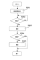
図3は、本実施形態の音声処理動作の流れを示すフローチャートである。録音を行う場合、まず録音する音声の録音時間を設定する(ステップS301)。この録音時間は記録メディアの空き容量によって変化することはなく、RAM上の領域を利用するため対象となる音によって定められた固定値である。後述するように、録音する音声の用途として起動音、操作音、シャッター音、セルフタイマー音が設定され、それぞれの録音時間が予め設定されており、所望の用途を選択することにより録音時間を設定する。
【0051】
録音時間を設定した後、ユーザは任意のタイミングで録音を開始する(ステップS302)。
【0052】
録音開始がユーザの意思によって始められると、上記ステップS301にて設定された時間だけ音声を録音する(ステップS303)。その間、録音停止等の他の操作はできないようにし、設定された録音時間が経過するまで録音を実行する。
【0053】
その後、録音された音声を登録するかどうかユーザが判断し(ステップS304)、登録する場合は、デジタルカメラ内の効果音の一つとして登録する(ステップS305)。
【0054】
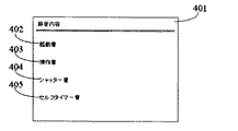
図4は、音声を登録する場合の液晶画面401(図2でいう液晶画面312)の表示例を示す。音声を登録する項目(音声の用途)として、起動音402、操作音403、シャッター音404、セルフタイマー音405が設定されている。これら項目から上ボタン307と下ボタン308で項目を移動し、登録したい項目まで移動させた後、決定ボタン303で録音画面に移行する。
【0055】
図5は、起動音を録音する場合の液晶画面501(図2でいう液晶画面312)の表示例を示す。画面の下部に示すパネルには、録音ボタン502と、登録ボタン503と、録音時間が表示されるカウンタ504が表示される。左ボタン305と右ボタン306でボタンのフォーカスを移動し、決定ボタン303で実行する。録音前には登録ボタンは選択できなくなっている。
【0056】
図6は、操作音を録音する場合の液晶画面601(図2でいう液晶画面312)の表示例を示す。操作音の場合、図5で説明した起動音の場合等に比べて録音時間が0.3秒と短く設定されており、その録音時間がカウンタ602に表示されている。
【0057】
なお、図5、6に示した録音時の画面において、録音開始と登録の機能のみを持たせるようにした例を説明したが、この画面上で音声の再生やボリュームの調整等の機能を持たせるようにしてもよい。その場合、再生して録音内容を確認し、登録するかどうかを判断することが可能となる。
【0058】
(その他の実施の形態)
上述した実施形態の機能を実現するべく各種のデバイスを動作させるように、該各種デバイスと接続された装置或いはシステム内のコンピュータに対し、上記実施形態の機能を実現するためのソフトウェアのプログラムコードを供給し、そのシステム或いは装置のコンピュータ(CPU或いはMPU)に格納されたプログラムに従って上記各種デバイスを動作させることによって実施したものも、本発明の範疇に含まれる。
【0059】
また、この場合、上記ソフトウェアのプログラムコード自体が上述した実施形態の機能を実現することになり、そのプログラムコード自体は本発明を構成する。そのプログラムコードの伝送媒体としては、プログラム情報を搬送波として伝搬させて供給するためのコンピュータネットワーク(LAN、インターネット等のWAN、無線通信ネットワーク等)システムにおける通信媒体(光ファイバ等の有線回線や無線回線等)を用いることができる。
【0060】
さらに、上記プログラムコードをコンピュータに供給するための手段、例えばかかるプログラムコードを格納した記録媒体は本発明を構成する。かかるプログラムコードを記憶する記録媒体としては、例えばフレキシブルディスク、ハードディスク、光ディスク、光磁気ディスク、CD−ROM、磁気テープ、不揮発性のメモリカード、ROM等を用いることができる。
【0061】
また、コンピュータが供給されたプログラムコードを実行することにより、上述の実施形態の機能が実現されるだけでなく、そのプログラムコードがコンピュータにおいて稼働しているOS(オペレーティングシステム)或いは他のアプリケーションソフト等と共同して上述の実施形態の機能が実現される場合にもかかるプログラムコードは本発明の実施形態に含まれることはいうまでもない。
【0062】
さらに、供給されたプログラムコードがコンピュータの機能拡張ボードやコンピュータに接続された機能拡張ユニットに備わるメモリに格納された後、そのプログラムコードの指示に基づいてその機能拡張ボードや機能拡張ユニットに備わるCPU等が実際の処理の一部又は全部を行い、その処理によって上述した実施形態の機能が実現される場合にも本発明に含まれることはいうまでもない。
【0063】
なお、上記実施形態において示した各部の形状及び構造は、何れも本発明を実施するにあたっての具体化のほんの一例を示したものに過ぎず、これらによって本発明の技術的範囲が限定的に解釈されてはならないものである。すなわち、本発明はその精神、又はその主要な特徴から逸脱することなく、様々な形で実施することができる。例えば、記録媒体200及び210は、PCMCIAカードやコンパクトフラッシュ(R)等のメモリカード、ハードディスク等だけでなく、マイクロDAT、光磁気ディスク、CD−RやCD−WR等の光ディスク、DVD等の相変化型光ディスク等で構成されていても勿論問題無い。また、記録媒体200及び210がメモリカードとハードディスク等が一体となった複合媒体であっても勿論問題無い。さらに、その複合媒体から一部が着脱可能な構成としても勿論問題無い。また、記録媒体200及び210は撮像装置100と分離していて任意に接続可能なものとして説明したが、いずれか或いは全ての記録媒体が撮像装置100に固定したままとなっていても勿論問題無い。
【0064】
【発明の効果】
以上述べたように本発明によれば、録音開始後は、設定された録音時間が経過するまで録音を実行するようにし、停止操作等を行うことができなくすることにより、極端に短い時間の録音、例えばデジタルカメラ等の撮像装置の操作音や起動音として音声を録音するような場合でも、簡単な操作で録音することができる。
【図面の簡単な説明】
【図1】本実施形態の音声処理装置を含むデジタルカメラ等の撮像装置100の構成を示す図である。
【図2】撮像装置100の操作部材を説明するための図である。
【図3】音声処理動作の流れを示すフローチャートである。
【図4】音声を登録する場合の画面表示の一例を示す図である。
【図5】起動音を録音する場合の画面表示の一例を示す図である。
【図6】操作音を録音する場合の画面表示の一例を示す図である。
【符号の説明】
14 撮像素子
24 画像表示メモリ
28 画像表示部
30 メモリ
50 システム制御回路
54 表示部
72 マイク
74 スピーカ
200 記録媒体
201 記録媒体[0001]
TECHNICAL FIELD OF THE INVENTION
The present invention relates to an audio processing device, a method, a computer program, and a computer-readable storage medium used for an imaging device that captures, records, and reproduces a moving image.
[0002]
[Prior art]
2. Description of the Related Art Conventionally, electronic cameras for recording and reproducing still images and moving images using a memory card having a solid-state memory element as a recording medium have already been marketed, and electronic cameras provided with an electronic finder such as a color liquid crystal panel have also been sold. According to these electronic cameras, it is possible for the user of the electronic camera to determine the composition by continuously displaying images before photographing and to reproduce and confirm the photographed images. In particular, the function of reproducing a photographed image immediately after photographing is highly convenient and is a useful function for the user of the electronic camera.
[0003]
In digital cameras, more and more products have a function of capturing not only a still image but also a moving image, and the recording time and image size of the moving image have been improved. Some of such digital cameras are equipped with a microphone and a speaker, and have a function of recording and reproducing voice using the microphone and the speaker, and some have a function such as a post-recording and a voice memo.
[0004]
On the other hand, there have been models that emit not only electronic sounds but also various sound effects from speakers as start-up sounds and operation sounds of digital cameras. In these models, when the shutter is pressed by the self-timer, it is possible to shoot using sound effects such as "Yes, cheese" and "Pash".
[0005]
[Problems to be solved by the invention]
Using the functions of the microphone and the speaker of the digital camera, the recorded sound can be used as the operation sound and the start-up sound of the digital camera. However, in this case, there is a problem that it is difficult to record well because the reproduction time is extremely short. It is conceivable to cut out and use the voice recorded by post-recording or the like, but in that case, the operation becomes complicated and the function becomes difficult for the user to understand.
[0006]
The present invention has been made in view of the above problems, and has as its object to enable recording with a simple operation, for example, when recording a sound as an operation sound or a startup sound of an imaging device such as a digital camera.
[0007]
[Means for Solving the Problems]
The voice processing device of the present invention includes a recording time setting unit that sets a recording time, a recording start receiving unit that receives a recording start instruction, and a recording start instruction that receives a recording start instruction until the set recording time elapses. And a recording means for performing the following.
[0008]
Another feature of the audio processing device of the present invention is that the audio processing device includes a reproducing unit that reproduces the recorded audio.
[0009]
Another feature of the audio processing device of the present invention is that the recording time is preset according to a plurality of uses of the sound to be recorded, and the recording time is set by selecting a desired use. Is to do.
[0010]
Another feature of the audio processing device of the present invention is that a captured moving image is recorded on a recording medium, can be reproduced and displayed, and is provided in an imaging device including a microphone and a speaker. It is in.
[0011]
Another feature of the sound processing apparatus of the present invention is that a plurality of sets including at least one of a start-up sound, an operation sound, a shutter sound, and a self-timer sound are set as uses of the sound to be recorded. The time is set in advance, and the point is that the recording time is set by selecting a desired use.
[0012]
Another feature of the audio processing device of the present invention is that a recording time set in advance according to a use of the audio is displayed on a display unit of the imaging device.
[0013]
The sound processing method of the present invention includes a recording time setting procedure for setting a recording time, a recording start receiving procedure for receiving a recording start instruction, and a recording start instruction for receiving a recording start instruction, until the set recording time elapses. And a recording procedure for performing the following.
[0014]
The computer program according to the present invention is configured such that a recording time setting process for setting a recording time, a recording start receiving process for receiving a recording start instruction, and a recording start instruction for receiving a recording start instruction until the set recording time elapses. It is characterized in that a recording process to be executed is executed by a computer.
[0015]
The computer-readable storage medium of the present invention is characterized in that the computer program of the present invention is stored.
[0016]
BEST MODE FOR CARRYING OUT THE INVENTION
Hereinafter, embodiments of a speech processing apparatus, a method, a computer program, and a computer-readable storage medium of the present invention will be described with reference to the drawings.
[0017]
FIG. 1 is a diagram illustrating a configuration of an
[0018]
Reference numeral 18 denotes a timing generation circuit that supplies a clock signal and a control signal to the image sensor 14, the A /
[0019]
[0020]
A
[0021]
[0022]
[0023]
A compression / decompression circuit 32 compresses and decompresses image data by adaptive discrete cosine transform (ADCT) or the like. The compression / decompression circuit 32 reads an image stored in the
[0024]
An exposure control unit 40 controls the
[0025]
Reference numeral 48 denotes a flash, which also has a function of projecting AF auxiliary light and a function of flash light control. The exposure control unit 40 and the distance measurement control unit 42 are controlled using the TTL method. The
[0026]
50 is a system control circuit for controlling the whole. In the present embodiment, the
[0027]
Reference numeral 54 denotes a display unit such as a liquid crystal display device or a speaker that displays an operation state or a message using characters, images, sounds, or the like in accordance with the execution of a program in the
[0028]
Of the display contents of the display unit 54, those displayed on the LCD or the like include a single shot / continuous shooting display, a self-timer display, a compression ratio display, a recording pixel number display, a recording number display, a remaining number of images displayable, a shutter. Speed display, Aperture display, Exposure compensation display, Flash display, Red-eye reduction display, Macro shooting display, Buzzer setting display, Battery remaining battery display, Battery remaining display, Error display, Information display with multiple digits, Recording The display includes the attachment / detachment state display of the
[0029]
Among the display contents of the display unit 54, those displayed in the
[0030]
Reference numeral 56 denotes an electrically erasable / recordable nonvolatile memory, for example, an EEPROM or the like.
[0031]
[0032]
Here, these operation units will be specifically described.
[0033]
[0034]
Reference numeral 64 denotes a shutter switch SW2 which is turned on when the operation of a shutter button (not shown) is completed, and writes a signal read from the
[0035]
An image display ON / OFF switch 66 can set ON / OFF of the image display unit 28. With this function, it is possible to save power by cutting off the current supply to an image display unit such as a TFT LCD when taking a picture using the
[0036]
Reference numeral 68 denotes a quick review ON / OFF switch, which sets a quick review function for automatically playing back image data shot immediately after shooting. In this embodiment, a function for setting a quick review function when the image display unit 28 is turned off is provided.
[0037]
Reference numeral 70 denotes an operation unit including various buttons, a touch panel, and the like. A menu button, a set button, a macro button, a multi-screen playback page break button, a flash setting button, a single / continuous / self-timer switching button, and a menu shift + (plus) Buttons, a menu move- (minus) button, a play image move + (plus) button, a play image- (minus) button, a photographing image quality selection button, an exposure correction button, a date / time setting button, and the like.
[0038]
72 is a microphone, and 74 is a speaker. Reference numeral 80 denotes a power control unit, which includes a battery detection circuit, a DC-DC converter, a switch circuit for switching a block to be energized, and the like. The DC-DC converter is controlled based on an instruction from the
[0039]
Reference numeral 82 denotes a connector, 84 denotes a connector, and 86 denotes a power supply unit including a primary battery such as an alkaline battery or a lithium battery, a secondary battery such as a NiCd battery, a NiMH battery, or a Li battery, and an AC adapter.
[0040]
Reference numerals 90 and 94 denote an interface with a recording medium such as a memory card or a hard disk, reference numerals 92 and 96 denote connectors for connecting to a recording medium such as a memory card or a hard disk, and reference numeral 98 denotes a connector 92 or 96 to which a
[0041]
[0042]
[0043]
A communication unit 110 has various communication functions such as RS232C, USB, IEEE1394, P1284, SCSI, modem, LAN, and wireless communication.
[0044]
Reference numeral 112 denotes a connector connected to another device by the communication unit 110 or an antenna in the case of wireless communication.
[0045]
[0046]
210 is a recording medium such as a memory card or a hard disk. The recording medium 210 includes a
[0047]
FIG. 2 is a diagram for explaining operation members of the
[0048]
A
[0049]
A
[0050]
FIG. 3 is a flowchart showing the flow of the voice processing operation of the present embodiment. When recording, first, the recording time of the voice to be recorded is set (step S301). This recording time does not change depending on the free space of the recording medium, and is a fixed value determined by a target sound in order to use an area on the RAM. As will be described later, start-up sound, operation sound, shutter sound, and self-timer sound are set as the use of the sound to be recorded, and the respective recording times are preset, and the recording time is set by selecting a desired use. I do.
[0051]
After setting the recording time, the user starts recording at an arbitrary timing (step S302).
[0052]
When the start of recording is started by the user's intention, a voice is recorded for the time set in step S301 (step S303). During that time, other operations such as stopping recording are disabled, and recording is performed until the set recording time has elapsed.
[0053]
Thereafter, the user determines whether or not to register the recorded voice (step S304), and if so, registers as one of the sound effects in the digital camera (step S305).
[0054]
FIG. 4 shows a display example of the liquid crystal screen 401 (the
[0055]
FIG. 5 shows a display example of the liquid crystal screen 501 (the
[0056]
FIG. 6 shows a display example of the liquid crystal screen 601 (the
[0057]
Although the example in which only the recording start and registration functions are provided on the recording screens shown in FIGS. 5 and 6 has been described, functions such as sound reproduction and volume adjustment are provided on this screen. You may make it do. In that case, it is possible to play back and confirm the recorded contents and determine whether or not to register.
[0058]
(Other embodiments)
In order to operate various devices to realize the functions of the above-described embodiments, program codes of software for realizing the functions of the above-described embodiments are transmitted to an apparatus connected to the various devices or a computer in a system. The present invention also includes those which are supplied and operated by operating the above-described various devices according to a program stored in a computer (CPU or MPU) of the system or the apparatus.
[0059]
In this case, the software program code itself implements the functions of the above-described embodiment, and the program code itself constitutes the present invention. As a transmission medium of the program code, a communication medium (a wired line or a wireless line such as an optical fiber) in a computer network (WAN such as a LAN or the Internet, a wireless communication network, etc.) system for transmitting and supplying the program information as a carrier wave. Etc.) can be used.
[0060]
Further, means for supplying the program code to a computer, for example, a recording medium storing the program code constitutes the present invention. As a recording medium for storing such a program code, for example, a flexible disk, a hard disk, an optical disk, a magneto-optical disk, a CD-ROM, a magnetic tape, a nonvolatile memory card, a ROM, and the like can be used.
[0061]
When the computer executes the supplied program code, not only the functions of the above-described embodiments are realized, but also the OS (operating system) or other application software running on the computer. Needless to say, such a program code is also included in the embodiment of the present invention when the functions of the above-described embodiment are implemented in cooperation with the above.
[0062]
Further, after the supplied program code is stored in a memory provided in a function expansion board of a computer or a function expansion unit connected to the computer, a CPU provided in the function expansion board or the function expansion unit based on the instruction of the program code. It goes without saying that the present invention also includes a case where the functions of the above-described embodiments are implemented by performing part or all of the actual processing.
[0063]
It should be noted that the shapes and structures of the respective parts shown in the above embodiments are merely examples of the embodiment for carrying out the present invention, and the technical scope of the present invention is interpreted in a limited manner. It must not be done. That is, the present invention can be embodied in various forms without departing from the spirit or main features thereof. For example, the
[0064]
【The invention's effect】
As described above, according to the present invention, after the recording is started, the recording is executed until the set recording time elapses, and the stop operation or the like cannot be performed. Even when recording, for example, recording a sound as an operation sound or a start-up sound of an imaging device such as a digital camera, the recording can be performed by a simple operation.
[Brief description of the drawings]
FIG. 1 is a diagram illustrating a configuration of an
FIG. 2 is a diagram for explaining operation members of the
FIG. 3 is a flowchart showing a flow of an audio processing operation.
FIG. 4 is a diagram showing an example of a screen display when a voice is registered.
FIG. 5 is a diagram showing an example of a screen display when a start-up sound is recorded.
FIG. 6 is a diagram showing an example of a screen display when an operation sound is recorded.
[Explanation of symbols]
14
Claims (9)
録音の開始指示を受け付ける録音開始受付手段と、
録音の開始指示を受け付けると、前記設定された録音時間が経過するまで録音を実行する録音手段とを備えたことを特徴とする音声処理装置。Recording time setting means for setting the recording time;
Recording start receiving means for receiving a recording start instruction;
A sound processing device comprising: a recording unit that, when receiving a recording start instruction, performs recording until the set recording time elapses.
録音の開始指示を受け付ける録音開始受付手順と、
録音の開始指示を受け付けると、前記設定された録音時間が経過するまで録音を実行する録音手順とを有することを特徴とする音声処理方法。Recording time setting procedure to set the recording time,
A recording start reception procedure for receiving a recording start instruction,
A recording procedure for receiving the instruction to start recording and performing recording until the set recording time has elapsed.
録音の開始指示を受け付ける録音開始受付処理と、
録音の開始指示を受け付けると、前記設定された録音時間が経過するまで録音を実行する録音処理とをコンピュータに実行させることを特徴とするコンピュータプログラム。A recording time setting process for setting a recording time;
A recording start reception process for receiving a recording start instruction;
A computer program which, upon receipt of a recording start instruction, causes a computer to execute a recording process for performing recording until the set recording time has elapsed.
Priority Applications (3)
| Application Number | Priority Date | Filing Date | Title |
|---|---|---|---|
| JP2002251709A JP2004096227A (en) | 2002-08-29 | 2002-08-29 | Sound processing apparatus and method therefor, computer program, and computer readable storage medium |
| CNB031560148A CN1251475C (en) | 2002-08-29 | 2003-08-28 | Acoustic processor, processing method, computer program and storage media |
| US10/651,735 US7778429B2 (en) | 2002-08-29 | 2003-08-29 | Audio processor, audio processing method, computer program, and computer readable storage medium |
Applications Claiming Priority (1)
| Application Number | Priority Date | Filing Date | Title |
|---|---|---|---|
| JP2002251709A JP2004096227A (en) | 2002-08-29 | 2002-08-29 | Sound processing apparatus and method therefor, computer program, and computer readable storage medium |
Related Child Applications (1)
| Application Number | Title | Priority Date | Filing Date |
|---|---|---|---|
| JP2009099143A Division JP4857358B2 (en) | 2009-04-15 | 2009-04-15 | Sound processing apparatus, imaging apparatus, sound processing method, computer program, and computer-readable storage medium |
Publications (2)
| Publication Number | Publication Date |
|---|---|
| JP2004096227A true JP2004096227A (en) | 2004-03-25 |
| JP2004096227A5 JP2004096227A5 (en) | 2005-11-04 |
Family
ID=31972696
Family Applications (1)
| Application Number | Title | Priority Date | Filing Date |
|---|---|---|---|
| JP2002251709A Pending JP2004096227A (en) | 2002-08-29 | 2002-08-29 | Sound processing apparatus and method therefor, computer program, and computer readable storage medium |
Country Status (3)
| Country | Link |
|---|---|
| US (1) | US7778429B2 (en) |
| JP (1) | JP2004096227A (en) |
| CN (1) | CN1251475C (en) |
Families Citing this family (7)
| Publication number | Priority date | Publication date | Assignee | Title |
|---|---|---|---|---|
| US7924324B2 (en) * | 2003-11-05 | 2011-04-12 | Sanyo Electric Co., Ltd. | Sound-controlled electronic apparatus |
| FR2908901B1 (en) * | 2006-11-22 | 2009-03-06 | Thomson Licensing Sas | METHOD FOR ASSOCIATING A FIXED IMAGE ASSOCIATED WITH A SOUND SEQUENCE, AND APPARATUS FOR MAKING SUCH A ASSOCIATION |
| JP5040734B2 (en) * | 2008-03-05 | 2012-10-03 | ソニー株式会社 | Image processing apparatus, image recording method, and program |
| JP5538918B2 (en) * | 2010-01-19 | 2014-07-02 | キヤノン株式会社 | Audio signal processing apparatus and audio signal processing system |
| JP5821257B2 (en) * | 2011-04-18 | 2015-11-24 | ソニー株式会社 | IMAGING DEVICE, IMAGING DEVICE CONTROL METHOD, AND PROGRAM |
| JP2015122726A (en) * | 2013-11-25 | 2015-07-02 | 株式会社リコー | Image processing apparatus, image processing method, and image processing program |
| JP7192477B2 (en) * | 2018-12-18 | 2022-12-20 | コニカミノルタ株式会社 | IMAGE FORMING APPARATUS, IMAGE FORMING APPARATUS CONTROL METHOD AND PROGRAM |
Family Cites Families (20)
| Publication number | Priority date | Publication date | Assignee | Title |
|---|---|---|---|---|
| JPS61277280A (en) * | 1985-05-31 | 1986-12-08 | Sony Corp | Electronic still camera |
| US5214516A (en) * | 1985-09-20 | 1993-05-25 | Canon Kabushiki Kaisha | Image pickup system with an indication of the audio signal recording state |
| JPH0351537U (en) | 1989-09-22 | 1991-05-20 | ||
| JP3276110B2 (en) | 1989-11-20 | 2002-04-22 | オリンパス光学工業株式会社 | camera |
| US5489955A (en) * | 1992-07-28 | 1996-02-06 | Olympus Optical Co., Ltd. | Camera having sound recording function |
| JP2584412Y2 (en) * | 1993-09-07 | 1998-11-05 | ニチメン株式会社 | Grip for film type simple camera with lens |
| DE19619519A1 (en) * | 1995-05-25 | 1996-11-28 | Eastman Kodak Co | Sound-recording camera |
| US6263147B1 (en) * | 1996-02-28 | 2001-07-17 | Sun Microsystems, Inc. | Delayed decision recording device |
| GB2312050B (en) * | 1996-04-10 | 2001-04-04 | Eastman Kodak Co | Camera with smile sound |
| JP4397054B2 (en) * | 1996-06-13 | 2010-01-13 | 株式会社ニコン | Information input device |
| JPH104530A (en) * | 1996-06-14 | 1998-01-06 | Nikon Corp | Information recorder |
| JP4040125B2 (en) * | 1996-09-18 | 2008-01-30 | ソニー株式会社 | Audio signal recording device |
| WO1998015955A1 (en) * | 1996-10-09 | 1998-04-16 | Sony Corporation | Recorder using information signal recording medium |
| US6353809B2 (en) * | 1997-06-06 | 2002-03-05 | Olympus Optical, Ltd. | Speech recognition with text generation from portions of voice data preselected by manual-input commands |
| JP3899622B2 (en) | 1997-11-20 | 2007-03-28 | カシオ計算機株式会社 | Camera apparatus and imaging method |
| US6779196B1 (en) * | 1998-06-22 | 2004-08-17 | Phillip Igbinadolor | Integrated car dubbing system |
| CN1269659A (en) | 1999-04-05 | 2000-10-11 | 英业达集团(上海)电子技术有限公司 | Coming call promoting device and method for mobile phone set |
| JP2001142131A (en) | 1999-11-15 | 2001-05-25 | Olympus Optical Co Ltd | Camera |
| US20030081934A1 (en) * | 2001-10-30 | 2003-05-01 | Kirmuss Charles Bruno | Mobile video recorder control and interface |
| US7535496B2 (en) * | 2002-01-30 | 2009-05-19 | Intel Corporation | Audio-based attention grabber for imaging devices |
-
2002
- 2002-08-29 JP JP2002251709A patent/JP2004096227A/en active Pending
-
2003
- 2003-08-28 CN CNB031560148A patent/CN1251475C/en not_active Expired - Fee Related
- 2003-08-29 US US10/651,735 patent/US7778429B2/en not_active Expired - Fee Related
Also Published As
| Publication number | Publication date |
|---|---|
| US7778429B2 (en) | 2010-08-17 |
| US20040044428A1 (en) | 2004-03-04 |
| CN1251475C (en) | 2006-04-12 |
| CN1491026A (en) | 2004-04-21 |
Similar Documents
| Publication | Publication Date | Title |
|---|---|---|
| JP4095383B2 (en) | Imaging apparatus, control method therefor, and storage medium | |
| JP2004096641A (en) | Imaging apparatus and its control method | |
| JP2007028070A (en) | Device and method for preserving picture, and control program | |
| JP2004096227A (en) | Sound processing apparatus and method therefor, computer program, and computer readable storage medium | |
| JP5836578B2 (en) | IMAGING DEVICE, IMAGING DEVICE CONTROL METHOD, AND PROGRAM | |
| JP2005221771A (en) | Imaging device and function display method | |
| JP4810485B2 (en) | Image processing apparatus, image processing method, and computer program | |
| JP2006203689A (en) | Imaging apparatus and control method thereof, program, and storage medium | |
| JP2002094871A (en) | Imaging equipment, control method of imaging equipment, and storage medium capable of computer reading | |
| JP2001326849A (en) | Image pickup device, control method for the image pickup device, and medium for providing control program of the image pickup device | |
| JP4560189B2 (en) | Imaging device | |
| JP2006042028A (en) | Image processor, and control method, control program and storage medium for image processor | |
| JP4217411B2 (en) | Image processing apparatus, image processing method, recording medium, and program | |
| JP6006567B2 (en) | Movie playback apparatus and movie playback method | |
| JP4857358B2 (en) | Sound processing apparatus, imaging apparatus, sound processing method, computer program, and computer-readable storage medium | |
| JP2003244654A (en) | Image processing apparatus, image processing method, and storage medium | |
| JP2007251414A (en) | Image photographing unit, control method therefor, and control program | |
| JP2002314872A (en) | Imaging device and imaging method | |
| JP2006203665A (en) | Imaging device and method therefor, and recording medium and program | |
| JP2005110128A (en) | Imaging apparatus and imaging control method | |
| JP2004096226A (en) | Image processing apparatus and method therefor, computer program, and computer readable storage medium | |
| JP2003046850A (en) | Image-processing apparatus and method, record medium, and program | |
| JP3854795B2 (en) | Image processing apparatus, image processing apparatus control method, and storage medium storing computer-readable program | |
| JP2001324750A (en) | Image pickup device and control method therefor | |
| JP5361973B2 (en) | IMAGING DEVICE, ITS CONTROL METHOD, PROGRAM, AND STORAGE MEDIUM |
Legal Events
| Date | Code | Title | Description |
|---|---|---|---|
| A521 | Request for written amendment filed |
Free format text: JAPANESE INTERMEDIATE CODE: A523 Effective date: 20050811 |
|
| A621 | Written request for application examination |
Free format text: JAPANESE INTERMEDIATE CODE: A621 Effective date: 20050811 |
|
| A977 | Report on retrieval |
Free format text: JAPANESE INTERMEDIATE CODE: A971007 Effective date: 20080227 |
|
| A131 | Notification of reasons for refusal |
Free format text: JAPANESE INTERMEDIATE CODE: A131 Effective date: 20080304 |
|
| A521 | Request for written amendment filed |
Free format text: JAPANESE INTERMEDIATE CODE: A523 Effective date: 20080430 |
|
| A02 | Decision of refusal |
Free format text: JAPANESE INTERMEDIATE CODE: A02 Effective date: 20090217 |
|
| A521 | Request for written amendment filed |
Free format text: JAPANESE INTERMEDIATE CODE: A523 Effective date: 20090415 |
|
| A911 | Transfer to examiner for re-examination before appeal (zenchi) |
Free format text: JAPANESE INTERMEDIATE CODE: A911 Effective date: 20090427 |
|
| A912 | Re-examination (zenchi) completed and case transferred to appeal board |
Free format text: JAPANESE INTERMEDIATE CODE: A912 Effective date: 20090522 |