JP2004085664A - Drawing system - Google Patents
Drawing system Download PDFInfo
- Publication number
- JP2004085664A JP2004085664A JP2002243275A JP2002243275A JP2004085664A JP 2004085664 A JP2004085664 A JP 2004085664A JP 2002243275 A JP2002243275 A JP 2002243275A JP 2002243275 A JP2002243275 A JP 2002243275A JP 2004085664 A JP2004085664 A JP 2004085664A
- Authority
- JP
- Japan
- Prior art keywords
- focus camera
- reference hole
- relative position
- fixed
- magnification
- Prior art date
- Legal status (The legal status is an assumption and is not a legal conclusion. Google has not performed a legal analysis and makes no representation as to the accuracy of the status listed.)
- Pending
Links
Images


Abstract
Description
【0001】
【発明の属する技術分野】
本発明は、レーザビームにより被描画体に回路パターンを直接描画するレーザ描画装置およびこのレーザ描画装置を用いる描画システムに関するものである。
【0002】
【従来の技術】
上述したようなレーザ描画装置は、例えばオートメーション化されたプリント回路基板の製造工程において、基板の表面に微細な回路パターンを形成する描画システムに使用され、従来例として特開平10−162145号公報が挙げられる。描画システムでは、感光性の被描画体、例えば表面にフォトレジスト層が設けられた基板がレーザ描画装置に搬送され、このレーザ描画装置においてフォトレジスト層が露光される、具体的にはCAD/CAMシステムにより設計/編集された回路パターンのラスタデータに従ってレーザビームが変調され、ラスター走査によってフォトレジスト層の回路パターン部分だけが光硬化させられることにより、回路パターンがフォトレジスト層に直接描画される。描画後、レーザ描画装置から排出された基板上の未硬化のフォトレジストが溶剤によって洗い流され、銅等を腐食させる薬剤で処理されると、フォトレジストが付着したままの部位が腐食されずに残り、設計された回路パターンと同一の回路パターンが基板上に形成されることになる。
【0003】
ところで、上記レーザ描画装置においては、基板を描画テーブル上に載置し、描画テーブル上の基板に対してレーザビームを主走査方向に偏向させつつ描画テーブル即ち基板を副走査方向に相対移動させることにより描画を行っている。レーザ描画装置は同一規格の複数の基板に対して回路パターンを常に同じ位置で描画することが求められるので、従来では、基板に形成した所定穴径の基準穴の描画テーブルに対する相対位置をCCDカメラ等を用いて計測し、得られた相対位置データに基づいて描画開始位置を制御することにより、各基板と回路パターンとを整合させている。CCDカメラは基板に対して一定の距離だけ離れた位置に設置され、その焦点距離は固定される。
【0004】
近年では、回路パターンの高精密化及び高密度化に伴ってレーザ描画装置に要求される描画精度はミクロンオーダになり、基準穴の計測精度を高めることが求められている。この課題を解決する方法として、例えばCCDカメラの倍率を上げることが考えられるが、この場合CCDカメラの視野が狭くなるため、基準穴が視野から外れて計測不能となるという現象が生じ易くなる。これは、各基板の外形寸法誤差や基準穴の穴加工誤差あるいは基板の搬送位置ずれ等といった様々な要因により、描画テーブルに対する基準穴の位置が個々の基板で異なることがあるからである。基準穴が計測できなかった基板に対しては、再度計測を行うか、あるいは不良品として破棄するかしかなく作業効率が低下する原因となっていた。
【0005】
【発明が解決しようとする課題】
本発明は上記問題点に鑑みて成されたものであり、確実かつ高精度に回路パターンを描画するとともに作業効率を向上させることが課題である。
【0006】
【課題を解決するための手段】
本発明の描画装置は、テーブルに載置された感光性の被描画体を、走査光学系から出射したレーザビームにより主走査方向に走査すると共に、テーブルを副走査方向に相対移動させることによって被描画体の表面に回路パターンを描画するレーザ描画装置と、テーブルに被描画体を搬送する搬送装置と、被描画体のテーブルへの搬送時に生じる位置ずれと、被描画体の外形寸法誤差と、被描画体に形成された基準穴の加工誤差とを解消して、被描画体に対して回路パターンを整合させる整合手段を備えることを最も主要な特徴とする。
【0007】
上記露光システムの整合手段は、例えばレーザ描画装置に設けられ基準穴を撮像する可変焦点カメラと、可変焦点カメラにより得られる画像に基づいてテーブルに対する基準穴の相対位置データを求める画像処理手段と、相対位置データに基づいてテーブルの描画開始位置およびレーザビームの走査開始位置を調整する調整手段とを備えてもよく、好ましくは可変焦点カメラを第1の倍率に設定して撮像したときに得られる映像に基づいて基準穴を検出し、テーブルおよび可変焦点カメラを相対移動させて基準穴を可変焦点カメラの視野の中央に位置決めし、さらに可変焦点カメラを第1の倍率より高い第2の倍率に設定して撮像したときに得られる映像に基づいて相対位置データを求める。
【0008】
上記露光システムの整合手段は、例えばレーザ描画装置に設けられ基準穴を第1の倍率で撮像する第1の固定焦点カメラと、レーザ描画装置に設けられ基準穴を第1の倍率より高い第2の倍率で撮像する第2の固定焦点カメラと、第2の固定焦点カメラにより得られる画像に基づいてテーブルに対する基準穴の相対位置データを求める画像処理手段と、相対位置データに基づいてテーブルの描画開始位置およびレーザビームの走査開始位置を調整する調整手段とを備えてもよく、好ましくは第1の固定焦点カメラが撮像した映像に基づいて基準穴を検出し、テーブルおよび第2の固定焦点カメラを相対移動させて基準穴を第2の固定焦点カメラの視野の中央に位置決めし、さらに第2の固定焦点カメラが撮像した映像に基づいて相対位置データを求める。
【0009】
上記露光システムの整合手段は、例えばテーブルに対する被描画体の外周縁の相対位置を検出するセンサと、レーザ描画装置に設けられ基準穴を所定の倍率で撮像する固定焦点カメラと、固定焦点カメラにより得られる画像に基づいてテーブルに対する基準穴の相対位置データを求める画像処理手段と、センサの検出結果と相対位置データとに基づいてテーブルの描画開始位置およびレーザビームの走査開始位置を調整する調整手段とを備えていてもよい。
【0010】
上記露光システムの整合手段は、例えばテーブルに設けられ被描画体の一側面に当接する固定部材と、被描画体を固定部材に向かって付勢する付勢部材と、レーザ描画装置に設けられ基準穴を所定の倍率で撮像する固定焦点カメラと、固定焦点カメラにより得られる画像に基づいてテーブルに対する基準穴の相対位置データを求める画像処理手段と、相対位置データに基づいてテーブルの描画開始位置およびレーザビームの走査開始位置を調整する調整手段とを備えてもよく、好ましくは固定部材および付勢部材との協働によってテーブルに被描画体を位置決めした後に、に固定焦点カメラが撮像した映像に基づいて相対位置データを求める。
【0011】
上記露光システムの整合手段は、例えば搬送装置に設けられ基準穴を第1の倍率で撮像する第1の固定焦点カメラと、レーザ描画装置に設けられ基準穴を第1の倍率より高い第2の倍率で撮像する第2の固定焦点カメラと、第2の固定焦点カメラにより得られる画像に基づいてテーブルに対する基準穴の相対位置データを求める画像処理手段と、相対位置データに基づいてテーブルの描画開始位置およびレーザビームの走査開始位置を調整する調整手段とを備えてもよく、好ましくは搬送装置において第1の固定焦点カメラが撮像した映像に基づいて基準穴を検出し、搬送装置からレーザ描画装置に被描画体を搬送すると共に、基準穴の検出結果に基づいてテーブルおよび第2の固定焦点カメラを相対移動させて基準穴を第2の固定焦点カメラの視野の中央に位置決めし、さらに第2の固定焦点カメラが撮像した映像に基づいて相対位置データを求める。
【0012】
上記露光システムの整合手段は、例えば搬送装置に設けられ基準穴を撮像する可変焦点カメラと、可変焦点カメラにより得られる画像に基づいてテーブルに対する基準穴の相対位置データを求める画像処理手段と、相対位置データに基づいてテーブルの描画開始位置およびレーザビームの走査開始位置を調整する調整手段とを備えてもよく、好ましくは搬送装置において、可変焦点カメラを第1の倍率に設定して撮像したときに得られる映像に基づいて基準穴を検出し、可変焦点カメラを相対移動させて基準穴を可変焦点カメラの視野の中央に位置決めし、さらに可変焦点カメラを第1の倍率より高い第2の倍率に設定して撮像したときに得られる映像に基づいて相対位置データを求めた後、相対位置データをレーザ描画装置に与える。
【0013】
【発明の実施の形態】
以下、本発明の実施形態について添付図面を参照して説明する。
【0014】
図1は本発明の第1実施形態を示す図であって、描画システムを簡略化して示す図である。
描画システムは、レーザビームによって回路パターンを感光性の被描画体である基板Sに直接描画するレーザ描画装置10と、このレーザ描画装置10に基板Sを搬入する、またはレーザ描画装置10から排出された基板Sを次の処理装置(図示せず)に送り出す搬送装置とを備えている。搬送装置は例えばベルトコンベアであり、図1ではその一部である搬入用ベルト22および送出用ベルト24のみを示す。基板Sは長方形の板状を呈し、その上面にはフォトレジスト層が設けられている。
【0015】
レーザ描画装置10は、所定位置に固定された光学ユニット12と、基板Sが水平に載置される描画テーブル14とを備える。光学ユニット12は図示しないレーザ光源と光学系とを備え、描画テーブル14上の基板Sに向かってレーザビームを主走査方向に沿って出射する。描画テーブル14即ち基板Sに対する主走査方向の走査開始位置は任意に変更可能である。描画テーブル14は搬入用ベルト22と送出用ベルト24との間に位置する準備位置(実線で示す)と、光学ユニット12の略鉛直下方に位置する描画開始位置(破線で示す)との間で、副走査方向に沿って相対移動自在である。
【0016】
描画テーブル14の移動平面上にはレーザ描画装置の機枠に対して不動となったXY2次元直交座標系が設定され、この座標系のX軸は副走査方向に延び、またY軸は主走査方向に延びる。XY2次元直交座標系の原点は描画テーブル14の図中右下隅の角に設定される。また、搬送装置による基板Sの搬送方向はY軸に平行である。
【0017】
描画システムは、レーザ描画装置10および搬送装置にそれぞれ接続され、これら装置の動作全般を制御する制御装置50をさらに備える。制御装置50は、例えば中央演算装置(CPU)等のマイクロプロセッサと、ROMやRAM等のメモリとを備えたマイクロコンピュータであり、LANインターフェース等によりCAD/CAMシステム52に接続される。レーザ描画装置10が描画処理を行う前に、CAD/CAMシステム52により作成編集された回路パターンのベクタデータは制御装置50に転送されて、制御装置50によりラスタデータに変換されており、この回路パターンのラスタデータがレーザ描画装置10の光学ユニット12に与えられる。レーザ描画装置10の描画処理時には、レーザビームは光学ユニット12によりラスタデータに従って変調させられる。
【0018】
レーザ描画装置10の動作を説明する。まず描画テーブル14が実線の準備位置に位置決めされ、搬入用ベルト22から適当な移送機構、例えば複数個の中空の吸引パッドを基板Sに当てシリンダにより吸引パッド内の空気圧を調節して基板Sを吸着するあるいは離す吸引部(図示せず)をY軸に沿って移動自在に設けた移送機構によって、基板Sが描画テーブル14上の所定位置に載置される。基板Sは図示しないクランプ部材によって描画テーブル14上に固定される。
【0019】
次に、基板Sは描画テーブル14によって準備位置から描画開始位置に向かって、即ちX軸の正側に移動させられる。このとき、描画処理に先立って個々の基板Sと回路パターンを整合させるためのアラインメント処理が行われる。
【0020】
そして、描画テーブル14は描画開始位置に到達した後、今度は破線で示す描画開始位置から実線で示す準備位置に向かって、即ちX軸の負側の方向に微少量ずつ移動させられ、このとき描画処理が行われる。この描画処理においては、基板Sは光学ユニット12で変調されたレーザビームによってY軸の正側の方向に走査されるとともに、X軸の負側の方向に微少量ずつ移動させられる。これにより基板Sのフォトレジスト層に回路パターンが順次描画され、描画テーブル14が再び準備位置に戻ったときには、基板Sのフォトレジスト層のうち回路パターンに対応する部分だけが光硬化させられることになる。
【0021】
描画処理が終了すると、準備位置に戻された描画テーブル14から、描画済みの基板Sがクランプ部材から開放されて、図示しない移送機構により送出用ベルト24に排出される。
【0022】
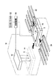
図2はレーザ描画装置の外観を示す斜視図である。略直方体のハウジング18には図1に示す光学ユニット12が収容される。ハウジング18の側面18aには開口30が形成され、この開口30を通って描画テーブル14がハウジング18内を進退する。側面18aにはY軸に沿って延びる2本のレール36および38が固定されており、レール36および38にそれぞれCCDカメラ32および34が鉛直下方に向かって取り付けられる。これらCCDカメラ32および34は、それぞれ制御装置50(図1参照)の指令信号に基づいてレール36および38に沿ってY軸に沿って移動し、そのY位置は制御装置50に常に監視されている。
【0023】
CCDカメラ32および34は可変焦点カメラであり、上述した描画処理に先立って行われるアラインメント処理に用いられる。アラインメント処理は、基板Sと回路パターンとを整合させるために、描画テーブル14において基板Sが本来置かれるべき位置と実際に搬送装置により置かれた位置とのずれ量を計測し、基板Sに対する描画すべき回路パターンの位置ずれが相殺されるように描画テーブル14の描画開始位置および光学ユニット12の走査開始位置を調整するものである。アラインメント処理では、描画テーブル14に対する基板Sの位置が、基板Sの四隅に形成された基準穴P1、P2、P3およびP4のX座標およびY座標により示される。以下、これらの座標データを相対位置データと称する。
【0024】
描画テーブル14は、X軸に沿って延びるレール(図示せず)上をモータ駆動により相対移動するXテーブル(図示せず)およびXテーブル上を水平面内でモータ駆動により回転するθテーブル(図示せず)の上に設けられ、制御装置50によってモータ駆動量即ち描画テーブル14のX位置およびθ位置が制御される。また、光学ユニット12は、基板Sの描画すべき範囲を含みかつその描画幅よりも広い範囲を走査することが可能であり、Y方向における走査開始位置は制御装置50によって制御される。制御装置50は、CCDカメラ32および34によって検出された基板Sの相対位置データに基づいて基板Sの位置ずれ量を算出し、この位置ずれが相殺されるように描画テーブル14の描画開始位置(X位置、θ位置)を調整すると共に、光学ユニット12から出射されるレーザビームの走査開始位置(Y位置)を調整する。
【0025】
レーザ描画装置10の制御装置50には、CAD/CAMシステム52から上記回路パターンのベクタデータの他、基板Sの外径寸法や基準穴P1〜P4の位置等の設計データが転送され、一時的にメモリ(図示せず)に格納される。制御装置50は、基板Sのハウジング18側においてY軸方向に並ぶ2つの基準穴P1−P2間の基準穴間距離L1を設計データに基づいて算出し、CCDカメラ32および34間の距離が基準穴間距離L1に一致するようにCCDカメラ32および34を位置決めする。
【0026】
そして、CCDカメラ32および34の撮影光学系(図示せず)が相対的に低倍率に設定され、CCDカメラ32によって基準穴P1が、CCDカメラ34によって基準穴P2が撮影され、この第1回目の撮影により得られた映像信号が制御装置50に送られ、ここで適当な画像処理、例えばパターンマッチング法により、描画テーブル14に対する基準穴P1およびP2の相対位置データ、詳しくはXY2次元直交座標系における基準穴P1およびP2の中心のX座標およびY座標が算出される。
【0027】
次に、基準穴P1およびP2がCCDカメラ32および34の視野の略中央に位置するように、CCDカメラ32および34のY軸方向位置が調整されると共に描画テーブル14のX軸方向位置および水平面内での回転方向θの位置が調整される。回転方向θの回転中心は描画テーブル14の中心に設定される。そしてCCDカメラ32および34の撮影光学系が第1回目の撮影よりも高倍率に設定される即ちズームアップされて第2回目の撮影が行われ、得られた映像信号から基準穴P1およびP2の相対位置データが求められる。第2回目の撮影ではCCDカメラ32および34がズームアップされているため、第2回目の撮影により得られる基準穴P1およびP2の相対位置データは、第1回目の撮影により得られる基準穴P1およびP2の相対位置データよりも高精度であるとみなすことができる。
【0028】
続いて、基準穴P3およびP4を撮影するために、描画テーブル14が描画開始位置に向かってX軸方向に移動させられる。その移動距離はX方向に並ぶ2つの基準穴P1およびP3の基準穴間距離L2(またはP2およびP4の基準穴間距離)に一致し、この基準穴間距離L2は設計データに基づいて求められる。そして、CCDカメラ32および34の撮影光学系が再び低倍率に設定され、CCDカメラ32によって基準穴P3が、CCDカメラ34によって基準穴P4が撮影され、制御装置50においてこの第3回目の撮影により得られた映像信号に基づいて描画テーブル14に対する基準穴P3およびP4の相対位置データが算出される。
【0029】
そして、基準穴P3およびP4がCCDカメラ32および34の視野の略中央に位置するように、CCDカメラ32および34のY軸方向位置と描画テーブル14のX軸方向位置およびθ方向位置とが調整され、CCDカメラ32および34の撮影光学系が高倍率に設定されて第4回目の撮影が行われ、得られた映像信号から基準穴P3およびP4の高精度な相対位置データが求められる。
【0030】
以上の動作により基準穴P1〜P4の高精度な相対位置データが得られると、制御装置50では、この相対位置データに基づいて基板SのX軸方向に関するずれ量X’、Y軸方向に関するずれ量Y’およびθ方向に関するずれ量θ’がそれぞれ求められ、アラインメント処理が終了し、上述した描画処理に進む。描画処理においては、アラインメント処理により求められたずれ量X’、Y’およびθ’に基づいて、描画テーブル14の描画開始位置が調整され、光学ユニット12のY軸方向に関する走査開始位置が調整される。即ち、描画テーブル14は設計上定められた描画開始位置よりもX軸に沿って調整量(−X’)だけ移動し、さらに回転中心周りに調整量(−θ’)だけ回転した位置から相対移動を開始し、光学ユニット12は設計上定められた走査開始位置よりも調整量(−Y’)だけ移動した位置から走査を開始することになる。
【0031】
このように、基準穴P1〜P4を相対的に視野の広い低倍率で予め撮影することにより、確実に基準穴P1〜P4が検出でき、また次に行う撮影では相対的に視野が狭いが高精細な画像が得られる高倍率にCCDカメラ32および34を設定するとともにその視野に基準穴P1〜P4が収まるようにCCDカメラ32、34および描画テーブル14を調整するため、高精度な相対位置データを確実に得ることができる。従って、個々の基板Sの外形寸法誤差や基準穴P1〜P4の穴加工誤差あるいは基板Sの搬送位置ずれ等の複合的な要因により、描画テーブル14に対する基準穴P1〜P4の位置が個々の基板Sで異なることがあっても、これらずれ量(X’、Y’、θ’)を確実に検出し、位置ずれを解消するように描画テーブル14および光学ユニット12が調整されるので、基板Sに対して回路パターンを確実かつ高精度に描画できる。また、基準穴P1〜P4が確実に計測されるので再計測の必要がなく作業効率の低下も防止される。
【0032】
なお、第1回目〜第4回目の撮影における倍率は特に限定されないが、第2回目および第4回目の撮影ではそのCCDカメラ32、34の視野の大きさが基準穴P1〜P4の大きさに許容加工誤差を加えたものであることが好ましい。例えば基準穴P1〜P4の直径が2mm、その許容加工誤差が0.5mmであった場合には、CCDカメラ32および34の視野が3mm四方程度の広さであることが好ましい。また、第1回目および第3回目の撮影ではそのCCDカメラ32および34の視野の大きさが基準穴P1〜P4の大きさに搬送誤差や加工誤差を加味したものであることが好ましい。
【0033】
図3は本発明の第2実施形態を示す図であって、レーザ描画装置の外観斜視図である。第2実施形態の描画システムは、CCDカメラが固定焦点カメラであり4台設けられること以外は第1実施形態と同様の構成であり、対応する構成については符号に200を加算して示している。
【0034】
レーザ描画装置210の側面218aの図中右方にはレール236が固定され、レール236には、互いに固定された2つのCCDカメラ232aおよび232bが取り付けられる。これらCCDカメラ232aおよび232bはX軸に沿って並んでおり、レール236に沿ってY軸に沿って一体的に移動する。CCDカメラ232aおよび232bは共に固定焦点カメラであり、CCDカメラ232aは相対的に高倍率に設定され、CCDカメラ232bは相対的に低倍率に設定される。側面218aの図中左方に設けられた2つのCCDカメラ234aおよび234bも同様の構成である。
【0035】
アラインメント処理では、低倍率のCCDカメラ232bおよび234bにより基準穴P1およびP2が撮影され、得られた映像信号から基準穴P1およびP2の大まかな相対位置データが求められる。そして、その大まかな相対位置データに基づいて、高倍率のCCDカメラ232aおよび234aの視野の略中央に基準穴P1およびP2が収まるように、CCDカメラ232aおよび234aがY軸に沿う方向に、描画テーブル14がX軸に沿う方向およびθ方向に調整される。そしてCCDカメラ232aおよび234aから得られた映像信号から基準穴P1〜P4の高精度な相対位置データが求められる。その後、描画テーブル214の移動後に基準穴P3およびP4が同様の手法で計測される。
【0036】
このように、第2実施形態のレーザ描画装置210によると、第1実施形態と同様、描画テーブル214に対する基準穴P1〜P4の位置が個々の基板Sで異なることがあっても、これらずれ量(X’、Y’およびθ’)を確実に検出し、位置ずれを解消するように描画テーブル214および光学ユニット(図示せず)が調整されるので、基板Sに対して回路パターンを確実かつ高精度に描画できる。また、基準穴P1〜P4が確実に計測されるので再計測の必要がなく作業効率の低下も防止される。
【0037】
図4は本発明の第3実施形態を示す図であって、レーザ描画装置の外観斜視図である。第3実施形態の描画システムは、CCDカメラが固定焦点カメラであることと基板エッジ検出センサが設けられること以外は第1実施形態と同様の構成であり、対応する構成については符号に300を加算して示している。
【0038】
基板エッジ検出センサ340、342および344は、描画テーブル314の上面に固設され、搬送されてきた基板Sの相対位置を検出するセンサである。基板エッジ検出センサ340、342および344は例えば公知の赤外線センサであるが、CCDカメラであってもよい。
【0039】
アラインメント処理において、基板エッジ検出センサ340および342により描画テーブル314に対する側辺Se1の位置即ち基板SのX軸方向に関する位置とθ回転方向に関する位置とが計測され、基板エッジ検出センサ342により描画テーブル314に対する側辺Se2の位置即ち基板SのY軸方向に関する位置が計測される。そして、図示しない制御装置において基板エッジ検出センサ340および342の相対位置データに基づいて、基板Sの描画テーブル314に対するずれ量(X’、Y’およびθ’)が求められる。
【0040】
次に、基板Sの描画テーブル314に対するずれ量X’、Y’およびθ’と、基準穴P1、P2の設計データとに基づいて、CCDカメラ332および334の視野の中央に基準穴P1およびP2が位置するように、CCDカメラ332および334がY軸方向に、描画テーブル314がX軸方向およびθ方向に調整させられた後、基準穴P1およびP2の撮影および高精度の相対位置データの算出が行われる。さらに描画テーブル314が基準穴P1およびP3間の距離分だけ描画開始位置に向かって移動させられ、基準穴P3およびP4が撮影され、基準穴P3およびP4の高精度な相対位置データが求められる。なお、CCDカメラ332および334は相対的に狭い視野を持つ高倍率の固定焦点カメラであり、その視野は基準穴P1〜P4の大きさに許容加工誤差を加えた大きさを有する。
【0041】
第3実施形態のレーザ描画装置310によると、基板エッジ検出センサ340および342により基板Sの相対位置を計測するので、アラインメント処理時のカメラ視野における位置ずれの要因は基板Sに対する基準穴P1〜P4の加工誤差あるいは基板Sの外径寸法誤差のみとなり、搬送時の位置ずれは実質的に解消される。従って、第1および第2実施形態よりも基板Sのずれ量(X’、Y’およびθ’)は少なく、低倍率のCCDカメラを用いて基準穴P1〜P4の大まかな相対位置データを求める必要がない。第3実施形態によれば、第1および第2実施形態と同様、描画テーブル214に対する基準穴P1〜P4の位置が個々の基板Sで異なることがあっても、位置ずれを解消するように描画テーブル214の位置および光学ユニット(図示せず)の走査開始位置が調整されるので、基板Sに対して回路パターンを確実かつ高精度に描画できる。
【0042】
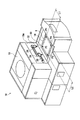
図5は本発明の第4実施形態を示す図であって、描画テーブルの斜視図である。第4実施形態の描画システムは、カメラが固定焦点カメラであることと当てつけピンおよび当てつけシリンダが設けられること以外は第1実施形態と同様の構成を備える。
【0043】
描画テーブル414には、固定ピン414aおよび414bと、当てつけシリンダ414cおよび414dとが設けられる。固定ピン414aは基板Sの側辺Se2に当接して基板SのY軸方向への移動を規制し、2つの固定ピン414bは基板Sの側辺Se1に当接して基板SのX軸方向への移動を規制する。当てつけシリンダ414cは基板Sの側辺Se3に当接し、基板Sを固定ピン414bに向かって押圧付勢する。当てつけシリンダ414dは基板Sの側辺Se4に当接し、基板Sを固定ピン414aに向かって押圧付勢する。これにより、基板Sは常に同じ位置に位置決めされ、搬送時の位置ずれが解消される。なお、図示しない2つのCCDカメラは高倍率の固定焦点カメラであり、相対的に狭い視野、具体的には基準穴P1〜P4の大きさに許容加工誤差を加えた大きさの視野を有する。
【0044】
第4実施形態の描画システムによると、固定ピン414a、414bおよび当てつけシリンダ414c、414dにより基板Sが描画テーブル414上の所定位置に高精度に位置決めされるため、アラインメント処理においてカメラ視野における位置ずれの要因は基板Sに対する基準穴P1〜P4の加工誤差あるいは基板Sの外径寸法誤差のみとなり、搬送時の位置ずれは実質的に解消される。従って、第1〜第3実施形態と同様、描画テーブル414に対する基準穴P1〜P4の位置が個々の基板Sで異なることがあっても、位置ずれを解消するように描画テーブル414の位置および光学ユニット(図示せず)の走査開始位置が調整されるので、基板Sに対して回路パターンを確実かつ高精度に描画できる。
【0045】
なお、固定ピン414a、414bおよび当てつけシリンダ414c、414dからなる基板位置決め機構を、図6に示す第5実施形態のように、固定ピン514bおよび当てつけスライドピン514a、514c、514dで構成してもよい。当てつけスライドピン514cは制御装置(図示せず)の制御信号に基づいてX軸方向に相対移動し、基板Sを側辺Se3から固定ピン514bに向かって押圧付勢する。当てつけスライドピン514aおよび514dはY軸方向に移動自在であり、それぞれ基板Sの側辺Se2およびSe4を押圧することにより基板Sを実質的に隙間なく挟持して所定の位置に位置決めする。
【0046】
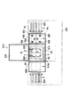
図7は本発明の第6実施形態を示す図であって、描画システムの上面図である。第6実施形態の描画システムは、CCDカメラが固定焦点カメラであり、搬送装置が基板Sを描画テーブルに載置する前に基準穴P1〜P4の大まかな相対位置データを求める点が異なること以外は第1実施形態と同様の構成を備え、対応する構成には符号に600を加算して示している。
【0047】
搬送装置620は、搬入用ベルト622と描画テーブル614との間にプリアラインメントテーブル626を備え、搬入用ベルト622に搬送された基板Sはまずプリアラインメントテーブル650の所定位置に置かれる。プリアラインメントテーブル650に置かれた基板Sの四隅の鉛直上方には4台のCCDカメラ652、654、656および658が配される。アラインメント処理では、これらCCDカメラ652、654、656および658により基準穴P1〜P4が撮影され、得られた映像信号を画像処理することにより基板Sに対する基準穴P1〜P4の相対位置データが求められる。CCDカメラ652、654、656および658は相対的に低倍率の固定焦点カメラである。
【0048】
これら基準穴P1〜P4の相対位置データはレーザ描画装置610を制御する制御装置に転送され、また基板Sは描画テーブル614の所定位置に移動させられる。そして、搬送装置620から転送された相対位置データとCAD/CAMシステムから転送された設計データとに基づいて、CCDカメラ632および634の視野の中央に基準点P1〜P4が位置するように、描画テーブル614およびCCDカメラ632、634が調整された後、基準穴P1〜P4が撮影され、描画テーブル614に対する基準穴P1〜P4の高精度な相対位置データが求められる。CCDカメラ632、634は相対的に高倍率の固定焦点カメラである。
【0049】
第6実施形態の描画システムによると、描画テーブル614への搬送前に基板Sに対する基準穴P1〜P4の大まかな相対位置を計測し、描画テーブル614に載置したときには基板Sに対する基準穴P1〜P4の位置ずれが相殺されるように描画テーブル614およびCCDカメラ632、634が調整されるので、描画テーブル614に置かれた基板Sに関してカメラ視野における基準穴P1〜P4の位置ずれの要因は基板Sの搬送時の位置ずれのみとなり、穴加工誤差や外径寸法誤差は実質的に解消される。従って、第1〜第5実施形態と同様、描画テーブル614に対する基準穴P1〜P4の位置が個々の基板Sで異なることがあっても、位置ずれを解消するように描画テーブル614の位置および光学ユニット(図示せず)の走査開始位置が調整されるので、基板Sに対して回路パターンを確実かつ高精度に描画できる。
【0050】
図8は、本発明の第7実施形態を示す図であって、描画システムの斜視図である。第7実施形態の描画システムは、搬送装置が基板Sを描画テーブルに載置する前に基準穴P1〜P4の高精度な相対位置データを求める点が異なること以外は第6実施形態と同様の構成を備え、対応する構成には符号にさらに100を加算して示している。
【0051】
搬送装置720のプリアラインメントテーブル726の上方には、4台のCCDカメラ752、754、756および758が設けられる。CCDカメラ752、754、756および758は可変焦点カメラであり、X軸方向およびY軸方向に相対移動可能である。搬送装置720は、これらCCDカメラ752、754、756および758を低倍率に設定して得られた映像信号に基づいて、基板Sの4つの基準穴P1〜P4の大まかな相対位置を特定し、次にCCDカメラ752、754、756および758をそれぞれ対応する基準穴P1〜P4が捕らえられる位置に移動させ、さらにCCDカメラ752、754、756および758を高倍率に設定して得られた映像信号に基づいて、プリアラインメントテーブル726に対する4つの基準穴P1〜P4の高精度な相対位置データを得る。そして、図示しない制御装置は、基準穴P1〜P4の高精度な相対位置データに基づいて、レーザ描画装置710における描画テーブル714のX軸方向調整量(−X’)およびθ方向調整量(−θ’)とレーザ光学系のY軸方向調整量(−Y’)とが算出される。
【0052】
プリアラインメントテーブル726は図示しない駆動機構によりθ回転可能であり、θ方向調整量(−θ’)分だけ調整される。プリアラインメントテーブル726においてθ方向に位置調整された基板Sは、第1実施形態で説明したような吸着パッドを用いた移送機構(図示せず)により描画テーブル714へ移送され、θ方向に関しては位置調整されたままの状態で描画テーブル714に位置決めされる。移送機構の移送精度はミクロンオーダであり、その移動量は制御装置により監視、制御される。
【0053】
制御装置によって求められたX軸方向調整量(−X’)およびY軸方向調整量(−Y’)のデータは、レーザ描画装置710に転送される。レーザ描画装置710は転送されたX軸方向調整量(−X’)に基づいて描画テーブル714の描画開始位置を調整し、Y軸方向調整量(−Y’)に基づいてレーザ光学系(図示せず)の走査開始位置を調整する。
【0054】
このように、第7実施形態の露光システムによると、レーザ描画装置710にカメラ計測機能およびθ回転駆動機構を設けなくてもよいので、第6実施形態よりもレーザ描画装置710の構成が簡単になり、また描画作動に要する時間も短縮される。
【0055】
なお、第1〜第7実施形態において基板Sとして4個の基準穴が設けられているものを用いているが、3個の基準穴が形成された基板の描画にも適用可能である。
【0056】
【発明の効果】
以上説明したように本発明の描画装置は、確実かつ高精度に回路パターンを描画するとともに作業効率を向上させることができる。
【図面の簡単な説明】
【図1】本発明の第1実施形態の描画システムを簡略して示す図である。
【図2】図1に示すレーザ描画装置の外観を示す斜視図である。
【図3】本発明の第2実施形態のレーザ描画装置を示す斜視図である。
【図4】本発明の第3実施形態のレーザ描画装置を示す斜視図である。
【図5】本発明の第4実施形態を示す図であって、レーザ描画装置の描画テーブルを示す斜視図である。
【図6】本発明の第5実施形態を示す図であって、レーザ描画装置の描画テーブルを示す斜視図である。
【図7】本発明の第6実施形態の描画システムを示す上面図である。
【図8】本発明の第7実施形態の描画システムを示す斜視図である。
【符号の説明】
10 レーザ描画装置
12 光学ユニット
14 描画テーブル
50 制御装置
S 基板
P1、P2、P3、P4 基準穴[0001]
TECHNICAL FIELD OF THE INVENTION
The present invention relates to a laser writing apparatus that directly draws a circuit pattern on an object to be drawn by using a laser beam, and a writing system using the laser writing apparatus.
[0002]
[Prior art]
The laser drawing apparatus as described above is used in a drawing system for forming a fine circuit pattern on the surface of a substrate in, for example, a manufacturing process of an automated printed circuit board. As a conventional example, Japanese Patent Application Laid-Open No. 10-162145 discloses No. In a writing system, a photosensitive object to be drawn, for example, a substrate provided with a photoresist layer on its surface is transported to a laser writing apparatus, and the photoresist layer is exposed in the laser writing apparatus. Specifically, CAD / CAM is used. The laser beam is modulated according to the raster data of the circuit pattern designed / edited by the system, and only the circuit pattern portion of the photoresist layer is photo-cured by raster scanning, whereby the circuit pattern is directly drawn on the photoresist layer. After drawing, the uncured photoresist on the substrate discharged from the laser drawing device is washed away with a solvent and treated with a chemical that corrodes copper, etc., and the portion where the photoresist remains adhered remains without being corroded. Thus, the same circuit pattern as the designed circuit pattern is formed on the substrate.
[0003]
By the way, in the laser drawing apparatus, the substrate is placed on the drawing table, and the drawing table, that is, the substrate is relatively moved in the sub-scanning direction while the laser beam is deflected in the main scanning direction with respect to the substrate on the drawing table. The drawing is performed by. Since a laser drawing apparatus is required to always draw a circuit pattern on a plurality of substrates of the same standard at the same position, conventionally, a relative position of a reference hole having a predetermined hole diameter formed on the substrate with respect to a drawing table is determined by a CCD camera. And the like, and by controlling the drawing start position based on the obtained relative position data, each substrate and the circuit pattern are matched. The CCD camera is installed at a position away from the substrate by a certain distance, and its focal length is fixed.
[0004]
In recent years, as the precision and density of circuit patterns have increased, the drawing accuracy required for laser writing apparatuses has become on the order of microns, and there is a demand for increasing the measurement accuracy of reference holes. As a method for solving this problem, for example, it is conceivable to increase the magnification of the CCD camera. However, in this case, since the field of view of the CCD camera is narrowed, a phenomenon that the reference hole is out of the field of view and measurement becomes impossible easily occurs. This is because the position of the reference hole with respect to the drawing table may be different for each substrate due to various factors such as an outer dimension error of each substrate, a hole processing error of the reference hole, or a displacement of the transfer position of the substrate. For the substrate for which the reference hole could not be measured, the measurement had to be performed again or discarded as a defective product, resulting in a decrease in work efficiency.
[0005]
[Problems to be solved by the invention]
SUMMARY OF THE INVENTION The present invention has been made in view of the above problems, and it is an object of the present invention to draw a circuit pattern reliably and accurately and to improve work efficiency.
[0006]
[Means for Solving the Problems]
The drawing apparatus of the present invention scans a photosensitive object to be drawn placed on a table in a main scanning direction with a laser beam emitted from a scanning optical system, and relatively moves the table in a sub-scanning direction. A laser drawing device that draws a circuit pattern on the surface of a drawing object, a transfer device that transfers the drawing target object to the table, a positional shift that occurs when the drawing target object is transferred to the table, and an outer dimension error of the drawing target object, The most main feature of the present invention is to provide a matching means for resolving a processing error of a reference hole formed in a drawing object and matching a circuit pattern with the drawing object.
[0007]
The aligning means of the exposure system includes, for example, a variable focus camera provided in a laser drawing apparatus and imaging a reference hole, and an image processing means for obtaining relative position data of the reference hole with respect to the table based on an image obtained by the variable focus camera, Adjusting means for adjusting the drawing start position of the table and the scanning start position of the laser beam based on the relative position data, and is preferably obtained when the variable focus camera is set to the first magnification and the image is taken. The reference hole is detected based on the image, the table and the variable focus camera are relatively moved to position the reference hole at the center of the field of view of the variable focus camera, and the variable focus camera is set at a second magnification higher than the first magnification. Relative position data is obtained based on an image obtained when setting and imaging.
[0008]
The aligning means of the exposure system includes, for example, a first fixed-focus camera provided in the laser drawing device for imaging the reference hole at a first magnification, and a second fixed focus camera provided in the laser drawing device for setting the reference hole higher than the first magnification. A second fixed-focus camera that captures an image at a magnification of?, Image processing means for obtaining relative position data of a reference hole with respect to a table based on an image obtained by the second fixed-focus camera, and drawing of a table based on the relative position data Adjusting means for adjusting the start position and the scanning start position of the laser beam. Preferably, the reference hole is detected based on an image taken by the first fixed focus camera, and the table and the second fixed focus camera are detected. Are relatively moved to position the reference hole at the center of the field of view of the second fixed focus camera, and the relative position data is further determined based on the image captured by the second fixed focus camera. The seek.
[0009]
The aligning means of the exposure system includes, for example, a sensor for detecting the relative position of the outer peripheral edge of the object to be drawn with respect to the table, a fixed focus camera provided in the laser writing apparatus and imaging a reference hole at a predetermined magnification, and a fixed focus camera. Image processing means for obtaining relative position data of a reference hole with respect to a table based on an obtained image, and adjusting means for adjusting a drawing start position and a laser beam scanning start position of a table based on a detection result of a sensor and relative position data. May be provided.
[0010]
The aligning means of the exposure system includes, for example, a fixed member provided on a table and abutting on one side surface of the object to be drawn, an urging member for urging the object to be drawn toward the fixed member, and a reference member provided on the laser drawing apparatus. A fixed-focus camera that captures an image of the hole at a predetermined magnification; image processing means for obtaining relative position data of the reference hole with respect to the table based on an image obtained by the fixed-focus camera; a drawing start position of the table based on the relative position data; Adjusting means for adjusting the scanning start position of the laser beam may be provided, preferably after positioning the object to be drawn on the table in cooperation with the fixed member and the urging member, to the image captured by the fixed focus camera The relative position data is obtained based on the relative position data.
[0011]
The aligning means of the exposure system includes, for example, a first fixed focus camera provided in the transport device for imaging the reference hole at a first magnification, and a second fixed focus camera provided in the laser drawing device for setting the reference hole higher than the first magnification. A second fixed-focus camera for imaging at a magnification, image processing means for obtaining relative position data of a reference hole with respect to the table based on an image obtained by the second fixed-focus camera, and drawing of a table based on the relative position data Adjusting means for adjusting the position and the scanning start position of the laser beam. Preferably, the reference hole is detected based on an image captured by the first fixed focus camera in the transport device, and the laser drawing device is detected from the transport device. And the table and the second fixed focus camera are relatively moved based on the detection result of the reference hole to move the reference hole to the second fixed focus camera. Of positioning the center of the field of view, further second fixed focus camera determine the relative position data based on the video imaged.
[0012]
The aligning means of the exposure system includes, for example, a variable focus camera provided in the transport device for imaging the reference hole, an image processing means for obtaining relative position data of the reference hole with respect to the table based on an image obtained by the variable focus camera, Adjusting means for adjusting the drawing start position of the table and the scanning start position of the laser beam based on the position data may be provided. , The reference hole is detected at the center of the field of view of the variable focus camera by relatively moving the variable focus camera, and the variable focus camera is positioned at the second magnification higher than the first magnification. After the relative position data is obtained based on the image obtained when the image is set and set, the relative position data is provided to the laser drawing apparatus.
[0013]
BEST MODE FOR CARRYING OUT THE INVENTION
Hereinafter, embodiments of the present invention will be described with reference to the accompanying drawings.
[0014]
FIG. 1 is a view showing a first embodiment of the present invention, and is a view showing a simplified drawing system.
The drawing system includes a
[0015]
The
[0016]
An XY two-dimensional orthogonal coordinate system which is immovable with respect to the machine frame of the laser writing apparatus is set on the moving plane of the drawing table 14, and the X axis of this coordinate system extends in the sub-scanning direction, and the Y axis is the main scanning direction. Extending in the direction. The origin of the XY two-dimensional rectangular coordinate system is set at the lower right corner of the drawing table 14 in the drawing. Further, the transport direction of the substrate S by the transport device is parallel to the Y axis.
[0017]
The drawing system further includes a
[0018]
The operation of the
[0019]
Next, the substrate S is moved by the drawing table 14 from the preparation position to the drawing start position, that is, to the positive side of the X axis. At this time, an alignment process for matching the individual substrates S and the circuit patterns is performed prior to the drawing process.
[0020]
Then, after reaching the drawing start position, the drawing table 14 is moved from the drawing start position indicated by the broken line to the preparation position indicated by the solid line, that is, by a small amount in the negative direction of the X axis. A drawing process is performed. In this drawing process, the substrate S is scanned by the laser beam modulated by the
[0021]
When the drawing process is completed, the drawn substrate S is released from the clamp member from the drawing table 14 returned to the preparation position, and is discharged to the
[0022]
FIG. 2 is a perspective view showing the appearance of the laser drawing apparatus. The
[0023]
The
[0024]
The drawing table 14 includes an X table (not shown) relatively moved by a motor drive on a rail (not shown) extending along the X axis, and a θ table (not shown) rotated on the X table in a horizontal plane by a motor drive. And the
[0025]
The CAD /
[0026]
Then, the photographing optical systems (not shown) of the
[0027]
Next, the positions of the
[0028]
Subsequently, in order to image the reference holes P3 and P4, the drawing table 14 is moved in the X-axis direction toward the drawing start position. The moving distance coincides with the reference hole distance L2 between two reference holes P1 and P3 arranged in the X direction (or the reference hole distance between P2 and P4), and the reference hole distance L2 is obtained based on design data. . Then, the photographing optical systems of the
[0029]
Then, the Y-axis position of the
[0030]
When the highly accurate relative position data of the reference holes P1 to P4 is obtained by the above operation, the
[0031]
In this way, by previously photographing the reference holes P1 to P4 at a low magnification with a relatively wide field of view, the reference holes P1 to P4 can be detected with certainty. Since the
[0032]
Note that the magnification in the first to fourth photographing is not particularly limited, but in the second and fourth photographing, the size of the field of view of the
[0033]
FIG. 3 is a view showing a second embodiment of the present invention, and is an external perspective view of a laser drawing apparatus. The drawing system of the second embodiment has the same configuration as that of the first embodiment except that four CCD cameras are fixed focus cameras and four CCD cameras are provided, and corresponding components are shown by adding 200 to the reference numerals. .
[0034]
A
[0035]
In the alignment process, the reference holes P1 and P2 are photographed by the low-
[0036]
As described above, according to the
[0037]
FIG. 4 is a view showing a third embodiment of the present invention, and is an external perspective view of a laser drawing apparatus. The drawing system of the third embodiment has the same configuration as that of the first embodiment except that the CCD camera is a fixed focus camera and a substrate edge detection sensor is provided. For the corresponding configuration, 300 is added to the reference numeral. Is shown.
[0038]
The substrate
[0039]
In the alignment processing, the position of the side Se1 with respect to the drawing table 314, that is, the position of the substrate S in the X-axis direction and the position of the substrate S in the θ rotation direction are measured by the substrate
[0040]
Next, based on the displacement amounts X ′, Y ′ and θ ′ of the substrate S with respect to the drawing table 314 and the design data of the reference holes P1 and P2, the reference holes P1 and P2 After the
[0041]
According to the
[0042]
FIG. 5 is a diagram showing the fourth embodiment of the present invention, and is a perspective view of a drawing table. The drawing system of the fourth embodiment has the same configuration as that of the first embodiment except that the camera is a fixed-focus camera and that an attaching pin and an attaching cylinder are provided.
[0043]
The drawing table 414 is provided with fixing
[0044]
According to the drawing system of the fourth embodiment, the substrate S is accurately positioned at a predetermined position on the drawing table 414 by the fixing
[0045]
The substrate positioning mechanism including the fixing
[0046]
FIG. 7 is a diagram showing the sixth embodiment of the present invention, and is a top view of the drawing system. The drawing system of the sixth embodiment is different from the drawing system in that the CCD camera is a fixed focus camera, and the transfer device obtains rough relative position data of the reference holes P1 to P4 before placing the substrate S on the drawing table. Has a configuration similar to that of the first embodiment, and the corresponding configuration is shown by adding 600 to the reference numerals.
[0047]
The
[0048]
The relative position data of the reference holes P1 to P4 is transferred to a control device that controls the laser drawing device 610, and the substrate S is moved to a predetermined position on the drawing table 614. Then, based on the relative position data transferred from the
[0049]
According to the drawing system of the sixth embodiment, the rough relative positions of the reference holes P1 to P4 with respect to the substrate S are measured before the transfer to the drawing table 614. Since the drawing table 614 and the
[0050]
FIG. 8 is a view showing the seventh embodiment of the present invention, and is a perspective view of a drawing system. The drawing system of the seventh embodiment is the same as the sixth embodiment except that the transfer apparatus obtains high-precision relative position data of the reference holes P1 to P4 before placing the substrate S on the drawing table. The configuration is provided, and the corresponding configuration is shown by adding 100 to the reference numeral.
[0051]
Above the pre-alignment table 726 of the
[0052]
The pre-alignment table 726 is rotatable by θ by a drive mechanism (not shown), and is adjusted by the θ-direction adjustment amount (−θ ′). The substrate S whose position is adjusted in the θ direction in the pre-alignment table 726 is transferred to the drawing table 714 by a transfer mechanism (not shown) using a suction pad as described in the first embodiment, and the position in the θ direction is adjusted. It is positioned on the drawing table 714 while being adjusted. The transfer accuracy of the transfer mechanism is on the order of microns, and the amount of movement is monitored and controlled by a controller.
[0053]
The data of the X-axis direction adjustment amount (−X ′) and the Y-axis direction adjustment amount (−Y ′) obtained by the control device are transferred to the
[0054]
As described above, according to the exposure system of the seventh embodiment, since the
[0055]
In the first to seventh embodiments, a substrate provided with four reference holes is used as the substrate S. However, the present invention can be applied to drawing of a substrate on which three reference holes are formed.
[0056]
【The invention's effect】
As described above, the drawing apparatus of the present invention can draw a circuit pattern reliably and with high accuracy and can improve work efficiency.
[Brief description of the drawings]
FIG. 1 is a diagram schematically illustrating a drawing system according to a first embodiment of the present invention.
FIG. 2 is a perspective view showing an appearance of the laser drawing apparatus shown in FIG.
FIG. 3 is a perspective view showing a laser drawing apparatus according to a second embodiment of the present invention.
FIG. 4 is a perspective view showing a laser writing apparatus according to a third embodiment of the present invention.
FIG. 5 is a perspective view illustrating a drawing table of a laser drawing apparatus according to a fourth embodiment of the present invention.
FIG. 6 is a view showing a fifth embodiment of the present invention, and is a perspective view showing a drawing table of a laser drawing apparatus.
FIG. 7 is a top view illustrating a drawing system according to a sixth embodiment of the present invention.
FIG. 8 is a perspective view illustrating a drawing system according to a seventh embodiment of the present invention.
[Explanation of symbols]
10 Laser drawing equipment
12 Optical unit
14 Drawing table
50 Control device
S substrate
P1, P2, P3, P4 Reference hole
Claims (7)
前記テーブルに前記被描画体を搬送する搬送装置と、
前記被描画体の前記テーブルへの搬送時に生じる位置ずれと、前記被描画体の外形寸法誤差と、前記被描画体に形成された基準穴の加工誤差とを解消して、前記被描画体に対して前記回路パターンを整合させる整合手段を備えることを特徴とする描画システム。The photosensitive object to be drawn placed on the table is scanned in the main scanning direction by a laser beam emitted from the scanning optical system, and the table is relatively moved in the sub-scanning direction, so that the surface of the object to be drawn is moved. A laser drawing apparatus for drawing a circuit pattern,
A transfer device for transferring the object to be drawn to the table,
The position shift occurring when the object to be drawn is conveyed to the table, the outer dimension error of the object to be drawn, and the processing error of the reference hole formed in the object to be drawn are eliminated, and the object to be drawn is removed. And a matching system for matching the circuit pattern.
前記可変焦点カメラを第1の倍率に設定して撮像したときに得られる映像に基づいて前記基準穴を検出し、前記テーブルおよび前記可変焦点カメラを相対移動させて前記基準穴を前記可変焦点カメラの視野の中央に位置決めし、さらに前記可変焦点カメラを前記第1の倍率より高い第2の倍率に設定して撮像したときに得られる映像に基づいて前記相対位置データを求めることを特徴とする請求項1に記載の描画システム。A variable focus camera that is provided in the laser drawing device and captures the reference hole, and an image processing unit that obtains relative position data of the reference hole with respect to the table based on an image obtained by the variable focus camera; An adjustment unit that adjusts a drawing start position of the table and a scanning start position of the laser beam based on the relative position data,
The reference hole is detected based on an image obtained when the variable focus camera is set to a first magnification and imaged, and the table and the variable focus camera are relatively moved to move the reference hole to the variable focus camera. And the relative position data is obtained based on an image obtained when the variable focus camera is set to a second magnification higher than the first magnification and imaged. The drawing system according to claim 1.
前記第1の固定焦点カメラが撮像した映像に基づいて前記基準穴を検出し、前記テーブルおよび前記第2の固定焦点カメラを相対移動させて前記基準穴を前記第2の固定焦点カメラの視野の中央に位置決めし、さらに前記第2の固定焦点カメラが撮像した映像に基づいて前記相対位置データを求めることを特徴とする請求項1に記載の描画システム。A first fixed-focus camera provided in the laser drawing device for capturing the reference hole at a first magnification, and a second fixed focus camera provided in the laser drawing device, the reference hole being higher than the first magnification. A second fixed focus camera for imaging at a magnification of 2, image processing means for obtaining relative position data of the reference hole with respect to the table based on an image obtained by the second fixed focus camera, Adjusting means for adjusting the drawing start position of the table and the scanning start position of the laser beam based on the
The reference hole is detected based on an image captured by the first fixed-focus camera, and the table and the second fixed-focus camera are relatively moved to move the reference hole into the field of view of the second fixed-focus camera. 2. The drawing system according to claim 1, wherein the relative position data is obtained based on an image captured by the second fixed-focus camera, which is positioned at a center. 3.
前記固定部材および前記付勢部材との協働によって前記テーブルに前記被描画体を位置決めした後に、前記に前記固定焦点カメラが撮像した映像に基づいて前記相対位置データを求めることを特徴とする請求項1に記載の描画システム。A fixing member provided on the table and in contact with one side surface of the object to be drawn; an urging member for urging the object to be drawn toward the fixing member; A fixed focus camera that images the reference hole at a predetermined magnification, image processing means for obtaining relative position data of the reference hole with respect to the table based on an image obtained by the fixed focus camera, and Adjusting means for adjusting the drawing start position of the table and the scanning start position of the laser beam,
After positioning the object to be drawn on the table in cooperation with the fixed member and the urging member, the relative position data is obtained based on an image captured by the fixed focus camera. Item 2. The drawing system according to Item 1.
前記搬送装置において前記第1の固定焦点カメラが撮像した映像に基づいて前記基準穴を検出し、前記搬送装置から前記レーザ描画装置に前記被描画体を搬送すると共に、前記基準穴の検出結果に基づいて前記テーブルおよび前記第2の固定焦点カメラを相対移動させて前記基準穴を前記第2の固定焦点カメラの視野の中央に位置決めし、さらに前記第2の固定焦点カメラが撮像した映像に基づいて前記相対位置データを求めることを特徴とする請求項1に記載の描画システム。A first fixed focus camera provided in the transfer device for capturing the reference hole at a first magnification, and a second fixed focus camera provided in the laser drawing device and having the reference hole higher than the first magnification; A second fixed focus camera that captures an image at a magnification of?, Image processing means for obtaining relative position data of the reference hole with respect to the table based on an image obtained by the second fixed focus camera, and Adjusting means for adjusting the drawing start position of the table and the scanning start position of the laser beam,
The transport device detects the reference hole based on the image captured by the first fixed focus camera, and transports the object to be drawn from the transport device to the laser drawing device, and further includes a detection result of the reference hole. Relative movement of the table and the second fixed-focus camera to position the reference hole at the center of the field of view of the second fixed-focus camera, and further based on an image captured by the second fixed-focus camera. The drawing system according to claim 1, wherein the relative position data is obtained by calculating the relative position data.
前記搬送装置において、前記可変焦点カメラを第1の倍率に設定して撮像したときに得られる映像に基づいて前記基準穴を検出し、前記可変焦点カメラを相対移動させて前記基準穴を前記可変焦点カメラの視野の中央に位置決めし、さらに前記可変焦点カメラを前記第1の倍率より高い第2の倍率に設定して撮像したときに得られる映像に基づいて前記相対位置データを求めた後、前記相対位置データを前記レーザ描画装置に与えることを特徴とする請求項1に記載の描画システム。A variable focus camera that is provided in the transporting device and captures the reference hole, and an image processing unit that obtains relative position data of the reference hole with respect to the table based on an image obtained by the variable focus camera; Adjustment means for adjusting a drawing start position of the table and a scanning start position of the laser beam based on the relative position data,
In the transfer device, the reference hole is detected based on an image obtained when the variable focus camera is set to a first magnification and imaged, and the variable focus camera is relatively moved to change the reference hole. After positioning at the center of the field of view of the focus camera and further calculating the relative position data based on an image obtained when the variable focus camera is set to a second magnification higher than the first magnification and imaged, The drawing system according to claim 1, wherein the relative position data is provided to the laser drawing device.
Priority Applications (1)
| Application Number | Priority Date | Filing Date | Title |
|---|---|---|---|
| JP2002243275A JP2004085664A (en) | 2002-08-23 | 2002-08-23 | Drawing system |
Applications Claiming Priority (1)
| Application Number | Priority Date | Filing Date | Title |
|---|---|---|---|
| JP2002243275A JP2004085664A (en) | 2002-08-23 | 2002-08-23 | Drawing system |
Publications (1)
| Publication Number | Publication Date |
|---|---|
| JP2004085664A true JP2004085664A (en) | 2004-03-18 |
Family
ID=32052075
Family Applications (1)
| Application Number | Title | Priority Date | Filing Date |
|---|---|---|---|
| JP2002243275A Pending JP2004085664A (en) | 2002-08-23 | 2002-08-23 | Drawing system |
Country Status (1)
| Country | Link |
|---|---|
| JP (1) | JP2004085664A (en) |
Cited By (6)
| Publication number | Priority date | Publication date | Assignee | Title |
|---|---|---|---|---|
| JP2006267191A (en) * | 2005-03-22 | 2006-10-05 | Pentax Industrial Instruments Co Ltd | Exposure device |
| JP2006292955A (en) * | 2005-04-08 | 2006-10-26 | V Technology Co Ltd | Scan exposure method and apparatus |
| JP2006308996A (en) * | 2005-04-28 | 2006-11-09 | Fuji Photo Film Co Ltd | Exposure device |
| WO2006118343A1 (en) * | 2005-04-28 | 2006-11-09 | Fujifilm Corporation | Exposure apparatus |
| JP2008083520A (en) * | 2006-09-28 | 2008-04-10 | Fujifilm Corp | Exposure apparatus and alignment method |
| JP2009152415A (en) * | 2007-12-20 | 2009-07-09 | Ngk Spark Plug Co Ltd | Method of manufacturing ceramic component |
-
2002
- 2002-08-23 JP JP2002243275A patent/JP2004085664A/en active Pending
Cited By (6)
| Publication number | Priority date | Publication date | Assignee | Title |
|---|---|---|---|---|
| JP2006267191A (en) * | 2005-03-22 | 2006-10-05 | Pentax Industrial Instruments Co Ltd | Exposure device |
| JP2006292955A (en) * | 2005-04-08 | 2006-10-26 | V Technology Co Ltd | Scan exposure method and apparatus |
| JP2006308996A (en) * | 2005-04-28 | 2006-11-09 | Fuji Photo Film Co Ltd | Exposure device |
| WO2006118343A1 (en) * | 2005-04-28 | 2006-11-09 | Fujifilm Corporation | Exposure apparatus |
| JP2008083520A (en) * | 2006-09-28 | 2008-04-10 | Fujifilm Corp | Exposure apparatus and alignment method |
| JP2009152415A (en) * | 2007-12-20 | 2009-07-09 | Ngk Spark Plug Co Ltd | Method of manufacturing ceramic component |
Similar Documents
| Publication | Publication Date | Title |
|---|---|---|
| US20130055541A1 (en) | Workpiece transfer apparatus, workpiece mounting apparatus and workpiece mounting method | |
| JP2002310929A (en) | Defect inspecting device | |
| JP2008270696A (en) | Component mounting position correcting method and component mounting apparatus | |
| KR20160134494A (en) | Laser processing apparatus | |
| JP2004528591A (en) | Method and apparatus for registration control in manufacturing by imaging | |
| JP2010245508A (en) | Wafer alignment device and wafer alignment method | |
| TW202217470A (en) | Exposure control for photolithographic direct exposure procedures in pcb manufacturing | |
| KR102034481B1 (en) | Mounting method and mounting apparatus of electronic parts | |
| US20040150823A1 (en) | Exposure apparatus and aligning method | |
| JP2009054759A (en) | Abnormality detecting method and device | |
| JPH11214900A (en) | Method a and system for correcting deviation of camera positions and dummy part for correcting camera positions | |
| JP5755502B2 (en) | Position recognition camera and position recognition apparatus | |
| JP2008070135A (en) | Detecting method of optical axis shift of imaging apparatus and part position detecting method and device | |
| JP2004085664A (en) | Drawing system | |
| JP3613055B2 (en) | Substrate alignment method in screen printing | |
| JP2004146776A (en) | Machine and method for mounting flip-chip | |
| JP4902305B2 (en) | Exposure apparatus and alignment method | |
| JP2001124700A (en) | Calibration method of inspection machine with line sensor camera | |
| JP3463579B2 (en) | Electronic component mounting device with bump | |
| JP4631497B2 (en) | Proximity exposure equipment | |
| JPH10326997A (en) | Electronic component mounting device and method of correcting position by electronic component mounting device | |
| JPH11221690A (en) | Laser beam machine, and laser beam machining method | |
| JP2001518723A (en) | Method and apparatus for detecting position of lead terminal and / or edge of component | |
| JPH09283403A (en) | Aligner | |
| TWI835495B (en) | Electrical inspection equipment and electrical inspection method |
Legal Events
| Date | Code | Title | Description |
|---|---|---|---|
| A621 | Written request for application examination |
Free format text: JAPANESE INTERMEDIATE CODE: A621 Effective date: 20050511 |
|
| A711 | Notification of change in applicant |
Free format text: JAPANESE INTERMEDIATE CODE: A711 Effective date: 20060830 |
|
| A977 | Report on retrieval |
Free format text: JAPANESE INTERMEDIATE CODE: A971007 Effective date: 20080701 |
|
| A131 | Notification of reasons for refusal |
Free format text: JAPANESE INTERMEDIATE CODE: A131 Effective date: 20080722 |
|
| A02 | Decision of refusal |
Free format text: JAPANESE INTERMEDIATE CODE: A02 Effective date: 20081118 |