【0001】
【発明の属する技術分野】
この発明は、回転電機、特に永久磁石モータに使用される固定子及びその製造方法に関するものである。
【0002】
【従来の技術】
永久磁石がロータに配置された永久磁石モータの固定子のティースには、集中巻コイルが使用される。集中巻コイルは、1つのティースに電線が巻回されるコイルをいい、例えば特開平9−308142号公報に示されている。
この種のコイルでは、電磁振動などにより電線が動いて、層間短絡を起こしたり、スロット絶縁が破壊されて地絡したりする虞れがあるため、電線は確実に固定される必要がある
【0003】
従来から、固定子コイルの巻線を固定するため、巻線後真空含浸又は浸漬含浸する手段が用いられている。真空含浸の場合、ワークの形状によらずワニスが最もよく浸透し、信頼性の高いコイルが得られるが、ワニス硬化後に不要部分に付着したワニスを除去する作業が生じ、加工時間が増大する。また、浸漬含浸は、真空含浸ほど高価な設備が不要であるため、含浸設備が簡略化できるという長所があるが、コイルの線径が細く、巻数が多いものについては、ワニスが浸透しにくい。
【0004】
これらの含浸手段を改善するものとして、自己融着性電線を使用したコイルも多数用いられている。この手段によると、巻線後の乾燥工程だけで、手入れ作業がほとんど不要になるため、加工時間が大幅に短縮する。
図7は例えば特開平5−68359号公報に示された固定子コイル部分の横断面図であり、自己融着性薄葉材からなるスロット絶縁材9と、自己融着性電線10を複数回巻回してなる固定子コイルが示されている。
【0005】
すなわち、スロットの内壁面に沿って、あらかじめスロット絶縁材9を挿入しておき、その内側に自己融着性電線10を複数回巻回した後、スロットの開口部をふさぐように、自己融着性薄葉材からなるくさび11を挿入後、加熱処理されるものである。
【0006】
【発明が解決しようとする課題】
上記のような従来の回転電機の固定子では、自己融着性電線10を巻回した後、乾燥させるようにしているため、巻線の張力が加えられないコイルの直線部分に空間が生じやすく、長期間に渡る稼動中に電線が動いて、その部分が起点となって疲労破断したり、層間短絡等の事故に発展したりする可能性があるという問題点がある。
【0007】
この発明は上記問題点を解消するためになされたもので、電線を確実に固定し、しかも効率良く作業できるようにした回転電機の固定子及びその製造方法を提供することを目的とする。
【0008】
【課題を解決するための手段】
この発明の第1発明に係る回転電機の固定子は、リング状の固定子コアの内側に複数のティースが突出し、このティースに電線が複数層巻回されたものにおいて、上記巻回された電線の各層間に介在し、上記電線を結束するテープを備えたものである。
【0009】
また、第2発明に係る回転電機の固定子は、第1発明のものにおいて、テープを、プリプレグテープとしたものである。
【0010】
また、第3発明に係る回転電機の固定子の製造方法は、屈曲可能に連結されそれぞれ突出するティースを有する複数のコア部材を、上記ティースが外側となるような円弧状に形成する工程と、上記のように形成されたコア部材のティースに電線を巻線機により巻回する工程と、この工程と同時に上記巻回された電線上にプリプレグテープを上記巻線機により巻回する工程と、この工程に続いて上記コア部材を上記ティースが内側となるようなリング状に形成する工程とを備えたものである。
【0011】
また、第4発明に係る回転電機の固定子の製造方法は、第3発明の各工程を終了した固定子を加熱して、プリプレグテープを乾燥する工程を設けたものである。
【0012】
【発明の実施の形態】
実施の形態1.
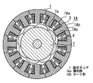
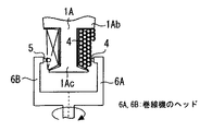
図1〜図6はこの発明の第1〜第4発明の一実施の形態を示す図で、図1はモータの集中巻固定子の巻線部分の拡大断面図、図2は集中巻固定子の横断面図、図3はコア部材(直線状)の平面図、図4は図1のIV部拡大図、図5はコア部材(円弧状)の平面図、図6は巻線方法説明図であり、図中同一符号は同一部分を示す。
【0013】
図において、1は磁性板が積層して構成されたリング状の固定子コアで、複数のコア部材1Aにより構成されている。コア部材1Aは薄肉部1Aaを有するヨーク部1Abを介して互いに屈曲可能に連結されており、各ヨーク部1Abにはそれぞれティース1Acが突出して形成されている。2はティース1Acの内側にテーピングされたプリプレグテープで、絶縁材3の固定用である。4は絶縁材3を介してティース1Acに巻回された電線である。
【0014】
5は、電線4の各巻線層の表面に巻回され電線4を固定するプリプレグテープ、6Aは供給される電線4をティース1Acに巻回する巻線機のヘッド、6Bは同じくプリプレグテープ5を電線4の表面に巻回する巻線機のヘッド、7は外周部に永久磁石7aが配置されたロータである。ここで、プリプレグテープ2,5は耐熱支持体に樹脂を含浸して半硬化状態に処理されたテープである。
【0015】
次に、上記のように構成された固定子コアに、例えば特開2000−324772号公報に示されるように、巻線機による巻線が施される。以下巻線工程について説明する。
まず、コア部材1Aは図3に示す直線状の状態から、薄肉部1Aaを屈曲させることにより、図5に示すように各ティース1Acが外側になるような円弧状に成形しておく。次に、ティース1Acの内側にプリプレグテープ2を巻線機のヘッドに6Bを使用して自動テーピングする。
【0016】
その後、絶縁材3をプリプレグテープ2の上から挿入する。そして、巻線機のヘッド6A,6Bを使用して、電線4とプリプレグテープ5を巻回する。このとき、プリプレグテープ5は、電線4の巻線直後に巻回されることにより、各層の電線4を覆うように所定回数巻回される。そして、巻線完了したコア部材1Aを,図2に示すように薄肉部1Aaを屈曲させて、今度はティース1Acが内側になるようなリング状に形成し、両側を例えば溶接等で固着することにより、固定子が形成される。
【0017】
その後、プリプレグテープ2,5の樹脂(図示しない)を硬化させるため、巻線完了した固定子を乾燥炉にセットして、加熱乾燥する。
このようにして、電線4の各巻回層ごとにプリプレグテープ5を巻回して電線4を結束し、加熱乾燥によりプリプレグテープ5の樹脂を硬化させるようにしたため、更に強固に電線4を固定し、電線4の移動によって生じる層間短絡等の事故防止機能の向上を図ることが可能となる。
【0018】
また、電線4及びプリプレグテープ5は共に自動巻きされており、更にワニス処理(含浸)工程を省略しているため、作業工程が大幅に短縮可能となる。
また、電線4の張力とテーピングの張力により絶縁材3を押圧することができるため、加熱乾燥時、絶縁材3をコア部材1Aに密着させることができ、スロット絶縁の機能を十分に果たすことが可能となる。
【0019】
【発明の効果】
以上説明したとおりこの発明の第1発明では、固定子コアの内側に突出するティースに巻回された電線の各層間にテープを介在させて電線を結束するようにしたので、強固に電線を固定して、層間短絡等の防止機能を向上することができる。
【0020】
また、第2発明では、テープをプリプレグテープとしたので、加熱乾燥による樹脂硬化により、更に強固に電線を固定することができるとともに、作業工程を大幅に短縮することができる。
【0021】
また、第3発明では、屈曲可能に連結されそれぞれ突出するティースを有する複数のコア部材をティースが外側となるような円弧状に形成し、このコア部材のティースに電線を巻線機により巻回し、巻回された電線上にプリプレグテープを巻線機により巻回した後、コア部材をティースが内側となるようなリング状に形成する各工程を備えたので、強固に電線を固定して、層間短絡等の防止機能を向上することができるとともに、ワニス処理工程を省略して作業工程を大幅に短縮することができる。
【0022】
また、第4発明では巻線工程を終了した固定子を加熱して、プリプレグテープを乾燥するようにしたので、プリプレグテープの樹脂が硬化して、電線の固定が強化されるとともに、作業工程を大幅に短縮することができる。
【図面の簡単な説明】
【図1】この発明の実施の形態1を示すモータの集中巻固定子の巻線部分の拡大断面図。
【図2】この発明の実施の形態1を示す集中巻固定子の横断面図。
【図3】この発明の実施の形態1を示すコア部材(直線状)の平面図。
【図4】この発明の実施の形態1を示す図1のIV部の拡大図。
【図5】この発明の実施の形態1を示すコア部材(円弧状)の平面図。
【図6】この発明の実施の形態1を示す巻線方法説明図。
【図7】従来の回転電機の固定子コイル部分の横断面図。
【符号の説明】
1 固定子コア、 1A コア部材、 1Aa 薄肉部、 1Ab ヨーク部、1Ac ティース、 2 プリプレグテープ、 3 絶縁材、 4 電線、 5 プリプレグテープ、 6A,6B 巻線機のヘッド。[0001]
TECHNICAL FIELD OF THE INVENTION
The present invention relates to a stator used for a rotating electric machine, particularly a permanent magnet motor, and a method for manufacturing the same.
[0002]
[Prior art]
A concentrated winding coil is used for teeth of a stator of a permanent magnet motor in which a permanent magnet is arranged on a rotor. The concentrated winding coil refers to a coil in which an electric wire is wound around one tooth, and is disclosed in, for example, Japanese Patent Application Laid-Open No. 9-308142.
In this type of coil, the electric wire needs to be securely fixed because the electric wire may move due to electromagnetic vibration or the like, causing an interlayer short circuit or breaking the slot insulation and causing a ground fault. ]
Conventionally, in order to fix the winding of the stator coil, means for vacuum impregnation or immersion impregnation after winding has been used. In the case of vacuum impregnation, the varnish permeates the most regardless of the shape of the work, and a highly reliable coil can be obtained. In addition, immersion impregnation has the advantage that the impregnation equipment can be simplified because expensive equipment is not required as much as vacuum impregnation, but varnish hardly penetrates when the coil diameter is small and the number of turns is large.
[0004]
As a means for improving these impregnation means, many coils using self-fusing electric wires have been used. According to this means, since only a drying step after the winding does not require any care, the processing time is greatly reduced.
FIG. 7 is a cross-sectional view of a stator coil portion disclosed in, for example, JP-A-5-68359, in which a slot insulating material 9 made of a self-fusing thin leaf material and a self-fusing electric wire 10 are wound a plurality of times. A rotating stator coil is shown.
[0005]
That is, the slot insulating material 9 is inserted in advance along the inner wall surface of the slot, and the self-fusing electric wire 10 is wound inside the slot insulating material 9 a plurality of times. After inserting the wedge 11 made of a conductive thin leaf material, a heat treatment is performed.
[0006]
[Problems to be solved by the invention]
In the above-described conventional rotating electric machine stator, since the self-fusing electric wire 10 is wound and then dried, a space is easily generated in a straight portion of the coil where the tension of the winding is not applied. However, there is a problem that the electric wire moves during operation for a long period of time, and that portion may be a starting point to cause fatigue rupture or an accident such as an interlayer short circuit.
[0007]
SUMMARY OF THE INVENTION The present invention has been made to solve the above problems, and an object of the present invention is to provide a stator for a rotating electric machine which can securely fix an electric wire and can work efficiently, and a method of manufacturing the same.
[0008]
[Means for Solving the Problems]
The stator of the rotating electric machine according to the first aspect of the present invention is a stator in which a plurality of teeth protrude inside a ring-shaped stator core and a plurality of layers of wires are wound around the teeth. And a tape that is interposed between the layers and binds the electric wires.
[0009]
Further, the stator of the rotating electric machine according to the second invention is the stator of the first invention, wherein the tape is a prepreg tape.
[0010]
The method for manufacturing a stator of a rotating electric machine according to a third aspect of the present invention includes a step of forming a plurality of core members having teeth protruding and connected to each other in an arc shape such that the teeth are on the outside, A step of winding an electric wire on a tooth of the core member formed as described above by a winding machine, and a step of winding a prepreg tape on the wound electric wire by the winding machine simultaneously with this step, A step of forming the core member in a ring shape such that the teeth are inside, following the step.
[0011]
The method for manufacturing a stator for a rotating electric machine according to a fourth aspect of the present invention includes a step of heating the stator having completed the steps of the third aspect of the invention and drying the prepreg tape.
[0012]
BEST MODE FOR CARRYING OUT THE INVENTION
Embodiment 1 FIG.
1 to 6 show one embodiment of the first to fourth inventions of the present invention. FIG. 1 is an enlarged sectional view of a winding portion of a concentrated winding stator of a motor, and FIG. 2 is a concentrated winding stator. , FIG. 3 is a plan view of a core member (straight line), FIG. 4 is an enlarged view of an IV section in FIG. 1, FIG. 5 is a plan view of a core member (arc shape), and FIG. In the drawings, the same reference numerals indicate the same parts.
[0013]
In the figure, reference numeral 1 denotes a ring-shaped stator core formed by laminating magnetic plates, and is constituted by a plurality of core members 1A. The core member 1A is flexibly connected to each other via a yoke 1Ab having a thin portion 1Aa, and each yoke 1Ab is formed with a tooth 1Ac protruding therefrom. Reference numeral 2 denotes a prepreg tape taped inside the teeth 1Ac for fixing the insulating material 3. Reference numeral 4 denotes an electric wire wound around the teeth 1Ac via the insulating material 3.
[0014]
5 is a prepreg tape wound around the surface of each winding layer of the electric wire 4 to fix the electric wire 4, 6A is a head of a winding machine for winding the supplied electric wire 4 around the teeth 1Ac, and 6B is a prepreg tape 5 similarly. A head 7 of the winding machine wound around the surface of the electric wire 4 is a rotor having a permanent magnet 7a disposed on an outer peripheral portion. Here, the prepreg tapes 2 and 5 are tapes in which a heat-resistant support is impregnated with a resin and processed into a semi-cured state.
[0015]
Next, the stator core configured as described above is subjected to winding by a winding machine as shown in, for example, JP-A-2000-324772. Hereinafter, the winding step will be described.
First, the core member 1A is formed into an arc shape such that each tooth 1Ac is outside as shown in FIG. 5 by bending the thin portion 1Aa from the linear state shown in FIG. Next, the prepreg tape 2 is automatically taped inside the teeth 1Ac by using 6B for the head of the winding machine.
[0016]
After that, the insulating material 3 is inserted from above the prepreg tape 2. Then, the electric wire 4 and the prepreg tape 5 are wound using the heads 6A and 6B of the winding machine. At this time, the prepreg tape 5 is wound immediately after the electric wire 4 is wound, so that the prepreg tape 5 is wound a predetermined number of times so as to cover the electric wires 4 in each layer. Then, the wound core member 1A is formed into a ring shape in which the thin portion 1Aa is bent as shown in FIG. 2 and the teeth 1Ac are on the inside, and both sides are fixed by, for example, welding. Thus, a stator is formed.
[0017]
Then, in order to harden the resin (not shown) of the prepreg tapes 2 and 5, the stator after the completion of the winding is set in a drying furnace and heated and dried.
In this way, the prepreg tape 5 is wound for each winding layer of the electric wire 4 to bind the electric wire 4, and the resin of the prepreg tape 5 is hardened by heating and drying, so that the electric wire 4 is further firmly fixed. It is possible to improve the function of preventing an accident such as an interlayer short circuit caused by the movement of the electric wire 4.
[0018]
In addition, since the electric wire 4 and the prepreg tape 5 are both automatically wound and the varnish treatment (impregnation) step is omitted, the working steps can be greatly reduced.
Further, since the insulating material 3 can be pressed by the tension of the electric wire 4 and the tension of the taping, the insulating material 3 can be brought into close contact with the core member 1A during heating and drying, and the function of slot insulation can be sufficiently performed. It becomes possible.
[0019]
【The invention's effect】
As described above, in the first aspect of the present invention, the wires are bound by interposing the tape between the layers of the wires wound around the teeth protruding inside the stator core, so that the wires are firmly fixed. Thus, the function of preventing an interlayer short circuit or the like can be improved.
[0020]
Further, in the second invention, since the tape is a prepreg tape, the electric wire can be more firmly fixed by resin curing by heating and drying, and the operation process can be significantly shortened.
[0021]
Further, in the third invention, a plurality of core members having bendable and connected protruding teeth are formed in an arc shape such that the teeth are outside, and an electric wire is wound around the teeth of the core member by a winding machine. After winding the prepreg tape on the wound electric wire by a winding machine, each step of forming the core member in a ring shape such that the teeth are inside is provided, so that the electric wire is firmly fixed, The function of preventing an interlayer short circuit or the like can be improved, and the varnish treatment step can be omitted to greatly reduce the work steps.
[0022]
Further, in the fourth invention, the stator after the winding step is heated to dry the prepreg tape, so that the resin of the prepreg tape is hardened, and the fixing of the electric wire is strengthened, and the work process is reduced. It can be greatly reduced.
[Brief description of the drawings]
FIG. 1 is an enlarged sectional view of a winding portion of a concentrated winding stator of a motor according to a first embodiment of the present invention.
FIG. 2 is a cross-sectional view of the concentrated winding stator according to the first embodiment of the present invention.
FIG. 3 is a plan view of a core member (linear) showing the first embodiment of the present invention.
FIG. 4 is an enlarged view of a portion IV in FIG. 1 showing the first embodiment of the present invention.
FIG. 5 is a plan view of a core member (arc shape) showing the first embodiment of the present invention.
FIG. 6 is an explanatory view of a winding method according to the first embodiment of the present invention.
FIG. 7 is a cross-sectional view of a stator coil portion of a conventional rotating electric machine.
[Explanation of symbols]
DESCRIPTION OF SYMBOLS 1 Stator core, 1A core member, 1Aa thin part, 1Ab yoke part, 1Ac teeth, 2 prepreg tape, 3 insulating material, 4 electric wires, 5 prepreg tape, 6A, 6B Winding machine head.