JP2004038204A - Liquid crystal display and electronic equipment - Google Patents
Liquid crystal display and electronic equipment Download PDFInfo
- Publication number
- JP2004038204A JP2004038204A JP2003345845A JP2003345845A JP2004038204A JP 2004038204 A JP2004038204 A JP 2004038204A JP 2003345845 A JP2003345845 A JP 2003345845A JP 2003345845 A JP2003345845 A JP 2003345845A JP 2004038204 A JP2004038204 A JP 2004038204A
- Authority
- JP
- Japan
- Prior art keywords
- liquid crystal
- polarizing layer
- crystal display
- display device
- light
- Prior art date
- Legal status (The legal status is an assumption and is not a legal conclusion. Google has not performed a legal analysis and makes no representation as to the accuracy of the status listed.)
- Withdrawn
Links
Images


Abstract
Description
本発明は、液晶表示装置および電子機器に係り、特に透過モード時にも十分な明るさの表示が可能な半透過反射型の液晶表示装置の構成に関するものである。 The present invention relates to a liquid crystal display device and an electronic apparatus, and more particularly to a configuration of a transflective liquid crystal display device capable of displaying sufficient brightness even in a transmission mode.
反射型液晶表示装置はバックライト等の光源を持たないために消費電力が小さく、従来から種々の携帯電子機器や装置の付属的な表示部等に多用されている。
ところが、自然光や照明光などの外光を利用して表示するため、暗い場所では表示を視認することが難しいという問題があった。そこで、明るい場所では通常の反射型液晶表示装置と同様に外光を利用するが、暗い場所では内部の光源により表示を視認可能にした形態の液晶表示装置が提案されている。つまり、この液晶表示装置は反射型と透過型を兼ね備えた表示方式を採用しており、周囲の明るさに応じて反射モード、透過モードのいずれかの表示方式に切り替えることにより消費電力を低減しつつ周囲が暗い場合でも明瞭な表示が行うことが出来るようにしたものである。以下、本明細書ではこの種の液晶表示装置のことを「半透過反射型液晶表示装置」という。
Reflection type liquid crystal display devices have low power consumption because they do not have a light source such as a backlight, and have been widely used in various portable electronic devices and display units attached to devices.
However, since display is performed using external light such as natural light or illumination light, there is a problem that it is difficult to visually recognize the display in a dark place. Therefore, there has been proposed a liquid crystal display device in which external light is used in a bright place as in a normal reflective liquid crystal display device, but in a dark place, the display can be visually recognized by an internal light source. In other words, this liquid crystal display device employs a display method having both a reflective type and a transmissive type, and reduces power consumption by switching to a reflective mode or a transmissive mode according to the surrounding brightness. In addition, even when the surroundings are dark, clear display can be performed. Hereinafter, in this specification, this type of liquid crystal display device is referred to as a “semi-transmissive reflective liquid crystal display device”.
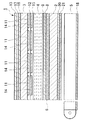
半透過反射型液晶表示装置の形態として、アルミニウム等の金属膜に光透過用のスリットを形成した反射膜を下基板内面に備えた液晶表示装置が提案されている。これは、金属膜を下基板内面側に設けることにより、下基板の厚みによるパララックスの影響を防ぎ、特にカラーフィルタを用いた構造では混色を防いでいる。図9はパッシブマトリクス方式の半透過反射型液晶表示装置の一例を示す部分断面図である。この液晶表示装置100では、一対の透明な上基板102、下基板101間に液晶103が挟持されており、下基板101上に反射膜104、絶縁膜106が積層され、その上にインジウム錫酸化物(Indium Tin Oxide, 以下、ITOと略記する。)等の透明導電膜からなるストライプ状の走査電極108が形成され、走査電極108を覆うように配向膜107が形成されている。一方、上基板102上には、カラーフィルタ109が形成され、その上に平坦化膜111が積層され、この平坦化膜111上にITO等の透明導電膜からなる信号電極112が走査電極108と直交する方向にストライプ状に形成されており、この信号電極112を覆うように配向膜113が形成されている。反射膜104はアルミニウムなどの金属膜で形成されており、この反射膜104には各画素毎に光透過用のスリット110が形成されている。このスリット110により下基板101側から入射する光を透過させることで、反射膜104は半透過反射膜として機能する。また、上基板102の外側には上基板102側から順に前方散乱板118、位相差板119、上偏光板114が配置され、下基板101の外側には1/4波長板115と下偏光板116が設けられている。また、バックライト117が下基板101の下面側に配置されている。
(4) As a form of the transflective liquid crystal display device, there has been proposed a liquid crystal display device having a reflective film in which a slit for transmitting light is formed in a metal film such as aluminum on the inner surface of a lower substrate. This is because by providing a metal film on the inner surface side of the lower substrate, the influence of parallax due to the thickness of the lower substrate is prevented, and particularly in a structure using a color filter, color mixing is prevented. FIG. 9 is a partial sectional view showing an example of a transflective liquid crystal display device of a passive matrix system. In this liquid
上記構成の液晶表示装置100を明るい場所で反射モードで使用する際には上基板102の上方から入射した外光が液晶103を透過して反射膜104の表面で反射された後、再度液晶103を透過し、上基板102側に出射される。暗い場所で透過モードで使用する際には下基板101の下方に設置したバックライト117から出射される光がスリット110の部分で反射膜104を透過し、その後、液晶103を透過して上基板102側に出射される。これらの光が各モードでの表示に寄与する。
When the liquid
上記液晶表示装置100によれば、外光の有無に関わらず表示の視認が可能であるものの、反射モード時に比べて透過モード時の明るさが不足するという問題があった。これは、主に透過モード時の表示に寄与し得る光量が、反射膜104に設けたスリット110を通過した光量のみであることと、下基板101の外面側に設けられた1/4波長板115および偏光板116に起因する光の損失によるものである。
According to the liquid
図9に示す液晶表示装置100において、透過モードでの表示を行う場合には、バックライト117から出射された光が、下基板101の外側から液晶表示ユニットに入射し、この光のうちスリット110を通過した光が表示に寄与する光となる。ここで、液晶表示装置100において暗表示を行うためには、スリット110から上基板102へ向かう光が円偏光である必要がある。従って、バックライト117から出射されてスリット110を通過した光も円偏光となっている必要があるので、下偏光板116を透過して直線偏光に変換された光を円偏光に変換するための1/4波長板115が必要となる。
In the case of performing display in the transmission mode in the liquid
次に、バックライト117から出射された光のうち、スリット110を通過しない光に着目すると、バックライト117から出射され、下偏光板116を通過して紙面に平行な直線偏光とされた後、1/4波長板115を通過して円偏光とされ、反射膜104に到達する。この光がスリット110に入射せず反射膜104の下基板101側の面で反射されると、反射膜104に入射する円偏光とは逆回りの円偏光となり、この光が再び1/4波長板115を通過すると紙面に垂直な直線偏光に変換される。従って、この光は紙面に平行な透過軸を有する下偏光板116によって吸収される。つまり、バックライト117から出射された光のうち、スリット110を通過せずに反射膜104の裏面側で反射された光は、下基板101の下偏光板116によってそのほぼ全てが吸収されてしまう。
Next, when attention is paid to light that does not pass through the
さらに、図9に示す液晶表示装置において透過モードの明表示を行う場合に着目すると、スリット110を通過して液晶103に入射した光は、液晶103による作用を受けずに上基板102の上偏光板114を通過して液晶表示装置の上方に出射されるが、スリット110から上基板102へ向かう光は1/4波長板115によって円偏光になっているので、紙面に平行な透過軸を有する上偏光板114を通過する際にその約半分が上偏光板114に吸収されてしまう。
Further, focusing on the case where bright display in the transmission mode is performed in the liquid crystal display device shown in FIG. 9, light incident on the
以上の理由から、上記液晶表示装置100においては、透過モード時の表示を明るくすることができなかった。そこで、上記のような問題を解決するために、図10に示す構成の液晶表示装置が提案されている。図10に示す液晶表示装置200は、一対の透明な下基板201と上基板202間に液晶203が挟持されており、下基板201上に反射偏光層204、絶縁層206が積層され、その上にITO等の透明導電膜からなるストライプ状の走査電極208が形成され、走査電極208を覆うように配向膜207が形成されている。一方、上基板202の内面側には、カラーフィルタ209が形成され、その上に平坦化膜211が積層され、この平坦化膜211上にITO等の透明導電膜からなる信号電極212が走査電極208と直交する方向にストライプ状に形成されており、この信号電極212を覆うように配向膜213が形成されている。反射偏光層204は、アルミニウムなどの金属膜に、幅50nm程度の微細な開口部をスリット状に150nm〜400nmピッチで形成したものである。この反射偏光層204に入射した光は、スリット状の開口部に平行な偏光が反射され、前記開口部に垂直な偏光は透過するようになっている。また、上基板202の外側には上基板202側から順に前方散乱板218、位相差板219、上偏光板214が配置されている。また、バックライト217が下基板201の下面側に配置されている。
For the above reasons, in the liquid
上記構成の液晶表示装置200においては、透過モードでは図9に示す液晶表示装置100とは異なり、上偏光板214に入射する光は円偏光ではなく直線偏光であるため、上記の液晶表示装置100に比して透過モード時の表示を明るくすることが可能である。また、反射偏光層204を透過せずに反射された光は、バックライト217へ戻され、反射偏光層204とバックライト217との間で反射を繰り返すうち、その偏光状態が変化して反射偏光層204を透過できるようになるので、上記液晶表示装置100よりもバックライト217の光を有効に利用することができる。
In the liquid
しかしながら、上記の構成の液晶表示装置200は、透過モードで使用する際に、液晶表示装置200に外光が入射すると、液晶表示装置200のコントラストが著しく低下し、この外光の強度によっては表示が視認できなくなる場合があった。本発明者は、この問題について詳細な検討を行い、本発明を完成するに到った。尚、この検証内容については、後述の(課題を解決するための手段)において詳細に説明する。
However, when the liquid
従って本発明の目的の一つは、反射モード、透過モードを備える半透過反射型の液晶表示装置において、透過モード時の表示の明るさを向上させ、視認性に優れる半透過反射型の液晶表示装置を提供することにある。
また、本発明の目的の一つは、上記の視認性に優れた半透過反射型の液晶表示装置を備えた電子機器を提供することにある。
Accordingly, an object of the present invention is to provide a transflective liquid crystal display device having a reflective mode and a transmissive mode, in which the display brightness in the transmissive mode is improved and the transflective liquid crystal display with excellent visibility is provided. It is to provide a device.
Another object of the present invention is to provide an electronic device provided with a transflective liquid crystal display device having excellent visibility as described above.
上記の目的を達成するために、本発明の液晶表示装置は、互いに対向する上基板と下基板との間に液晶が挟持され、該液晶の上下に上偏光層と、下反射偏光層とを備えた液晶パネルと、前記液晶パネルの外面側に設けられた照明装置とを備え、透過モードと反射モードの切替により表示を行う半透過反射型の液晶表示装置であって、前記下反射偏光層が、透過軸と該透過軸に直交する反射軸を有し、入射する光の前記反射軸に平行な成分の一部を反射し、一部を透過する半透過反射型の反射偏光層であり、前記下反射偏光層の下側に、下偏光層が設けられたことを特徴とする。 In order to achieve the above object, in the liquid crystal display device of the present invention, a liquid crystal is sandwiched between an upper substrate and a lower substrate facing each other, an upper polarizing layer above and below the liquid crystal, and a lower reflective polarizing layer. A transflective liquid crystal display device, comprising: a liquid crystal panel provided with an illuminating device provided on an outer surface side of the liquid crystal panel, and performing display by switching between a transmission mode and a reflection mode, wherein the lower reflective polarizing layer Is a transflective reflective polarizing layer that has a transmission axis and a reflection axis orthogonal to the transmission axis, reflects a part of a component of incident light parallel to the reflection axis, and transmits a part. A lower polarizing layer is provided below the lower reflective polarizing layer.
本発明の係る構成によれば、透過モード時の表示の明るさを格段に向上させることができるとともに、図10に示す液晶表示装置200の問題点も解決し、透過モード時に外光が入射してもコントラストが低下しないようにすることができる。これらの効果について、図3および図4を参照して以下に詳細に説明する。
According to the configuration of the present invention, the brightness of the display in the transmission mode can be remarkably improved, and the problem of the liquid
図3は、本発明の液晶表示装置の動作原理を説明するための説明図であり、図3(a)は透過モード、図3(b)は反射モードの光の経路を示している。これらの図には、本発明の液晶表示装置の構成要素のうち、説明に必要な構成要素のみを示しており、液晶53を挟んで上下に上偏光板54と下反射偏光層51が設けられ、この下反射偏光層51の外側に下基板50が配置され、下基板50の外面側に下偏光層55が形成されている。下偏光層55の外側(図示下面側)には、照明装置58が設けられ、この照明装置58の外面側に反射板59が設けられている。
FIG. 3 is an explanatory view for explaining the operation principle of the liquid crystal display device of the present invention. FIG. 3 (a) shows a transmission mode light path, and FIG. 3 (b) shows a reflection mode light path. In these drawings, among the components of the liquid crystal display device of the present invention, only the components necessary for the description are shown. An upper
前記上偏光板54は紙面に垂直な方向の透過軸を有しており、下偏光層55は、紙面に平行な透過軸を有している。また、上記下反射偏光層51は、半透過反射型の反射偏光層とされており、紙面に垂直な方向の透過軸とこの透過軸と直交する反射軸を有している。そして、透過軸に平行な光はほとんど全て透過させるが、反射軸に平行な光の一部は反射させ、一部は透過させるようになっている。すなわち、下反射偏光層51は、その反射軸に平行な光に対しての半透過反射型とされている。
The upper
以下、図3(a)に示す透過モードで表示を行う場合について説明する。
本発明の液晶表示装置では、透過モードの表示を照明装置58から出射された光を利用して行うようになっている。照明装置58から出射された光は、紙面に平行な透過軸を有する下偏光層55により紙面に平行な偏光へ変換され、その後下基板50を透過して下反射偏光層51に入射する。この下反射偏光層51は、上述のように紙面に垂直な透過軸を有しており、下偏光層55により紙面に平行な偏光とされた光の一部は反射されて照明装置58側へ戻される反射光61とされ、一部は透過されて液晶53に入射する透過光60とされる。
Hereinafter, a case where display is performed in the transmission mode shown in FIG. 3A will be described.
In the liquid crystal display device of the present invention, transmission mode display is performed using light emitted from the
次いで、液晶53に入射した透過光60は、液晶53に電圧が印加された状態(オン状態)であれば、前記液晶53に入射した光は液晶53による作用をほとんど受けずに上偏光板54に到達し、紙面に垂直な透過軸を有する上偏光板54に吸収され、画素が暗表示される。一方、液晶53に電圧が印加されない状態(オフ状態)であれば、前記液晶53に入射した透過光60は、液晶53の旋光作用により紙面に垂直な偏光へと変換され、上偏光板54に到達する。そして、上偏光板54の透過軸と平行な偏光であるこの光は、上偏光板54を透過し、画素が明表示されるようになっている。
Next, when the transmitted light 60 incident on the
ここで、下反射偏光層51の裏面側(下基板50側)で反射された反射光60に着目すると、この反射光60は、下基板50、下偏光層55を透過して照明装置58へと戻り、照明装置58外面側の反射板59により反射され、再び下偏光層55へ向かう光として再利用される。そして、この光は再び下反射偏光層51へ到達し、一部は透過されて液晶53に入射し、一部は反射されて照明装置58側へ戻される。このように下反射偏光層51で反射された光は、下反射偏光層51と反射板59の間で反射を繰り返すうちに下反射偏光層51を透過し、表示に寄与する光として利用される。従って、本発明の液晶表示装置においては、照明装置58から出射された光のうち、下偏光層55を透過した光を最大限に利用することができ、明るい表示を得ることができる。
Here, focusing on the reflected light 60 reflected on the back surface side (the
次に、図3(b)に示す反射モードで表示を行う場合について説明する。
図3(b)に示すように、上偏光板54の上方から入射した光は、まず、紙面に垂直な透過軸を有する上偏光板54により紙面に垂直な偏光に変換されて液晶53に入射する。次いで、液晶がオン状態であれば、この入射光は液晶53による作用をほとんど受けずに下反射偏光層51に到達する。そして下反射偏光層51は、紙面に垂直な透過軸と、紙面に平行な反射軸を有しているので、この下反射偏光層51に到達した光は下反射偏光層51を透過する。その後、下基板50を透過して、紙面に平行な透過軸を有する下偏光層55により吸収され、画素が暗表示される。
Next, a case where display is performed in the reflection mode shown in FIG. 3B will be described.
As shown in FIG. 3B, light incident from above the upper
一方、液晶53がオフ状態であれば、液晶53に入射した光は、液晶53の旋光作用により紙面に平行な偏光へ変換され、下反射偏光層51へ到達する。そして、紙面に平行な反射軸を有する下反射偏光層51によりその一部が反射されて反射光63とされ、一部は透過されて透過光62となる。反射光63は、液晶53の旋光作用により再び紙面に垂直な偏光へ変換されて上偏光板54を透過して、画素が明表示される。また、下反射偏光層51を透過した透過光62は、下基板50及び下偏光層55を透過して照明装置58へ出射される。照明装置58には反射板59が設けられているので、この透過光62の一部は反射板59で反射されて下基板50側へ戻るが、この光が液層53に入射すると、明表示された画素はより明るくなる。
On the other hand, when the
このように、本発明の液晶表示装置においては、図9に示す液晶表示装置100のように、下基板101の外側に1/4波長板115を設けなくとも表示を行うことができる。従って、直線偏光から円偏光、または円偏光から直線偏光への変換が生じないので、これらの変換に伴う光の損失がない。これにより、明るい表示を得ることができ、特に透過モード時の明るさを大幅に向上させることができる。
As described above, in the liquid crystal display device of the present invention, as in the liquid
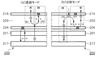
次に、図10に示す従来の構成の液晶表示装置200の動作について図4を参照して説明する。
図4は、上記液晶表示装置200の動作を説明するための説明図であり、図10に示す構成要素のうち、説明に必要な構成要素のみを図示したものである。すなわち、液晶203と、その上下に配された上偏光板214、反射偏光層204と、下基板201、およびこの下基板201の外面側に配されたバックライト217のみが図示されている。
Next, the operation of the conventional liquid
FIG. 4 is an explanatory diagram for explaining the operation of the liquid
まず、図4(a)に示す透過モードについて説明する。
液晶表示装置200において、バックライト(照明装置)217から出射された光は、下基板201を透過して反射偏光層204に到達する。この反射偏光層204は、紙面に垂直な透過軸と、紙面に平行な反射軸を有するので、反射偏光層204に到達した光の一部は、紙面に垂直な偏光に変換されて液晶203に入射する。そして、液晶203がオン状態であれば、液晶203による作用をほとんど受けずに上偏光板214に到達し、紙面に垂直な透過軸を有するこの上偏光板214を透過する。このようにして画素が明表示される。一方、液晶203がオフ状態であれば、液晶203に入射した光は液晶203の旋光作用により紙面に平行な偏光へ変換されて上偏光板54に到達し、紙面に垂直な透過軸を有する上偏光板54に吸収される。このようにして、画素が暗表示されるようになっている。
First, the transmission mode shown in FIG.
In the liquid
次に、図4(b)に示す反射モードについて説明する。
図4(b)に示すように、上偏光板214の上方から入射した光は、紙面に垂直な透過軸を有する上偏光板214により紙面に垂直な偏光へ変換されて液晶203に入射する。そして、液晶203がオン状態であれば、この入射した光はそのまま反射偏光板204に到達し、紙面に垂直な透過軸を有する反射偏光板204を透過した後、基板201を透過してバックライト217側へ出射される。このようにして、画素が暗表示されるようになっている。一方、液晶203がオフ状態であれば、液晶203に入射した光は液晶203の旋光作用により紙面に平行な偏光へ変換され、反射偏光板204へ到達する。ここで、反射偏光板204は紙面に平行な反射軸を有するので、この光は反射され、再び液晶203へ入射する。そして、液晶203の旋光作用により紙面に垂直な偏光に変換されて、上偏光板214を透過する。このようにして画素が明表示されるようになっている。
Next, the reflection mode shown in FIG. 4B will be described.
As shown in FIG. 4B, light incident from above the upper
上記液晶表示装置200における、透過モード時に液晶表示装置200に外光が入射するとコントラストが大きく低下するという問題は、透過モード時と反射モード時において、明表示、暗表示に対応する液晶203のオン/オフ状態が異なっていることによるものである。つまり、画素を暗表示させる場合において、透過モードでは液晶はオフ状態となっているが、反射モードでは、液晶はオン状態となっている。このために、例えば透過モードで使用している状態において、液晶表示装置200に外光が入射すると、暗表示の画素(液晶に電圧が印加されていない画素)に入射した外光が反射偏光層204の上面で反射され、上基板201を透過して液晶表示装置200の上方に出射される。このために暗表示されるべき画素が明表示となり、結果としてコントラストが低下し、場合によっては表示を視認できなくなる。
In the liquid
これに対して、本発明の液晶表示装置においては、図3(a)、(b)に示すように、透過モードの明表示と、反射モードの明表示の状態では、いずれも液晶53はオフ状態とされており、逆に暗表示では両モードとも液晶53はオン状態とされている。従って、透過モードで使用している場合に、外光が入射しても、暗表示の画素では液晶53がオン状態とされているので、図3(b)に示すように、液晶53に入射した外光は下基板50の外面側の下偏光層55に吸収され、上偏光板54側へ戻らないようになっている。従って、上記の液晶表示装置200のようなコントラストの低下が起こらず、良好な視認性を得ることができる。
On the other hand, in the liquid crystal display device of the present invention, as shown in FIGS. 3A and 3B, the
さらに、本発明の液晶表示装置においては、図3に示すように下基板50の外面側に下偏光層55が設けられていることにより、図4に示す液晶表示装置200よりもコントラストを高めることができる。これは、図4(b)に示す液晶表示装置200では、外光は上偏光板214、液晶203、反射偏光層203を透過した後、バックライト217側へ出射されるようになっているのに対して、本発明の液晶表示装置では、暗表示の画素に入射した外光は、上偏光板54、液晶53、下反射偏光層51を透過した後、下偏光層55により吸収されるためである。つまり、図4(b)に示す液晶表示装置200では、バックライト217側へ出射された光が、バックライト217の外面側に設けられた反射板(図示せず)により反射されて液晶203側へ向かう光となる場合があり、これにより暗表示が明るくなってコントラストが低下する場合があるが、本発明の液晶表示装置では、下偏光板55により吸収されて液晶53側へ再び戻ることはないからである。
Further, in the liquid crystal display device of the present invention, since the lower
このように、本発明の液晶表示装置によれば、従来の半透過反射型の液晶表示装置に比して、照明装置から出射される光を有効に利用することができるので、透過モードにおける表示の明るさを格段に向上させることができる。また、明暗表示に対応する液晶のオン/オフ状態が、透過モードと反射モードで同じくされているので、透過モード時に外光が入射した場合も、コントラストの低下が起こらず、鮮明な表示が得られる。さらに、反射モードの暗表示において、液晶を透過した光を下偏光層で吸収する構造としたことにより、暗表示をより暗くすることができるので、反射モード時のコントラストも向上させることができる。 As described above, according to the liquid crystal display device of the present invention, the light emitted from the illumination device can be used more effectively as compared with the conventional transflective liquid crystal display device. Can be remarkably improved. Further, since the on / off state of the liquid crystal corresponding to the light and dark display is the same in the transmission mode and the reflection mode, even if external light enters in the transmission mode, the contrast does not decrease and a clear display is obtained. Can be Further, in the dark display in the reflection mode, by adopting a structure in which the light transmitted through the liquid crystal is absorbed by the lower polarizing layer, the dark display can be made darker, so that the contrast in the reflection mode can be improved.
次に、本発明の液晶表示装置においては、前記下反射偏光層の、反射軸に平行な光の透過率が、20%以上70%以下とされることが好ましく、前記下反射偏光層の、反射軸に平行な光の透過率が、30%以上50%以下とされることがより好ましい。 Next, in the liquid crystal display device of the present invention, it is preferable that the transmittance of light parallel to the reflection axis of the lower reflective polarizing layer is 20% or more and 70% or less. More preferably, the transmittance of light parallel to the reflection axis is 30% or more and 50% or less.
下反射偏光層の反射率を前記の範囲とすることで、透過モードと反射モードのいずれでも明るい表示を得ることができ、視認性に優れた液晶表示装置が得られる。
前記透過率が20%未満であると、照明装置から液晶へ入射する光量が少なすぎるために、透過モード時の表示の明るさが不足し、70%を越えると、反射モード時に下反射偏光層で反射されて表示に利用される光量が不足する。また、前記透過率を30%以上50%以下の範囲とすることで、透過モードと反射モードの明るさのバランスを良好なものとし、より視認性に優れる液晶表示装置とすることができる。
By setting the reflectance of the lower reflective polarizing layer within the above range, a bright display can be obtained in both the transmission mode and the reflection mode, and a liquid crystal display device with excellent visibility can be obtained.
If the transmittance is less than 20%, the amount of light incident on the liquid crystal from the lighting device is too small, so that the display brightness in the transmission mode is insufficient. If it exceeds 70%, the lower reflective polarizing layer is in the reflection mode. And the amount of light used for display is insufficient. Further, by setting the transmittance in the range of 30% or more and 50% or less, the balance between the brightness in the transmission mode and the brightness in the reflection mode can be improved, and a liquid crystal display device with more excellent visibility can be obtained.
次に、本発明の液晶表示装置においては、前記下反射偏光層の透過軸と、下偏光層の透過軸との成す角度が、60度以上120度以下とされることが好ましい。 Next, in the liquid crystal display device of the present invention, it is preferable that the angle formed by the transmission axis of the lower reflective polarizing layer and the transmission axis of the lower polarizing layer is not less than 60 degrees and not more than 120 degrees.
図3(b)に示す反射モードにおいて、暗表示を行う場合には、液晶表示装置に入射した外光は、最終的に下偏光層55に吸収されるようになっているが、下反射偏光層51を透過した光のうち、下偏光層55の透過軸に平行な成分は、下偏光層55を透過し、照明装置58側へ出射される。この光が反射板59で反射されて液晶53側へ戻ると、暗表示が明るくなりコントラストが低下する。従って、前記下偏光層55の透過軸と下反射偏光層51の透過軸とが成す角度は、90°(両者が直交)であることが最も望ましいのは勿論であるが、両者の透過軸が成す角度が±30°以内であれば、実用的に用いることができる。両者の透過軸が成す角度が前記範囲を越えると、下偏光層55を透過する光量が多くなり、液晶表示装置のコントラストが低下する。
In the reflection mode shown in FIG. 3B, when dark display is performed, external light incident on the liquid crystal display device is finally absorbed by the lower
次に、本発明の液晶表示装置は、前記下偏光層の外面側に、反射偏光板を備えた構成とすることもできる。このような構成とすることにより、照明装置から出射された光を、より効率よく表示に利用することができ、透過モード時の表示をより明るくすることができる。この構成について、図5を参照して以下に詳細に説明する。 Next, the liquid crystal display device of the present invention may have a configuration in which a reflective polarizing plate is provided on the outer surface side of the lower polarizing layer. With such a configuration, light emitted from the lighting device can be more efficiently used for display, and display in the transmission mode can be made brighter. This configuration will be described in detail below with reference to FIG.
図5は、上記の構成を採用した本発明に係る液晶表示装置の要部を示す説明図である。この図に示す液晶表示装置が、図3に示す液晶表示装置と異なる点は、下基板の外面側に反射偏光板が設けられている点のみである。従って、以下では、図5に示す反射偏光板57の作用についてのみ詳細に説明する。また、図5に示す構成要素のうち、図3に示す構成要素と同一のものには、同一の符号を付してその説明は省略する。
FIG. 5 is an explanatory view showing a main part of the liquid crystal display device according to the present invention employing the above configuration. The liquid crystal display device shown in this figure differs from the liquid crystal display device shown in FIG. 3 only in that a reflective polarizer is provided on the outer surface side of the lower substrate. Therefore, only the operation of the reflective
図5に示す反射偏光板57は、紙面に平行な透過軸と、紙面に垂直な反射軸を有する反射偏光板である。この液晶表示装置における表示原理は、図3(a)に示す液晶表示装置の透過モードとほぼ同様であり、照明装置58から出射された光は、紙面に平行な透過軸を有する反射偏光板57により、紙面に平行な偏光成分のみが透過され、下偏光層55および下基板50を透過する。そして、この光の一部が下反射偏光層を透過して液晶53に入射する。ここで、液晶53がオン状態であれば、入射した光はそのまま上偏光板54に到達し、紙面と垂直な透過軸を有する上偏光板に吸収され、画素が暗表示されるようになっている。あるいは液晶53がオフ状態であれば、入射した光は液晶53の旋光作用により紙面に垂直な偏光へと変換され、上偏光板54を透過する。このようにして画素が明表示されるようになっている。
反射 The reflective
図5に示す液晶表示装置は、反射偏光板57が設けられていることにより、図3に示す液晶表示装置よりもさらに明るい表示を得ることができる。これは、図3に示す液晶表示装置では、照明装置58から出射された光の約半分が、下偏光層55により吸収されるのに対し、図5に示す構成の液晶表示装置では、下偏光層55による光の吸収が起こらないためである。
The liquid crystal display device shown in FIG. 5 can provide a brighter display than the liquid crystal display device shown in FIG. This is because in the liquid crystal display device shown in FIG. 3, about half of the light emitted from the
つまり、反射偏光層57が設けられていることにより、照明装置58から出射された光のうち、反射偏光板57の透過軸(紙面に平行)に平行な成分以外は反射偏光板57により反射されて照明装置58へ戻される。この光は照明装置58の外面側に設けられた反射板59より反射されるので、前記反射偏光板57と反射板59との間を反射するようになる。この反射を繰り返すうち、光の偏光状態が変化し、一部は反射偏光板57を透過するようになる。そして、この反射偏光板57を透過した光が、下反射偏光層51を透過すれば、表示に寄与する光となる。
また、反射偏光板57を透過した光のうち、下反射偏光層51の下面側で反射された光も、反射板59の間で反射されて下反射偏光層51に戻るので、表示に利用することができる。以上から、下反射偏光層51を透過して液晶53に入射する光量が増加し、透過モードにおける表示の明るさを向上させることができる。
In other words, the provision of the reflective
Further, of the light transmitted through the reflective
ここで、前記下偏光層の透過軸と、前記反射偏光板の透過軸とが成す角度は、−30°以上30°以下の範囲であることが好ましい。図5に示す液晶表示装置では、照明装置58から出射され、反射偏光板57を透過した光のうち、下偏光層55の透過軸に平行な成分以外は、下偏光層55に吸収されるので、前記下偏光層55の透過軸と反射偏光板57の透過軸とが成す角度は、0°(両者が平行)であることが最も望ましいのは勿論であるが、両者の透過軸が成す角度が±30°以内であれば、実用的に用いることができる。両者の透過軸が成す角度が前記範囲を越えると、下偏光層55により吸収される光量が多くなり、光の利用効率が低下して表示の明るさが低下する。
Here, it is preferable that an angle formed by the transmission axis of the lower polarizing layer and the transmission axis of the reflective polarizing plate is in a range of −30 ° to 30 °. In the liquid crystal display device shown in FIG. 5, of the light emitted from the
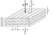
次に、本発明の液晶表示装置においては、前記下反射偏光層は、プリズム形状を成す誘電体干渉膜を積層した構造である構成とすることもできる。 Next, in the liquid crystal display device of the present invention, the lower reflective polarizing layer may have a structure in which a dielectric interference film having a prism shape is laminated.
本発明の液晶表示装置に係る下反射偏光層について、図6を参照して以下に説明する。図6は、プリズム形状を成す誘電体干渉膜を積層して構成された反射偏光層の一例を示す斜視図である。
図6に示す反射偏光層は、表面に周期的な溝を形成した基板60上に、Siからなる層61と、SiO2からなる層62もしくはSiO2等からなる層61と、TiO2、Ta2O5等からなる層62を交互に複数積層して形成された、いわゆる3次元フォトニック結晶層である。このように、プリズム形状を成す層が積層された構成のフォトニック結晶は、光の伝搬特性に異方性を有しており、図示上面側から光が入射された場合には、この入射光の基板60の溝に垂直な方向の成分はフォトニック結晶を透過され、前記溝に平行な成分は反射されるようになっている。すなわち、図6に示す反射偏光層を透過した光Etは、基板60の溝に垂直な偏光となり、反射された光Erは、前記溝に平行な偏光となる。尚、前記層61,62の積層ピッチDは、0.5μm程度とされ、基板60上に形成された溝のピッチPは、0.5μm程度とされる。上記構成の下反射偏光層は、図3に示す液晶表示装置においては、透過軸が図3の紙面に垂直となるよう配置されている。つまり、図6に示す基板60の溝が、図3の紙面に平行となるように配置されている。
The lower reflective polarizing layer according to the liquid crystal display device of the present invention will be described below with reference to FIG. FIG. 6 is a perspective view showing an example of a reflective polarization layer formed by laminating a dielectric interference film having a prism shape.
Reflective polarizing layer shown in FIG. 6, on the
また、図6に示す反射偏光層の光透過率は、前記誘電体干渉膜の積層数により制御することができる。すなわち、誘電体干渉膜の積層数の増加に伴い、反射偏光層の光透過率が減少し、反射率が上昇する。従って、この積層数を制御することで任意の光透過率を有する反射偏光層とすることができる。具体的な透過率と積層数の関係は、特に限定されるものではないが、積層数を8〜12層とした場合に、光透過率が30%(反射率70%)となる。
光 Further, the light transmittance of the reflective polarizing layer shown in FIG. 6 can be controlled by the number of stacked dielectric interference films. That is, as the number of stacked dielectric interference films increases, the light transmittance of the reflective polarizing layer decreases, and the reflectance increases. Therefore, by controlling the number of layers, a reflective polarizing layer having an arbitrary light transmittance can be obtained. Although the specific relationship between the transmittance and the number of layers is not particularly limited, when the number of layers is 8 to 12, the light transmittance is 30% (
次に、本発明の液晶表示装置では、前記下反射偏光層は、金属反射膜に複数の微細なスリット状の開口部を設けた構成としても良い。この構成を図7を参照して以下に詳細に説明する。図7は、金属反射膜に複数の微細なスリットを設けた反射偏光層の一例を示す斜視図である。
図7に示す反射偏光層は、基板70上に形成されたアルミニウムや銀などの高反射率の金属反射膜71に、複数のスリット72を所定のピッチで形成したものである。複数のスリット72は、互いに平行とされ、スリット幅Psは各スリット72でほぼ同一とされている。各部の寸法は、特に限定されるものではないが、この金属反射膜71の膜厚dは、2〜400nm程度とされ、スリット72の幅Psは、30nm〜300nmとされ、1本の金属反射膜71の幅Pmは、30nm〜300nmとされる。
このような構成の反射偏光層は、上面側から光が入射されると、スリット72の長さ方向に平行な成分は反射され、スリット72の長さ方向に垂直な成分は透過されるようになっている。つまり、図7に示す反射偏光層を透過した光Etは、スリット72に垂直な偏光となり、この反射偏光層により反射された光Erは、スリット72に平行な偏光となる。
Next, in the liquid crystal display device of the present invention, the lower reflective polarizing layer may have a configuration in which a plurality of fine slit-shaped openings are provided in the metal reflective film. This configuration will be described in detail below with reference to FIG. FIG. 7 is a perspective view illustrating an example of a reflective polarizing layer in which a plurality of fine slits are provided in a metal reflective film.
The reflective polarizing layer shown in FIG. 7 has a structure in which a plurality of
The reflective polarizing layer having such a configuration is configured such that when light is incident from the upper surface side, a component parallel to the length direction of the
上記構成の下反射偏光層は、図3に示す液晶表示装置においては、透過軸が図3の紙面に垂直となるよう配置されている。つまり、図7に示すスリット72の長さ方向が、図3の紙面に平行となるように配置されている。また、この反射偏光層の一部に照明装置の光を透過させるための開口部が設けられている。
(3) In the liquid crystal display device shown in FIG. 3, the lower reflective polarizing layer having the above configuration is arranged such that the transmission axis is perpendicular to the plane of FIG. That is, the
また、図7に示す反射偏光層の光透過率は、前記金属反射膜の膜厚により制御することができる。すなわち、金属反射膜の膜厚の増加に伴って反射偏光層の光透過率が減少し、反射率が上昇する。従って、この膜厚を制御することで任意の光透過率を有する反射偏光層とすることができる。具体的な透過率と膜厚の関係は、特に限定されるものではないが、膜厚を2〜4nmとした場合に、光透過率が30%(反射率70%)となる。
光 Further, the light transmittance of the reflective polarizing layer shown in FIG. 7 can be controlled by the thickness of the metal reflective film. That is, as the thickness of the metal reflection film increases, the light transmittance of the reflective polarizing layer decreases, and the reflectance increases. Therefore, by controlling this film thickness, a reflective polarizing layer having an arbitrary light transmittance can be obtained. The specific relationship between the transmittance and the film thickness is not particularly limited, but when the film thickness is 2 to 4 nm, the light transmittance is 30% (
次に、本発明の電子機器は、先に記載の本発明の液晶表示装置を備えたことを特徴とする。この構成によれば、透過モード時に格段に明るい表示が得られる優れた表示部を備えた電子機器を実現することができる。 Next, an electronic apparatus according to the present invention includes the above-described liquid crystal display device according to the present invention. According to this configuration, it is possible to realize an electronic device including an excellent display unit capable of obtaining a much brighter display in the transmission mode.
以上、詳細に説明したように、本発明の液晶表示装置は、透過モードと反射モードを切替ながら使用する半透過反射型の液晶表示装置において、下基板の内面側に下反射偏光層を設け、この下反射偏光層の下側に下偏光層を設けた構成としたので、透過モードにおいては、照明装置から出射される光の利用効率を向上させて明るい表示を実現することができ、反射モードにおいては、暗表示をより暗くしてコントラストの向上を実現することができる。 As described above in detail, the liquid crystal display device of the present invention is a transflective liquid crystal display device used while switching between the transmission mode and the reflection mode, in which a lower reflective polarizing layer is provided on the inner surface side of the lower substrate, Since the lower polarizing layer is provided below the lower reflective polarizing layer, in the transmission mode, the utilization efficiency of light emitted from the illumination device is improved, and a bright display can be realized. In, the contrast can be improved by making the dark display darker.
次に、本発明の電子機器は、先に記載の本発明の液晶表示装置を備えたことにより、透過モード時に格段に明るい表示が得られ、コントラストに優れた表示部を備えた電子機器を実現することができる。 Next, the electronic device of the present invention includes the above-described liquid crystal display device of the present invention, so that an extremely bright display can be obtained in the transmission mode, and an electronic device having a display unit with excellent contrast is realized. can do.
以下、本発明の第1の実施形態を図面を参照して説明する。
図1は本実施形態の液晶表示装置の部分断面構造を示す図である。本実施形態は、パッシブマトリクス方式の半透過反射型カラー液晶表示装置の例である。尚、以下の図面においては、図面を見やすくするため、各構成要素の膜厚や寸法の比率などは適宜異ならせてある。
Hereinafter, a first embodiment of the present invention will be described with reference to the drawings.
FIG. 1 is a diagram showing a partial cross-sectional structure of the liquid crystal display device of the present embodiment. The present embodiment is an example of a passive matrix type transflective color liquid crystal display device. Note that, in the following drawings, the film thickness, the ratio of dimensions, and the like of each component are appropriately changed in order to make the drawings easy to see.
本実施形態の液晶表示装置1は、図1に示すように、下基板2と上基板3とが対向配置されてこの上下基板2,3に挟まれた空間にSTN(Super Twisted Nematic)液晶からなる液晶4が挟持されて概略構成された液晶パネル1と、この液晶パネル1の後面側(下基板2の外面側)に配設されたバックライト(照明装置)5とを備えて概略構成されている。
As shown in FIG. 1, a liquid
ガラスや樹脂などからなる下基板2の内面側には、図6に示すものと同様の構成の下反射偏光層6が形成され、この下反射偏光層6上にITO等の透明導電膜からなるストライプ状の電極8が図示横方向に延在し、この電極8を覆うようにポリイミド等からなる配向膜9が積層されている。また、前記下基板2の外面側には、下偏光板(下偏光層)20と、反射偏光板21がこの順に設けられている。尚、この下偏光板20の透過軸と反射偏光板21の透過軸は、ほぼ平行となるように配置されている。
A lower reflective
一方、ガラスや樹脂などからなる上基板3の内面側には、前記下基板2の電極8と直交するように赤、緑および青のカラーフィルタ11が紙面垂直方向に延在してこの順番に繰り返し配列しており、その上にはこのカラーフィルタ11によって形成された凹凸を平坦化するための平坦化膜12が積層されている。そして平坦化膜12上に、ITO等の透明導電膜からなるストライプ状の電極14が紙面垂直方向に延在しており、この電極14上にポリイミド等からなる配向膜15が積層形成されている。また、上基板3の外面側には、前方散乱板16と、位相差板17と、上偏光板13がこの順に上基板3上に積層されて設けられている。
バックライト5の下面側(液晶パネル1と反対側)には、反射板18が設けられている。
On the other hand, on the inner surface side of the
On the lower surface side of the backlight 5 (the side opposite to the liquid crystal panel 1), a
前記下反射偏光層6は、図6に示すように、プリズム形状を成す誘電体干渉膜を積層形成した構成であり、図6に示す溝60の方向は、下偏光板20の透過軸と、ほぼ平行とされている。すなわち、この下反射偏光層6の透過軸と、下偏光板20の透過軸とがほぼ直交するように配置されている。これにより、反射モード時に下反射偏光層6を透過した光を、効率よく下偏光板20に吸収させることができるので、反射モードの暗表示をより暗くして、液晶表示装置のコントラストを向上させることができる。
As shown in FIG. 6, the lower reflective
また、透過モードと反射モードの明るさのバランスも、前記下反射偏光層6の積層数を調節することで任意に設定することができる。例えば、透過モード時の明るさを重視するならば、下反射偏光層6の積層数を減らして形成し、下反射偏光層6の透過率を高くすればよい。
The balance between the brightness in the transmission mode and the brightness in the reflection mode can be arbitrarily set by adjusting the number of layers of the lower reflective
上記基本構成を有する本実施形態の液晶表示装置は、下基板2の内側に、下反射偏光層6を形成して構成されており、従来下基板の外面側に設けることが必須であった1/4波長板が省略されている。このような構成としたことにより本実施形態の液晶表示装置は、反射モード、透過モードいずれにおいても視認性に優れる表示が可能である。特に、透過モードにおいては、下基板2の外面側に1/4波長板が設けられていないので、バックライト5から出射された光のうち下反射偏光層6の裏面側で反射され、バックライト5側へ戻った光を反射板18で反射させて再び液晶パネル1側に戻すことができる。この構造によりバックライト5の光を有効に表示に利用することができるので、その表示の明るさを従来よりも格段に向上させることができる。
The liquid crystal display device of the present embodiment having the above-described basic configuration is configured such that the lower reflective
また、本実施形態の液晶表示装置の構成によれば、下偏光板20の外面側に、反射偏光板21が設けられているので、バックライト5から出射された光のうち、反射偏光板21の透過軸に平行でない成分は、反射偏光板21に反射されてバックライト5側へ戻され、反射板18との間で反射を繰り返すうちに、その偏光状態が変化して反射偏光板21を透過できるようになり、表示に利用できる光となる。従って、本実施形態の液晶表示装置においては、下偏光板20による光の吸収がほとんど生じないので、バックライト5の光をより効率よく表示に利用することができ、透過モード時の表示の明るさに優れた液晶表示とされている。
Further, according to the configuration of the liquid crystal display device of the present embodiment, since the reflective
(第2の実施形態)
本実施の形態において、液晶表示装置の全体構成は図1に示した第1の実施の形態と同様であるため、詳細な説明は省略する。本実施形態の液晶表示装置が、第1の実施形態の液晶表示装置と異なる点は、下反射偏光層6の直上に、カラーフィルタ11が積層されて形成されており、このカラーフィルタ11上にカラーフィルタ11の凹凸を平坦化するための平坦化膜12が設けられている点であり、この部分のみについて図2を用いて説明する。図2は本実施形態の液晶表示装置の部分断面構造を示す図である。なお、図2において図1と共通の構成要素には同一の符号を付している。
(Second embodiment)
In the present embodiment, the overall configuration of the liquid crystal display device is the same as that of the first embodiment shown in FIG. The difference between the liquid crystal display device of the present embodiment and the liquid crystal display device of the first embodiment is that a
図2に示す本実施形態の液晶表示装置においては、下反射偏光層6上にカラーフィルタ11が設けられていることにより、反射モード時の色ずれや視差を低減することができる。これは、カラーフィルタ11が下反射偏光層6の直上に設けられていることにより、1つの色素層(例えばR画素)を透過した後、下反射偏光層6により反射され、再び同じ色素層を透過するためである。
In the liquid crystal display device of the present embodiment shown in FIG. 2, since the
(電子機器)
上記各実施の形態の液晶表示装置を備えた電子機器の例について説明する。
(Electronics)
An example of an electronic device including the liquid crystal display device of each of the above embodiments will be described.
図8(a)は、携帯電話の一例を示した斜視図である。この図において、符号1000は携帯電話本体を示し、符号1001は上記の液晶表示装置を用いた液晶表示部を示している。
FIG. 8A is a perspective view illustrating an example of a mobile phone. In this figure,
図8(b)は、腕時計型電子機器の一例を示した斜視図である。この図において、符号1100は時計本体を示し、符号1101は上記の液晶表示装置を用いた液晶表示部を示している。
FIG. 8B is a perspective view showing an example of a wristwatch-type electronic device. In this figure,
図8(c)は、ワープロ、パソコンなどの携帯型情報処理装置の一例を示した斜視図である。図8(c)において、符号1200は情報処理装置、符号1202はキーボードなどの入力部、符号1204は情報処理装置本体、符号1206は上記の液晶表示装置を用いた液晶表示部を示している。
FIG. 8C is a perspective view showing an example of a portable information processing device such as a word processor or a personal computer. 8C,
以上の図8(a)〜(c)に示す電子機器は、上記実施の形態の液晶表示装置を用いた液晶表示部を備えているので、透過モードで明るい表示が得られる表示部を有する電子機器を実現することができる。 Since the electronic devices shown in FIGS. 8A to 8C include the liquid crystal display portion using the liquid crystal display device of the above embodiment, the electronic device having the display portion capable of obtaining a bright display in the transmission mode is provided. Equipment can be realized.
以下、実施例により本発明の効果を明らかにするが、本発明は以下の実施例に限定されるものではない。
(実施例1)
実施例1として、図2に示す構成の液晶表示装置を作製した。いずれの液晶表示装置もドット数160ドット×120ドット、ドットピッチ0.24mmのパッシブマトリクス方式の半透過反射型カラー液晶表示装置とした。
実施例1の液晶表示装置において、下反射偏光層6は、図6に示す構成の誘電体干渉膜を積層形成したものとした。この下反射偏光層6の誘電体干渉膜の積層数は12層(膜厚約6μm)とし、プリズム形状の溝のピッチを3μmとした。この下反射偏光層の反射軸に平行な偏光に対する透過率は24%であった。
Hereinafter, the effects of the present invention will be clarified by examples, but the present invention is not limited to the following examples.
(Example 1)
As Example 1, a liquid crystal display device having a configuration shown in FIG. 2 was manufactured. Each of the liquid crystal display devices was a passive matrix transflective color liquid crystal display device having a dot count of 160 dots × 120 dots and a dot pitch of 0.24 mm.
In the liquid crystal display device of Example 1, the lower reflective
(実施例2)
次に、実施例2として、下反射偏光層6の誘電体干渉膜の積層数を5層とした以外は、上記実施例1と同様にして、半透過反射型カラー液晶表示装置を作製した。この下反射偏光層の反射軸に平行な偏光に対する透過率は65%であった。
(Example 2)
Next, as Example 2, a transflective color liquid crystal display device was manufactured in the same manner as in Example 1 except that the number of stacked dielectric interference films of the lower reflective
(比較例1)
次に、比較例1として、図9に示す従来の構成の液晶表示装置を作製した。この液晶表示装置も、上記実施例1の液晶表示装置と同様にドット数160ドット×120ドット、ドットピッチ0.24mmのパッシブマトリクス方式の半透過反射型カラー液晶表示装置とした。
(Comparative Example 1)
Next, as Comparative Example 1, a liquid crystal display device having a conventional configuration shown in FIG. 9 was manufactured. This liquid crystal display was a passive matrix type transflective color liquid crystal display having a dot count of 160 dots × 120 dots and a dot pitch of 0.24 mm similarly to the liquid crystal display of Example 1 described above.
(評価)
上記実施例1,2および比較例1の液晶表示装置について、透過モード、反射モードそれぞれの表示の明るさに対応する透過率および反射率を測定した。また、透過モード、反射モードそれぞれのコントラストも測定した。これらの測定結果を表1に示す。
表1に示すように、比較例1の液晶表示装置に比して、本発明の構成である実施例1の液晶表示装置は、透過率が3倍程度に向上していることが確認された。また、透過時のコントラストも1.6倍となり、大幅に向上していることが確認された。これは、実施例1の液晶表示装置がバックライト5の光を効率的に表示に利用することができるためである。また、下反射偏光層6の積層数を減らして作製した実施例2の液晶表示装置では、透過率が15%と実施例1の液晶表示装置と比較しても2倍以上の顕著な向上が確認された。
(Evaluation)
With respect to the liquid crystal display devices of Examples 1 and 2 and Comparative Example 1, the transmittance and the reflectance corresponding to the display brightness in the transmission mode and the reflection mode were measured. Further, the contrast in each of the transmission mode and the reflection mode was also measured. Table 1 shows the measurement results.
As shown in Table 1, it was confirmed that the transmittance of the liquid crystal display device of Example 1, which is the configuration of the present invention, was improved about three times as compared with the liquid crystal display device of Comparative Example 1. . Also, the contrast at the time of transmission was 1.6 times, and it was confirmed that the contrast was greatly improved. This is because the liquid crystal display device of the first embodiment can efficiently use the light of the
一方、反射モードにおいては、実施例1の液晶表示装置の反射率は30%であり、比較例1の液晶表示装置と同等であったが、反射モードのコントラストは向上していることが確認された。このコントラストの向上は、明表示の明るさは同等であるが、暗表示はより暗くなったためである。また、実施例2の液晶表示装置では、透過モードの明るさを重視して設計したため、実施例1の液晶表示装置に比して、反射率は低下し、反射モードのコントラストもやや低下した。 On the other hand, in the reflection mode, the reflectance of the liquid crystal display device of Example 1 was 30%, which was equivalent to that of the liquid crystal display device of Comparative Example 1, but it was confirmed that the contrast of the reflection mode was improved. Was. This improvement in contrast is due to the fact that the brightness of the bright display is the same, but the dark display is darker. Further, in the liquid crystal display device of Example 2, since the design was made with emphasis on the brightness in the transmission mode, the reflectance and the contrast in the reflection mode were slightly lower than those of the liquid crystal display device of Example 1.

1 液晶表示装置
2 下基板
3 上基板
4 液晶
5 バックライト(照明装置)
6 下反射偏光層
11 カラーフィルタ
13 上偏光板(上偏光層)
20 下偏光板(下偏光層)
21 反射偏光板
6 Lower reflective
20 Lower polarizing plate (Lower polarizing layer)
21 Reflective polarizing plate
Claims (10)
前記下反射偏光層が、透過軸と該透過軸に直交する反射軸を有し、入射する光の前記反射軸に平行な成分の一部を反射し、一部を透過する半透過反射型の反射偏光層とされ、
前記下反射偏光層の下側に、下偏光層が設けられたことを特徴とする液晶表示装置。 A liquid crystal is sandwiched between an upper substrate and a lower substrate facing each other, a liquid crystal panel including an upper polarizing layer and a lower reflective polarizing layer above and below the liquid crystal, and an illumination provided on an outer surface side of the liquid crystal panel. A transflective liquid crystal display device comprising a device and performing display by switching between a transmission mode and a reflection mode,
The lower reflective polarizing layer has a transmission axis and a reflection axis orthogonal to the transmission axis, reflects a part of a component parallel to the reflection axis of incident light, and is a transflective type that transmits part. A reflective polarizing layer,
A liquid crystal display device, wherein a lower polarizing layer is provided below the lower reflective polarizing layer.
An electronic apparatus comprising the liquid crystal display device according to claim 1.
Priority Applications (1)
| Application Number | Priority Date | Filing Date | Title |
|---|---|---|---|
| JP2003345845A JP2004038204A (en) | 2003-10-03 | 2003-10-03 | Liquid crystal display and electronic equipment |
Applications Claiming Priority (1)
| Application Number | Priority Date | Filing Date | Title |
|---|---|---|---|
| JP2003345845A JP2004038204A (en) | 2003-10-03 | 2003-10-03 | Liquid crystal display and electronic equipment |
Related Parent Applications (1)
| Application Number | Title | Priority Date | Filing Date |
|---|---|---|---|
| JP2001230172A Division JP3778025B2 (en) | 2001-06-06 | 2001-07-30 | Liquid crystal display device and electronic device |
Publications (2)
| Publication Number | Publication Date |
|---|---|
| JP2004038204A true JP2004038204A (en) | 2004-02-05 |
| JP2004038204A5 JP2004038204A5 (en) | 2008-08-28 |
Family
ID=31712811
Family Applications (1)
| Application Number | Title | Priority Date | Filing Date |
|---|---|---|---|
| JP2003345845A Withdrawn JP2004038204A (en) | 2003-10-03 | 2003-10-03 | Liquid crystal display and electronic equipment |
Country Status (1)
| Country | Link |
|---|---|
| JP (1) | JP2004038204A (en) |
Cited By (3)
| Publication number | Priority date | Publication date | Assignee | Title |
|---|---|---|---|---|
| WO2006092878A1 (en) * | 2005-03-02 | 2006-09-08 | Nitto Denko Corporation | Liquid crystal display panel with improved image contrast |
| WO2010001618A1 (en) * | 2008-07-04 | 2010-01-07 | 三井化学株式会社 | Polarizing diffusion film, method for producing polarizing diffusion film, and liquid crystal display device comprising polarizing diffusion film |
| JP2011007998A (en) * | 2009-06-25 | 2011-01-13 | Ricoh Co Ltd | Optical writing device and image forming apparatus |
Citations (3)
| Publication number | Priority date | Publication date | Assignee | Title |
|---|---|---|---|---|
| JPH11242214A (en) * | 1998-02-26 | 1999-09-07 | Seiko Epson Corp | Liquid crystal device and electronic equipment |
| JP2000227590A (en) * | 1999-02-08 | 2000-08-15 | Toshiba Corp | Display device |
| JP2001083509A (en) * | 1999-09-14 | 2001-03-30 | Seiko Epson Corp | Liquid crystal display device and electronic instrument using the same |
-
2003
- 2003-10-03 JP JP2003345845A patent/JP2004038204A/en not_active Withdrawn
Patent Citations (3)
| Publication number | Priority date | Publication date | Assignee | Title |
|---|---|---|---|---|
| JPH11242214A (en) * | 1998-02-26 | 1999-09-07 | Seiko Epson Corp | Liquid crystal device and electronic equipment |
| JP2000227590A (en) * | 1999-02-08 | 2000-08-15 | Toshiba Corp | Display device |
| JP2001083509A (en) * | 1999-09-14 | 2001-03-30 | Seiko Epson Corp | Liquid crystal display device and electronic instrument using the same |
Cited By (13)
| Publication number | Priority date | Publication date | Assignee | Title |
|---|---|---|---|---|
| US7456915B2 (en) | 2004-03-26 | 2008-11-25 | Nitto Denko Corporation | Liquid crystal display panel with broadband interference polarizers |
| US7911557B2 (en) | 2004-03-26 | 2011-03-22 | Nitto Denko Corporation | Liquid crystal display panel |
| WO2006092878A1 (en) * | 2005-03-02 | 2006-09-08 | Nitto Denko Corporation | Liquid crystal display panel with improved image contrast |
| JP2010286843A (en) * | 2008-07-04 | 2010-12-24 | Mitsui Chemicals Inc | Polarizing diffusion film, and liquid crystal display device comprising polarizing diffusion film |
| JP4560584B1 (en) * | 2008-07-04 | 2010-10-13 | 三井化学株式会社 | Polarizing diffusion film and liquid crystal display device including polarizing diffusion film |
| JP2010286818A (en) * | 2008-07-04 | 2010-12-24 | Mitsui Chemicals Inc | Polarizing diffusion film, liquid crystal display device comprising polarizing diffusion film |
| JP4531117B2 (en) * | 2008-07-04 | 2010-08-25 | 三井化学株式会社 | Method for producing polarizing diffusion film and method for producing liquid crystal display device including polarizing diffusion film |
| WO2010001618A1 (en) * | 2008-07-04 | 2010-01-07 | 三井化学株式会社 | Polarizing diffusion film, method for producing polarizing diffusion film, and liquid crystal display device comprising polarizing diffusion film |
| JPWO2010001618A1 (en) * | 2008-07-04 | 2011-12-15 | 三井化学株式会社 | Method for producing polarizing diffusion film and method for producing liquid crystal display device including polarizing diffusion film |
| EP2466368A1 (en) * | 2008-07-04 | 2012-06-20 | Mitsui Chemicals, Inc. | Polarizing diffuser film, method for producing polarizing diffuser film, and liquid crystal display device comprising polarizing diffuser film |
| CN101990649B (en) * | 2008-07-04 | 2013-03-20 | 三井化学株式会社 | Polarizing diffusion film, method for producing polarizing diffusion film, and liquid crystal display device comprising polarizing diffusion film |
| US8462297B2 (en) | 2008-07-04 | 2013-06-11 | Mitsui Chemicals, Inc. | Polarizing diffuser film, method for producing polarizing diffuser film, and liquid crystal display device comprising polarizing diffuser film |
| JP2011007998A (en) * | 2009-06-25 | 2011-01-13 | Ricoh Co Ltd | Optical writing device and image forming apparatus |
Similar Documents
| Publication | Publication Date | Title |
|---|---|---|
| JP3598987B2 (en) | Liquid crystal display and electronic equipment | |
| JP2003202560A (en) | Liquid crystal display device and electronic apparatus | |
| KR100485561B1 (en) | Liquid crystal device and electronic apparatus | |
| JP2008107687A (en) | Liquid crystal display, optical film and terminal device | |
| KR100483781B1 (en) | Liquid crystal display device and electronic apparatus | |
| JP3879661B2 (en) | Liquid crystal display device and electronic device | |
| JP2006501516A (en) | Liquid crystal display | |
| JP2006139239A (en) | Display panel and display device having the same | |
| JP3873667B2 (en) | Liquid crystal display device and electronic device | |
| JP3705184B2 (en) | Liquid crystal device and electronic device | |
| JP2000147502A (en) | Liquid crystal device and electronic equipment | |
| JP3843907B2 (en) | Liquid crystal display device and electronic device | |
| JP3778025B2 (en) | Liquid crystal display device and electronic device | |
| JPH08184844A (en) | Reflection type liquid crystal display device | |
| JP2004038204A (en) | Liquid crystal display and electronic equipment | |
| JP2003228067A (en) | Liquid crystal display device and electronic apparatus | |
| JP2004109986A (en) | Liquid crystal display and electronic appliance | |
| JP3899711B2 (en) | Liquid crystal device and electronic device | |
| JP2003043473A (en) | Liquid crystal display device and electronic instrument | |
| KR100907478B1 (en) | Liquid crystal display device | |
| JP2004029202A (en) | Liquid crystal display and electronic equipment | |
| JP2004219553A (en) | Liquid crystal display device and electronic appliance | |
| JP4356725B2 (en) | Liquid crystal device and electronic device | |
| JP2004145097A (en) | Liquid crystal display device, and electronic apparatus equipped with same | |
| JP4122926B2 (en) | Liquid crystal display device and electronic device |
Legal Events
| Date | Code | Title | Description |
|---|---|---|---|
| A521 | Written amendment |
Free format text: JAPANESE INTERMEDIATE CODE: A523 Effective date: 20080708 |
|
| A621 | Written request for application examination |
Free format text: JAPANESE INTERMEDIATE CODE: A621 Effective date: 20080708 |
|
| A521 | Written amendment |
Free format text: JAPANESE INTERMEDIATE CODE: A821 Effective date: 20080710 |
|
| A977 | Report on retrieval |
Free format text: JAPANESE INTERMEDIATE CODE: A971007 Effective date: 20101019 |
|
| A131 | Notification of reasons for refusal |
Free format text: JAPANESE INTERMEDIATE CODE: A131 Effective date: 20101026 |
|
| A761 | Written withdrawal of application |
Free format text: JAPANESE INTERMEDIATE CODE: A761 Effective date: 20101108 |
|
| A521 | Written amendment |
Free format text: JAPANESE INTERMEDIATE CODE: A821 Effective date: 20101109 |