JP2004037925A - Imaging apparatus - Google Patents
Imaging apparatus Download PDFInfo
- Publication number
- JP2004037925A JP2004037925A JP2002196169A JP2002196169A JP2004037925A JP 2004037925 A JP2004037925 A JP 2004037925A JP 2002196169 A JP2002196169 A JP 2002196169A JP 2002196169 A JP2002196169 A JP 2002196169A JP 2004037925 A JP2004037925 A JP 2004037925A
- Authority
- JP
- Japan
- Prior art keywords
- lens
- lens group
- object side
- image
- zoom lens
- Prior art date
- Legal status (The legal status is an assumption and is not a legal conclusion. Google has not performed a legal analysis and makes no representation as to the accuracy of the status listed.)
- Pending
Links
Images


Abstract
Description
【0001】
【発明が属する技術分野】
本発明は、CCD(Charge Coupled Device 電荷結合素子)やCMOSセンサ(Complementary Metal−oxide Semiconductor 相補性金属酸化膜半導体センサ)等の受光面上に形成された光学像を電気信号に変換する撮像素子を備えた撮像装置に関し、特にデジタルカメラ;パーソナルコンピュータ,モバイルコンピュータ,携帯電話,情報携帯端末(PDA:Personal Digital Assistance)等に内蔵又は外付けされるカメラの主たる構成要素である撮像装置に関するものである。詳しくは、特にズームレンズ系を備えた小型の撮像装置に関する。
【0002】
【従来の技術】
近年、銀塩フィルムの代わりにCCDやCMOSセンサなどの撮像素子を用いて、光学像を電気信号に変換し、そのデータをデジタル化して記録したり転送したりするデジタルカメラが急速に普及してきている。このようなデジタルカメラにおいては、最近、200万画素や300万画素といった高画素を有するCCDやCMOSセンサが比較的安価に提供されるようになったため、撮像素子を装着した高性能な撮像装置に対する需要が非常に増大しているおり、特に、画質を劣化させずに変倍が可能なズームレンズ系を搭載したコンパクトな撮像装置が切望されている。
【0003】
さらに、近年では、半導体素子等の画像処理能力の向上により、パーソナルコンピュータ,モバイルコンピュータ,携帯電話,情報携帯端末(PDA:Personal Digital Assistance)等に撮像装置が内蔵又は外付けされるようになっており、高性能な撮像装置に対する需要に拍車をかけている。
【0004】
このような撮像装置に用いられるズームレンズ系としては、最も物体側に配置されたレンズ群が負のパワーを有する、いわゆるマイナスリードのズームレンズ系が数多く提案されている。マイナスリードのズームレンズ系は、広角化が容易であり、光学的ローパスフィルタの挿入に必要なレンズバックを確保しやすい等の特徴を有している。
【0005】
マイナスリードのズームレンズ系としては、従来から銀塩フィルム用カメラの撮影レンズ系として提案されたズームレンズ系がある。しかしながら、これらのズームレンズ系は、特に最短焦点距離状態でのレンズ系の射出瞳位置が比較的像面の近くに位置するため、特に高画素を有する撮像素子の各画素に対応して設けられたマイクロレンズの瞳と整合せず、周辺光量が十分に確保できないという問題があった。また、変倍時に射出瞳位置が大きく変動するため、マイクロレンズの瞳の設定が困難であるという問題もあった。また、そもそも銀塩フィルムと撮像素子では、求められる空間周波数特性等の光学性能が全く異なるため、撮像素子に要求される十分な光学性能を確保できなかった。このため、撮像素子を備えた撮像装置に最適化された専用のズームレンズ系を開発する必要が生じている。
【0006】
一方、撮像装置を小型化するために、ズームレンズ系を光路の途中で折り曲げ、光路長を変化させずにコンパクト化を図かる提案が成されている。例えば、特開平11−196303号公報には、マイナスリードのズームレンズ系において、光路上に反射面を設けて略90°折り曲げた後、移動レンズ群を経て撮像素子上に光学像を形成する撮像装置が提案されている。同公報開示の撮像装置は、負メニスカス形状の固定レンズ素子の像側に反射面を設け、この反射面で光路を略90°折り曲げた後、可動の2つの正レンズ群、固定の正レンズ群を経て撮像素子に至る構成を有している。
【0007】
また別の例として、特開平11−258678号公報には、負メニスカス形状の固定レンズ素子、可動の正レンズ群の像側に反射面を設け、この反射面で光路を略90°折り曲げた後、正レンズ群を経て撮像素子に至る構成が開示されている。
【0008】
【発明が解決しようとする課題】
しかしながら、上記2つの公報においては、鏡胴の構成のみしか開示されておらず、具体的なズームレンズ系の構成が不明であるという問題があった。ズームレンズ系を備えた撮像装置では、体積的に最も大きな空間を占めるズームレンズ系を最適化しない限り、全体の小型化を達成することは困難である。
【0009】
本発明は、以上の課題に鑑み、高性能で高倍率ズームレンズ系を備えながら、コンパクトな、撮像装置を提供することを目的とする。
【0010】
【課題を解決するための手段】
上記課題を解決するために、本発明に係る撮像装置は、複数のレンズ群を有し、該複数のレンズ群間の間隔を変化させることによって物体の光学像を連続的に光学的に変倍可能に形成するズームレンズ系と、ズームレンズ系が形成した光学像を電気信号に変換する撮像素子を備えた撮像装置であって、前記ズームレンズ系は、物体側から順に、全体として負のパワーを有し、光束を略90°折り曲げる反射面を含む第1レンズ群と、前記第1レンズ群との間に変化可能な空気間隔を隔てて配置され、パワーを有する第2レンズ群と、を含み、前記第1レンズ群は、物体側から順に、負のパワーを有する負レンズ素子と、反射面と、からなることを特徴とする。
【0011】
また、本発明の別の側面は、上記撮像装置を含むデジタルカメラであることを特徴とする。なお、デジタルカメラの語は、従来は専ら光学的な静止画を記録するものを指していたが、動画を同時に扱えるものや家庭用のデジタルビデオカメラも提案されており、現在では特に区別されなくてなってきている。したがって、以下、デジタルカメラの語は、デジタルスチルカメラやデジタルムービー等の撮像素子の受光面上に形成された光学像を電気信号に変換する撮像素子を備えた撮像装置を主たる構成要素とするカメラをすべて含むものとする。
【0012】
【発明の実施の形態】
以下、図面を参照して、本発明の一実施形態について説明する。
【0013】
本発明の一実施形態である撮像装置は、例えば図19に示すように、物体側(被写体側)から順に、物体の光学像を変倍可能に形成するズームレンズ系とTL、光学的ローパスフィルタLPFと、ズームレンズ系TLにより形成された光学像を電気的な信号に変換する撮像素子SRと、で構成されている。また、ズームレンズ系は、内部に反射面を有するプリズムPRを有する第1レンズ群Gr1と、後続するレンズ群を含んでいる。撮像装置は、デジタルカメラ;ビデオカメラ;パーソナルコンピュータ,モバイルコンピュータ,携帯電話,情報携帯端末(PDA:Personal Digital Assistance)等に内蔵又は外付けされるカメラの主たる構成要素である。
【0014】
ズームレンズ系TLは、第1レンズ群Gr1を含む複数のレンズ群から構成されており、各レンズ群の間の間隔を変化させることによって光学像の大きさを変化させることが可能である。第1レンズ群Gr1は負のパワーを有しており、内部に物体光の光軸を略90°折り曲げるプリズムPRを有する。
【0015】
光学ローパスフィルタLPFは、撮影レンズ系の空間周波数特性を調整し撮像素子で発生する色モアレを解消するための特定の遮断周波数を有している。実施形態の光学ローパスフィルタは、結晶軸を所定方向に調整された水晶等の複屈折材料や偏光面を変化させる波長板等を積層して作成された複屈折型ローパスフィルタである。なお、光学ローパスフィルタとしては、必要な光学的な遮断周波数の特性を回折効果により達成する位相型ローパスフィルタ等を採用してもよい。
【0016】
撮像素子SRは、複数の画素を有するCCDからなり、ズームレンズ系が形成した光学像をCCDで電気信号に変換する。撮像素子SRで生成された信号は、必要に応じて所定のデジタル画像処理や画像圧縮処理等を施されてデジタル映像信号としてメモリー(半導体メモリー,光ディスク等)に記録されたり、場合によってはケーブルを介したり赤外線信号に変換されたりして他の機器に伝送される。なお、CCDの代わりにCMOSセンサ(Complementary Metal−oxide Semiconductor)を用いてもよい。
【0017】
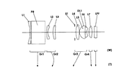
図1乃至図9は、本発明の第1乃至第9実施形態の撮像装置に含まれるズームレンズ系の最短焦点距離状態でのレンズ配置を示す構成図である。なお、各図においては、内部反射面を有するプリズムPRを平行平板で表し光路を直線的に表している。
【0018】
第1の実施形態のズームレンズ系は、物体側から像側へ順に、物体側に凸面を向けた負メニスカスレンズからなる第1レンズ素子L1とプリズムに相当する平板PRと、から構成される第1レンズ群Gr1と、両凹形状の第2レンズ素子L2と物体側に凸面を向けた正メニスカス形状の第3レンズ素子L3と、から構成される第2レンズ群Gr2と、絞りSTと、両凸形状の第4レンズ素子L4と両凹形状の第5レンズ素子L5とを接合してなる第1接合レンズ素子DL1から構成される第3レンズ群Gr3と、物体側に凹面を向けた正メニスカス形状の第6レンズ素子L6から構成される第4レンズ群Gr4と、物体側に凹面を向けた負メニスカス形状の第7レンズ素子L7とから構成される第5レンズ群Gr5と、から構成されている。さらに、このズームレンズ系の第5レンズ群Gr5の像側には、光学的ローパスフィルタに相当する平行平板LPFが配置されている。
【0019】
このズームレンズ系は、最短焦点距離状態から最長焦点距離状態へのズーミングに際して、第1レンズ群Gr1は像面に対して固定され、第2レンズ群Gr2は一旦像側へ移動した後で物体側へ移動するよう像側に凸のUターン状の軌跡を描いて移動し、第3レンズ群Gr3は、第3レンズ群Gr3の物体側に配置された絞りSTと一体となりほぼ単調に物体側へ移動し、第4レンズ群Gr4はほぼ単調に像側へ移動し、第5レンズ群Gr5は、第5レンズ群Gr5の像側に配置された平行平板LPFとともに、像面に対して固定されている。
【0020】
レンズ素子の面のうち、第2レンズ素子L2の両面と、第6レンズ素子L6の像側面と、第7レンズ素子L7の物体側面は、それぞれ非球面形状を有している。
【0021】
第2の実施形態のズームレンズ系は、物体側から像側へ順に、物体側に凸面を向けた負メニスカスレンズからなる第1レンズ素子L1、プリズムに相当する平板PR、物体側に凸面を向けた正メニスカス形状の第2レンズ素子L2とから構成される第1レンズ群Gr1と、物体側に凸面を向けた負メニスカス形状の第3レンズ素子L3と物体側に凸面を向けた正メニスカス形状の第4レンズ素子L4と、から構成される第2レンズ群Gr2と、絞りSTと、両凸形状の第5レンズ素子L5と両凹形状の第6レンズ素子L6とを接合してなる第1接合レンズ素子DL1から構成される第3レンズ群Gr3と、物体側に凹面を向けた正メニスカス形状の第7レンズ素子L7から構成される第4レンズ群Gr4と、物体側に凸面を向けた負メニスカス形状の第8レンズ素子L8とから構成される第5レンズ群Gr5と、から構成されている。さらに、このズームレンズ系の第5レンズ群Gr5の像側には、光学的ローパスフィルタに相当する平行平板LPFが配置されている。
【0022】
このズームレンズ系は、最短焦点距離状態から最長焦点距離状態へのズーミングに際して、第1レンズ群Gr1は像面に対して固定され、第2レンズ群Gr2は一旦像側へ移動した後で物体側へ移動するよう像側に凸のUターン状の軌跡を描いて移動し、第3レンズ群Gr3は、第3レンズ群Gr3の物体側に配置された絞りSTと一体となりほぼ単調に物体側へ移動し、第4レンズ群Gr4はほぼ単調に像側へ移動し、第5レンズ群Gr5は、第5レンズ群Gr5の像側に配置された平行平板LPFとともに、像面に対して固定されている。
【0023】
レンズ素子の面のうち、第1レンズ素子L1の物体側面、第3レンズ素子L3の両面、第7レンズ素子L7の像側面、第8レンズ素子L8の物体側面は、それぞれ非球面形状を有している。
【0024】
第3の実施形態のズームレンズ系は、物体側から像側へ順に、物体側に凸面を向けた負メニスカスレンズからなる第1レンズ素子L1とプリズムに相当する平板PRと、から構成される第1レンズ群Gr1と、物体側に凸面を向けた負メニスカス形状の第2レンズ素子L2と物体側に凸面を向けた正メニスカス形状の第3レンズ素子L3と、から構成される第2レンズ群Gr2と、絞りSTと、両凸形状の第4レンズ素子L4と両凹形状の第5レンズ素子L5とを接合してなる第1接合レンズ素子DL1から構成される第3レンズ群Gr3と、物体側に凹面を向けた正メニスカス形状の第6レンズ素子L6から構成される第4レンズ群Gr4と、物体側に凸面を向けた負メニスカス形状の第7レンズ素子L7とから構成される第5レンズ群Gr5と、から構成されている。さらに、このズームレンズ系の第5レンズ群Gr5の像側には、光学的ローパスフィルタに相当する平行平板LPFが配置されている。
【0025】
このズームレンズ系は、最短焦点距離状態から最長焦点距離状態へのズーミングに際して、第1レンズ群Gr1は像面に対して固定され、第2レンズ群Gr2は一旦像側へ移動した後で物体側へ移動するよう像側に凸のUターン状の軌跡を描いて移動し、第3レンズ群Gr3は、第3レンズ群Gr3の物体側に配置された絞りSTと一体となりほぼ単調に物体側へ移動し、第4レンズ群Gr4はほぼ単調に像側へ移動し、第5レンズ群Gr5は、第5レンズ群Gr5の像側に配置された平行平板LPFとともに、像面に対して固定されている。
【0026】
レンズ素子の面のうち、第2レンズ素子L2の両面と、第5レンズ素子L5の像側面と、第6レンズ素子L6の両面は、それぞれ非球面形状を有している。
【0027】
第4の実施形態のズームレンズ系は、物体側から像側へ順に、物体側に凸面を向けた負メニスカスレンズからなる第1レンズ素子L1とプリズムに相当する平板PRと、から構成される第1レンズ群Gr1と、物体側に凸面を向けた負メニスカス形状の第2レンズ素子L2と物体側に凸面を向けた正メニスカス形状の第3レンズ素子L3と、から構成される第2レンズ群Gr2と、絞りSTと、両凸形状の第4レンズ素子L4と、物体側に凹面を向けた正メニスカス形状の第5レンズ素子L5と物体側に凹面を向けた負メニスカス形状の第6レンズ素子L6を接合してなる第1接合レンズ素子DL1から構成される第3レンズ群Gr3と、両凸形状の第7レンズ素子L7から構成される第4レンズ群Gr4と、から構成されている。さらに、このズームレンズ系の第4レンズ群Gr4の像側には、光学的ローパスフィルタに相当する平行平板LPFが配置されている。
【0028】
このズームレンズ系は、最短焦点距離状態から最長焦点距離状態へのズーミングに際して、第1レンズ群Gr1は像面に対して固定され、第2レンズ群Gr2は一旦像側へ移動し後で物体側へ移動するよう像側に凸のUターン状の軌跡を描いて移動し、第3レンズ群Gr3 は、第3レンズ群Gr3の物体側に配置された絞りSTと一体となりほぼ単調に物体側へ移動し、第4レンズ群Gr4はほぼ単調に像側へ移動し、平行平板LPFは像面に対して固定されている。
【0029】
レンズ素子の面のうち、第2レンズ素子L2の両面と、第6レンズ素子L6の像側面と、第7レンズ素子L7の両面は、それぞれ非球面形状を有している。
【0030】
第5の実施形態のズームレンズ系は、物体側から像側へ順に、物体側に凹面を向けた負メニスカスレンズからなる第1レンズ素子L1とプリズムに相当する平板PRと、から構成される第1レンズ群Gr1と、物体側に凸面を向けた負メニスカス形状の第2レンズ素子L2と物体側に凸面を向けた正メニスカス形状の第3レンズ素子L3と、から構成される第2レンズ群Gr2と、絞りSTと、両凸形状の第4レンズ素子L4と両凹形状の第5レンズ素子L5とを接合してなる第1接合レンズ素子DL1から構成される第3レンズ群Gr3と、物体側に凸面を向けた正メニスカス形状の第6レンズ素子L6から構成される第4レンズ群Gr4と、から構成されている。さらに、このズームレンズ系の第4レンズ群Gr4の像側には、光学的ローパスフィルタに相当する平行平板LPFが配置されている。
【0031】
このズームレンズ系は、最短焦点距離状態から最長焦点距離状態へのズーミングに際して、第1レンズ群Gr1は像面に対して固定され、第2レンズ群Gr2は一旦像側へ移動した後で物体側へ移動するよう像側に凸のUターン状の軌跡を描いて移動し、第3レンズ群Gr3は、第3レンズ群Gr3の物体側に配置された絞りSTと一体となりほぼ単調に物体側へ移動し、第4レンズ群Gr4はほぼ単調に像側へ移動し、平行平板LPFは像面に対して固定されている。
【0032】
レンズ素子の面のうち、第2レンズ素子L2の両面と、第5レンズ素子L5の像側面と、第6レンズ素子L6の両面は、それぞれ非球面形状を有している。
【0033】
第6の実施形態のズームレンズ系は、物体側から像側へ順に、物体側に凸面を向けた負メニスカスレンズからなる第1レンズ素子L1、プリズムに相当する平板PRと、物体側に凸面を向けた負メニスカス形状の第2レンズ素子L2、物体側に凸面を向けた正メニスカス形状の第3レンズ素子L3、から構成される第1レンズ群Gr1と、絞りSTと、両凸形状の第4レンズ素子L4と両凹形状の第5レンズ素子L5とを接合してなる第1接合レンズ素子DL1から構成される第2レンズ群Gr2と、物体側に凹面を向けた負メニスカス形状の第6レンズ素子L6から構成される第4レンズ群Gr4と、物体側に凹面を向けた負メニスカス形状の第7レンズ素子L7から構成される第7レンズ群Gr5と、から構成されている。さらに、このズームレンズ系の第4レンズ群Gr4の像側には、光学的ローパスフィルタに相当する平行平板LPFが配置されている。
【0034】
このズームレンズ系は、最短焦点距離状態から最長焦点距離状態へのズーミングに際して、第1レンズ群Gr1は一旦像側へ移動した後で物体側へ移動するよう像側に凸のUターン状の軌跡を描いて移動し、第2レンズ群Gr2は、第2レンズ群Gr2の物体側に配置された絞りSTと一体となりほぼ単調に物体側へ移動し、第3レンズ群Gr3はほぼ単調に像側へ移動し、第4レンズ群Gr4は平行平板LPFとともに像面に対して固定されている。
【0035】
レンズ素子の面のうち、第2レンズ素子L2の両面と、第5レンズL5の像側面と、第6レンズ素子L6の物体側面と、それぞれ非球面形状を有している。
【0036】
第7の実施形態のズームレンズ系は、物体側から像側へ順に、両凹形状の第1レンズ素子L1、プリズムに相当する平板PRとから構成される第1レンズ群Gr1と、物体側に凸面を向けた正メニスカス形状の第2レンズ素子L2と物体側に凸面を向けた負メニスカス形状の第3レンズ素子L3と、から構成される第2レンズ群Gr2と、この第2レンズ素子L2と第3レンズ素子L3の間に配置された絞りSTと、両凸形状の第4レンズ素子L4から構成される第3レンズ群Gr3と、物体側に凸面を向けた負メニスカス形状の第5レンズ素子L5と、両凸形状の第6レンズ素子L6から構成される第4レンズ群Gr4と、から構成される。さらに、このズームレンズ系の第4レンズ群Gr4の像側には、光学的ローパスフィルタに相当する平行平板LPFが配置されている。
【0037】
このズームレンズ系は、最短焦点距離状態から最長焦点距離状態へのズーミングに際して、第1レンズ群Gr1は像面に対して固定され、第2レンズ群Gr2は、ほぼ単調に物体側へ移動し、第3レンズ群Gr3は絞りSTと一体となりほぼ単調に物体側へ移動し、第4レンズ群Gr4は平行平板LPFとともに像面に対して固定されている。
【0038】
レンズ素子の面のうち、第1レンズ素子L1の両面と、第2レンズ素子L2の物体側面、第3レンズL3の両面と、第6レンズ素子L6の像側面と、それぞれ非球面形状を有している。
【0039】
第8の実施形態のズームレンズ系は、物体側から像側へ順に、両凹形状の第1レンズ素子L1、プリズムに相当する平板PRとから構成される第1レンズ群Gr1と、物体側に凸面を向けた正メニスカス形状の第2レンズ素子L2と物体側に凸面を向けた負メニスカス形状の第3レンズ素子L3と、から構成される第2レンズ群Gr2と、この第2レンズ素子L2と第3レンズ素子L3の間に配置された絞りSTと、両凸形状の第4レンズ素子L4から構成される第3レンズ群Gr3と、物体側に凹面を向けた負メニスカス形状の第5レンズ素子L5と、両凸形状の第6レンズ素子L6から構成される第4レンズ群Gr4と、から構成される。さらに、このズームレンズ系の第4レンズ群Gr4の像側には、光学的ローパスフィルタに相当する平行平板LPFが配置されている。
【0040】
このズームレンズ系は、最短焦点距離状態から最長焦点距離状態へのズーミングに際して、第1レンズ群Gr1は像面に対して固定され、第2レンズ群Gr2は、物体側に凸の軌跡を描きながら絞りSTと一体となり物体側へ移動し、第3レンズ群Gr3はほぼ単調に物体側へ移動し、第4レンズ群Gr4はほぼ単調に像側へ移動し、平行平板LPFは像面に対して固定されている。
【0041】
このズームレンズ系は、最短焦点距離状態から最長焦点距離状態へのズーミングに際して、第1レンズ群Gr1は一旦像側へ移動した後で物体側へ移動するよう像側に凸のUターン状の軌跡を描いて移動し、第2レンズ群Gr2は、第2レンズ群Gr2の物体側に配置された絞りSTと一体となりほぼ単調に物体側へ移動し、第3レンズ群Gr3はほぼ単調に像側へ移動し、第4レンズ群Gr4は平行平板LPFとともに像面に対して固定されている。
【0042】
レンズ素子の面のうち、第1レンズ素子L1の両面と、第2レンズ素子L2の物体側面、第3レンズL3の両面と、第6レンズ素子L6の像側面と、それぞれ非球面形状を有している。
【0043】
第9の実施形態のズームレンズ系は、物体側から像側へ順に、両凹形状の第1レンズ素子L1、プリズムに相当する平板PRとから構成される第1レンズ群Gr1と、物体側に凸面を向けた正メニスカス形状の第2レンズ素子L2から構成される第2レンズ群Gr2と、絞りSTと、物体側に凸面を向けた負メニスカス形状の第3レンズ素子L3から構成される第3レンズ群Gr3と、両凸形状の第4レンズ素子L4から構成される第4レンズ群Gr4と、物体側に凸面を向けた負メニスカス形状の第5レンズ素子L5、物体側に凸面を向けた正メニスカス形状の第6レンズ素子L6から構成される第5レンズ群Gr5と、から構成される。さらに、このズームレンズ系の第5レンズ群Gr5の像側には、光学的ローパスフィルタに相当する平行平板LPFが配置されている。
【0044】
このズームレンズ系は、最短焦点距離状態から最長焦点距離状態へのズーミングに際して、第1レンズ群Gr1は像面に対して固定され、第2レンズ群Gr2は、物体側に凸の軌跡を描きながら絞りSTと一体となり物体側へ移動し、第3レンズ群Gr3はほぼ単調に物体側へ移動し、第4レンズ群Gr4はほぼ単調に物体側へ移動し、第5レンズ群Gr5は平行平板LPFとともに像面に対して固定されている。
【0045】
レンズ素子の面のうち、第1レンズ素子L1の両面と、第2レンズ素子L2の物体側面、第3レンズL3の両面と、第6レンズ素子L6の像側面と、それぞれ非球面形状を有している。
【0046】
各実施形態のズームレンズ系は、第1群内部に物体光の光軸を略90°折り曲げる反射面を持つようリズムPRを備えている。このように、物体光の光軸を略90°折り曲げることにより、撮像装置の見かけ上の薄型化を達成することが可能になる。
【0047】
デジタルカメラを例に考えた場合、装置中で最も大きな体積を占有するのは、ズームレンズ系を含めた撮像装置である。特に、デジタルカメラで従来のレンズシャッタータイプのフィルムカメラのように、光軸の方向を変更することなくズームレンズ系に含まれるレンズや絞り等の光学要素を直線的に配列した場合、カメラの厚み方向の大きさは、撮像装置に含まれるズームレンズ系の最も物体側の構成から撮像素子までの大きさで事実上決定される。ところが、近年の撮像素子に対する高画素化に伴い、撮像装置の収差補正レベルも飛躍的に向上している。このため、撮像装置に含まれるズームレンズ系のレンズ素子の枚数も増大する一方であり、非使用時(いわゆる沈胴状態)でもレンズ素子の厚みのため薄型を達成することが困難になっている。
【0048】
これに対し、各実施形態のズームレンズ系のように反射面により物体光の光軸を略90°折り曲げる構成を採用することにより、非使用時には撮像装置の厚さ方向の大きさを最も物体側のレンズから反射面までの大きさまで小さくすることが可能になるため、撮像装置の見かけ上の薄型化を達成することが可能になるのである。また、反射面により物体光の光軸を略90°折り曲げる構成を採用することにより、反射面近傍では物体光の光路を重ね合わせることができるため、空間を有効に使用することができ、撮像装置のさらなる小型化を達成することができる。
【0049】
反射面の位置は、第1レンズ群Gr1内部であることが望ましい。最も物体側に配置された第1レンズ群Gr1内部に配置することにより、撮像装置の厚さ方向の大きさを最小にすることが可能になる。
【0050】
反射面が含まれる第1レンズ群Gr1は、負のパワーを有することが望ましい。第1レンズ群Gr1が負のパワーを持つことにより、反射面位置での反射面の大きさを小さくすることが可能になる。また、第1レンズ群Gr1が負のパワーを有する構成を採用することにより、ズームレンズ系がいわゆるマイナスリードタイプになる。マイナスリードタイプのズームレンズ系は、広い焦点距離領域において、レトロフォーカスタイプの構成をとりやすく、撮像素子に光学像を形成するための光学系に必要な像側テレセントリック性を達成することが容易になり望ましい。
【0051】
反射面は、(a)内部反射プリズム(実施形態)、(b)表面反射プリズム、(C)内部反射平板ミラー、(d)表面反射ミラー、のいずれを採用してもよいが、(a)内部反射プリズムが最適である。内部反射プリズムを採用することにより、物体光がプリズムの媒質中を通過することになるため、プリズムを透過する際の面間隔は、媒質の屈折率に応じて通常の空気間隔よりも物理的な間隔よりも短い換算面間隔になる。このため、反射面の構成として内部反射プリズムを採用した場合、光学的に等価な構成を、よりコンパクトなスペースで達成することができ望ましい。
【0052】
反射面を内部反射プリズムで構成する場合、プリズムの材質は、以下の条件を満足することが望ましい。
【0053】
Np≧1.55・・・・(1)
ただし、
Npはプリズムの材質の屈折率、
である。
【0054】
プリズムの屈折率が上記の範囲を下まわると、コンパクト化への寄与が小さくなり好ましくない。
【0055】
さらに、上記範囲に加えて以下の範囲にあることが好ましい。
【0056】
Np≧1.7・・・・(1)’
また、反射面は、完全な全反射面でなくてもよい。反射面のうち一部分の反射率を適宜調整して一部の物体光を分岐するようにし、測光や測距用のセンサに入射させてもよい。さらに、反射面全面の反射率を適宜調整してファインダ光を分岐させてもよい。さらに、各実施形態では、プリズムの入射面と出射面はいずれも平面であるが、パワーを持つ面であってもよい。
【0057】
反射面より、物体側は1枚のレンズ素子で構成されていることが望ましい。第1群内部に物体光の光軸を略90°折り曲げる反射面を持つようリズムPRを有する構造では、最も物体側に配置されたレンズの物体側面から反射面までの間隔で、光学系の実質的な厚みが決定されてしまうので、反射面より物体側の構成を、1枚のレンズ素子で構成することにより、薄型の光学系を得ることが可能になる。また、鏡胴構成の自由度を増加させることができ、撮像装置の低コスト化を達成することができる。
【0058】
さらに、変倍時に第1レンズ群Gr1は、像面に対して固定であることが望ましい。第1レンズ群Gr1には反射面が含まれているため、移動させると大きなスペースを必要とするとともに、特に、反射面をプリズムで構成している場合、重量の大きなプリズムを移動させなければならず、駆動機構に大きな負担を強いることになり好ましくない。また、第1レンズ群Gr1を変倍時に像面に対して固定にすることにより、全長変化しない光学系を得ることができ好ましい。また、鏡胴構成も簡素化することができ、撮像装置全体の低コスト化を達成することが可能になる。さらに、第1レンズ群Gr1をズーミング時に固定する構成を採用することにより、特にデジタルカメラにおいて、ズーム時移動群のコントロールのための制御系のイニシャライズが簡単になるため、主電源ON時から撮影可能状態までに必要な時間を短縮することが可能となり望ましい。
【0059】
各実施形態のズームレンズ系は、負のパワーを有する第1レンズ群Gr1に続く、第2レンズ群Gr2も負のパワーとする構成を採用している。この構成により、上記の第1レンズ群を固定にする構成を採用しやすく望ましい。
【0060】
各実施形態のズームレンズ系は、以下の条件を満足することが望ましい。
【0061】
次に、各実施の形態が満足することが好ましい条件を説明する。なお、以下の説明する個々の条件をそれぞれ単独に満足すれば、それに対応する作用効果を達成することは可能であるが、複数の条件を満足する方が、光学性能、小型化の観点からより望ましいことはいうまでもない。
【0062】
各実施形態のズームレンズ系は、以下の条件を満足することが望ましい。
【0063】
0.5 < |f1 / f2| < 5・・・・(2)
ただし、
f1:第1レンズ群Gr1の焦点距離、
f2:第2レンズ群Gr2の焦点距離、
である。
【0064】
条件(2)は、第1レンズ群Gr1が負のパワーを有し、第2レンズ群Gr2が負のパワーを有する構成(例えば、実施例1乃至5)において、第1レンズ群Gr1と第2レンズ群Gr2の望ましい焦点距離比を規定している。条件(2)の下限を超えると、第1レンズ群Gr1の焦点距離が短くなりすぎるため、歪曲収差(特に最短焦点距離状態での負の歪曲収差)が著しくなり、良好な光学性能を確保することが困難になる。逆に、条件(2)の上限を超えると、第1レンズ群Gr1の焦点距離が長くなりすぎるため、第1レンズ群Gr1の負のパワーが弱くなり、第1レンズ群Gr1のレンズ径の増大を招くことになり、コンパクト化という点で好ましくない。
【0065】
さらに、各実施形態のズームレンズ系は、以下の条件を満足することが望ましい。
【0066】
1.5 < |f12w| / fw < 4・・・・(3)
ただし、
f12w:最短焦点距離状態での第1レンズ群Gr1と第2レンズ群Gr2の合成焦点距離、
fw:全系の最短焦点距離状態での焦点距離、
である。
【0067】
条件(3)は、第1レンズ群Gr1が負のパワーを有し、第2レンズ群Gr2が負のパワーを有する構成(例えば、実施例1乃至5)において、最短焦点距離状態での第1レンズ群Gr1と第2レンズ群Gr2の合成焦点距離に関する条件である。条件(3)の上限を超えると、第1レンズ群Gr1、第2レンズ群Gr2の合成焦点距離が長くなりすぎるので全長が増大するとともに、第1レンズ群Gr1、第2レンズ群Gr2の合成パワーが弱くなるのでレンズ径が大きくなる。したがって、コンパクトなズームレンズ系を得ることが困難になる。逆に、条件(3)の下限を超えると、第1レンズ群Gr1、第2レンズ群Gr2の合成焦点距離が短くなりすぎるので、最短焦点距離状態で第1レンズ群Gr1と第2レンズ群Gr2で発生する負の歪曲収差が大きくなりすぎて補正が困難になる。
【0068】
さらに、各実施形態のズームレンズ系は、以下の条件を満足することが望ましい。
【0069】
0.4 < |f12w| / f3 < 1.5・・・・(4)
ただし、
f12w:最短焦点距離状態での第1レンズ群Gr1と第2レンズ群Gr2の合成焦点距離、
f3:第3レンズ群Gr3の焦点距離、
である。
【0070】
条件(4)は、第1レンズ群Gr1が負のパワーを有し、第2レンズ群Gr2が負のパワーを有する構成(例えば、実施例1乃至5)において、最短焦点距離状態での第1レンズ群Gr1と第2レンズ群Gr2の合成焦点距離と第3レンズ群の焦点距離の比に関する条件である。条件(4)の上限を超えると、第1レンズ群Gr1、第2レンズ群Gr2の合成焦点距離が相対的に長くなることを意味している。このため、条件(4)の上限を超えると、射出瞳位置が像側に移動することになり好ましくない。逆に、条件(3)の下限を超えると、第1レンズ群Gr1、第2レンズ群Gr2の合成焦点距離が短くなりすぎるので、最短焦点距離状態で第1レンズ群Gr1と第2レンズ群Gr2で発生する負の歪曲収差が大きくなりすぎて補正が困難になる。
【0071】
2 < |f1 / fw| < 4 (5)
ただし、
f1:第1レンズ群の焦点距離、
fw:全系の広角端での焦点距離、
である。
【0072】
条件式(5)は、第1レンズ群Gr1が負のパワーを有し、第2レンズ群Gr2が正のパワーを有する構成(例えば、実施例6乃至9)において、第1レンズ群Gr1の望ましい焦点距離を規定している。条件式(5)の上限を超えると、第1レンズ群Gr1の焦点距離が大きくなりすぎるので、結果として全長あるいは反射面から撮像素子までの距離を小さくすることができず望ましくない。また、第1レンズ群Gr1の負のパワーが弱くなりすぎるので第1レンズ群Gr1を構成するレンズ外径が大きくなりコンパクトなズームレンズ系を達成することができなくなる。逆に条件式(5)の下限を超えると、第1レンズ群Gr1の焦点距離が短くなりすぎるので、広角端において第1レンズ群Gr1で発生する負の歪曲が大きくなりすぎ、その補正を行うことが困難になる。
【0073】
各実施形態を構成している各レンズ群は、入射光線を屈折により偏向させる屈折型レンズ(つまり、異なる屈折率を有する媒質同士の界面で偏向が行われるタイプのレンズ)のみで構成されているが、これに限られない。例えば、回折により入射光線を偏向させる回折型レンズ,回折作用と屈折作用との組合わせにより入射光線を偏向させる屈折・回折ハイブリッド型レンズ,入射光線を媒質内の屈折率分布により偏向させる屈折率分布レンズ等で、各レンズ群を構成してもよい。
【0074】
【実施例】
以下、本発明を実施した撮像装置に含まれるズームレンズ系の構成等を、コンストラクションデータ,収差図等を挙げて、更に具体的に説明する。ここで実施例として説明する実施例1乃至4は、前述した第1乃至第9の実施形態にそれぞれ対応しており第1乃至第9の実施形態を表すレンズ構成図(図1乃至9)は、対応する実施例1乃至9のレンズ構成をそれぞれ示している。
【0075】
各実施例のコンストラクションデータにおいて、ri (i = 1,2,3....)は物体側から数えてi番目の面の曲率半径(mm)、di (i = 1,2,3....)は物体側から数えてi番目の軸上面間隔(mm)を示しており、Ni (i = 1,2,3....),νi(i = 1,2,3....)は物体側から数えてi番目の光学要素のd線に対する屈折率(Nd),アッベ数(νd)を示している。また、コンストラクションデータ中、ズーミングにおいて変化する軸上面間隔は、最短焦点距離状態(広角端、W)〜中間焦点距離状態(ミドル、M)〜最長焦点距離状態(望遠端、T)での可変間隔の値を示す。各焦点距離状態(W),(M),(T)に対応する全系の焦点距離(f,mm)及びFナンバー(FNO)を他のデータと併せて示す。
【0076】
曲率半径riに*が付された面は、非球面で構成された面であることを示し、非球面の面形状を表す以下の式(AS)で定義されるものとする。各実施例の非球面データを他のデータと併せて示す。
【0077】

【0078】
【発明の効果】
以上説明したように、各実施形態のズームレンズ系によれば、高性能で高倍率ズームレンズ系を備えながら、コンパクトな、撮像装置を提供することができる。
【図面の簡単な説明】
【図1】第1の実施形態(実施例1)のレンズ構成図。
【図2】第2の実施形態(実施例2)のレンズ構成図。
【図3】第3の実施形態(実施例3)のレンズ構成図。
【図4】第4の実施形態(実施例4)のレンズ構成図。
【図5】第5の実施形態(実施例1)のレンズ構成図。
【図6】第6の実施形態(実施例2)のレンズ構成図。
【図7】第7の実施形態(実施例3)のレンズ構成図。
【図8】第8の実施形態(実施例4)のレンズ構成図。
【図9】第9の実施形態(実施例4)のレンズ構成図。
【図10】実施例1の無限遠合焦状態での収差図。
【図11】実施例2の無限遠合焦状態での収差図。
【図12】実施例3の無限遠合焦状態での収差図。
【図13】実施例4の無限遠合焦状態での収差図。
【図14】実施例5の無限遠合焦状態での収差図。
【図15】実施例6の無限遠合焦状態での収差図。
【図16】実施例7の無限遠合焦状態での収差図。
【図17】実施例8の無限遠合焦状態での収差図。
【図18】実施例9の無限遠合焦状態での収差図。
【図19】本発明の概略を示す構成図。
【符号の説明】
LPF:光学的ローパスフィルタに相当する平行平面板
SR:撮像素子
TL:ズームレンズ系
Gr1:第1レンズ群Gr1
Gr2:第2レンズ群Gr2
PR:内面反射プリズム
ST:絞り[0001]
TECHNICAL FIELD OF THE INVENTION
The present invention relates to an imaging device that converts an optical image formed on a light receiving surface such as a CCD (Charge Coupled Device) or a CMOS sensor (Complementary Metal-oxide Semiconductor) into an electric signal. The present invention relates to an imaging apparatus provided, and particularly to a digital camera; an imaging apparatus which is a main component of a camera built in or external to a personal computer, a mobile computer, a mobile phone, a personal digital assistant (PDA), or the like. . More specifically, the present invention particularly relates to a small-sized imaging device having a zoom lens system.
[0002]
[Prior art]
2. Description of the Related Art In recent years, digital cameras that convert an optical image into an electric signal using an imaging device such as a CCD or a CMOS sensor instead of a silver halide film, digitize the data, and record or transfer the data have been rapidly spreading. I have. In such digital cameras, recently, CCDs and CMOS sensors having high pixels such as 2 million pixels or 3 million pixels have been provided at relatively low cost, so that high-performance imaging devices equipped with an image sensor have been developed. The demand has been greatly increased, and in particular, a compact image pickup apparatus equipped with a zoom lens system capable of zooming without deteriorating image quality has been desired.
[0003]
Further, in recent years, with the improvement of image processing capability of semiconductor elements and the like, an imaging device has been built in or externally attached to a personal computer, a mobile computer, a mobile phone, a personal digital assistant (PDA), and the like. This has spurred demand for high-performance imaging devices.
[0004]
As a zoom lens system used in such an image pickup apparatus, many so-called minus-lead zoom lens systems have been proposed in which the lens group arranged closest to the object side has negative power. The minus lead zoom lens system has features such as easy widening of the angle and easy securing of a lens back necessary for insertion of an optical low-pass filter.
[0005]
As a minus lead zoom lens system, there is a zoom lens system conventionally proposed as a photographing lens system of a camera for a silver halide film. However, these zoom lens systems are provided corresponding to each pixel of an image sensor having a particularly high number of pixels, particularly since the exit pupil position of the lens system in the shortest focal length state is relatively close to the image plane. However, there is a problem that the pupil of the microlens does not match and the peripheral light amount cannot be sufficiently secured. In addition, since the exit pupil position fluctuates greatly at the time of zooming, there is also a problem that it is difficult to set the pupil of the micro lens. Further, in the first place, the optical performance such as the required spatial frequency characteristic is completely different between the silver halide film and the image pickup device, so that sufficient optical performance required for the image pickup device cannot be secured. For this reason, it has been necessary to develop a dedicated zoom lens system optimized for an imaging device having an imaging element.
[0006]
On the other hand, in order to reduce the size of the image pickup apparatus, a proposal has been made in which a zoom lens system is bent in the middle of the optical path to achieve compactness without changing the optical path length. For example, in Japanese Patent Application Laid-Open No. H11-196303, in a minus-lead zoom lens system, a reflection surface is provided on an optical path and bent approximately 90 °, and then an optical image is formed on an image sensor through a moving lens group. A device has been proposed. The image pickup device disclosed in the publication discloses a method in which a reflecting surface is provided on the image side of a fixed meniscus-shaped fixed lens element, and after bending the optical path by approximately 90 ° with the reflecting surface, two movable positive lens groups and a fixed positive lens group are provided. Through an image sensor.
[0007]
As another example, Japanese Patent Application Laid-Open No. H11-258678 discloses that a reflecting surface is provided on the image side of a fixed meniscus-shaped fixed lens element and a movable positive lens group. , A configuration that leads to an image sensor through a positive lens group is disclosed.
[0008]
[Problems to be solved by the invention]
However, in the above two publications, only the configuration of the lens barrel is disclosed, and there is a problem that the specific configuration of the zoom lens system is unknown. In an image pickup apparatus provided with a zoom lens system, it is difficult to achieve overall miniaturization unless the zoom lens system occupying the largest space in volume is optimized.
[0009]
In view of the above problems, an object of the present invention is to provide a compact imaging device having a high-performance and high-magnification zoom lens system.
[0010]
[Means for Solving the Problems]
In order to solve the above problems, an imaging apparatus according to the present invention has a plurality of lens groups, and continuously changes the optical image of an object optically by changing an interval between the plurality of lens groups. An image pickup apparatus comprising: a zoom lens system capable of being formed; and an image pickup device for converting an optical image formed by the zoom lens system into an electric signal, wherein the zoom lens system has a negative power as a whole in order from an object side. A first lens group including a reflection surface that bends a light beam by approximately 90 °, and a second lens group that has power and is disposed at a variable air interval between the first lens group and the first lens group. The first lens group includes, in order from the object side, a negative lens element having negative power and a reflecting surface.
[0011]
Another aspect of the present invention is a digital camera including the imaging device. In the past, the term digital camera used to refer exclusively to those that record optical still images, but those that can simultaneously handle moving pictures and digital video cameras for home use have also been proposed, and at present there is no particular distinction between them. It is getting better. Therefore, hereinafter, the term digital camera refers to a camera mainly including an imaging device including an imaging device that converts an optical image formed on a light receiving surface of an imaging device such as a digital still camera or a digital movie into an electric signal. Shall be included.
[0012]
BEST MODE FOR CARRYING OUT THE INVENTION
Hereinafter, an embodiment of the present invention will be described with reference to the drawings.
[0013]
For example, as shown in FIG. 19, an imaging apparatus according to an embodiment of the present invention includes a zoom lens system, a TL, and an optical low-pass filter that form an optical image of an object so as to be variable in order from the object side (subject side). It comprises an LPF and an image sensor SR that converts an optical image formed by the zoom lens system TL into an electric signal. Further, the zoom lens system includes a first lens group Gr1 having a prism PR having a reflecting surface inside, and a subsequent lens group. The imaging device is a main component of a digital camera; a video camera; a camera built in or external to a personal computer, a mobile computer, a mobile phone, a personal digital assistant (PDA), or the like.
[0014]
The zoom lens system TL includes a plurality of lens groups including a first lens group Gr1, and the size of an optical image can be changed by changing the distance between the lens groups. The first lens group Gr1 has a negative power, and has a prism PR inside which the optical axis of the object light is bent by approximately 90 °.
[0015]
The optical low-pass filter LPF has a specific cutoff frequency for adjusting the spatial frequency characteristics of the taking lens system and eliminating color moiré generated in the image sensor. The optical low-pass filter of the embodiment is a birefringent low-pass filter formed by laminating a birefringent material such as quartz whose crystal axis is adjusted in a predetermined direction, a wave plate that changes the plane of polarization, and the like. Note that, as the optical low-pass filter, a phase-type low-pass filter or the like that achieves the required optical cutoff frequency characteristics by the diffraction effect may be employed.
[0016]
The image sensor SR is composed of a CCD having a plurality of pixels, and converts an optical image formed by the zoom lens system into an electric signal by the CCD. The signal generated by the image sensor SR is subjected to predetermined digital image processing, image compression processing, or the like as necessary, and is recorded as digital video signals in a memory (semiconductor memory, optical disk, or the like). The signal is transmitted to another device through the device or converted into an infrared signal. Note that a CMOS sensor (Complementary Metal-oxide Semiconductor) may be used instead of the CCD.
[0017]
FIGS. 1 to 9 are configuration diagrams showing the lens arrangement in the shortest focal length state of the zoom lens system included in the imaging apparatus according to the first to ninth embodiments of the present invention. In each of the drawings, the prism PR having an internal reflection surface is represented by a parallel plate, and the optical path is represented linearly.
[0018]
The zoom lens system according to the first embodiment includes, in order from the object side to the image side, a first lens element L1 including a negative meniscus lens having a convex surface facing the object side, and a flat plate PR corresponding to a prism. A second lens group Gr2 including one lens group Gr1, a biconcave second lens element L2, and a positive meniscus third lens element L3 with the convex surface facing the object side; A third lens group Gr3 including a first cemented lens element DL1 formed by cementing a convex fourth lens element L4 and a biconcave fifth lens element L5, and a positive meniscus having a concave surface facing the object side A fourth lens group Gr4 including a sixth lens element L6 having a shape; and a fifth lens group Gr5 including a seventh meniscus lens element L7 having a negative meniscus shape having a concave surface facing the object side. I have. Further, a parallel plate LPF corresponding to an optical low-pass filter is arranged on the image side of the fifth lens group Gr5 of the zoom lens system.
[0019]
In this zoom lens system, during zooming from the shortest focal length state to the longest focal length state, the first lens group Gr1 is fixed with respect to the image plane, and the second lens group Gr2 once moves to the image side and then moves to the object side. The third lens group Gr3 is integrated with the stop ST arranged on the object side of the third lens group Gr3 to move almost monotonously to the object side so as to move toward the image side. The fourth lens group Gr4 moves to the image side almost monotonously, and the fifth lens group Gr5 is fixed to the image plane together with the parallel plate LPF arranged on the image side of the fifth lens group Gr5. I have.
[0020]
Of the lens element surfaces, both surfaces of the second lens element L2, the image side surface of the sixth lens element L6, and the object side surface of the seventh lens element L7 each have an aspherical shape.
[0021]
The zoom lens system according to the second embodiment includes, in order from the object side to the image side, a first lens element L1 including a negative meniscus lens having a convex surface facing the object side, a flat plate PR corresponding to a prism, and a convex surface facing the object side. A first lens group Gr1 composed of a positive meniscus second lens element L2, a negative meniscus third lens element L3 with a convex surface facing the object side, and a positive meniscus-shaped positive lens with a convex surface facing the object side. A second lens group Gr2 including a fourth lens element L4, a stop ST, and a first junction formed by joining a biconvex fifth lens element L5 and a biconcave sixth lens element L6. A third lens group Gr3 composed of a lens element DL1, a fourth lens group Gr4 composed of a positive meniscus seventh lens element L7 having a concave surface facing the object side, and a negative menisca having a convex surface facing the object side. And the fifth lens group Gr5 composed eighth lens element L8 of the shape, and a. Further, a parallel plate LPF corresponding to an optical low-pass filter is arranged on the image side of the fifth lens group Gr5 of the zoom lens system.
[0022]
In this zoom lens system, during zooming from the shortest focal length state to the longest focal length state, the first lens group Gr1 is fixed with respect to the image plane, and the second lens group Gr2 once moves to the image side and then moves to the object side. The third lens group Gr3 is integrated with the stop ST arranged on the object side of the third lens group Gr3 to move almost monotonously to the object side so as to move toward the image side. The fourth lens group Gr4 moves to the image side almost monotonously, and the fifth lens group Gr5 is fixed to the image plane together with the parallel plate LPF arranged on the image side of the fifth lens group Gr5. I have.
[0023]
Of the lens element surfaces, the object side surface of the first lens element L1, both surfaces of the third lens element L3, the image side surface of the seventh lens element L7, and the object side surface of the eighth lens element L8 each have an aspheric shape. ing.
[0024]
The zoom lens system according to the third embodiment includes, in order from the object side to the image side, a first lens element L1 including a negative meniscus lens having a convex surface facing the object side, and a flat plate PR corresponding to a prism. A second lens group Gr2 including one lens group Gr1, a negative meniscus second lens element L2 having a convex surface facing the object side, and a positive meniscus third lens element L3 having a convex surface facing the object side. An aperture stop ST; a third lens group Gr3 including a first cemented lens element DL1 formed by cementing a biconvex fourth lens element L4 and a biconcave fifth lens element L5; A fourth lens group Gr4 including a positive meniscus sixth lens element L6 with a concave surface facing the lens, and a fifth lens group including a negative meniscus seventh lens element L7 with a convex surface facing the object side. G 5, and a. Further, a parallel plate LPF corresponding to an optical low-pass filter is arranged on the image side of the fifth lens group Gr5 of the zoom lens system.
[0025]
In this zoom lens system, during zooming from the shortest focal length state to the longest focal length state, the first lens group Gr1 is fixed with respect to the image plane, and the second lens group Gr2 once moves to the image side and then moves to the object side. The third lens group Gr3 is integrated with the stop ST arranged on the object side of the third lens group Gr3 to move almost monotonously to the object side so as to move toward the image side. The fourth lens group Gr4 moves to the image side almost monotonously, and the fifth lens group Gr5 is fixed to the image plane together with the parallel plate LPF arranged on the image side of the fifth lens group Gr5. I have.
[0026]
Of the lens element surfaces, both surfaces of the second lens element L2, the image side surface of the fifth lens element L5, and both surfaces of the sixth lens element L6 have aspherical shapes.
[0027]
The zoom lens system according to the fourth embodiment includes, in order from the object side to the image side, a first lens element L1 including a negative meniscus lens having a convex surface facing the object side, and a flat plate PR corresponding to a prism. A second lens group Gr2 including one lens group Gr1, a negative meniscus second lens element L2 having a convex surface facing the object side, and a positive meniscus third lens element L3 having a convex surface facing the object side. A stop ST; a bi-convex fourth lens element L4; a positive meniscus fifth lens element L5 with a concave surface facing the object side; and a negative meniscus sixth lens element L6 with a concave surface facing the object side. And a fourth lens group Gr4 composed of a bi-convex seventh lens element L7. The third lens group Gr3 is composed of a first cemented lens element DL1. Further, a parallel plate LPF corresponding to an optical low-pass filter is arranged on the image side of the fourth lens group Gr4 of the zoom lens system.
[0028]
In this zoom lens system, during zooming from the shortest focal length state to the longest focal length state, the first lens group Gr1 is fixed with respect to the image plane, and the second lens group Gr2 temporarily moves to the image side and then moves to the object side. The third lens group Gr3 is integrated with the stop ST arranged on the object side of the third lens group Gr3, and moves almost monotonously toward the object side so as to move toward the image side. The fourth lens group Gr4 moves to the image side almost monotonously, and the parallel plate LPF is fixed to the image plane.
[0029]
Of the lens element surfaces, both surfaces of the second lens element L2, the image side surface of the sixth lens element L6, and both surfaces of the seventh lens element L7 have aspherical shapes.
[0030]
The zoom lens system according to the fifth embodiment includes, in order from the object side to the image side, a first lens element L1 composed of a negative meniscus lens having a concave surface facing the object side, and a flat plate PR corresponding to a prism. A second lens group Gr2 including one lens group Gr1, a negative meniscus second lens element L2 having a convex surface facing the object side, and a positive meniscus third lens element L3 having a convex surface facing the object side. An aperture stop ST; a third lens group Gr3 including a first cemented lens element DL1 formed by cementing a biconvex fourth lens element L4 and a biconcave fifth lens element L5; And a fourth lens group Gr4 including a positive meniscus sixth lens element L6 with the convex surface facing. Further, a parallel plate LPF corresponding to an optical low-pass filter is arranged on the image side of the fourth lens group Gr4 of the zoom lens system.
[0031]
In this zoom lens system, during zooming from the shortest focal length state to the longest focal length state, the first lens group Gr1 is fixed with respect to the image plane, and the second lens group Gr2 once moves to the image side and then moves to the object side. The third lens group Gr3 is integrated with the stop ST arranged on the object side of the third lens group Gr3 to move almost monotonously to the object side so as to move toward the image side. The fourth lens group Gr4 moves to the image side almost monotonously, and the parallel plate LPF is fixed to the image plane.
[0032]
Of the lens element surfaces, both surfaces of the second lens element L2, the image side surface of the fifth lens element L5, and both surfaces of the sixth lens element L6 have aspherical shapes.
[0033]
The zoom lens system according to the sixth embodiment includes, in order from the object side to the image side, a first lens element L1 including a negative meniscus lens having a convex surface facing the object side, a flat plate PR corresponding to a prism, and a convex surface facing the object side. A first lens group Gr1 including a negative meniscus second lens element L2 directed toward the lens, a positive meniscus third lens element L3 convex toward the object side, an aperture ST, and a biconvex fourth lens element. A second lens group Gr2 including a first cemented lens element DL1 formed by cementing a lens element L4 and a biconcave fifth lens element L5; and a negative meniscus sixth lens having a concave surface facing the object side The fourth lens group Gr4 includes an element L6, and the seventh lens group Gr5 includes a negative meniscus seventh lens element L7 having a concave surface facing the object side. Further, a parallel plate LPF corresponding to an optical low-pass filter is arranged on the image side of the fourth lens group Gr4 of the zoom lens system.
[0034]
In this zoom lens system, during zooming from the shortest focal length state to the longest focal length state, the first lens group Gr1 moves to the image side and then moves to the object side, so that a U-shaped locus convex to the image side is used. , The second lens group Gr2 moves almost monotonically to the object side integrally with the stop ST arranged on the object side of the second lens group Gr2, and the third lens group Gr3 moves almost monotonously to the image side. The fourth lens group Gr4 is fixed to the image plane together with the parallel plate LPF.
[0035]
Of the lens element surfaces, both surfaces of the second lens element L2, the image side surface of the fifth lens L5, and the object side surface of the sixth lens element L6 have aspherical shapes.
[0036]
The zoom lens system according to the seventh embodiment includes, in order from the object side to the image side, a first lens unit Gr1 including a biconcave first lens element L1, a flat plate PR corresponding to a prism, and a first lens unit Gr1 on the object side. A second lens group Gr2 composed of a positive meniscus second lens element L2 with a convex surface facing and a negative meniscus third lens element L3 with a convex surface facing the object side; A third lens unit Gr3 including a stop ST disposed between the third lens elements L3, a bi-convex fourth lens element L4, and a negative meniscus fifth lens element having a convex surface facing the object side. L5 and a fourth lens unit Gr4 including a biconvex sixth lens element L6. Further, a parallel plate LPF corresponding to an optical low-pass filter is arranged on the image side of the fourth lens group Gr4 of the zoom lens system.
[0037]
In this zoom lens system, during zooming from the shortest focal length state to the longest focal length state, the first lens group Gr1 is fixed with respect to the image plane, and the second lens group Gr2 moves almost monotonously to the object side. The third lens group Gr3 moves almost monotonously to the object side integrally with the stop ST, and the fourth lens group Gr4 is fixed to the image plane together with the parallel plate LPF.
[0038]
Among the surfaces of the lens elements, both surfaces of the first lens element L1, the object side surface of the second lens element L2, both surfaces of the third lens L3, and the image side surface of the sixth lens element L6 have aspherical shapes. ing.
[0039]
The zoom lens system according to the eighth embodiment includes, in order from the object side to the image side, a first lens unit Gr1 including a biconcave first lens element L1, a flat plate PR corresponding to a prism, and a first lens unit Gr1 on the object side. A second lens group Gr2 composed of a positive meniscus second lens element L2 with a convex surface facing and a negative meniscus third lens element L3 with a convex surface facing the object side; A third lens group Gr3 including a stop ST disposed between the third lens elements L3, a bi-convex fourth lens element L4, and a negative meniscus fifth lens element having a concave surface facing the object side. L5 and a fourth lens unit Gr4 including a biconvex sixth lens element L6. Further, a parallel plate LPF corresponding to an optical low-pass filter is arranged on the image side of the fourth lens group Gr4 of the zoom lens system.
[0040]
In this zoom lens system, during zooming from the shortest focal length state to the longest focal length state, the first lens group Gr1 is fixed to the image plane, and the second lens group Gr2 draws a locus convex toward the object side. The third lens group Gr3 moves almost monotonously to the object side, the fourth lens group Gr4 moves almost monotonically to the image side, and the parallel plate LPF moves with respect to the image plane. Fixed.
[0041]
In this zoom lens system, during zooming from the shortest focal length state to the longest focal length state, the first lens group Gr1 moves to the image side and then moves to the object side, so that a U-shaped locus convex to the image side is used. , The second lens group Gr2 moves almost monotonically to the object side integrally with the stop ST arranged on the object side of the second lens group Gr2, and the third lens group Gr3 moves almost monotonously to the image side. The fourth lens group Gr4 is fixed to the image plane together with the parallel plate LPF.
[0042]
Among the surfaces of the lens elements, both surfaces of the first lens element L1, the object side surface of the second lens element L2, both surfaces of the third lens L3, and the image side surface of the sixth lens element L6 have aspherical shapes. ing.
[0043]
The zoom lens system according to the ninth embodiment includes, in order from the object side to the image side, a first lens unit Gr1 including a biconcave first lens element L1, a flat plate PR corresponding to a prism, and a first lens unit Gr1 on the object side. A second lens unit Gr2 including a positive meniscus second lens element L2 with a convex surface, a stop ST, and a negative meniscus third lens element L3 with a convex surface facing the object side. A fourth lens unit Gr4 composed of a lens unit Gr3, a biconvex fourth lens element L4, a negative meniscus fifth lens element L5 with the convex surface facing the object side, and a positive lens with the convex surface facing the object side A fifth lens group Gr5 including a meniscus sixth lens element L6. Further, a parallel plate LPF corresponding to an optical low-pass filter is arranged on the image side of the fifth lens group Gr5 of the zoom lens system.
[0044]
In this zoom lens system, during zooming from the shortest focal length state to the longest focal length state, the first lens group Gr1 is fixed to the image plane, and the second lens group Gr2 draws a locus convex toward the object side. The third lens group Gr3 moves almost monotonically to the object side, the fourth lens group Gr4 moves almost monotonously to the object side integrally with the stop ST, and the fifth lens group Gr5 is a parallel plate LPF. Together with the image plane.
[0045]
Among the surfaces of the lens elements, both surfaces of the first lens element L1, the object side surface of the second lens element L2, both surfaces of the third lens L3, and the image side surface of the sixth lens element L6 have aspherical shapes. ing.
[0046]
The zoom lens system according to each embodiment includes a rhythm PR in the first lens unit so as to have a reflection surface that bends the optical axis of the object light by approximately 90 °. As described above, by bending the optical axis of the object light by approximately 90 °, it is possible to achieve the apparent reduction in thickness of the imaging device.
[0047]
When taking a digital camera as an example, an image pickup apparatus including a zoom lens system occupies the largest volume in the apparatus. In particular, when digital elements such as a conventional lens shutter type film camera are arranged linearly with optical elements such as lenses and diaphragms included in a zoom lens system without changing the direction of the optical axis, the thickness of the camera becomes large. The size in the direction is practically determined by the size from the configuration closest to the object side of the zoom lens system included in the imaging device to the imaging device. However, with the recent increase in the number of pixels of the image pickup device, the aberration correction level of the image pickup device has been dramatically improved. For this reason, the number of lens elements of the zoom lens system included in the imaging apparatus is also increasing, and it is difficult to achieve a thin shape even when not in use (so-called collapsed state) due to the thickness of the lens elements.
[0048]
On the other hand, by adopting a configuration in which the optical axis of the object light is bent by approximately 90 ° by the reflecting surface as in the zoom lens system of each embodiment, the size of the imaging apparatus in the thickness direction when not in use is closest to the object side. Since it is possible to reduce the size from the lens to the reflection surface, it is possible to achieve an apparently thin imaging device. Further, by adopting a configuration in which the optical axis of the object light is bent by approximately 90 ° by the reflecting surface, the optical paths of the object light can be overlapped in the vicinity of the reflecting surface, so that the space can be used effectively and the imaging device can be used. Can be further miniaturized.
[0049]
It is desirable that the position of the reflection surface be inside the first lens group Gr1. By arranging it inside the first lens group Gr1 arranged closest to the object side, it is possible to minimize the size of the imaging device in the thickness direction.
[0050]
It is desirable that the first lens group Gr1 including the reflection surface has a negative power. When the first lens group Gr1 has a negative power, it is possible to reduce the size of the reflecting surface at the position of the reflecting surface. Further, by adopting a configuration in which the first lens group Gr1 has a negative power, the zoom lens system becomes a so-called minus lead type. A minus lead type zoom lens system can easily adopt a retrofocus type configuration in a wide focal length region, and easily achieve the image side telecentricity required for an optical system for forming an optical image on an image sensor. It is desirable.
[0051]
As the reflection surface, any of (a) an internal reflection prism (embodiment), (b) a surface reflection prism, (C) an internal reflection plate mirror, and (d) a surface reflection mirror may be used. An internal reflection prism is optimal. By adopting the internal reflection prism, the object light passes through the medium of the prism, so the surface spacing when transmitting through the prism is more physical than the normal air spacing depending on the refractive index of the medium. The converted surface interval is shorter than the interval. Therefore, when an internal reflection prism is employed as the configuration of the reflection surface, an optically equivalent configuration can be achieved in a more compact space, which is desirable.
[0052]
When the reflecting surface is formed by an internal reflecting prism, the material of the prism desirably satisfies the following conditions.
[0053]
Np ≧ 1.55 (1)
However,
Np is the refractive index of the prism material,
It is.
[0054]
If the refractive index of the prism falls below the above range, the contribution to compactness becomes small, which is not preferable.
[0055]
Furthermore, it is preferable that the thickness be in the following range in addition to the above range.
[0056]
Np ≧ 1.7 (1) ′
Further, the reflecting surface does not have to be a perfect total reflecting surface. The reflectivity of a part of the reflecting surface may be appropriately adjusted so that a part of the object light may be branched, and may be incident on a sensor for photometry or distance measurement. Further, the finder light may be branched by appropriately adjusting the reflectance of the entire reflecting surface. Furthermore, in each embodiment, the entrance surface and the exit surface of the prism are both flat, but may be surfaces having power.
[0057]
It is desirable that the object side with respect to the reflecting surface is constituted by one lens element. In the structure having the rhythm PR so as to have a reflecting surface that bends the optical axis of the object light by about 90 ° inside the first lens unit, the distance between the object side surface of the lens disposed closest to the object side and the reflecting surface is substantially equal to that of the optical system. Therefore, a thin optical system can be obtained by configuring the configuration on the object side of the reflection surface with one lens element. Further, the degree of freedom of the lens barrel configuration can be increased, and the cost of the imaging device can be reduced.
[0058]
Further, it is desirable that the first lens group Gr1 be fixed with respect to the image plane during zooming. Since the first lens group Gr1 includes a reflection surface, a large space is required when the first lens group Gr1 is moved, and especially when the reflection surface is formed of a prism, a heavy prism must be moved. This imposes a heavy burden on the drive mechanism, which is not preferable. Further, by fixing the first lens group Gr1 to the image plane at the time of zooming, it is possible to obtain an optical system whose overall length does not change, which is preferable. In addition, the lens barrel configuration can be simplified, and the cost of the entire imaging device can be reduced. Furthermore, by adopting a configuration in which the first lens group Gr1 is fixed during zooming, it is easy to initialize a control system for controlling a moving group during zooming, especially in a digital camera, so that photographing can be performed even when the main power is turned on. It is desirable because it is possible to reduce the time required for the state.
[0059]
The zoom lens system of each embodiment adopts a configuration in which the second lens group Gr2 following the first lens group Gr1 having negative power also has negative power. With this configuration, it is desirable to easily adopt the configuration in which the first lens group is fixed.
[0060]
It is desirable that the zoom lens system of each embodiment satisfies the following conditions.
[0061]
Next, conditions that are preferably satisfied by each embodiment will be described. It should be noted that if the individual conditions described below are satisfied independently, it is possible to achieve the corresponding operation and effect, but it is more preferable to satisfy a plurality of conditions from the viewpoint of optical performance and miniaturization. Needless to say, this is desirable.
[0062]
It is desirable that the zoom lens system of each embodiment satisfies the following conditions.
[0063]
0.5 <| f1 / f2 | <5 ... (2)
However,
f1: focal length of the first lens group Gr1,
f2: focal length of the second lens group Gr2,
It is.
[0064]
The condition (2) is that the first lens group Gr1 has a negative power and the second lens group Gr2 has a negative power (for example, Examples 1 to 5). This defines a desirable focal length ratio of the lens group Gr2. If the lower limit of the condition (2) is exceeded, the focal length of the first lens group Gr1 becomes too short, so that distortion (especially negative distortion in the shortest focal length state) becomes remarkable, and good optical performance is secured. It becomes difficult. Conversely, when the value exceeds the upper limit of the condition (2), the focal length of the first lens group Gr1 becomes too long, so that the negative power of the first lens group Gr1 becomes weak and the lens diameter of the first lens group Gr1 increases. And this is not preferable in terms of compactness.
[0065]
Further, it is desirable that the zoom lens system of each embodiment satisfies the following conditions.
[0066]
1.5 <| f12w | / fw <4 ... (3)
However,
f12w: combined focal length of first lens group Gr1 and second lens group Gr2 in shortest focal length state,
fw: focal length in the shortest focal length state of the entire system,
It is.
[0067]
Condition (3) is that the first lens group Gr1 has a negative power and the second lens group Gr2 has a negative power (for example, Examples 1 to 5). This is a condition on the combined focal length of the lens group Gr1 and the second lens group Gr2. When the value exceeds the upper limit of the condition (3), the combined focal length of the first lens unit Gr1 and the second lens unit Gr2 becomes too long, so that the total length increases, and the combined power of the first lens unit Gr1 and the second lens unit Gr2. Becomes weaker, so the lens diameter becomes larger. Therefore, it becomes difficult to obtain a compact zoom lens system. Conversely, when the value goes below the lower limit of the condition (3), the combined focal length of the first lens unit Gr1 and the second lens unit Gr2 becomes too short, so that the first lens unit Gr1 and the second lens unit Gr2 in the shortest focal length state. In this case, the negative distortion generated by the above becomes too large, and the correction becomes difficult.
[0068]
Further, it is desirable that the zoom lens system of each embodiment satisfies the following conditions.
[0069]
0.4 <| f12w | / f3 <1.5 (4)
However,
f12w: combined focal length of first lens group Gr1 and second lens group Gr2 in shortest focal length state,
f3: focal length of the third lens group Gr3,
It is.
[0070]
Condition (4) is that the first lens group Gr1 has a negative power and the second lens group Gr2 has a negative power (for example, Examples 1 to 5). This is a condition relating to a ratio between a combined focal length of the lens group Gr1 and the second lens group Gr2 and a focal length of the third lens group. When the value exceeds the upper limit of the condition (4), it means that the combined focal length of the first lens unit Gr1 and the second lens unit Gr2 becomes relatively long. Therefore, if the value exceeds the upper limit of the condition (4), the exit pupil position moves to the image side, which is not preferable. Conversely, when the value goes below the lower limit of the condition (3), the combined focal length of the first lens unit Gr1 and the second lens unit Gr2 becomes too short, so that the first lens unit Gr1 and the second lens unit Gr2 in the shortest focal length state. In this case, the negative distortion generated by the above becomes too large, and the correction becomes difficult.
[0071]
2 <| f1 / fw | <4 (5)
However,
f1: focal length of the first lens group,
fw: focal length of the entire system at the wide-angle end,
It is.
[0072]
Conditional expression (5) is preferable for the first lens group Gr1 in a configuration in which the first lens group Gr1 has negative power and the second lens group Gr2 has positive power (for example, Examples 6 to 9). It specifies the focal length. If the upper limit of conditional expression (5) is exceeded, the focal length of the first lens group Gr1 becomes too large. As a result, the total length or the distance from the reflecting surface to the image sensor cannot be reduced, which is not desirable. Further, since the negative power of the first lens group Gr1 becomes too weak, the outer diameter of the lens constituting the first lens group Gr1 becomes large, and a compact zoom lens system cannot be achieved. Conversely, if the lower limit of the conditional expression (5) is exceeded, the focal length of the first lens group Gr1 becomes too short, so that the negative distortion generated in the first lens group Gr1 becomes too large at the wide angle end, and the correction is performed. It becomes difficult.
[0073]
Each lens group constituting each embodiment is constituted only by a refraction lens that deflects an incident light ray by refraction (that is, a lens of a type in which deflection is performed at an interface between media having different refractive indexes). However, it is not limited to this. For example, a diffractive lens that deflects an incident light beam by diffraction, a hybrid refractive / diffractive lens that deflects an incident light beam by a combination of diffraction and refraction, and a refractive index distribution that deflects the incident light beam according to a refractive index distribution in a medium. Each lens group may be constituted by a lens or the like.
[0074]
【Example】
Hereinafter, the configuration and the like of the zoom lens system included in the imaging apparatus embodying the present invention will be described more specifically with reference to construction data, aberration diagrams, and the like. Examples 1 to 4 described here as examples correspond to the above-described first to ninth embodiments, respectively, and lens configuration diagrams (FIGS. 1 to 9) representing the first to ninth embodiments are shown in FIGS. And the corresponding lens configurations of Examples 1 to 9 are shown.
[0075]
In the construction data of each embodiment, ri (i = 1, 2, 3,...) Is the radius of curvature (mm) of the i-th surface counted from the object side, and di (i = 1, 2, 3,. ...) indicate the i-th axial top surface interval (mm) counted from the object side, and Ni (i = 1, 2, 3, ...), νi (i = 1, 2, 3, ...). .) Indicate the refractive index (Nd) and Abbe number (νd) of the i-th optical element counted from the object side with respect to the d-line. In the construction data, the axial top surface interval that changes during zooming is a variable interval from the shortest focal length state (wide-angle end, W) to the intermediate focal length state (middle, M) to the longest focal length state (telephoto end, T). Shows the value of The focal length (f, mm) and F number (FNO) of the entire system corresponding to each focal length state (W), (M), (T) are shown together with other data.
[0076]
The surface with * added to the radius of curvature ri indicates a surface constituted by an aspheric surface, and is defined by the following expression (AS) representing the surface shape of the aspheric surface. The aspherical surface data of each example is shown together with other data.
[0077]
[0078]
【The invention's effect】
As described above, according to the zoom lens system of each embodiment, it is possible to provide a compact imaging device while having a high-performance and high-magnification zoom lens system.
[Brief description of the drawings]
FIG. 1 is a lens configuration diagram of a first embodiment (Example 1).
FIG. 2 is a lens configuration diagram of a second embodiment (Example 2).
FIG. 3 is a lens configuration diagram of a third embodiment (Example 3).
FIG. 4 is a lens configuration diagram of a fourth embodiment (Example 4).
FIG. 5 is a lens configuration diagram of a fifth embodiment (Example 1).
FIG. 6 is a lens configuration diagram of a sixth embodiment (Example 2).
FIG. 7 is a lens configuration diagram of a seventh embodiment (Example 3).
FIG. 8 is a lens configuration diagram of an eighth embodiment (Example 4).
FIG. 9 is a lens configuration diagram of a ninth embodiment (Example 4).
FIG. 10 is an aberrational diagram of the first embodiment in a focused state at infinity.
FIG. 11 is an aberration diagram for Example 2 in a state of focusing on infinity.
FIG. 12 is an aberration diagram of Example 3 upon focusing on infinity.
13 is an aberration diagram for Example 4 in an infinity in-focus condition. FIG.
FIG. 14 is an aberration diagram for Example 5 in a state of focusing on infinity.
FIG. 15 is an aberration diagram for Example 6 in a state of focusing on infinity.
FIG. 16 is an aberration diagram for Example 7 in a state of focusing on infinity.
FIG. 17 is an aberration diagram for Example 8 in a state of focusing on infinity.
FIG. 18 is an aberration diagram for Example 9 in a state of focusing on infinity.
FIG. 19 is a configuration diagram showing an outline of the present invention.
[Explanation of symbols]
LPF: Parallel plane plate corresponding to an optical low-pass filter
SR: Image sensor
TL: Zoom lens system
Gr1: first lens group Gr1
Gr2: second lens group Gr2
PR: Internal reflection prism
ST: Aperture
Claims (5)
前記ズームレンズ系は、物体側から順に、
全体として負のパワーを有し、光束を略90°折り曲げる反射面を含む第1レンズ群と、
前記第1レンズ群との間に変化可能な空気間隔を隔てて配置され、パワーを有する第2レンズ群と、を含み、
前記第1レンズ群は、物体側から順に、負のパワーを有する負レンズ素子と、反射面と、からなることを特徴とする撮像装置。A zoom lens system having a plurality of lens groups, wherein the distance between the plurality of lens groups is changed so that an optical image of an object can be continuously and optically variable in magnification; and an optical system formed by the zoom lens system An imaging device including an imaging element that converts an image into an electric signal,
The zoom lens system, in order from the object side,
A first lens group having a negative power as a whole and including a reflecting surface that bends the light beam by approximately 90 °;
A second lens group having power disposed between the first lens group and a variable air space, and having a power.
The imaging apparatus according to claim 1, wherein the first lens group includes, in order from the object side, a negative lens element having negative power and a reflecting surface.
Priority Applications (1)
| Application Number | Priority Date | Filing Date | Title |
|---|---|---|---|
| JP2002196169A JP2004037925A (en) | 2002-07-04 | 2002-07-04 | Imaging apparatus |
Applications Claiming Priority (1)
| Application Number | Priority Date | Filing Date | Title |
|---|---|---|---|
| JP2002196169A JP2004037925A (en) | 2002-07-04 | 2002-07-04 | Imaging apparatus |
Publications (2)
| Publication Number | Publication Date |
|---|---|
| JP2004037925A true JP2004037925A (en) | 2004-02-05 |
| JP2004037925A5 JP2004037925A5 (en) | 2005-06-16 |
Family
ID=31704333
Family Applications (1)
| Application Number | Title | Priority Date | Filing Date |
|---|---|---|---|
| JP2002196169A Pending JP2004037925A (en) | 2002-07-04 | 2002-07-04 | Imaging apparatus |
Country Status (1)
| Country | Link |
|---|---|
| JP (1) | JP2004037925A (en) |
Cited By (11)
| Publication number | Priority date | Publication date | Assignee | Title |
|---|---|---|---|---|
| WO2005026809A1 (en) * | 2003-09-08 | 2005-03-24 | Sony Corporation | Zoom lens and imaging device |
| JP2006065026A (en) * | 2004-08-27 | 2006-03-09 | Canon Inc | Zoom lens and image projection device having the same |
| JP2006106089A (en) * | 2004-09-30 | 2006-04-20 | Nikon Corp | Zoom lens |
| JP2007093985A (en) * | 2005-09-28 | 2007-04-12 | Nikon Corp | Zoom lens |
| JP2011150240A (en) * | 2010-01-25 | 2011-08-04 | Canon Inc | Zoom lens and imaging apparatus including the same |
| JP2011232410A (en) * | 2010-04-26 | 2011-11-17 | Optical Logic Inc | Zoom lens |
| JP2012252253A (en) * | 2011-06-06 | 2012-12-20 | Canon Inc | Zoom lens and imaging device with the same |
| JP2013238713A (en) * | 2012-05-15 | 2013-11-28 | Ricoh Co Ltd | Zoom lens for projection and image display device |
| WO2014192626A1 (en) * | 2013-05-30 | 2014-12-04 | オリンパス株式会社 | Zoom lens and imaging device equipped with same |
| US9703081B2 (en) | 2012-05-15 | 2017-07-11 | Ricoh Company, Ltd. | Projection zoom lens and projector |
| JP2017134235A (en) * | 2016-01-28 | 2017-08-03 | 富士フイルム株式会社 | Image capturing lens and image capturing device |
-
2002
- 2002-07-04 JP JP2002196169A patent/JP2004037925A/en active Pending
Cited By (19)
| Publication number | Priority date | Publication date | Assignee | Title |
|---|---|---|---|---|
| WO2005026809A1 (en) * | 2003-09-08 | 2005-03-24 | Sony Corporation | Zoom lens and imaging device |
| JP2005084283A (en) * | 2003-09-08 | 2005-03-31 | Sony Corp | Zoom lens and imaging apparatus |
| US7327953B2 (en) | 2003-09-08 | 2008-02-05 | Sony Corporation | Zoom lens and imaging device |
| JP2006065026A (en) * | 2004-08-27 | 2006-03-09 | Canon Inc | Zoom lens and image projection device having the same |
| JP4659412B2 (en) * | 2004-08-27 | 2011-03-30 | キヤノン株式会社 | Zoom lens and image projection apparatus having the same |
| JP2006106089A (en) * | 2004-09-30 | 2006-04-20 | Nikon Corp | Zoom lens |
| JP4670300B2 (en) * | 2004-09-30 | 2011-04-13 | 株式会社ニコン | Zoom lens |
| JP2007093985A (en) * | 2005-09-28 | 2007-04-12 | Nikon Corp | Zoom lens |
| JP2011150240A (en) * | 2010-01-25 | 2011-08-04 | Canon Inc | Zoom lens and imaging apparatus including the same |
| JP2011232410A (en) * | 2010-04-26 | 2011-11-17 | Optical Logic Inc | Zoom lens |
| JP2012252253A (en) * | 2011-06-06 | 2012-12-20 | Canon Inc | Zoom lens and imaging device with the same |
| JP2013238713A (en) * | 2012-05-15 | 2013-11-28 | Ricoh Co Ltd | Zoom lens for projection and image display device |
| US9703081B2 (en) | 2012-05-15 | 2017-07-11 | Ricoh Company, Ltd. | Projection zoom lens and projector |
| US10488636B2 (en) | 2012-05-15 | 2019-11-26 | Ricoh Company, Ltd. | Projection zoom lens and projector |
| WO2014192626A1 (en) * | 2013-05-30 | 2014-12-04 | オリンパス株式会社 | Zoom lens and imaging device equipped with same |
| US9823452B2 (en) | 2013-05-30 | 2017-11-21 | Olympus Corporation | Zoom lens and image pickup apparatus using the same |
| JP2017134235A (en) * | 2016-01-28 | 2017-08-03 | 富士フイルム株式会社 | Image capturing lens and image capturing device |
| CN107015348A (en) * | 2016-01-28 | 2017-08-04 | 富士胶片株式会社 | Imaging len and camera device |
| CN107015348B (en) * | 2016-01-28 | 2020-12-11 | 天津欧菲光电有限公司 | Imaging lens and imaging device |
Similar Documents
| Publication | Publication Date | Title |
|---|---|---|
| JP4103392B2 (en) | Imaging device | |
| JP2004037924A (en) | Imaging apparatus | |
| JP3656089B2 (en) | Imaging lens device | |
| JP2004102089A (en) | Imaging apparatus | |
| JP4103475B2 (en) | Imaging lens device | |
| JP4844012B2 (en) | Variable magnification optical system and imaging apparatus | |
| JP2014059466A (en) | Imaging lens, image capturing device, and information device | |
| JP2005338143A (en) | Imaging lens device | |
| JP2004037927A (en) | Imaging apparatus | |
| JP2014126844A (en) | Imaging optical system, camera device and portable information terminal device | |
| JP2004037926A (en) | Imaging apparatus | |
| JP2011252962A (en) | Imaging optical system and imaging apparatus having the same | |
| JP2004347712A (en) | Imaging lens device | |
| JP2005037576A (en) | Imaging lens device | |
| JP3821087B2 (en) | Imaging lens device | |
| JP4642883B2 (en) | Zoom lens, camera, and portable information terminal device | |
| KR101880633B1 (en) | Zoom lens and photographing device having the same | |
| JP2004037925A (en) | Imaging apparatus | |
| JP2016218486A (en) | Imaging lens, image capturing device, and information device | |
| JP2004102090A (en) | Imaging apparatus | |
| JP4321850B2 (en) | Zoom lens, camera, and portable information terminal device | |
| US20050014218A1 (en) | Zoom lens system and imaging device having the same | |
| JP2004198855A (en) | Zoom lens, camera and personal digital assistance device | |
| JP2004318108A (en) | Zoom lens device | |
| JP2004226510A (en) | Imaging lens device |
Legal Events
| Date | Code | Title | Description |
|---|---|---|---|
| A521 | Request for written amendment filed |
Free format text: JAPANESE INTERMEDIATE CODE: A523 Effective date: 20040917 |
|
| A621 | Written request for application examination |
Free format text: JAPANESE INTERMEDIATE CODE: A621 Effective date: 20040917 |
|
| A711 | Notification of change in applicant |
Free format text: JAPANESE INTERMEDIATE CODE: A712 Effective date: 20040917 |
|
| A977 | Report on retrieval |
Free format text: JAPANESE INTERMEDIATE CODE: A971007 Effective date: 20060614 |
|
| A711 | Notification of change in applicant |
Free format text: JAPANESE INTERMEDIATE CODE: A711 Effective date: 20070827 |
|
| A131 | Notification of reasons for refusal |
Free format text: JAPANESE INTERMEDIATE CODE: A131 Effective date: 20071127 |
|
| A02 | Decision of refusal |
Free format text: JAPANESE INTERMEDIATE CODE: A02 Effective date: 20080325 |