JP2004029722A - Optical wavelength division multiplexer - Google Patents
Optical wavelength division multiplexer Download PDFInfo
- Publication number
- JP2004029722A JP2004029722A JP2003055063A JP2003055063A JP2004029722A JP 2004029722 A JP2004029722 A JP 2004029722A JP 2003055063 A JP2003055063 A JP 2003055063A JP 2003055063 A JP2003055063 A JP 2003055063A JP 2004029722 A JP2004029722 A JP 2004029722A
- Authority
- JP
- Japan
- Prior art keywords
- polarization
- output
- input
- light
- component
- Prior art date
- Legal status (The legal status is an assumption and is not a legal conclusion. Google has not performed a legal analysis and makes no representation as to the accuracy of the status listed.)
- Withdrawn
Links
Images


Classifications
-
- G—PHYSICS
- G02—OPTICS
- G02B—OPTICAL ELEMENTS, SYSTEMS OR APPARATUS
- G02B6/00—Light guides; Structural details of arrangements comprising light guides and other optical elements, e.g. couplings
- G02B6/10—Light guides; Structural details of arrangements comprising light guides and other optical elements, e.g. couplings of the optical waveguide type
- G02B6/12—Light guides; Structural details of arrangements comprising light guides and other optical elements, e.g. couplings of the optical waveguide type of the integrated circuit kind
- G02B6/12007—Light guides; Structural details of arrangements comprising light guides and other optical elements, e.g. couplings of the optical waveguide type of the integrated circuit kind forming wavelength selective elements, e.g. multiplexer, demultiplexer
-
- G—PHYSICS
- G02—OPTICS
- G02B—OPTICAL ELEMENTS, SYSTEMS OR APPARATUS
- G02B6/00—Light guides; Structural details of arrangements comprising light guides and other optical elements, e.g. couplings
- G02B6/24—Coupling light guides
- G02B6/26—Optical coupling means
- G02B6/27—Optical coupling means with polarisation selective and adjusting means
- G02B6/2706—Optical coupling means with polarisation selective and adjusting means as bulk elements, i.e. free space arrangements external to a light guide, e.g. polarising beam splitters
- G02B6/2713—Optical coupling means with polarisation selective and adjusting means as bulk elements, i.e. free space arrangements external to a light guide, e.g. polarising beam splitters cascade of polarisation selective or adjusting operations
- G02B6/272—Optical coupling means with polarisation selective and adjusting means as bulk elements, i.e. free space arrangements external to a light guide, e.g. polarising beam splitters cascade of polarisation selective or adjusting operations comprising polarisation means for beam splitting and combining
-
- G—PHYSICS
- G02—OPTICS
- G02F—OPTICAL DEVICES OR ARRANGEMENTS FOR THE CONTROL OF LIGHT BY MODIFICATION OF THE OPTICAL PROPERTIES OF THE MEDIA OF THE ELEMENTS INVOLVED THEREIN; NON-LINEAR OPTICS; FREQUENCY-CHANGING OF LIGHT; OPTICAL LOGIC ELEMENTS; OPTICAL ANALOGUE/DIGITAL CONVERTERS
- G02F1/00—Devices or arrangements for the control of the intensity, colour, phase, polarisation or direction of light arriving from an independent light source, e.g. switching, gating or modulating; Non-linear optics
- G02F1/01—Devices or arrangements for the control of the intensity, colour, phase, polarisation or direction of light arriving from an independent light source, e.g. switching, gating or modulating; Non-linear optics for the control of the intensity, phase, polarisation or colour
- G02F1/09—Devices or arrangements for the control of the intensity, colour, phase, polarisation or direction of light arriving from an independent light source, e.g. switching, gating or modulating; Non-linear optics for the control of the intensity, phase, polarisation or colour based on magneto-optical elements, e.g. exhibiting Faraday effect
- G02F1/093—Devices or arrangements for the control of the intensity, colour, phase, polarisation or direction of light arriving from an independent light source, e.g. switching, gating or modulating; Non-linear optics for the control of the intensity, phase, polarisation or colour based on magneto-optical elements, e.g. exhibiting Faraday effect used as non-reciprocal devices, e.g. optical isolators, circulators
-
- G—PHYSICS
- G02—OPTICS
- G02F—OPTICAL DEVICES OR ARRANGEMENTS FOR THE CONTROL OF LIGHT BY MODIFICATION OF THE OPTICAL PROPERTIES OF THE MEDIA OF THE ELEMENTS INVOLVED THEREIN; NON-LINEAR OPTICS; FREQUENCY-CHANGING OF LIGHT; OPTICAL LOGIC ELEMENTS; OPTICAL ANALOGUE/DIGITAL CONVERTERS
- G02F1/00—Devices or arrangements for the control of the intensity, colour, phase, polarisation or direction of light arriving from an independent light source, e.g. switching, gating or modulating; Non-linear optics
- G02F1/29—Devices or arrangements for the control of the intensity, colour, phase, polarisation or direction of light arriving from an independent light source, e.g. switching, gating or modulating; Non-linear optics for the control of the position or the direction of light beams, i.e. deflection
- G02F1/31—Digital deflection, i.e. optical switching
-
- G—PHYSICS
- G02—OPTICS
- G02B—OPTICAL ELEMENTS, SYSTEMS OR APPARATUS
- G02B6/00—Light guides; Structural details of arrangements comprising light guides and other optical elements, e.g. couplings
- G02B6/24—Coupling light guides
- G02B6/26—Optical coupling means
- G02B6/27—Optical coupling means with polarisation selective and adjusting means
- G02B6/2726—Optical coupling means with polarisation selective and adjusting means in or on light guides, e.g. polarisation means assembled in a light guide
-
- G—PHYSICS
- G02—OPTICS
- G02B—OPTICAL ELEMENTS, SYSTEMS OR APPARATUS
- G02B6/00—Light guides; Structural details of arrangements comprising light guides and other optical elements, e.g. couplings
- G02B6/24—Coupling light guides
- G02B6/26—Optical coupling means
- G02B6/27—Optical coupling means with polarisation selective and adjusting means
- G02B6/2753—Optical coupling means with polarisation selective and adjusting means characterised by their function or use, i.e. of the complete device
- G02B6/2786—Reducing the polarisation degree, i.e. depolarisers, scramblers, unpolarised output
-
- G—PHYSICS
- G02—OPTICS
- G02B—OPTICAL ELEMENTS, SYSTEMS OR APPARATUS
- G02B6/00—Light guides; Structural details of arrangements comprising light guides and other optical elements, e.g. couplings
- G02B6/24—Coupling light guides
- G02B6/26—Optical coupling means
- G02B6/28—Optical coupling means having data bus means, i.e. plural waveguides interconnected and providing an inherently bidirectional system by mixing and splitting signals
- G02B6/293—Optical coupling means having data bus means, i.e. plural waveguides interconnected and providing an inherently bidirectional system by mixing and splitting signals with wavelength selective means
- G02B6/29302—Optical coupling means having data bus means, i.e. plural waveguides interconnected and providing an inherently bidirectional system by mixing and splitting signals with wavelength selective means based on birefringence or polarisation, e.g. wavelength dependent birefringence, polarisation interferometers
-
- G—PHYSICS
- G02—OPTICS
- G02B—OPTICAL ELEMENTS, SYSTEMS OR APPARATUS
- G02B6/00—Light guides; Structural details of arrangements comprising light guides and other optical elements, e.g. couplings
- G02B6/24—Coupling light guides
- G02B6/26—Optical coupling means
- G02B6/28—Optical coupling means having data bus means, i.e. plural waveguides interconnected and providing an inherently bidirectional system by mixing and splitting signals
- G02B6/293—Optical coupling means having data bus means, i.e. plural waveguides interconnected and providing an inherently bidirectional system by mixing and splitting signals with wavelength selective means
- G02B6/29304—Optical coupling means having data bus means, i.e. plural waveguides interconnected and providing an inherently bidirectional system by mixing and splitting signals with wavelength selective means operating by diffraction, e.g. grating
- G02B6/29305—Optical coupling means having data bus means, i.e. plural waveguides interconnected and providing an inherently bidirectional system by mixing and splitting signals with wavelength selective means operating by diffraction, e.g. grating as bulk element, i.e. free space arrangement external to a light guide
- G02B6/29311—Diffractive element operating in transmission
-
- G—PHYSICS
- G02—OPTICS
- G02F—OPTICAL DEVICES OR ARRANGEMENTS FOR THE CONTROL OF LIGHT BY MODIFICATION OF THE OPTICAL PROPERTIES OF THE MEDIA OF THE ELEMENTS INVOLVED THEREIN; NON-LINEAR OPTICS; FREQUENCY-CHANGING OF LIGHT; OPTICAL LOGIC ELEMENTS; OPTICAL ANALOGUE/DIGITAL CONVERTERS
- G02F1/00—Devices or arrangements for the control of the intensity, colour, phase, polarisation or direction of light arriving from an independent light source, e.g. switching, gating or modulating; Non-linear optics
- G02F1/01—Devices or arrangements for the control of the intensity, colour, phase, polarisation or direction of light arriving from an independent light source, e.g. switching, gating or modulating; Non-linear optics for the control of the intensity, phase, polarisation or colour
- G02F1/0136—Devices or arrangements for the control of the intensity, colour, phase, polarisation or direction of light arriving from an independent light source, e.g. switching, gating or modulating; Non-linear optics for the control of the intensity, phase, polarisation or colour for the control of polarisation, e.g. state of polarisation [SOP] control, polarisation scrambling, TE-TM mode conversion or separation
-
- G—PHYSICS
- G02—OPTICS
- G02F—OPTICAL DEVICES OR ARRANGEMENTS FOR THE CONTROL OF LIGHT BY MODIFICATION OF THE OPTICAL PROPERTIES OF THE MEDIA OF THE ELEMENTS INVOLVED THEREIN; NON-LINEAR OPTICS; FREQUENCY-CHANGING OF LIGHT; OPTICAL LOGIC ELEMENTS; OPTICAL ANALOGUE/DIGITAL CONVERTERS
- G02F1/00—Devices or arrangements for the control of the intensity, colour, phase, polarisation or direction of light arriving from an independent light source, e.g. switching, gating or modulating; Non-linear optics
- G02F1/01—Devices or arrangements for the control of the intensity, colour, phase, polarisation or direction of light arriving from an independent light source, e.g. switching, gating or modulating; Non-linear optics for the control of the intensity, phase, polarisation or colour
- G02F1/13—Devices or arrangements for the control of the intensity, colour, phase, polarisation or direction of light arriving from an independent light source, e.g. switching, gating or modulating; Non-linear optics for the control of the intensity, phase, polarisation or colour based on liquid crystals, e.g. single liquid crystal display cells
- G02F1/1326—Liquid crystal optical waveguides or liquid crystal cells specially adapted for gating or modulating between optical waveguides
-
- G—PHYSICS
- G02—OPTICS
- G02F—OPTICAL DEVICES OR ARRANGEMENTS FOR THE CONTROL OF LIGHT BY MODIFICATION OF THE OPTICAL PROPERTIES OF THE MEDIA OF THE ELEMENTS INVOLVED THEREIN; NON-LINEAR OPTICS; FREQUENCY-CHANGING OF LIGHT; OPTICAL LOGIC ELEMENTS; OPTICAL ANALOGUE/DIGITAL CONVERTERS
- G02F2201/00—Constructional arrangements not provided for in groups G02F1/00 - G02F7/00
- G02F2201/17—Multi-pass arrangements, i.e. arrangements to pass light a plurality of times through the same element, e.g. by using an enhancement cavity
-
- G—PHYSICS
- G02—OPTICS
- G02F—OPTICAL DEVICES OR ARRANGEMENTS FOR THE CONTROL OF LIGHT BY MODIFICATION OF THE OPTICAL PROPERTIES OF THE MEDIA OF THE ELEMENTS INVOLVED THEREIN; NON-LINEAR OPTICS; FREQUENCY-CHANGING OF LIGHT; OPTICAL LOGIC ELEMENTS; OPTICAL ANALOGUE/DIGITAL CONVERTERS
- G02F2203/00—Function characteristic
- G02F2203/58—Multi-wavelength, e.g. operation of the device at a plurality of wavelengths
- G02F2203/585—Add/drop devices
Abstract
Description
【0001】
【発明の属する技術分野】
本発明は、波長分割マルチプレクサ(WDM)に関し、かつさらに特定すれば、反射システムでありかつ集積化された光WDMに関する。
【0002】
【従来の技術】
光WDMによれば、光のそれぞれの波長が、光のその他のすべての波長から空間的に分離されるように、多重の波長の光を空間的に分散することができる。WDM装置は、典型的に2つの主な機能部分を含む。第1の部分は、格子(例えば配列波ガイド格子、フィルタ配列等)の利用を介して個々の波長の空間的なデマルチプレックス(すなわち分散)を提供する。この時、第2の部分は、例えば減衰、モニタ、補償又はスイッチングのために1つ又は複数の空間的に分散された波長に作用する。
【0003】
反射システムにおいて、この時、これらの波長は、同じ分散要素を介して返送され、それにより1つの光ファイバ上に再びこれらをマルチプレックスする(すなわち波長を組合せる)。光ファイバネットワークにおいて、反射WDMシステムは、透過WDMシステムと比較して、簡素で、寸法が小さく、部品数が少ないことから、ますます利用されている。しかしながら反射システムの利用は、入力信号と出力信号を分離するためにサーキュレータの利用を必要とする。サーキュレータは、しばしば高価であり、小さな光学系内への集積化することが困難である。加えて偏光素子を利用するシステムは、さらに複雑であり、かつ種々のポートの間における信号のルートを形成するために、別のサーキュレータ状の分離段を必要とする。多くの部品数を有することに加えて、これらのタイプのシステムは、典型的にいくつかの光学部品の正確な位置合わせを必要とするため、多くの時間を必要とし、かつ高価である。
【0004】
【発明が解決しようとする課題】
本発明は、周知の反射WDMシステムより小さなサイズで、周知の反射WDMシステムより部品数が少なく、サーキュレータを必要とせず、かつ光学部品の位置合わせを必要としない、光WDM装置を提供することにある。
【0005】
【課題を解決するための手段】
本発明は、反射WDM装置を提供するために、互いに集積化された光学部品を含む集積化反射光WDM装置を提供し、この装置は、どのようなサーキュレータも必要とせず、この装置は、その集積化された特性のために位置合わせが簡素化でき、比較的低コストである。WDM装置は、集積化されたポート分離器、分散要素及び反射器を含む。
【0006】
集積化されたポート分離器は、種々の光学部品を含み、これらの光学部品は、集積化されたポート分離器の入力ポートを介して入力された光ビームの偏光成分を空間的に分離する。空間的に分離された偏光成分は、集積化されたポート分離器から出力され、かつ分散要素に入力する。この分散要素は、偏光成分と関連する波長により空間的に分離する。それから空間的に分離された波長は、反射要素に入力され、かつ反射要素の状態に依存する偏光角度に反射される。反射された偏光成分は、これらが反射されたときに、そのそれぞれの波長を維持する。しかしながらこれらが反射されたとき、これらの偏光成分は、反射された偏光成分の偏光の角度に依存する集積化ポート分離器を通る経路に沿って向けられ、この偏光は、反射要素の状態に依存する。
【0007】
望ましくは反射要素は、液晶ディスプレイ(LCD)ピクセルの配列を含み、これらのピクセルのそれぞれは、個別に制御可能である。したがって集積化ポート分離器を通るそれぞれの偏光成分の経路は、偏光成分が入力するLCDピクセルの状態に依存し、この状態は、それぞれの偏光成分と関連する波長、及び対応する偏光成分を反射要素への導く分散要素が波長を空間的に分離する状態に依存する。
【0008】
光学装置は、例えば保護スイッチや追加/脱落モジュール、波長の偏光感応操作が必要な又は望まれるその他の用途など種々の目的のために利用することができる。
【0009】
【発明の実施の形態】
本発明の集積化光WDMの一実施例としての構成を、図1から図4に示す。図1は、本発明の光WDM20の概略的な線図を示している。望ましくはWDM20は、それぞれ番号21、22、23及び24によって表わされた4つのピグテールのポートI1、O1、I2及びO2、指向性段25、偏光段26、分散要素28、及び複数の状態を有する反射要素30を含んでいる。望ましくは反射要素30は、液晶セル又はピクセルの配列であり、それぞれ制御可能に選択することができる複数の状態を有する。
【0010】
それぞれの入力ポート21及び23は、光ファイバ(図示せず)の端部から光を受信するように構成されている。それぞれの出力ポート22及び24は、光ファイバの端部内に光を出力するように構成されている。光ファイバと集積化WDM光学系との間において光出力を中継するための光学系は、例えば勾配インデックス(GRIN)レンズ、マイクロレンズ、又は熱膨張するコア(TEC)ファイバを含むことができる。
【0011】
WDM装置20は、ツリー状の構造における2段分離を有するものとみなすことができる。指向性段25において、入力ポートI1及びI2に入る光は、偏光により分離され、偏光ごとに種々の光学部品によって操作される。偏光されたそれぞれのビームは、複数の波長を含んでいてもよい。光の方向は、それぞれ光経路I1及びO1及びI2及びO2の位置となる。偏光段26において、光の経路は、入力する光経路I1及びI2及び出力される光経路O1及びO2における光の偏光に依存する。
【0012】
偏光段26を通って伝搬する入力ビームI1及びI2に対して、偏光段26は、特定の偏光成分に対して、反射要素30が回転していないとき、I1及びI2からの光をそれぞれ出力経路O1及びO2に沿って反射させ、反射要素30が回転しているとき、それぞれI1及びI2からの光をそれぞれ出力経路O2及びO1に沿って反射させる。出力ビームO1及びO2の偏光は、反射要素30の状態に依存し、この反射要素は、反射要素30によって反射されたときに、偏光段26によって光をどのように操作するかを決定する。
【0013】
分散要素28は、反射要素30に向かって伝搬する光には偏光段26からの偏光成分を受信し、かつ波長及びそのそれぞれの偏光成分を分散し(すなわち空間的に分離し)、それにより反射要素30のLCピクセル配列の異なったピクセルへの偏光成分を入力させる。前記のように、それぞれのピクセルは、選択的に制御することができる複数の状態を有する。
【0014】
好ましい実施例において、I1経路からの偏光成分が入力するLCピクセルが回転していない場合、偏光成分はO1経路を介して出力される。その逆にI1経路からの偏光成分が入力されるLCピクセルが90°だけ回転している場合、偏光成分はO2経路を介して出力される。同様にI2経路からの偏光成分が入力されるLCピクセルが回転していない場合、偏光成分はO2経路を介して出力される。その逆にI2経路からの偏光成分が入力されるピクセルが90°だけ回転している場合、偏光成分はO1経路を介して出力される。
【0015】
反射される偏光成分は、関連する波長を有するので、特定の経路に沿って反射された偏光成分を出力することは、特定の経路に沿った反射された偏光成分と関連する波長を出力することと同じである。例えばI1における光入力が、出力経路O2を介して出力する必要がある所定の波長を含み(すなわちネットワークにおける所定の位置において除去され又は取り出される)、かつその他の波長が、順方向に継続する必要がある(すなわち出力経路O2を通る)、反射要素30の所定のピクセルは90°だけ回転され、かつその他のピクセルは回転されない。回転したピクセルに対して、反射される偏光成分と関連した光の波長は、分散要素28によって組合わされ、かつ経路O2を介して出力される。回転されないピクセルに対して、これらのピクセルによって反射された偏光成分と関連した光の波長は、分散要素28によって組合わされ、かつ経路O1を介して出力される。したがって光が入力ポートI1を介して入力されたか、又は入力ポートI2を介して入力されたかどうかに関係なく、異なった波長の光をO1ポート又はO2ポートを介して出力されるようにすることができる。
【0016】
指向性段25を実現するために、望ましくはウオークオフ結晶、ファラデー回転器及び半波板が、光経路の分離を達成するために利用される。これらの部品は、反射要素30によって反射される両方の入力ポートI1及びI2からの光が出力ポートO1とO2の一方または両方だけに侵入できるように、選択され、かつ組合わされる。換言すれば、入力ポートに戻る光の反射は避けることができる。偏光段26を実現するために、偏光ビームスプリッタ、ウオラストンプリズム、又はウオークオフ結晶が、例えば偏光の1つ又は複数の特定の角度を偏光成分に供給するために利用される。分散要素28は、望ましくは配列されたウエーブガイド格子(AWG)のような格子である。これらの部品がそれぞれの働きを達成するために実現される構成は、図4を引用して後に詳細に説明する。
【0017】
集積化光WDM20の平面図及び側面図は、それぞれ図2A及び図2Bに示されている。図2Aの平面図によれば、I1及びO1光経路は、WDM装置20を通るこれらの光経路の進路にわたって同じ垂直平面内に留まる。それ故に両方の光経路は、空間的に分離されているとはいえ、単一の線21、22によって表わす。同様にI2及びO2光経路は、装置20を通るこれらの光経路の進路にわたって図2Aの平面図に関して同じ垂直平面内にある。それ故にこれら両方の光経路も、空間的に分離されているとはいえ、単一の線23、24によって表わす。
【0018】
図2Bにおいて、光経路I1及びI2は、側面図に関して装置20を通るこれらの光経路の進路にわたって同じ横断平面内にある。それ故に両方の光経路は、空間的に分離されているとはいえ、単一の線21、23によって表す。同様にO1及びO2光経路は、装置20を通るこれらの光経路の進路にわたって図2Bの側面図に関して同じ横断平面内にある。それ故にこれら両方の光経路は、空間的に分離されているとはいえ、単一の線22、24によって表す。
【0019】
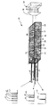
図3は、1つの実施例にしたがった本発明のWDM20の斜視図を示しており、この実施例は、ピグテールを有する4つのポートI1、I2、O1及びO2を含めて、完全に集積化された全パッケージを含む。指向性段25は、第1のウオークオフ要素(WO1)31、補償要素(Comp)32、第1のファラデー回転器(F1)33、第1の半波板(HWP1)34、第2のウオークオフ要素(WO2)35、第2のファラデー回転器(F2)36、及び第2の半波板(HWP2)37からなる。偏光段26は、偏光組合せ及び分離段からなり、この段は、例えば第3のウオークオフ要素(WO3)38であってもよい。
【0020】
図3は、波長λ1、λ2、λ3、λ4及びλ5のグループをこの例においてI1である1つの入力ポートから入力し、分散要素28によって分離し、かつ反射要素30によって反射する例であり、その際、いくつかの波長(λ1、λ3、λ4)は、分散要素28によってO1経路上に組合わされ、かつ出力ポートO1を通して出力され、かつ、いくつかの波長(λ2及びλ5)は、分散要素28によってO2経路上に組合わされ、かつ出力ポートO2を通して出力されている。
【0021】
図4にWDM20のスイッチ動作を達成するために互いに関連してこれらの部品が動作する原理を示す。図4は、それぞれの光経路21から24に対するそれぞれの部品31から38における偏光の様子を示している。ブロック21Aから21Iは、光経路I1に沿ってそれぞれの部品31から38及びLCセル30の偏光をそれぞれ示している。ブロック22Aから22Hは、光経路O1に沿ってそれぞれの部品31から38の偏光をそれぞれ示している。ブロック24Aから24Hは、光経路O2に沿ってそれぞれの部品31から38の偏光をそれぞれ示している。ブロック23Aから23Iは、光経路I2に沿ってそれぞれの部品31から38及びLCセル30の偏光をそれぞれ示している。
【0022】
入力ポートI1及びI2に侵入する光は、2つの直交する偏光成分に分解することができる偏光ベクトルを有する。同様に出力ポートO1及びO2から出る光は、2つの直交する偏光成分の組合せに対応する偏光ベクトルを有する。基本的にそれぞれの入力ポートに侵入するそれぞれの光信号の偏光ベクトルは、初めに2つの分離した直交偏光成分に分解され、特定の方向にウオークオフされ、かつ特定の方向に回転されるので、分散要素28を通過しかつ反射要素30に衝突する種々の波長のこれらのポートからの光信号は、反射され、組合わされ、かつ出力ポートO1、O2を通って、又は部分的にそれぞれの出力ポートO1及びO2を通って出力される。しかしながら装置は、入力ポートI1又はI2の1つからの光のうちいずれも又は実質的にいずれも入力ポートの1つに戻るように反射されないようになっている。
【0023】
各それぞれの信号の各それぞれの偏光ベクトルの偏光成分も、ブロック22A及び24Aにおいてプラス記号によって表示するように、出力ポートO1、O2から出る前に組合わされる。それ故に指向性段25のそれぞれの入力経路は、それぞれの偏光ベクトルを分離した偏光成分に分離し、かつこれらの偏光成分に所定の操作を行うが、指向性段25の出力経路は、それぞれの反射され分離された偏光成分に所定の操作を行い、かつそれぞれの偏光成分をそれぞれの偏光ベクトルに組合せる。
【0024】
波板34及び37は、水晶からなり、この水晶は、波板を製造するために典型的に利用される材料である。ウオークオフ要素31、35及び38は、例えばイットリウムバナジン酸塩から、又はルチル材料からなることができる。ウオークオフ結晶は、その結晶構造によって定義される偏光方向を有する。ファラデー回転器33及び36は、例えばざくろ石からなることができる。ファラデー回転器は、磁界の適用を介して光の偏光を回転する。ファラデー回転器は、保持機能をもつファラデー回転器であることができる。保持機能をもつファラデー回転器は、ファラデー回転器に加える磁界を除去した後も光を回転する機能を保持する。保持機能をもつファラデー回転器の代わりに、ファラデー回転器に隣接した又はこれにきわめて近接した集積化WDM装置20内に、必要な磁界を発生する磁石を埋め込んでもよい。
【0025】
これらの部品は、当該技術分野において周知であり、かつこれらが光信号の偏光ベクトルを偏光成分に分離し、かつ偏光成分に及ぼす作用は、米国特許第6088491号明細書及び米国特許第6026202号明細書に詳細に記載されている。その故にこれらの部品が必要な動作の詳細な説明は割愛する。
【0026】
初めに光ファイバからポートI1に侵入する光信号の偏光ベクトルは、ブロック21Aに小さな十字によって表示されたように、分離した直交成分に分離されていない。しかしながら入射された光信号が、WO1 31を通過した後に、光信号の水平偏光成分が分離され、かつブロック21Bによって表示するように、垂直偏光成分からウオークオフ方向に変位される。WO1 31は、WO1 31のウオークオフ方向に対して平行な光の偏光成分だけに(すなわちブロック31における水平な矢印によって表示されたウオークオフ方向に対して平行な水平偏光成分だけに)作用する。これにより、垂直に偏光された成分から水平に偏光された成分を分離しかつ変位する。したがってWO1 31のウオークオフ方向に対して平行な偏光を有する光は、WO1 31によって、WO1 31と同じ配向を有するビームに分離される。WO1 31のウオークオフ方向とは平行ではない偏光を有する光は、変位されないため初めの光ビームと一致しかつ変位されたビームの偏光に直交する偏光を有するビームのみが残ることになる。
【0027】
それからこれらのビームは、補償要素32を通過し、この補償要素は、ビームの偏光を変化しないが、ウオークオフ変位によって引起こされるあらゆる光経路長さの差を補償する。それから光は、第1のファラデー回転器F1 33を通過し、このファラデー回転器は、ブロック21Dにおける線によって表示するように、それぞれのビームの偏光の方向を45°だけ変化する。それから光は、第1の半波板HWP1 34を通過し、この半波板は、それぞれのビームの偏光を独立に回転し、これらのビームが、ブロック21Eによって表示するように、両方とも水平の偏光を有するようにする。HWP1部品34における破線は、部品のそれぞれの部分が偏光されたビームに別々に作用し、この部分は、ブロック21E、22D、23E及び24Dにおける表記からも明らかである。入力経路I1では偏光成分は水平なので、これらの偏光成分は第2のウオークオフ要素WO2
35を通過する際に影響を受けない。このウオークオフ要素WO2は、ブロック35における垂直な双方向矢印によって表示するように、垂直ウオークオフ方向の偏光成分のみウォークさせる。
【0028】
O1及びO2光経路に沿って逆方向に伝搬する光が、WO2 35によって空間的に変位されることに注意する。なぜならブロック22F、22E、24F及び24Eに示されたように、これらの経路に沿った光ビームは、これらのブロックにおける垂直な平行線、及びブロック22Fと22Eとの間及びブロック24Fと24Eとの間におけるこれらの線の垂直な変位によって表示するように、この点において垂直に偏光されているからである。指向性段25におけるI1とI2光経路に関するO1とO2光経路の方向におけるシフトは、図2Bに示す装置20の側面図から明らかである。
【0029】
それからI1光経路に沿って進行する光ビームは、第2のファラデー回転器F2 36を通過し、このファラデー回転器は、ブロック21Gに示すように、光ビームの偏光を45°だけ回転する。F2 36は、光経路O1及びO2に沿って進行する光に偏光を回転するように作用し、これらの偏光が、ブロック22G、22F、24G及び24Fにおける線によって表示するように、垂直になるように作用し、このFは、O1及びO2光経路偏光を、図2Bの側面図に示す指向性段25に示した方向にこれらの光経路を向け、WO2 35によって操作することを可能にする。
【0030】
それからI1に沿って進行する光ビームは、HWP2 37を通過し、このHWP2 37は、21Hにおける線によって表示するように、両方のビームの偏光を水平偏光に回転する。それからI1に沿って進行する光ビームは、偏光段26を通過する。この偏光段26はWO3ブロック38に相当する。WO3 38は、光ビームの方向を変化し、光経路I1に相当するビームが、図2Aの平面図に示した偏光段26において表示されたように、水平に変位されるようにする。水平の変位は、ブロック21Hにおける水平の線及びこのブロックの左上の隅からブロック21Iの右上の隅へのその移動によって示す。
【0031】
それからブロック21Iに示された偏光を有する光経路I1に相当する光ビームは、分散要素28を通過し、この分散要素は、光ビームにおけるすべての波長を空間的に分離する。光ビームの波長が空間的に分散されたとき、光ビームの偏光成分は、偏光成分と関連する波長に依存して、反射要素30の種々のピクセルに入射する。偏光成分が入射するピクセルが回転していないと、光経路I1に対応する光ビームは、そのピクセルにより反射され、かつ分散要素により組合わされ、これらの光ビームが、ビームを水平に変位するWO3 38を通過するようにする。偏光におけるこの水平のシフトは、ブロック22Hに示す位置へのブロック21Iにおける線の位置における水平のシフトによって表示される。それ故にこの場合、反射された光はO1光経路に侵入し、かつブロック22Hから22Aにおける線により表示されるように、指向性段25要素により操作される。
【0032】
垂直平面において、O1光経路はI1光経路に追従するが、図2Aの平面図に示すように、かつブロック22F及び22Eにおいて垂直方向における偏光成分のシフトによって表示されるように、WO2により横断平面においてその下にあることに注意する。WO1 31は、それぞれ光経路O1及びO2において進行する光の偏光成分を、これらがそれぞれ出力ポートO1及びO2を介して出力される直前に合成する。このことは、ブロック22B及び22A及び24B及び24Aにおける線によって表示されている。
【0033】
ブロック21Aにおける十字の位置に比較してブロック23Aにおける十字の異なった位置は、図2Aの平面図から明らかなように、入力光経路I1及びI2におけるビームの水平の分離を表示している。I2光経路に関して、水平偏光成分は、ブロック23Bにおける偏光表記線によって表示されるように、光がWO1 31を通過するときに、垂直偏光成分から分離される。I2光経路に対するブロック23Bから23Gにおける偏光の変化は、基本的にI1経路に対するそれぞれブロック21Bから21Gの変化と同じである。同様にO1光経路に対するブロック22Gから22Aにおける偏光の変化は、基本的にO2光経路に対するブロック24Gから24Aの変化と同じである。しかしながらHWP2 37は、光経路I1及びO1における光の偏光成分に作用とは異なった作用を光経路I2及びO2における光の偏光成分に及ぼす。それぞれブロック21H及び23Hによって表示されるように、HWP2 37は、光経路I1における光の偏光成分を、これらが水平であるように回転するが、一方光経路I2における光の偏光成分を、これらが垂直であるように回転する。
【0034】
この相違のため、反射要素30の対応するLCピクセルの偏光が回転しないとき、ブロック21I及び22Hによって表示されるように、I1光経路における反射された光は、光経路O1上に波長にしたがって分散要素28によって組合わされ、かつ同じ偏光を維持したまま、水平にシフトされる。偏光成分の水平のシフトは、WO3 38が水平ウオークオフ結晶であるためである。光経路I2に沿って進行する光に関して、反射要素30の対応するLCピクセルの偏光が回転しないとき、ブロック23I及び24Hによって表示されるように、反射された光は、光経路O2上に波長にしたがって分散要素28によって組合わされ、かつシフトされることなく、かつその垂直偏光を維持したまま、WO3 38を通過する。垂直偏光成分は、WO3 38が水平ウオークオフ結晶であるためシフトされない。これらの偏光に関して、反射されたI1光は、光経路O1だけに侵入し、かつ反射されたI2光は光経路O2だけに侵入することができる。それから反射された光は、それぞれの出力光経路に沿って指向性段25を通過し、かつそれぞれの出力ポートを介して集積化光WDM20から出る。
【0035】
反射要素30の対応するLCピクセルが完全に回転しているとき(すなわち90°だけの回転)、ブロック21Iによって表示される偏光を有する光経路I1における光は、ブロック24Hに示すように、分散要素28によって分散され、かつ回転したピクセルによって垂直偏光を有するように反射される。それからこの光は、影響を受けずにWO3 38を通過し、かつしたがってO2光経路に沿って伝搬するような状態にされるだけである。前記のように、偏光成分は、これらに結び付いた波長を有する。それ故に光経路I1から光経路O2への偏光成分の方向付けは、光経路I1から光経路O2へのこれらの偏光成分と関連する波長の方向付けと同じである。
【0036】
光経路I2に関して、反射要素30の対応するLCピクセルが完全に回転しているとき(すなわち90°だけの回転)、ブロック23Iによって表示された偏光を有する光経路I2上の光は、分散要素28によって分散され、かつブロック22Hによって示されるように、水平偏光を有するように、回転されたピクセルによって反射される。この光は、O1光経路に沿って伝搬するような条件にされるだけである。それ故に偏光成分に関連する波長にしたがって分散要素28によって合成されるとき、光経路O1に沿ってO1出力ポートに伝搬するだけである。前記のように、光経路I1から光経路O2に及び光経路I2から光経路O1に偏光成分を方向付けることは、これらの経路に沿ったこれらの偏光成分と関連する波長の方向付けと同じである。したがって反射要素のピクセルの状態を制御することによって、波長は、本発明のWDMによって選択的に分離取出すことができる。これにより波長は、選択的に分離して取出すことができ、かつ落とすことができ(例えばI1からO2へスイッチ)、又は加えることができる(例えばI1からの光のすべての波長がO1に達し、かつI2からの光の少なくともいくつかの波長がO1に達する)。もちろん本発明のWDMは、多くの別の目的のために使うことができる。例えばこれは、波長を分離して取出し、かつそれから出力ポートを介してこれらを捨てることによって、所定の波長の光を単純に減衰するために利用することができる。ここにおいて考慮された議論を考慮して、本発明のWDMが適した多くの目的は、当業者にとって明らかであろう。
【0037】
本発明の光WDM装置における別の実施例を、図5Aから図5Cを引用して説明する。図5Aは、種々の光学部品の構成及びこれらがWDM機能を実行するために光の偏光成分に及ぼす作用を示している。動作原理は図4を引用して前に説明したものと同じであるが、WDMの構成は図4の構成と異なっている。図5Bは、図5Aに示した部品の平面図、及び入力された光及び反射された光の偏光成分が光WDM装置を通って伝搬する様式を示している。図5Cは、図5Aに示した部品の側面図、及び入力された光及び反射された光の偏光成分が光WDM装置を通って伝搬する様子を示している。
【0038】
図5Aによれば、光WDM装置は、ウオークオフ(W/OFF)要素41、半波板(HWP)要素42、ウオークオン(W/ON)要素43、ファラデー回転器44、別のHWP要素45、ウオークオン(W/ON)要素46、分散要素47、及び反射要素50からなり、この反射要素は、望ましくは図4の実施例におけるように、選択的に制御可能なLCピクセルの配列である。ブロックは、4つの光ビームを示しており、これらの光ビームのそれぞれは、直交するように組合わされた2つの偏光成分を有する。光ビーム51及び52は、それぞれO1及びI1光経路に対応しており、光ビーム53及び54は、それぞれI2及びO2光経路に対応している。入射する光に対して、W/OFF要素41は、I1入力光に対応するビーム52の水平偏光成分52Aを、その垂直成分52Bから変位する。同様にW/OFF要素41は、I2入力光に対応するビーム53の水平偏光成分53Aを、その垂直成分53Bから変位する。光学装置からの出力光に対して、W/OFF要素41は、出力光経路O2に対応するビーム54の水平偏光成分54Aを、その垂直成分54Bと合成する。同様にW/OFF要素41は、出力光経路O1に対応するビーム51の水平偏光成分51Aを、その垂直成分51Bと合成する。偏光成分のこの分離及び合成は、図5Cのブロック41に見ることができる。
【0039】
HWP42は、箱の右側における分離した偏光成分だけに、すなわち偏光成分51A、52B、53A及び54Bだけに作用する。このことは図5Cにおけるブロック42からも明らかであり、このブロックにおいて偏光成分の半分だけが、HWP42を通って伝搬する。入射する光の分離した偏光成分52B及び53Aに対して、HWP42は、矢印に示すように時計方向の90°の回転を加える。出力光に対して、偏光成分51A及び53Aも、HWP42を進行する箱に示すように、W/OFF要素41の方向に伝搬してHWP42を通過するときに、時計方向に90°だけ回転される。それからW/OFF要素41は、2つのビームを形成するように、偏光成分51AとB及び54AとBを直交するように合成し、これら2つのビームそれぞれは、互いに直交する2つの偏光成分を有する。
【0040】
入力光に関して、偏光成分が、時計方向に90°だけ回転された後に、入力光は、W/ON要素43を通過する。この時に垂直に偏光されている入力光偏光成分53A及びBは、上方にシフトされる。このことは、図5Bのブロック43に示されたI2入力の垂直の傾斜から明らかである。I1入力の入力光偏光成分52A及びBは、図5Bにおけるブロック43を通過するまっすぐなI1線によって表示されるように、水平に偏光されたままであり、かつこれらがW/ON要素43を通って伝搬したときに影響を受けない。出力光に関して、W/ON要素43は、出力光O1の偏光成分51A及びBを下方にシフトするが、これらの偏光成分を垂直に偏光したままである。このシフトは、出力光の方向に関して図5Bのブロック43における上方への傾斜によって明らかである。出力光O2の偏光成分54A及びBは、図5Bにブロック43をまっすぐに通過するO2線によって表示されるように、水平に偏光されたままであり、W/ON要素43によって作用を受けない。
【0041】
ファラデー回転器44は、水平及び垂直に偏光された入力光偏光成分52AとB及び53AとBを、それぞれ45°だけ回転する。それからHWP45は、入力光偏光成分53AとB及び52AとBを、時計方向に45°だけ回転し、入力光偏光成分52AとBが垂直に偏光され、かつ入力光偏光成分53AとBが水平に偏光されるようにする。それからW/ON要素46は、垂直偏光された入力光偏光成分52A及び52Bを下方にシフトし、これらの偏光成分が、それぞれ水平に偏光された入力光偏光成分53AとBと空間的に一致し、かつこれらと直交するようにする。垂直に偏光された入力光偏光成分52A及び52Bの下方へのシフトは、入力光の伝搬方向に関して図5Bのブロック46における下方への傾斜によって表示される。
【0042】
反対方向において、垂直に偏光された反射光偏光成分51AとBは、水平に偏光された出力光偏光成分54AとBからこれらの偏光成分を分離するために、下方にシフトされる。反射要素50のLCピクセルが、偏光が回転されない状態にあるとき、入力光I1の空間的に分離された垂直偏光された入力光偏光成分52AとBは、同じ偏光によってピクセルにより反射され、この偏光は、入力光I2の入力光偏光成分53AとBの偏光に対して、かつ出力光O2の出力光偏光成分54AとBに対して直交している。それ故にポートI1から反射された光は、O1光経路を介して光学装置から外に伝搬するだけである。なぜならこの経路が、出力光偏光成分を適正に再分離しかつ再結合することができる唯一の光経路であるからである。分散要素47は、図4の説明で述べたように、入射光を波長にしたがって分離し、かつ反射された光を結合する。
【0043】
水平偏光された反射されたI2光は、O2光経路を介して光学装置から外に伝搬する。なぜならこの経路が、出力光偏光成分を適正に再分離しかつ再結合することができる唯一の光経路であるからである。他方において反射要素50の対応するピクセルが、偏光を90°だけ回転する状態にある場合、回転されたピクセルによって反射されたすべての光成分の偏光は、90°だけ回転される。それ故に入力光I1の垂直偏光された入力光偏光成分52AとBは、90°だけ回転され、これらの反射された光成分が、水平の偏光を有するようにする。この偏光によって、偏光成分は、これらが光経路O2を介して光学装置を通ってかつここから外に伝搬するときに、適正に再分離され、かつ再結合される。同様に水平偏光された入力光偏光成分53AとBの偏光は、90°だけ回転され、これらの偏光は、垂直に偏光されるようにする。この偏光によって、偏光成分は、これら偏光成分が光経路O1を介して光学装置を通ってかつここから外に伝搬されるときに、適正に再分離され、かつ再結合される。それ故に90°だけの反射要素50の対応するピクセルの偏光の角度の回転は、光学装置がWDMとして機能することを可能にする。なぜならこれは、波長にしたがって光を分離することができ、それぞれの偏光成分は、関連する波長を有し、かつ偏光成分のチャネルは、いずれかの入力ポートからいずれかの出力ポートへのいずれかの選ばれた波長に対応するからである。
【0044】
図4及び図5Aに示された実施例は2つの入力及び2つの出力を示しているとはいえ、本発明の光WDM装置が、1つだけの入力及び2つの出力を有することができることに注意する。望ましくはWDM装置は、2つの入力および2つの出力を有するので、二方向であり、かつ融通性をもって機能することができる。入力光偏光成分の空間的な分離は、入力光が光学装置に入力される前に行うことができる。
【0045】
当業者は、ここに提供された議論を考慮して、本発明の多くの可能な適用を理解するであろう。もちろん図4および図5Aに示したもの以外の波板及び結晶の配向は、集積化された形において本発明の目的を達成するために利用することができ、かつここに提供された議論を考慮して、当業者にとって理解することができる。また本発明は、本発明の集積化された光WDMの部品を創作するためにここに議論した材料に限定されるものではない。例えば前記のように、本発明の反射要素は、液晶セル以外のなんらかのものであることができ、かつ現在周知の又は将来発見され又は開発されるなんらかのものであることができる。
【0046】
本発明の特定の実施形態を説明し例示したが、本発明は説明し例示した特定の形態或いは部品配置に限定してはならない。本発明範囲は、ここに添付した特許請求の範囲ならびにそれらの均等物により規定されるべきである。しかしながら、本発明の広範な応用の参考に供するため、本発明の実施態様の一部を下記に掲げる。
【0047】
(実施態様1)
集積化された光波長分割多重(WDM)装置が、少なくとも1つの第1の入力ポート(I1)、第1の出力ポート(O1)及び第2の出力ポート(O2)を有し、
前記WDM装置は分散要素を含み、前記分散要素が複数の波長の光を受信し、前記光が偏光成分からなり、前記分散要素が前記波長に基づいて前記偏光成分を空間的に分離し、それぞれの偏光成分が関連する波長を有するとともに、
前記WDM装置は偏光制御反射器を含み、前記反射器が前記分散要素によって空間的に分離された偏光成分を受信するために複数の空間的に分離された偏光制御要素を有し、前記反射器が前記空間的に分離された偏光成分を反射する前記偏光制御要素の状態に依存する偏光の反射角において、前記空間的に分離された偏光成分を反射し、
前記WDM装置は前記第1の入力ポート(I1)を介して前記光WDM装置内に結合された偏光成分を受信しかつ偏光の特定の角度を有する前記入力偏光成分を供給するために前記入力偏光成分を操作する偏光依存光経路装置を含み、前記入力偏光成分が前記分散要素によって受信された前記光の前記偏光成分に相当し、前記入力偏光成分が、前記偏光制御要素の前記状態に依存する偏光の角度によって反射され、前記偏光制御要素のいずれか1つが、前記複数の状態のうちの第1の状態にあるとき、反射されるいずれかの偏光成分が、前記第1の出力ポート(O1)を介して出力され、かつ前記偏光制御要素のいずれか1つが、前記複数の状態のうちの第2の状態にあるとき、反射される前記偏光成分の少なくとも一部が、前記第2の出力ポート(O2)を介して出力される
ことを特徴とする、集積化された光波長分割多重(WDM)装置。
【0048】
(実施態様2)
前記偏光依存光経路装置が、入力偏光依存経路分割要素を含み、前記入力偏光依存経路分割要素が、前記入力偏光成分を空間的に分離した入力偏光成分に変換することを特徴とする、実施態様1に記載の光学装置。
【0049】
(実施態様3)
前記偏光依存光経路装置が、出力偏光依存経路分割要素を含み、前記偏光依存光経路装置からいずれかの偏光成分が出力される前に、前記偏光依存光経路装置が、前記反射された偏光成分を少なくとも一部を空間的に一致する出力偏光成分に変換することを特徴とする、実施態様3に記載の光WDM装置。
【0050】
(実施態様4)
前記反射器の前記偏光制御要素のいずれか1つが、前記複数の状態のうち第3の状態にあるとき、前記反射される偏光成分の少なくとも一部が前記第1の出力ポート(O1)を介して出力され、かつ前記反射される偏光成分の少なくとも一部が、前記第2の出力ポート(O2)を介して出力されることを特徴とする、実施態様3に記載の光WDM装置。
【0051】
(実施態様5)
前記複数の状態が、前記光WDM装置が、アナログ光WDM装置として機能するように状態の連続体を構成し、かつ、前記第1の出力ポート(O1)を介して出力される偏光成分の前記それぞれの部分、及び前記第2の出力ポート(O2)を介して出力される偏光成分の前記それぞれの部分が、前記状態の連続体から、前記反射器の前記偏光制御要素の前記状態を選択することによって制御可能に変化することができることを特徴とする、実施態様3に記載の光WDM装置。
【0052】
(実施態様6)
前記偏光依存光経路装置が、偏光依存結合器要素を含み、前記偏光依存結合器が、前記反射光偏光成分を少なくとも一部が空間的に一致する出力偏光成分に変換し、前記変換が前記偏光成分を前記出力ポートのいずれか(O1又はO2)から出力する前に行なわれることを特徴とする、実施態様3に記載の光学装置。
【0053】
(実施態様7)
前記光WDM装置が、さらに第2の入力ポート(I2)を含み、かつ、前記偏光依存光経路装置が、前記第1の入力ポート(I1)を介しかつ前記第2の入力ポート(I2)を介して前記光WDM装置内に結合された偏光成分を受信し、かつ偏光の特定の角度を有する前記入力偏光成分を供給するために前記入力偏光成分を操作し、前記入力偏光成分が前記分散要素によって受信された前記光の前記偏光成分に相当し、かつ、前記偏光制御要素のいずれか1つが、前記複数の状態のうち第1の状態にあるとき、前記反射器により反射されかつ前記第1の入力ポート(I1)を介して前記WDM装置内で合成されたいずれかの偏光成分が、前記第1の出力ポート(O1)を介して出力され、かつ前記反射器により反射されかつ前記第2の入力ポート(I2)を介して前記WDM装置内で合成されたいずれかの偏光成分が、前記第2の出力ポート(O2)を介して出力され、かつそ、前記偏光制御要素のいずれか1つが前記複数の状態のうち第2の状態にあるとき、前記反射器により反射されかつ前記第1の入力ポート(I1)を介して前記WDM装置内で合成されたいずれかの偏光成分が、前記第2の出力ポート(O2)を介して出力され、かつ前記反射器により反射されかつ前記第2の入力ポート(I2)を介して前記WDM装置内で合成されたいずれかの偏光成分が、前記第1の出力ポート(O1)を介して出力されることを特徴とする、実施態様3に記載の光学装置。
【0054】
(実施態様8)
前記偏光依存光経路装置が、入力偏光依存経路分割要素を含み、前記入力偏光依存経路分割要素が、前記入力偏光成分を空間的に分離された入力偏光成分に変換することを特徴とする、実施態様7に記載の光学装置。
【0055】
(実施態様9)
前記偏光依存光経路装置が、出力偏光依存経路分割要素を含み、かつ、前記偏光依存光経路装置からいずれかの偏光成分が出力される前に、前記偏光依存光経路装置が、前記反射された偏光成分の少なくとも一部が空間的に一致する出力偏光成分に変換することを特徴とする、実施態様8に記載の光WDM装置。
【0056】
(実施態様10)
前記反射器の前記偏光制御要素のいずれか1つが、前記複数の状態のうち第3の状態にあるとき、前記反射される偏光成分の少なくとも一部が前記第1の出力ポート(O1)を介して出力され、かつ前記反射される偏光成分の少なくとも一部が、前記第2の出力ポート(O2)を介して出力されることを特徴とする、実施態様9に記載の光WDM装置。
【0057】
(実施態様11)
前記複数の状態が、前記光WDM装置がアナログ光WDM装置として機能するようにし状態の連続体を構成し、かつ、前記第1の出力ポート(O1)を介して出力される偏光成分の前記それぞれの部分、及び前記第2の出力ポート(O2)を介して出力される偏光成分の前記それぞれの部分が、前記状態の連続体から、前記反射器の前記偏光制御要素の前記状態を選択することによって制御可能に変化することができることを特徴とする、実施態様9に記載の光WDM装置。
【0058】
(実施態様12)
前記偏光依存光経路装置が、偏光依存結合器要素を含み、前記偏光依存結合器が、前記反射光偏光成分の少なくとも一部が空間的に一致する出力偏光成分に変換し、前記変換が前記偏光成分を前記出力ポートのいずれか(O1又はO2)から出力する前に行なわれることを特徴とする、実施態様9に記載の光学装置。
【0059】
(実施態様13)
次のa)からe)のステップを含む光波長分割多重(WDM)装置によって光波長分割多重化を行なう方法。
a) 偏光依存光経路装置、分散要素、及びそれぞれ複数の状態を有する配列制御可能な反射要素を有する光WDM装置を設けるステップ。
b) 入力光を前記光WDM装置に結合するステップ。
c) 前記入力光を入力偏光成分に分離するために前記偏光依存光経路装置を利用し、それぞれの入力偏光成分が関連する波長を有するステップ。
d) 分散要素において前記入力偏光成分を受信し、かつ前記波長に基づいて前記入力光成分を空間的に分離するために前記分散要素を利用するステップ。
e) 前記配列制御可能な反射要素の前記制御可能な1つ又は複数の反射要素を前記複数の状態のうちの1つの状態に設定し、前記制御可能な反射要素が偏光の反射角によって入射する前記入力偏光成分を反射し、偏光の前記反射角が前記制御可能な反射要素の状態に依存し、前記偏光制御要素のいずれか1つが前記複数の状態のうち第1の状態にあるとき、反射されるいずれかの偏光成分が、前記第1の出力ポート(O1)を介して出力され、かつ、前記偏光制御要素のいずれか1つが、前記複数の状態のうち第2の状態にあるとき、1つ又は複数の反射される前記偏光成分の少なくとも一部が、前記第2の出力ポート(O2)を介して出力されるステップ。
【0060】
(実施態様14)
前記複数の状態が、前記光WDM装置がアナログ光WDM装置として機能するように状態の連続体を構成し、前記第1の出力ポート(O1)を介して出力される偏光成分の前記それぞれの部分、及び前記第2の出力ポート(O2)を介して出力される偏光成分の前記それぞれの部分が、前記状態の連続体から、前記反射器の前記偏光制御要素の前記状態を選択することによって制御可能に変化することができることを特徴とする、実施態様13に記載の方法。
【0061】
(実施態様15)
前記偏光依存光経路装置が、偏光依存結合器要素を含み、前記偏光依存結合器が、前記反射光偏光成分の少なくとも一部が空間的に一致する出力偏光成分に変換し、前記変換が前記偏光成分を前記出力ポートのいずれか(O1又はO2)から出力する前に行なわれることを特徴とする、実施態様13に記載の方法。
【0062】
(実施態様16)
前記光WDM装置が、さらに第2の入力ポート(I2)を含み、かつ、前記偏光依存光経路装置が、前記第1の入力ポート(I1)を介しかつ前記第2の入力ポート(I2)を介して前記光WDM装置内に結合された偏光成分を受信し、かつ偏光の特定の角度を有する前記入力偏光成分を供給するために前記入力偏光成分を操作し、前記入力偏光成分が、前記分散要素によって受信された前記光の前記偏光成分に相当し、かつ、前記偏光制御要素のいずれか1つが、前記複数の状態のうちの第1の状態にあるとき、前記反射器により反射されかつ前記第1の入力ポート(I1)を介して前記WDM装置内で合成されたいずれかの偏光成分が前記第1の出力ポート(O1)を介して出力され、かつ前記反射器により反射されかつ前記第2の入力ポート(I2)を介して前記WDM装置内で合成されたいずれかの偏光成分が、前記第2の出力ポート(O2)を介して出力され、かつ、前記偏光制御要素のいずれか1つが、前記複数の状態のうちの第2の状態にあるとき、前記反射器により反射されかつ前記第1の入力ポート(I1)を介して前記WDM装置内で合成されたいずれかの偏光成分が、前記第2の出力ポート(O2)を介して出力され、かつ前記反射器により反射されかつ前記第2の入力ポート(I2)を介して前記WDM装置内で合成されたいずれかの偏光成分が、前記第1の出力ポート(O1)を介して出力されることを特徴とする、実施態様13に記載の方法。
【図面の簡単な説明】
【図1】実施例による本発明の光学装置の概略的な線図である。
【図2】図1に示した本発明の光学装置の平面図及び側面図である。
【図3】特定の部品及び材料を利用して特定の様式で構成された本発明の光学装置の斜視図である。
【図4】図3に示した部品が波長分割多重化のための特定の偏光機能を実行する様式を示す偏光線図である。
【図5】別の実施例を示す装置構成図、偏光線図、平面図及び側面図である。
【符号の説明】
20 WDM装置
21 I1ポート
22 O1ポート
23 I2ポート
24 O2ポート
25 指向性段
26 偏光段
28 分散要素
30 反射要素[0001]
TECHNICAL FIELD OF THE INVENTION
The present invention relates to a wavelength division multiplexer (WDM), and more particularly to a reflective system and integrated optical WDM.
[0002]
[Prior art]
According to optical WDM, light of multiple wavelengths can be spatially dispersed such that each wavelength of light is spatially separated from all other wavelengths of light. WDM devices typically include two main functional parts. The first part provides the spatial demultiplexing (or dispersion) of the individual wavelengths through the use of a grating (eg, an arrayed wave guide grating, a filter array, etc.). The second part then acts on one or more spatially dispersed wavelengths, for example for attenuation, monitoring, compensation or switching.
[0003]
In a reflective system, these wavelengths are then returned via the same dispersive element, thereby multiplexing them again on one optical fiber (ie combining the wavelengths). Reflective WDM systems are increasingly being used in fiber optic networks due to their simplicity, small size, and low component count, as compared to transmissive WDM systems. However, the use of a reflective system requires the use of a circulator to separate the input and output signals. Circulators are often expensive and difficult to integrate into small optical systems. In addition, systems utilizing polarizing elements are more complex and require a separate circulator-like separation stage to route signals between the various ports. In addition to having a large number of parts, these types of systems are time consuming and expensive because they typically require precise alignment of some optical components.
[0004]
[Problems to be solved by the invention]
The present invention provides an optical WDM device that is smaller in size than known reflective WDM systems, has fewer components than known reflective WDM systems, does not require a circulator, and does not require alignment of optical components. is there.
[0005]
[Means for Solving the Problems]
The present invention provides an integrated reflected light WDM device that includes optical components integrated with each other to provide a reflective WDM device, which does not require any circulator, the device comprising The integrated features simplify alignment and are relatively low cost. WDM devices include integrated port separators, dispersive elements, and reflectors.
[0006]
The integrated port separator includes a variety of optical components that spatially separate the polarization components of the light beam input through the input ports of the integrated port separator. The spatially separated polarization components are output from an integrated port separator and input to a dispersive element. The dispersive elements are spatially separated by the wavelength associated with the polarization component. The spatially separated wavelengths are then input to the reflective element and reflected at a polarization angle that depends on the state of the reflective element. The reflected polarization components maintain their respective wavelengths when they are reflected. However, when they are reflected, these polarization components are directed along a path through an integrated port separator that depends on the angle of polarization of the reflected polarization components, which polarization depends on the state of the reflective element. I do.
[0007]
Desirably, the reflective element comprises an array of liquid crystal display (LCD) pixels, each of these pixels being individually controllable. Thus, the path of each polarization component through the integrated port separator depends on the state of the LCD pixel to which the polarization component is input, which state reflects the wavelength associated with each polarization component and the corresponding polarization component as a reflective element. Depends on the state in which the dispersive element leading to the spatial separation of wavelengths.
[0008]
The optical device can be used for a variety of purposes, such as, for example, a protection switch, an add / drop module, or any other application that requires or desires a wavelength polarization sensitive operation.
[0009]
BEST MODE FOR CARRYING OUT THE INVENTION
1 to 4 show a configuration of an integrated optical WDM according to an embodiment of the present invention. FIG. 1 shows a schematic diagram of an
[0010]
Each
[0011]
The
[0012]
For input beams I1 and I2 propagating through
[0013]
[0014]
In a preferred embodiment, the polarization component is output via the O1 path if the LC pixel to which the polarization component from the I1 path enters is not rotating. Conversely, if the LC pixel to which the polarization component from the I1 path is rotated by 90 °, the polarization component is output via the O2 path. Similarly, if the LC pixel to which the polarization component from the I2 path is input is not rotating, the polarization component is output via the O2 path. Conversely, if the pixel to which the polarization component from the I2 path is rotated by 90 °, the polarization component is output via the O1 path.
[0015]
Outputting the reflected polarization component along a particular path means outputting the wavelength associated with the reflected polarization component along a particular path since the reflected polarization component has an associated wavelength. Is the same as For example, the optical input at I1 includes certain wavelengths that need to be output via output path O2 (ie, is removed or removed at certain locations in the network), and other wavelengths need to continue in the forward direction. Is present (ie, through output path O2), certain pixels of
[0016]
To implement the
[0017]
A plan view and a side view of the integrated
[0018]
In FIG. 2B, light paths I1 and I2 are in the same transverse plane over the course of these light paths through
[0019]
FIG. 3 shows a perspective view of a
[0020]
FIG. 3 shows an example in which a group of wavelengths λ1, λ2, λ3, λ4 and λ5 is input from one input port, which is I1 in this example, separated by a
[0021]
FIG. 4 illustrates the principle by which these components operate in relation to each other to achieve the switch operation of
[0022]
Light entering the input ports I1 and I2 has a polarization vector that can be decomposed into two orthogonal polarization components. Similarly, light exiting output ports O1 and O2 has a polarization vector corresponding to a combination of two orthogonal polarization components. Basically, the polarization vector of each optical signal entering each input port is first decomposed into two separate orthogonal polarization components, walked off in a particular direction, and rotated in a particular direction, Optical signals from these ports of various wavelengths passing through the
[0023]
The polarization components of each respective polarization vector of each respective signal are also combined before exiting output ports O1, O2, as indicated by the plus sign in
[0024]
The
[0025]
These components are well known in the art and their effect on separating the polarization vector of an optical signal into polarization components and on the polarization components is described in US Pat. No. 6,088,491 and US Pat. It is described in detail in the book. Therefore, a detailed description of the operation required for these components is omitted.
[0026]
The polarization vector of the optical signal that initially enters the port I1 from the optical fiber is not separated into separate orthogonal components, as indicated by the small cross in
[0027]
The beams then pass through a compensating
Unaffected when passing through 35. This walk-off element WO2 walks only the polarization component in the vertical walk-off direction, as indicated by the vertical two-way arrow in
[0028]
Note that light propagating in the opposite direction along the O1 and O2 optical paths is spatially displaced by
[0029]
The light beam traveling along the I1 light path then passes through a second Faraday rotator F236, which rotates the polarization of the light beam by 45 °, as shown in
[0030]
The light beam traveling along I1 then passes through
[0031]
The light beam corresponding to the light path I1 with the polarization shown in block 21I then passes through a
[0032]
In the vertical plane, the O1 light path follows the I1 light path, but is traversed by WO2 as shown in the plan view of FIG. 2A and as indicated by the shift of the polarization component in the vertical direction in
[0033]
The different positions of the cross in
[0034]
Due to this difference, when the polarization of the corresponding LC pixel of the
[0035]
When the corresponding LC pixel of the
[0036]
With respect to light path I2, when the corresponding LC pixel of
[0037]
Another embodiment of the optical WDM apparatus according to the present invention will be described with reference to FIGS. 5A to 5C. FIG. 5A illustrates the configuration of various optical components and their effect on the polarization components of light to perform a WDM function. The principle of operation is the same as that described above with reference to FIG. 4, but the configuration of the WDM is different from that of FIG. FIG. 5B shows a plan view of the component shown in FIG. 5A and the manner in which the polarization components of the input and reflected light propagate through the optical WDM device. FIG. 5C shows a side view of the component shown in FIG. 5A and how the polarization components of the input and reflected light propagate through the optical WDM device.
[0038]
According to FIG. 5A, an optical WDM device includes a walk-off (W / OFF)
[0039]
The
[0040]
For the input light, the input light passes through the W /
[0041]
The
[0042]
In the opposite direction, the vertically polarized reflected
[0043]
The horizontally polarized reflected I2 light propagates out of the optical device via the O2 light path. This is because this is the only light path that can properly re-separate and recombine the output light polarization components. On the other hand, if the corresponding pixel of the
[0044]
Although the embodiments shown in FIGS. 4 and 5A show two inputs and two outputs, the optical WDM device of the present invention can have only one input and two outputs. warn. Desirably, the WDM device has two inputs and two outputs, so that it can be bidirectional and function flexibly. Spatial separation of the input light polarization components can be performed before the input light is input to the optical device.
[0045]
One skilled in the art will appreciate the many possible applications of the present invention in light of the discussion provided herein. Of course, corrugations and crystal orientations other than those shown in FIGS. 4 and 5A can be utilized to achieve the objectives of the present invention in integrated form and take into account the discussion provided herein. Then, it can be understood by those skilled in the art. Also, the present invention is not limited to the materials discussed herein for creating the integrated optical WDM components of the present invention. For example, as described above, the reflective element of the present invention can be something other than a liquid crystal cell, and can be something now known or discovered or developed in the future.
[0046]
Although particular embodiments of the present invention have been described and illustrated, the invention should not be limited to the particular forms or component arrangements described and illustrated. It is intended that the scope of the invention be defined by the Claims appended hereto and their equivalents. However, some of the embodiments of the present invention are set forth below to provide a reference for a wide range of applications of the present invention.
[0047]
(Embodiment 1)
An integrated optical wavelength division multiplexing (WDM) device has at least a first input port (I1), a first output port (O1), and a second output port (O2);
The WDM device includes a dispersive element, the dispersive element receives light of a plurality of wavelengths, the light comprises a polarization component, and the dispersion element spatially separates the polarization component based on the wavelength, And the polarization components have an associated wavelength,
The WDM device includes a polarization control reflector, the reflector having a plurality of spatially separated polarization control elements for receiving a polarization component spatially separated by the dispersive element, Reflects the spatially separated polarization component at a reflection angle of polarized light that depends on the state of the polarization control element that reflects the spatially separated polarization component,
The WDM device receives a polarization component coupled into the optical WDM device via the first input port (I1) and provides the input polarization component to provide the input polarization component having a particular angle of polarization. A polarization dependent light path device for manipulating the component, wherein the input polarization component corresponds to the polarization component of the light received by the dispersive element, and the input polarization component depends on the state of the polarization control element. When any one of the polarization control elements is reflected by an angle of polarization and any one of the polarization control elements is in a first state of the plurality of states, any reflected polarization component is reflected by the first output port (O1). ), And when any one of the polarization control elements is in a second of the plurality of states, at least a portion of the reflected polarization component is coupled to the second output. It is outputted through the over preparative (O2)
An integrated optical wavelength division multiplexing (WDM) device.
[0048]
(Embodiment 2)
An embodiment wherein the polarization dependent optical path device includes an input polarization dependent path splitting element, wherein the input polarization dependent path splitting element converts the input polarization component into a spatially separated input polarization component. 2. The optical device according to 1.
[0049]
(Embodiment 3)
The polarization-dependent light path device includes an output polarization-dependent path splitting element, and the polarization-dependent light path device is configured to generate the reflected polarization component before any polarization component is output from the polarization-dependent light path device. The optical WDM apparatus according to
[0050]
(Embodiment 4)
When any one of the polarization control elements of the reflector is in a third of the plurality of states, at least a portion of the reflected polarization component is coupled through the first output port (O1). The optical WDM apparatus according to
[0051]
(Embodiment 5)
The plurality of states constitute a continuum of states so that the optical WDM device functions as an analog optical WDM device, and the polarization component output through the first output port (O1). A respective portion and the respective portion of the polarization component output via the second output port (O2) select the state of the polarization control element of the reflector from the continuum of states. The optical WDM apparatus according to the third embodiment, wherein the optical WDM apparatus can be controllably changed.
[0052]
(Embodiment 6)
The polarization-dependent light path device includes a polarization-dependent coupler element, wherein the polarization-dependent coupler converts the reflected light polarization component into an output polarization component that is at least partially spatially coincident, wherein the conversion is the polarization. The optical device according to
[0053]
(Embodiment 7)
The optical WDM device further includes a second input port (I2), and the polarization-dependent optical path device is connected to the second input port (I2) via the first input port (I1). Receiving the polarization component coupled into the optical WDM apparatus via the optical WDM device, and manipulating the input polarization component to provide the input polarization component having a particular angle of polarization, wherein the input polarization component is the dispersion element. Corresponding to the polarization component of the light received by the light source, and when any one of the polarization control elements is in a first state of the plurality of states, is reflected by the reflector and the first Any of the polarization components synthesized in the WDM device through the input port (I1) is output through the first output port (O1), is reflected by the reflector, and is Input port Any one of the polarization components synthesized in the WDM device through the port (I2) is output through the second output port (O2), and one of the polarization control elements is When in the second state of the plurality of states, any of the polarized light components reflected by the reflector and combined in the WDM device via the first input port (I1) is transmitted to the second state. Any of the polarization components output through the output port (O2) of the first optical device and reflected by the reflector and combined in the WDM device through the second input port (I2) is converted into the first polarization component. The optical device according to the third embodiment, wherein the light is output through the output port (O1).
[0054]
(Embodiment 8)
The implementation wherein the polarization dependent optical path device includes an input polarization dependent path splitting element, the input polarization dependent path splitting element converting the input polarization component into a spatially separated input polarization component. The optical device according to aspect 7.
[0055]
(Embodiment 9)
The polarization dependent light path device includes an output polarization dependent path splitting element, and before any polarization component is output from the polarization dependent light path device, the polarization dependent light path device is the reflected light component. The optical WDM apparatus according to embodiment 8, wherein at least a part of the polarization component is converted into an output polarization component that spatially matches.
[0056]
(Embodiment 10)
When any one of the polarization control elements of the reflector is in a third of the plurality of states, at least a portion of the reflected polarization component is coupled through the first output port (O1). The optical WDM device according to embodiment 9, wherein at least a part of the polarized light component output and reflected is output via the second output port (O2).
[0057]
(Embodiment 11)
The plurality of states configure the optical WDM apparatus to function as an analog optical WDM apparatus to form a continuum of states, and each of the polarization components output via the first output port (O1). And the respective portions of the polarization component output via the second output port (O2) select the state of the polarization control element of the reflector from the continuum of states. The optical WDM apparatus according to embodiment 9, wherein the optical WDM apparatus can be controllably changed by the control.
[0058]
(Embodiment 12)
The polarization-dependent light path device includes a polarization-dependent coupler element, wherein the polarization-dependent coupler converts the reflected light polarization component into an output polarization component in which at least a portion of the reflected light polarization component is spatially matched, wherein the conversion is the polarization. The optical device according to embodiment 9, wherein the conversion is performed before outputting a component from any of the output ports (O1 or O2).
[0059]
(Embodiment 13)
A method for performing optical wavelength division multiplexing by an optical wavelength division multiplexing (WDM) device including the following steps a) to e).
a) Providing an optical WDM device having a polarization dependent optical path device, a dispersive element, and an array controllable reflective element each having a plurality of states.
b) coupling input light to the optical WDM device.
c) utilizing the polarization dependent optical path device to separate the input light into input polarization components, each input polarization component having an associated wavelength.
d) receiving the input polarization component at a dispersive element and utilizing the dispersive element to spatially separate the input light component based on the wavelength.
e) setting said one or more controllable reflective elements of said array controllable reflective element to one of said plurality of states, said controllable reflective element being incident by a reflection angle of polarized light; Reflecting the input polarization component, wherein the angle of reflection of the polarized light depends on the state of the controllable reflective element, and when any one of the polarization control elements is in a first state of the plurality of states, When any one of the polarization components is output through the first output port (O1) and any one of the polarization control elements is in a second state of the plurality of states, Outputting at least a portion of one or more of the reflected polarization components through the second output port (O2).
[0060]
(Embodiment 14)
The plurality of states constitute a continuum of states such that the optical WDM device functions as an analog optical WDM device, and the respective portions of the polarization component output via the first output port (O1). And the respective portion of the polarization component output via the second output port (O2) is controlled by selecting the state of the polarization control element of the reflector from the continuum of states. 14. Method according to embodiment 13, characterized in that it can be varied as possible.
[0061]
(Embodiment 15)
The polarization-dependent light path device includes a polarization-dependent coupler element, wherein the polarization-dependent coupler converts the reflected light polarization component into an output polarization component in which at least a portion of the reflected light polarization component is spatially matched, wherein the conversion is the polarization. 14. The method according to embodiment 13, wherein the method is performed before outputting a component from any of the output ports (O1 or O2).
[0062]
(Embodiment 16)
The optical WDM device further includes a second input port (I2), and the polarization-dependent optical path device is connected to the second input port (I2) via the first input port (I1). Receiving the polarization component coupled into the optical WDM device via the optical WDM device and manipulating the input polarization component to provide the input polarization component having a particular angle of polarization, wherein the input polarization component is Correspond to the polarization component of the light received by the element, and when any one of the polarization control elements is in a first state of the plurality of states, is reflected by the reflector and Any of the polarization components combined in the WDM device via a first input port (I1) is output via the first output port (O1) and is reflected by the reflector and the
[Brief description of the drawings]
FIG. 1 is a schematic diagram of an optical device of the present invention according to an embodiment.
FIG. 2 is a plan view and a side view of the optical device of the present invention shown in FIG.
FIG. 3 is a perspective view of an optical device of the present invention configured in a particular manner utilizing certain components and materials.
FIG. 4 is a polarization diagram illustrating the manner in which the components shown in FIG. 3 perform a particular polarization function for wavelength division multiplexing.
FIG. 5 is an apparatus configuration diagram, a polarization diagram, a plan view, and a side view showing another embodiment.
[Explanation of symbols]
20 WDM device
21 I1 port
22 O1 port
23 I2 port
24 O2 port
25 Directivity stage
26 polarization stage
28 Distributed Elements
30 reflective elements
Claims (16)
前記WDM装置は分散要素を含み、前記分散要素が複数の波長の光を受信し、前記光が偏光成分からなり、前記分散要素が前記波長に基づいて前記偏光成分を空間的に分離し、それぞれの偏光成分が関連する波長を有するとともに、
前記WDM装置は偏光制御反射器を含み、前記反射器が前記分散要素によって空間的に分離された偏光成分を受信するために複数の空間的に分離された偏光制御要素を有し、前記反射器が前記空間的に分離された偏光成分を反射する前記偏光制御要素の状態に依存する偏光の反射角において、前記空間的に分離された偏光成分を反射し、
前記WDM装置は前記第1の入力ポート(I1)を介して前記光WDM装置内に結合された偏光成分を受信しかつ偏光の特定の角度を有する前記入力偏光成分を供給するために前記入力偏光成分を操作する偏光依存光経路装置を含み、前記入力偏光成分が前記分散要素によって受信された前記光の前記偏光成分に相当し、前記入力偏光成分が、前記偏光制御要素の前記状態に依存する偏光の角度によって反射され、前記偏光制御要素のいずれか1つが、前記複数の状態のうちの第1の状態にあるとき、反射されるいずれかの偏光成分が、前記第1の出力ポート(O1)を介して出力され、かつ前記偏光制御要素のいずれか1つが、前記複数の状態のうちの第2の状態にあるとき、反射される前記偏光成分の少なくとも一部が、前記第2の出力ポート(O2)を介して出力される
ことを特徴とする、集積化された光波長分割多重(WDM)装置。An integrated optical wavelength division multiplexing (WDM) device has at least a first input port (I1), a first output port (O1), and a second output port (O2);
The WDM device includes a dispersive element, the dispersive element receives light of a plurality of wavelengths, the light comprises a polarization component, and the dispersion element spatially separates the polarization component based on the wavelength, And the polarization components have an associated wavelength,
The WDM device includes a polarization control reflector, the reflector having a plurality of spatially separated polarization control elements for receiving a polarization component spatially separated by the dispersive element, Reflects the spatially separated polarization component at a reflection angle of polarized light that depends on the state of the polarization control element that reflects the spatially separated polarization component,
The WDM device receives a polarization component coupled into the optical WDM device via the first input port (I1) and provides the input polarization component to provide the input polarization component having a particular angle of polarization. A polarization dependent light path device for manipulating the component, wherein the input polarization component corresponds to the polarization component of the light received by the dispersive element, and the input polarization component depends on the state of the polarization control element. When any one of the polarization control elements is reflected by an angle of polarization and any one of the polarization control elements is in a first state of the plurality of states, any reflected polarization component is reflected by the first output port (O1). ), And when any one of the polarization control elements is in a second of the plurality of states, at least a portion of the reflected polarization component is coupled to the second output. Characterized in that it is outputted through the over preparative (O2), integrated optical wavelength division multiplexing (WDM) device.
a) 偏光依存光経路装置、分散要素、及びそれぞれ複数の状態を有する配列制御可能な反射要素を有する光WDM装置を設けるステップ。
b) 入力光を前記光WDM装置に結合するステップ。
c) 前記入力光を入力偏光成分に分離するために前記偏光依存光経路装置を利用し、それぞれの入力偏光成分が関連する波長を有するステップ。
d) 分散要素において前記入力偏光成分を受信し、かつ前記波長に基づいて前記入力光成分を空間的に分離するために前記分散要素を利用するステップ。
e) 前記配列制御可能な反射要素の前記制御可能な1つ又は複数の反射要素を前記複数の状態のうちの1つの状態に設定し、前記制御可能な反射要素が偏光の反射角によって入射する前記入力偏光成分を反射し、偏光の前記反射角が前記制御可能な反射要素の状態に依存し、前記偏光制御要素のいずれか1つが前記複数の状態のうち第1の状態にあるとき、反射されるいずれかの偏光成分が、前記第1の出力ポート(O1)を介して出力され、かつ、前記偏光制御要素のいずれか1つが、前記複数の状態のうち第2の状態にあるとき、1つ又は複数の反射される前記偏光成分の少なくとも一部が、前記第2の出力ポート(O2)を介して出力されるステップ。A method for performing optical wavelength division multiplexing by an optical wavelength division multiplexing (WDM) device including the following steps a) to e).
a) Providing an optical WDM device having a polarization dependent optical path device, a dispersive element, and an array controllable reflective element each having a plurality of states.
b) coupling input light to the optical WDM device.
c) utilizing the polarization dependent optical path device to separate the input light into input polarization components, each input polarization component having an associated wavelength.
d) receiving the input polarization component at a dispersive element and utilizing the dispersive element to spatially separate the input light component based on the wavelength.
e) setting said one or more controllable reflective elements of said array controllable reflective element to one of said plurality of states, said controllable reflective element being incident by a reflection angle of polarized light; Reflecting the input polarization component, wherein the angle of reflection of the polarized light depends on the state of the controllable reflective element, and when any one of the polarization control elements is in a first state of the plurality of states, When any one of the polarization components is output through the first output port (O1) and any one of the polarization control elements is in a second state of the plurality of states, Outputting at least a portion of one or more of the reflected polarization components through the second output port (O2).
Applications Claiming Priority (1)
| Application Number | Priority Date | Filing Date | Title |
|---|---|---|---|
| US10/098,244 US6690854B2 (en) | 2002-03-15 | 2002-03-15 | Optical wavelength division multiplexer |
Publications (2)
| Publication Number | Publication Date |
|---|---|
| JP2004029722A true JP2004029722A (en) | 2004-01-29 |
| JP2004029722A5 JP2004029722A5 (en) | 2006-04-20 |
Family
ID=27765429
Family Applications (1)
| Application Number | Title | Priority Date | Filing Date |
|---|---|---|---|
| JP2003055063A Withdrawn JP2004029722A (en) | 2002-03-15 | 2003-03-03 | Optical wavelength division multiplexer |
Country Status (3)
| Country | Link |
|---|---|
| US (1) | US6690854B2 (en) |
| EP (1) | EP1345053A3 (en) |
| JP (1) | JP2004029722A (en) |
Families Citing this family (42)
| Publication number | Priority date | Publication date | Assignee | Title |
|---|---|---|---|---|
| WO2015081806A1 (en) * | 2013-12-04 | 2015-06-11 | 匠研光学科技(上海)有限公司 | Wavelength-independent and temperature-independent faraday rotating mirror |
| US9760953B1 (en) | 2014-03-12 | 2017-09-12 | Intuit Inc. | Computer implemented methods systems and articles of manufacture for identifying tax return preparation application questions based on semantic dependency |
| US10915970B1 (en) | 2014-03-12 | 2021-02-09 | Intuit Inc. | Computer implemented methods systems and articles of manufacture for communicating and resolving electronic tax return errors and inconsistent data |
| US10387969B1 (en) | 2014-03-12 | 2019-08-20 | Intuit Inc. | Computer implemented methods systems and articles of manufacture for suggestion-based interview engine for tax return preparation application |
| US10867355B1 (en) | 2014-07-31 | 2020-12-15 | Intuit Inc. | Computer implemented methods systems and articles of manufacture for preparing electronic tax return with assumption data |
| US11430072B1 (en) | 2014-07-31 | 2022-08-30 | Intuit Inc. | System and method of generating estimates used to calculate taxes |
| US9916628B1 (en) | 2014-07-31 | 2018-03-13 | Intuit Inc. | Interview question modification during preparation of electronic tax return |
| US10540725B1 (en) | 2014-08-18 | 2020-01-21 | Intuit Inc. | Methods systems and articles of manufacture for handling non-standard screen changes in preparing an electronic tax return |
| US10977743B1 (en) | 2014-08-18 | 2021-04-13 | Intuit Inc. | Computer implemented methods systems and articles of manufacture for instance and suggestion differentiation during preparation of electronic tax return |
| US10970793B1 (en) | 2014-08-18 | 2021-04-06 | Intuit Inc. | Methods systems and articles of manufacture for tailoring a user experience in preparing an electronic tax return |
| US11861734B1 (en) | 2014-08-18 | 2024-01-02 | Intuit Inc. | Methods systems and articles of manufacture for efficiently calculating a tax return in a tax return preparation application |
| US10169826B1 (en) | 2014-10-31 | 2019-01-01 | Intuit Inc. | System and method for generating explanations for tax calculations |
| US9922376B1 (en) | 2014-10-31 | 2018-03-20 | Intuit Inc. | Systems and methods for determining impact chains from a tax calculation graph of a tax preparation system |
| US10796381B1 (en) | 2014-10-31 | 2020-10-06 | Intuit Inc. | Systems and methods for determining impact correlations from a tax calculation graph of a tax preparation system |
| US10387970B1 (en) | 2014-11-25 | 2019-08-20 | Intuit Inc. | Systems and methods for analyzing and generating explanations for changes in tax return results |
| US10296984B1 (en) | 2014-11-26 | 2019-05-21 | Intuit Inc. | Systems, methods and articles of manufacture for determining relevancy of tax topics in a tax preparation system |
| US10235722B1 (en) | 2014-11-26 | 2019-03-19 | Intuit Inc. | Systems and methods for analyzing and determining estimated taxes |
| US10235721B1 (en) | 2014-11-26 | 2019-03-19 | Intuit Inc. | System and method for automated data gathering for tax preparation |
| US11222384B1 (en) | 2014-11-26 | 2022-01-11 | Intuit Inc. | System and method for automated data estimation for tax preparation |
| US10157426B1 (en) | 2014-11-28 | 2018-12-18 | Intuit Inc. | Dynamic pagination of tax return questions during preparation of electronic tax return |
| US10572952B1 (en) | 2014-12-01 | 2020-02-25 | Intuit Inc. | Computer implemented methods systems and articles of manufacture for cross-field validation during preparation of electronic tax return |
| US10796382B1 (en) | 2015-03-30 | 2020-10-06 | Intuit Inc. | Computer-implemented method for generating a customized tax preparation experience |
| US10872384B1 (en) | 2015-03-30 | 2020-12-22 | Intuit Inc. | System and method for generating explanations for year-over-year tax changes |
| US10140666B1 (en) | 2015-03-30 | 2018-11-27 | Intuit Inc. | System and method for targeted data gathering for tax preparation |
| US9990678B1 (en) | 2015-03-31 | 2018-06-05 | Intuit Inc. | Systems methods and articles of manufacture for assessing trustworthiness of electronic tax return data |
| US11113771B1 (en) | 2015-04-28 | 2021-09-07 | Intuit Inc. | Systems, methods and articles for generating sub-graphs of a tax calculation graph of a tax preparation system |
| US10685407B1 (en) | 2015-04-30 | 2020-06-16 | Intuit Inc. | Computer-implemented methods, systems and articles of manufacture for tax topic prediction utilizing prior tax returns |
| US10664924B1 (en) | 2015-04-30 | 2020-05-26 | Intuit Inc. | Computer-implemented methods, systems and articles of manufacture for processing sensitive electronic tax return data |
| US10664925B2 (en) | 2015-06-30 | 2020-05-26 | Intuit Inc. | Systems, methods and articles for determining tax recommendations |
| US10607298B1 (en) | 2015-07-30 | 2020-03-31 | Intuit Inc. | System and method for indicating sections of electronic tax forms for which narrative explanations can be presented |
| US10402913B2 (en) | 2015-07-30 | 2019-09-03 | Intuit Inc. | Generation of personalized and hybrid responses to queries submitted from within tax return preparation system during preparation of electronic tax return |
| US11176620B1 (en) | 2016-06-28 | 2021-11-16 | Intuit Inc. | Systems and methods for generating an error report listing errors in the preparation of a payroll tax form |
| US10796231B2 (en) | 2016-07-26 | 2020-10-06 | Intuit Inc. | Computer-implemented systems and methods for preparing compliance forms to meet regulatory requirements |
| US10769592B1 (en) | 2016-07-27 | 2020-09-08 | Intuit Inc. | Methods, systems and computer program products for generating explanations for a benefit qualification change |
| US10872315B1 (en) | 2016-07-27 | 2020-12-22 | Intuit Inc. | Methods, systems and computer program products for prioritization of benefit qualification questions |
| US11087411B2 (en) | 2016-07-27 | 2021-08-10 | Intuit Inc. | Computerized tax return preparation system and computer generated user interfaces for tax topic completion status modifications |
| US11055794B1 (en) | 2016-07-27 | 2021-07-06 | Intuit Inc. | Methods, systems and computer program products for estimating likelihood of qualifying for benefit |
| US10762472B1 (en) | 2016-07-27 | 2020-09-01 | Intuit Inc. | Methods, systems and computer program products for generating notifications of benefit qualification change |
| US10664926B2 (en) | 2016-10-26 | 2020-05-26 | Intuit Inc. | Methods, systems and computer program products for generating and presenting explanations for tax questions |
| US11138676B2 (en) | 2016-11-29 | 2021-10-05 | Intuit Inc. | Methods, systems and computer program products for collecting tax data |
| US10367596B1 (en) * | 2017-05-23 | 2019-07-30 | Ii-Vi Delaware, Inc. | Multiple wavelength selective switch with shared switch |
| CN114325950B (en) * | 2021-12-10 | 2024-03-26 | 江苏永鼎光电子技术有限公司 | High-performance 100G dense wavelength division multiplexing device |
Family Cites Families (4)
| Publication number | Priority date | Publication date | Assignee | Title |
|---|---|---|---|---|
| US6327019B1 (en) * | 1997-02-07 | 2001-12-04 | Tellium, Inc. | Dual liquid-crystal wavelength-selective optical switch |
| US6026202A (en) * | 1997-02-25 | 2000-02-15 | Hewlett-Packard Company | Compact, low crosstalk, three-port optical circulator |
| US6088491A (en) * | 1998-02-13 | 2000-07-11 | Agilent Technologies, Inc. | Optical circulator |
| US20010048556A1 (en) * | 1999-11-29 | 2001-12-06 | Ranalli Eliseo R. | Wavelength selective switch |
-
2002
- 2002-03-15 US US10/098,244 patent/US6690854B2/en not_active Expired - Lifetime
- 2002-11-06 EP EP02024742A patent/EP1345053A3/en not_active Withdrawn
-
2003
- 2003-03-03 JP JP2003055063A patent/JP2004029722A/en not_active Withdrawn
Also Published As
| Publication number | Publication date |
|---|---|
| US20030174936A1 (en) | 2003-09-18 |
| EP1345053A3 (en) | 2004-06-23 |
| EP1345053A2 (en) | 2003-09-17 |
| US6690854B2 (en) | 2004-02-10 |
Similar Documents
| Publication | Publication Date | Title |
|---|---|---|
| JP2004029722A (en) | Optical wavelength division multiplexer | |
| US8731403B2 (en) | Multicast optical switch | |
| US7787720B2 (en) | Wavelength selective reconfigurable optical cross-connect | |
| US10495819B2 (en) | Optical arrangement for managing diversity and isolation between ports in a wavelength selective switch | |
| US10267994B2 (en) | Wavelength selective switch including a liquid crystal on silicon | |
| EP2639611B1 (en) | Wavelength selective switch | |
| JP5373291B2 (en) | Wavelength selective switch | |
| US7092594B2 (en) | Wavelength selector switch | |
| JP2000162546A (en) | Photonics system | |
| JP2020514797A (en) | Optical arrangement for suppressing out-of-band crosstalk in wavelength selective switches | |
| US9521474B2 (en) | Wavelength selective switch having multi-layer reflector | |
| US20080219663A1 (en) | Optical device with cascaded steering devices | |
| JP5651904B2 (en) | N × N wavelength selective switch | |
| JP2005115377A (en) | Device and method for wavelength-selective switching selectively transmitting optical signal according to wavelength | |
| US10254625B2 (en) | Optical signal processing device | |
| WO2004008208A1 (en) | Wavelength selective switch | |
| JP4544828B2 (en) | Wavelength selective switch | |
| JP5839586B2 (en) | Optical signal processor | |
| WO2019203307A1 (en) | Wavelength-selective optical switch | |
| US7079319B2 (en) | Optical signal control device and method for utilizing same | |
| JP2005106936A (en) | Semiconductor optical module |
Legal Events
| Date | Code | Title | Description |
|---|---|---|---|
| A521 | Written amendment |
Free format text: JAPANESE INTERMEDIATE CODE: A821 Effective date: 20051005 |
|
| RD02 | Notification of acceptance of power of attorney |
Free format text: JAPANESE INTERMEDIATE CODE: A7422 Effective date: 20051005 |
|
| A521 | Written amendment |
Free format text: JAPANESE INTERMEDIATE CODE: A523 Effective date: 20060302 |
|
| A621 | Written request for application examination |
Free format text: JAPANESE INTERMEDIATE CODE: A621 Effective date: 20060302 |
|
| A711 | Notification of change in applicant |
Free format text: JAPANESE INTERMEDIATE CODE: A711 Effective date: 20070320 |
|
| A521 | Written amendment |
Free format text: JAPANESE INTERMEDIATE CODE: A821 Effective date: 20070409 |
|
| RD02 | Notification of acceptance of power of attorney |
Free format text: JAPANESE INTERMEDIATE CODE: A7422 Effective date: 20070409 |
|
| A761 | Written withdrawal of application |
Free format text: JAPANESE INTERMEDIATE CODE: A761 Effective date: 20070723 |