JP2004028513A - Cooking device - Google Patents

Cooking device Download PDF

Info

Publication number
JP2004028513A
JP2004028513A JP2002188829A JP2002188829A JP2004028513A JP 2004028513 A JP2004028513 A JP 2004028513A JP 2002188829 A JP2002188829 A JP 2002188829A JP 2002188829 A JP2002188829 A JP 2002188829A JP 2004028513 A JP2004028513 A JP 2004028513A
Authority
JP
Japan
Prior art keywords
heating chamber
air
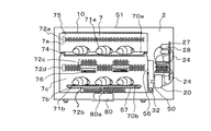
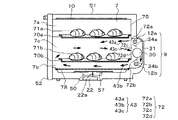
heating
hot air
fan
Prior art date
Legal status (The legal status is an assumption and is not a legal conclusion. Google has not performed a legal analysis and makes no representation as to the accuracy of the status listed.)
Withdrawn
Application number
JP2002188829A
Other languages
Japanese (ja)
Inventor
Mitsuru Honma
本間 満
Hideyuki Kimura
木村 秀行
Satoru Sannomaru
山王丸 悟
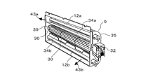
Minoru Endo
遠藤 実
Sei Ozawa
小沢 聖
Current Assignee (The listed assignees may be inaccurate. Google has not performed a legal analysis and makes no representation or warranty as to the accuracy of the list.)
Hitachi Global Life Solutions Inc
Original Assignee
Hitachi Hometec Ltd
Priority date (The priority date is an assumption and is not a legal conclusion. Google has not performed a legal analysis and makes no representation as to the accuracy of the date listed.)
Filing date
Publication date
Application filed by Hitachi Hometec Ltd filed Critical Hitachi Hometec Ltd
Priority to JP2002188829A priority Critical patent/JP2004028513A/en
Publication of JP2004028513A publication Critical patent/JP2004028513A/en
Withdrawn legal-status Critical Current

Links

Images

Landscapes

  • Electric Ovens (AREA)

Abstract

【課題】加熱調理に有効な熱風を加熱室に供給し、熱効率の良好なオーブン加熱による省エネ化と焼きムラの少ない調理が行える加熱調理器を提供する。
【解決手段】空気43を加熱する熱風ユニット9と、被加熱物71を収納する加熱室7の背面壁75に空気43が導通する通風口72を備えた加熱調理器において、熱風ユニット9から加熱室7に空気43を供給する二つ以上の通風口72と、加熱室7から熱風ユニット9に空気43を供給する通風口72とし、熱風ユニット9内に空気43の流れを制御する流れ誘導手段34を設け、通風口72から熱風ユニット9に流入した空気43を少なくとも二方向に分流し、熱風化した空気43を加熱室7の背面壁75に設けた二つ以上の通風口72から加熱室7に供給する。
【選択図】 図1
An object of the present invention is to provide a heating cooker that supplies hot air effective for heating cooking to a heating chamber, saves energy by heating the oven with good thermal efficiency, and performs cooking with less uneven grilling.
In a heating cooker provided with a hot air unit 9 for heating air 43 and a ventilation port 72 for conducting air 43 to a rear wall 75 of a heating chamber 7 for accommodating an object 71 to be heated, heating is performed from the hot air unit 9. A flow inducing means for controlling the flow of the air 43 into the hot air unit 9 by providing two or more vents 72 for supplying the air 43 to the chamber 7 and an air outlet 72 for supplying the air 43 from the heating chamber 7 to the hot air unit 9 34, the air 43 flowing into the hot air unit 9 from the ventilation port 72 is diverted in at least two directions, and the hot-airized air 43 is supplied from the two or more ventilation ports 72 provided on the back wall 75 of the heating chamber 7 to the heating chamber. 7
[Selection diagram] Fig. 1

Description

【0001】
【発明の属する技術分野】
本発明は、熱風によって被加熱物を調理する加熱調理器に関するものである。
【0002】
【従来の技術】
従来の加熱調理器は、特開平11−166738号公報に開示されているように、被加熱物の調理される加熱室の背面の後方にファン装置を備え、加熱室内の空気を加熱室下部の吸込口から熱風循環装置(熱風ユニット)のファンケーシング内に吸い込み、熱風用ヒータで加熱された熱風を中央部の吹き出し口から加熱室内に吹き出す構造であるとともに、加熱室の上面及び下面に設けられたヒータによって、加熱室内部に配置された上下二段の皿上の被加熱物を、3つのヒータの制御によって調理するものがあった。
【0003】
【発明が解決しようとする課題】
従来の加熱調理器では、加熱室内に上下二段に配置される調理皿を加熱するために下段調理皿の下方の底面に別途加熱ヒータを要すため、部品点数が増すとともに組立性が良好でない。
【0004】
また、加熱室上下に取り付ける加熱ヒータが加熱室壁の外面に配置されるため、外部への熱漏洩が大きく熱損失が生じ易い。また、その加熱ヒータは熱風より熱効率が悪く、加熱室内部に熱を伝え難いため、省エネ性が良好でないという課題があった。
【0005】
本願発明は、上記の課題のうち少なくとも1つを解決するために為されたものである。
【0006】
【課題を解決するための手段】
本発明は上記の課題を解決するために、被加熱物を収納する加熱室と、該加熱室に配置される調理皿と、加熱室に空気を循環させる一つの貫流ファンと空気を加熱する熱風ヒータから構成される熱風ユニットと、該熱風ユニットと加熱室間で空気が導通する通風口を備えた加熱調理器であって、通風口が熱風ユニットから加熱室に空気を供給する二つ以上の通風口と、加熱室から熱風ユニットに空気を供給する通風口であり、熱風ユニット内に空気の流れを制御する流れ誘導手段を設け、通風口から熱風ユニットに流入した空気を少なくとも二方向に分流し、該空気を加熱室の二つ以上の通風口から加熱室に供給する構成にすることにより解決できる。
【0007】
或いは、流れ誘導手段によって二方向に分流した空気を加熱室に供給する通風口が、貫流ファンの上方位置と下方位置に設けた構成とする。
【0008】
ここで、熱風ユニット内の流れ誘導手段を貫流ファンに二方向から交互に近接させて配置する。
【0009】
或いは、流れ誘導手段が貫流ファンの後方に設けた流れ誘導手段と該貫流ファン上下位置に設けられた導風板で構成する。
【0010】
または、被加熱物を収納する加熱室と、該加熱室に配置される調理皿と、加熱室に空気を循環させる一つの貫流ファンと空気を加熱する熱風ヒータから構成される熱風ユニットと、加熱室の背壁面に設けられ、熱風ユニットから加熱室に空気を供給する二つ以上の通風口と、加熱室から熱風ユニットに空気を供給する通風口を備えた加熱調理器において、貫流ファンが調理皿間の位置に配置される上下方向の位置関係とするものである。
【0011】
【発明の実施の形態】
以下、本発明の一実施例を図面を用いて説明する。
【0012】
図1及び図2に本発明の第一の実施形態の側面断面及び正面断面図を示す。これらの図は、本発明の加熱調理器の一例として、オーブン調理機能をもったターンテーブル式オーブンレンジに適用したものである。
【0013】
図において、キャビネット51の内側には、被加熱物71を収納し、加熱調理を行う加熱室7が設けられ、加熱室7の前面には被加熱物71を出し入れできる開閉式のドア部52が回動可能に設けられている。
【0014】
また、加熱室7の底面下方にはアンテナモータ(図示せず)と重量センサ(図示せず)などから構成されるセンサユニット80が配置され、加熱室7の底面にセンサユニット80の回転軸80aが突出している。
【0015】
また、ドア部52の側面には、加熱調理を設定する操作パネル(図示せず)が設けられる。
【0016】
この操作パネルの後方となる加熱室7の右側には機械室2が配置されている。この機械室2には、被加熱物71をマイクロ波加熱するために必要な部品、例えばマグネトロン20や制御基板27、二つの冷却ファン24等が設けられている。制御基板27にはマグネトロン20やセンサユニット80などを制御するマイコン28が搭載されている。
【0017】
マグネトロン20は加熱室7側壁のマイクロ波照射面56と導波管50とで連結されており、マグネトロン20より放射されるマイクロ波がマイクロ波照射面56を介して加熱室7内部に供給される構造となっている。
【0018】
加熱室7内壁の左右両側面には、底面と概略並行に内側に突出した加熱室7の概略同じ幅の角型の調理皿70を保持する支持部74が上下二段に設けられており、調理皿70を上段の調理皿70a、下段の調理皿70bの二枚に配置可能な構成となっている。
【0019】
加熱室7の上側の略全面には平面状の上ヒータ10が設けられ、グリル加熱時にマイコン28でON/OFFおよび電力制御することにより被加熱物71の表面を加熱できる。
【0020】
ドア部52と向かい合う加熱室7の背面壁75の3箇所に通風口72が設けられている。それぞれの通風口72は多数のパンチング孔72pで形成され、加熱室7上面と上段の支持部74に配置した上調理皿70aの間に設けられた加熱室7に空気43aを供給する通風口72aと、上調理皿70aと下段支持部74に配置した下調理皿70bの間に設けられた加熱室7から空気43cを排出する通風口72c、72dと、下調理皿70bと加熱室7底面の間に設けられた加熱室7に空気43bを供給する通風口72bで構成されている。
【0021】
ここで、通風口72のパンチング孔72pの孔形状は、円形で無くともマグネトロン20の発振によって照射されるマイクロ波が加熱室7外部に漏洩しない大きさ、例えば3mmから6mm程度であれば、楕円でも多角形でもよい。
【0022】
また、通風口72a、72bは、概略加熱室7の左右幅方向一杯に配置されているが、通風口72c、72dは加熱室7の幅方向に千鳥状になるように上下位置に交互に5列並べた構成となっている。
【0023】
ここで、本実施形態では通風口72c、72dを千鳥状に上下位置に5列並べた構成であるが、例えば千鳥状の配置を7列、9列と増加すれば、より通風口70a、70bを通過して吹き出る空気43a、43bの風速分布を容易に均一化することができるし、配列を3列と減らして熱風ユニット9内の流れの干渉を減らす構成としても良い。また、被加熱物71を少ない焼きムラで調理可能であれば通風口72c、72dの列数が奇数でなく偶数であっても良い。
【0024】
通風口72a、72bの断面積を狭く構成するほど、通風口72a、72bから吹き出される空気43a、43bの風速が増加し、高温化した空気43a、43bをより遠方のドア部52側に運ぶことができるので加熱室7内部の温度を均一化でき、被加熱物71を少ない焼きムラでオーブン調理できる。
【0025】
また、通風口72c、72dの幅は、熱風ユニット9内の流れ誘導手段34が貫流ファン30に近接している部分(図4で後述)と概略同じ幅で構成される。
【0026】
後述するが、以上のような構成にすると、一箇所の通風口72c、72dから熱風ユニット9に流入した空気を二方向に分流でき、通風口72a、72bから加熱室7に空気を供給することができる。
【0027】
また、加熱室7の背面壁75には加熱室7の外側(熱風ユニット9側)に突き出た突起76が設けられており、加熱室7の背面壁75と熱風ユニット9の貫流ファン30の間隙を狭めるような構成となっている(図4で後述)。
【0028】
後述するが、以上のような構成にすると、貫流ファン30による風量を増加できる。
【0029】
図3に熱風ユニット9の斜視断面図を示す。
【0030】
被加熱物71のオーブン加熱調理を行う熱風ユニット9は、通風口72が設けられた加熱室7の背面壁75と熱風ユニット9の背面壁35の間に設けられた加熱室7の幅方向に延びた貫流ファン30と、流れ誘導手段34a、34bと、貫流ファン30を回転させるファンモータ32と、貫流ファン30から吹き出された空気43cを加熱する熱風ヒータ12a、12bで構成されている。
【0031】
熱風ユニット9は、上調理皿70aと下調理皿70bの間に設けられた通風口72cの概略加熱室7の背面壁75の外側に貫流ファン30が配置されており、その貫流ファン30は熱風ユニット9の側壁に設けられた耐熱・摺動・防振部材からなる保持部39とファンモータ32で保持されており、ファンモータ32の回転とともに貫流ファン30が滑らかに回転することができる。
【0032】
熱風ユニット9内の貫流ファン30の概略上下位置には、流れ誘導手段34a、34bが設置されている。
【0033】
また、熱風ユニット9から吹き出される空気43a、43bを加熱室7に供給する通風口72a、72bの上流側に位置する熱風ユニット9内には、循環空気43を加熱する二つの熱風ヒータ12a、12bがそれぞれ設けられる。
【0034】
ここで熱風ヒータ12は例えば棒状の石英管およびシーズヒータ等で構成され、平滑面でも良いがその表面に多数の放熱フィン(図示せず)を設けたものであっても良い。また、熱風ヒータ12は、熱風ユニット9内部に配置可能であれば、例えばU字状であっても、面状であっても良いし、該熱風ヒータ12をループ状にして熱風ヒータ12a、12bを1本で構成してもよい。
【0035】
ファンモータ32は熱風ユニット9側面壁の外方に設けられ、機械室2内部に搭載された冷却ファン24の冷却空気流で冷却される。
【0036】
ここで、ファンモータ32の冷却が冷却ファン24のみで不十分であれば、ファンモータ32の回転軸32a上に例えば遠心ファン(図示せず)などを設けてもよいし、個別ファン(図示せず)などによって冷却空気を供給してもよい。
【0037】
また、熱風ユニット9の背面壁35には、熱風ユニット9内側に突出た突起36が設けられている。突起36は流れ誘導手段34aの貫流ファン30に近接し、通風口72dの加熱室7の幅方向の長さと概略同程度の長さで設けられる。
【0038】
突起36により、貫流ファン30のブレード100と熱風ユニット9の背面壁35の間隙を制御できるので、ブレード100によって効率の良い貫流ファン30と背面壁35の間隙を広く構成し、高い貫流ファン30性能を得ることにより大風量化が実現できる。
【0039】
図4は加熱室7に設置される熱風ユニット9の側面断面図であり、図4(a)に通風口72cを含む側面断面(図2に示すy’−y’断面)を、図4(b)に通風口72dを含む側面断面(図2に示すy−y断面)をそれぞれ示す。
【0040】
図4(a)では加熱室7の背面壁75に設けられた通風口72cを介して、加熱室7から熱風ユニット9に空気43cが流れ込み、貫流ファン30の下方に近接して設置された流れ誘導手段34bによって、熱風ユニット9内で空気43cが貫流ファン30から下方向に向かって吹き出され、熱風ヒータ12bで加熱された空気43bが加熱室7内部に供給される。
【0041】
また、加熱室7の背面壁75には加熱室7の外側(熱風ユニット9側)に向けた突起76を設けた構成となっており、貫流ファン30のケーシングの一部として、貫流ファン30と背面壁75の間隙、例えば1〜5mmに調整して設置される。
【0042】
例えば、貫流ファン30が図示した方向38に回転する場合、効率よく空気43cを送風するために貫流ファン30のブレード(図3の100)と概略ブレード外周に沿ったケーシングが必要であり、熱風ユニット9の背面壁35及びその突起76がケーシングの役目を兼ねた構成となっている。
【0043】
ここで、貫流ファン30のケーシングを構成する加熱室7の背面壁75の突起76は、貫流ファン30の風量を増大させるために、より貫流ファン30の円弧に沿って近接して成形するのが望ましいが、突起76等が無くとも風量が十分であれば成形しなくても良い。
【0044】
一方、図4(b)では加熱室7の背面壁75に設けられた通風口72dを介して、加熱室7から熱風ユニット9に空気43cが流れ込み、貫流ファン30の上方に近接して設置された流れ誘導手段34aによって、熱風ユニット9内で空気43cが貫流ファン30から上方向に向かって吹き出され、熱風ヒータ12aで加熱された空気43aが加熱室7内部に供給される。
【0045】
また、熱風ユニット9の背面壁35には、熱風ユニット9の内側に向けた突起36を設けた構成となっており、貫流ファン30のケーシングの一部として、貫流ファン30と熱風ユニット9の背面壁35の間隙を、例えば1〜5mmに調整して設置されている。
【0046】
図4(b)では熱風ユニット9の背面壁35及びその突起36がケーシングを兼ねた構造となっており、効率よく空気43cを貫流ファン30下方向に吹き出す構成となっている。
【0047】
つまり、本実施形態では貫流ファン30のケーシング部分が、図4(a)に示す加熱室7の背面壁75及びその突起76と、図4(b)に示す熱風ユニット9の背面壁35及びその突起36が交互に形成された構成となっている。
【0048】
貫流ファン30より交互に吹き出された空気43は通風口72a、72bまでに加熱室7幅方向に均一化されて吹き出され、熱風ヒータ12a、12bで加熱され熱風化した空気43a、43bはそれぞれ通風口72a、72bから加熱室7に供給される。
【0049】
以上の構成より、オーブン加熱調理時の動作について、図1から図4を用いて、概略加熱室7の幅の角型の調理皿70が上下段に二枚配置した場合を説明する。
【0050】
例えば、パン等の被加熱物71が載せられた調理皿70は、前方のドア部52を開け、加熱室7の左右壁面に設けられた支持部74をスライドさせながら加熱室7の背面壁75に調理皿70が接触するまで内部に押し込まれる。
【0051】
調理皿70が上下段に二枚配置された後、ドア部52を閉めオーブン調理が開始される。
【0052】
オーブン調理の開始は、被加熱物71の加熱時間や加熱温度などの設定が終了した後、機械室2の前方の操作パネル(図示せず)上のボタンで行われる。調理が開始されると、熱風ユニット9内のファンモータ32の回転駆動により貫流ファン30が回転を始める。
【0053】
また、ファンモータ32の駆動と同時に、貫流ファン30の回転によって吐出された空気は、熱風ユニット9内部に配置された熱風ヒータ12a、12bの発熱により温度上昇し、加熱室7に熱風となった空気43a、43bを供給する。
【0054】
ここで、加熱室7に供給される空気43a、43bは熱風ユニット9から加熱室7への風路となる通風口72a、72bで風路断面積が縮小されることにより、加熱室7の幅方向に少ない風速分布で概略加熱室7幅一杯に帯状の空気43a、43bとなって供給される。
【0055】
通風口72aから出た空気43aは、加熱室7上面と上調理皿70aに挟まれた加熱室7の内部空間7aを加熱室7の背面方向からドア部52方向に向かって流れ、この間に上調理皿70aの被加熱物71aを加熱するとともに加熱室7の上面部を加熱しながら、加熱室7の内部温度を上昇させる。
【0056】
加熱室7上面と上調理皿70aの間を流れた熱風43aは、ドア部52と上調理皿70aの間隙を通って下方向に流れ、上調理皿70aと下調理皿70bの内部空間7cを通ってドア部52側から加熱室7の背面壁75側に向かって流れる。
【0057】
一方、通風口72bから出た空気43bは、下調理皿70bと加熱室7底面に挟まれた加熱室7の内部空間7bを加熱室7の背面壁75方向からドア部52方向に向かって流れ、この間に下調理皿70bの底面を加熱するとともに加熱室7の底面部を加熱しながら、加熱室7の内部温度を上昇させる。
【0058】
下調理皿70bと加熱室7底面の間を流れた空気43bは、ドア部52と下調理皿70bの間隙を通って上方向に流れ、上調理皿70aと下調理皿70bの内部空間7cを通ってドア部52側から加熱室7の背面壁75側に向かって流れる。
【0059】
つまり、通風口72a、72bから出た空気43a、43bは上調理皿70aと下調理皿70bの内部空間7cで混合した空気43cとなって、ドア部52側から加熱室7背面側に向かって流れ、この間に上調理皿70aの底面を加熱するとともに下調理皿70b上の被加熱物71bを加熱する。
【0060】
加熱室7の背面壁75には上調理皿70aと下調理皿70bの間隙を通過する被加熱物71などに熱を奪われた空気43cが熱風ユニット9に流れ込むように上調理皿70aと下調理皿70bの内部空間7cに通風口72c、72dが配置されている。
【0061】
通風口72cを通って加熱室7から出た空気43cは、熱風ユニット9内の貫流ファン30及び流れ誘導手段34bを介して貫流ファン30の下方向に送り出され、再び熱風ヒータ12bで加熱され、通風口72bから熱風の空気43bとなって加熱室7に吹き出される。
【0062】
一方、通風口72dを通って加熱室7から出た空気43cは、熱風ユニット9内の貫流ファン30及び流れ誘導手段34aを介して貫流ファン30の上方に送り出され、再び熱風ヒータ12aで加熱され、通風口72bから熱風の空気43aとなって加熱室7に吹き出される。
【0063】
このように貫流ファン30により加熱室7の上下位置の通風口72a、72bから加熱室7内に供給した空気43a、43bは、被加熱物71などにより熱を奪われた後に、中央の通風口72c、72dから熱風ユニット9に戻り循環する流れ構成となる。
【0064】
また、一つの貫流ファン30で上調理皿70aの上方と、下調理皿70b下方の両側から上調理皿70aと下調理皿70bの上下間に流れる空気43を供給できるので、例えば加熱室7の上面または底面に別途設けられたヒータなどを使わず、空気43のみで上調理皿70aと下調理皿70bの被加熱物71をムラ無く加熱でき、熱損失の少ない省エネ性の高い加熱ができる。
【0065】
加熱室7内部の温度は、例えば加熱室7側面に設けた熱電対やサーミスタ等の温度センサ(図示せず)で感知し、加熱室7の温度が設定値よりも高い場合、熱風ヒータ12への電力供給を止める、或いは低電力化し、貫流ファン30のみを回転駆動させる。
【0066】
つまり、加熱室7の温度は熱風ヒータ12のON/OFFおよび電力で制御される。ここで、温度センサ(図示せず)は非接触式である赤外線温度センサであれば、加熱室7任意の壁面温度や被加熱物71温度を直に計測することも可能である。
【0067】
被加熱物71のオーブン調理では加熱室7壁面が高温となり、機械室2側への熱漏洩による機械室2の温度上昇を抑制するために機械室2内部の冷却ファン24が駆動される。
【0068】
冷却ファン24の駆動は調理開始とともに常時或いは間欠的に行っても、例えばファンモータ32等の温度を検知して行ってもよい。
【0069】
本実施形態では機械室2を加熱室7の側面に設けた構造について説明したが、機械室2及び操作パネル(図示せず)が、加熱室7の底面或いは上面に配置した構造についても同様の構成及び効果が実現できる。
【0070】
図5に熱風ユニット9の他の実施形態の側面断面図を示す。
【0071】
図5は図4と同様に加熱室7の背面に設置される熱風ユニット9であり、図5(a)に通風口72cを含む側面断面を、図5(b)に通風口72dを含む側面断面をそれぞれ示す。
【0072】
図5(a)では加熱室7の背面壁75に設けられた通風口72cを介して、加熱室7から熱風ユニット9に空気43cが流れ込み、貫流ファン30の下方に近接して設置された流れ誘導手段34bによって、熱風ユニット9内で空気43cが貫流ファン30から下方向に向かって吹き出される。
【0073】
本実施形態では貫流ファン30の外周に導風板37aが設けられ、貫流ファン30の上方へ漏洩する空気43cの流れを遮断する構成となっており、より高いファン性能が得られ、熱風ヒータ12bで加熱された大風量の空気43bを加熱室7に供給できる。
【0074】
一方、図5(b)でも加熱室7の背面壁75に設けられた通風口72dを介して、加熱室7から熱風ユニット9に空気43cが流れ込み、貫流ファン30の上方に近接して設置された流れ誘導手段34aによって、熱風ユニット9内で空気43cが貫流ファン30から上方向に向かって吹き出される。
【0075】
貫流ファン30の外周には導風板37bが設けられ、貫流ファン30の下方へ漏洩する空気43cの流れを遮断する構成となっており、熱風ヒータ12aで加熱された大風量の空気43aを効率よく加熱室7に供給できる。
【0076】
つまり、本実施形態では熱風ユニット9内部に貫流ファン30の導風板37a、37bが加熱室7の幅方向に上下反対向きに交互に形成される構成となる。
【0077】
貫流ファン30より交互に吹き出された空気43は、図4と同様に通風口72a、72bまでに加熱室7幅方向に均一化されて吹き出され、熱風ヒータ12a、12bで加熱された熱風化した空気43a、43bとなって加熱室7に供給される。
【0078】
図6及び図7に加熱調理器の他の実施形態の側面断面及び正面断面図を示す。
【0079】
本実施形態は加熱室7内部に角型の上調理皿70aと回転可能な丸型の下調理皿70bを上下段に二枚配置させてオーブン加熱を行うターンテーブル式の加熱調理器である。
【0080】
図において、キャビネット51の内側には、被加熱物71を収納し、加熱調理を行う加熱室7が設けられ、加熱室7前面には被加熱物71を出し入れできる開閉式のドア部52が回動可能に設けられている。
【0081】
また、加熱室7の底面下方にはアンテナモータ(図示せず)と重量センサ(図示せず)などから構成されるセンサユニット80が配置され、加熱室7の底面に配置される円形のアンテナ網57がセンサユニット80の回転軸80a上に連結されている。
【0082】
また、ドア部52の側面には加熱調理を設定する操作パネル(図示せず)が設けられ、操作パネルの後方となる加熱室7の右側には機械室2が配置されている。
【0083】
機械室2の構成は図2の加熱調理器と同様であり、説明を省略する。
【0084】
加熱室7内壁の左右両側面には底面と概略並行に内側に突出した加熱室7の概略幅の角型の上調理皿70aを保持する支持部74が設けられており、上調理皿70aとアンテナ網57上に配置される丸型の下調理皿70bを加熱室7に二枚配置して調理できる構成となっている。
【0085】
ドア部52と向かい合う加熱室7の背面壁75の通風口72の後方に設けられた熱風ユニット9は図3と同様な構成であり、説明を省略する。
【0086】
また、熱風ユニット9に加熱室7から空気43cを供給する通風口72c、72d及び加熱室7上面と上調理皿70aの間の内部空間7aに空気43aを供給する通風口72aも図2と同様な構成であり説明を省略する。
【0087】
本実施形態では、下調理皿70bと加熱室7底面の内部空間7bに空気43bを供給する通風口72bを加熱室7の幅に対して中央付近のみに配置した構成となっており、通風口72bから吹き出た空気43bが加熱室7背面下隅から丸型の下調理皿70b上方へ漏洩し難い構造となっている。
【0088】
ここで、通風口72bから吹き出す空気43bが高風速で下調理皿70b底面を十分加熱できるならば、図2に示すように加熱室7幅一杯にパンチング孔を構成しても良い。
【0089】
本実施例に沿って加熱室7に加熱室7幅の角型の上調理皿70aと回転アンテナ57上の円形状の下調理皿70bが上下段に二枚配置した構成のオーブン動作について説明する。
【0090】
例えばパン等の被加熱物71aが載せられた上調理皿70aは、前方のドア部52より、加熱室7の左右に配置された支持部74をスライドさせながら加熱室7の背面壁75に調理皿70aが接触するまで内部に押し込まれる。
【0091】
また、被加熱物71bが載せられた下調理皿70bは、回転アンテナ57に載せられ、調理皿70が上下段に二枚配置された後、ドア部52を閉めオーブン調理が開始される。
【0092】
オーブン調理の開始は被加熱物71の加熱時間や加熱温度などの設定が終了した後、機械室2の前方の操作パネル(図示せず)上のボタンで行われる。
【0093】
調理が開始されると熱風ユニット9内のファンモータ32の回転駆動により貫流ファン30が回転を始めるとともに、加熱室7内部の回転アンテナ57の回転によって下調理皿70bも回転を始める。
【0094】
また、ファンモータ32の駆動と同時に貫流ファン30の回転によって吐出された空気43cは、熱風ユニット9内部に配置された熱風ヒータ12a、12bの発熱により温度上昇し、加熱室7に熱風化した空気43a、43bを供給する。
【0095】
ここで、加熱室7に供給される空気43aは熱風ユニット9と加熱室7の風路となる通風口72aで風路面積が縮小されることにより、加熱室7幅方向に少ない風速分布で概略加熱室7幅一杯の帯状の熱風となって供給される。
【0096】
通風口72aから出た熱風43aは加熱室7上面と上調理皿70aに挟まれた加熱室7の内部空間7aを加熱室7の背面方向からドア部52方向に向かって流れ、この間に上調理皿70aの被加熱物71aを加熱するとともに加熱室7上面部を加熱しながら、加熱室7の内部温度を上昇させる。
【0097】
加熱室7上面と上調理皿70aの間を流れた熱風43aはドア部52と上調理皿70aの間隙を通って下方向に流れ、上調理皿70aと下調理皿70bの間を通ってドア部52側から加熱室7の背面壁75側に向かって流れる。
【0098】
一方、加熱室7に供給される空気43bは熱風ユニット9と加熱室7の風路となる通風口72bで風路面積が縮小されることにより加速され、加熱室7の背面壁75下部中央の通風口72bより下調理皿70b下方に向けて供給される。
【0099】
通風口72bから出た空気43bは下調理皿70bと加熱室7底面に挟まれた加熱室7の内部空間7bを加熱室7の背面壁75方向からドア部52方向に向かって流れ、この間に下調理皿70bの底面を加熱するとともに加熱室7底面部の加熱しながら、加熱室7の内部温度を上昇させる。
【0100】
下調理皿70bと加熱室7底面の内部空間7bを流れた空気43bはドア部52と下調理皿70bの間隙を通って上方向に流れ、上調理皿70aと下調理皿70bの間を通ってドア部52側から加熱室7の背面壁75側に向かって流れる。
【0101】
ここで、回転アンテナ57上に配置された下調理皿70bは加熱調理中に回転しており、通風口72bから吹き出された空気43bで被加熱物71bをムラ無く調理できる。
【0102】
よって、第一の実施形態と同様に、通風口72a、72bから出た空気43a、43bは、上調理皿70aと下調理皿70bの内部空間7cで混合した空気43cとなって、ドア部52側から加熱室7背面壁75側に向かって流れ、この間に上調理皿70aの底面を加熱するとともに下調理皿70bの被加熱物71bを加熱する。
【0103】
また、被加熱物71などに熱を奪われた空気43cは上調理皿70aと下調理皿70bの内部空間7cに設けられた通風口72c、72dより熱風ユニット9に流れ込み、熱風ユニット9内の貫流ファン30を介して再び熱風ヒータ12で加熱されて熱風化し、通風口72a、72bから加熱室7に吹き出される循環流れとなる。
【0104】
本実施形態においても、一つの貫流ファン30で構成させる熱風ユニット9内に設けた流れ誘導手段34a、34bによって、上調理皿70aの上方と下調理皿70b下方の両側から上調理皿70aと下調理皿70bの上下間に流れる空気43を供給できるので、加熱室7の上面または底面に別途設けられたヒータなどを使わず、熱風化した空気43のみで上調理皿70aと下調理皿70bの被加熱物71をムラ無く加熱でき、熱損失の少ない省エネ性の高い加熱ができる。
【0105】
このように、加熱室7に配置される調理皿70の形態によらず、熱効率の良好な加熱調理ができる。
【0106】
また、加熱室7に回転アンテナ57が配置されないターンテーブルレス式の加熱調理器でも図1から7に示す熱風ユニット9が設置でき、同様な効果があることは言うまでもない。
【0107】
図8及び図9に加熱調理器の他の実施形態の側面断面図及び正面断面図を示す。
【0108】
本実施形態は加熱室7の底部をマイクロ波透過性の高い例えばガラス板78で構成したターンテーブルレスオーブンレンジに本発明の熱風ユニット9を配置させたものである。
【0109】
図において、キャビネット51の内側には、被加熱物71を収納し、加熱調理を行う加熱室7が設けられ、加熱室7前面には被加熱物71を出し入れできる開閉式のドア部52が回動可能に設けられている。
【0110】
また、ドア部52の側面には、加熱調理を設定する操作パネル(図示せず)が設けられる。
【0111】
この操作パネルの後方となる加熱室7の右側に配置された機械室2の構成は図2と同様であり、説明を省略する。
【0112】
機械室2内のマグネトロン20は、加熱室7内のガラス板78と導波管50で連結されており、マグネトロン20より放射されるマイクロ波がガラス板78を透過して加熱室7内部に供給する構造となっている。
【0113】
ガラス板78下方にはマイクロ波を拡散させる金属部材、例えば円形のアンテナ網57が配置され、その中心部が導波管50下方に配置されたアンテナモータ22の軸22a上に連結されている。
【0114】
また、加熱室7内壁の左右両側面には底面と概略並行に内側に突出した加熱室7の概略同じ幅の調理皿70a、70bを保持する支持部74が設けられており、調理皿70a、70bを加熱室7内に上下段として二枚配置可能な構成となっている。
【0115】
加熱室7の上側の略全面には平面状の上ヒータ10が設けられ、オーブン加熱時にマイコン28の支持でON/OFFおよび電力制御することにより被加熱物71を加熱する。
【0116】
ドア部52と向かい合う加熱室7の背面壁75には通風口72が設けられている。この通風口72は多数のパンチング孔72pで形成され、上調理皿70aの底面近傍に設けられた通風口72aと、該通風口72aと下調理皿70bの間に設けられた通風口72c、72dと、下調理皿70bと加熱室7底面の間に設けられた通風口72bで構成されている。
【0117】
上調理皿70aの底面近傍に設けられた通風口72a、及び加熱室7底面と下調理皿70bの間に設けられた通風口72bは、概略加熱室7の左右幅方向に配置されている。
【0118】
また、通風口72c、72dは図2と同様に加熱室7の幅方向に千鳥状に並べた構成となっている。
【0119】
図10に熱風ユニット9の斜視断面図を示す。
【0120】
加熱室7の背面に配置される熱風ユニット9は、図3と同様に通風口72が設けられた加熱室7の背面壁75と熱風ユニット9の背面壁35の間に設けられた加熱室7の幅方向に延びた貫流ファン30と、熱風ユニット9内部に設けられた流れ誘導手段34a、34bと、貫流ファン30を回転させるファンモータ32と、貫流ファン30から吹き出された空気43a、43bを加熱する熱風ヒータ12a、12bで構成されている。
【0121】
図示した熱風ユニット9は図3に示した熱風ユニット9と同様な構成であり、説明を省略する。
【0122】
熱風ユニット9内の貫流ファン30の概略上下位置には、図4と同様に流れ誘導手段34a、34bが設置されるとともに、熱風ユニット9から吹き出される空気43a、43bを加熱室7に供給する通風口72a、72bの上流側に熱風ヒータ12a、12bが設けられている。
【0123】
本実施形態では、空気43aが吹き出される通風口72aと加熱室7から熱風ユニット9に空気43cを送る通風口72c、72dが、調理皿70aと調理皿70bの内部空間7cの加熱室7の背面壁75に設けられた構成となっている。
【0124】
よって、通風口72aから吹き出た空気43aは上調理皿70a底面に沿ってドア部52方向に流れた後、例えば加熱室7中央付近で空気43cと混合してドア部52側から熱風ユニット9側に向かって流れるとともに、加熱室7の背面壁75側へ流れる空気43cの空気温度を上昇させることができる。
【0125】
従って、通風口72bから吹き出た空気43bが、下調理皿70bの底面と加熱室7底面の間を通って上調理皿70aと下調理皿70bの間に入り、通風口72cに入るまでに、被加熱物71等に奪われた熱によって下がった空気43cの温度を、通風口72aから吹き出た空気43aによって補うことができるので、下調理皿70b上の被加熱物71bを加熱室7の奥行き配置位置によらず、少ない焼きムラで調理できる。
【0126】
次に本実施形態におけるオーブン動作について説明する。
【0127】
例えばパン等の被加熱物71が載せられた調理皿70a、70bは、前方のドア部52より、加熱室7の左右に配置された支持部74をスライドさせながら加熱室7背面に調理皿70a、70bが接触するまで内部に押し込まれ、調理皿70a、70bが上下段に二枚配置された後、ドア部52を閉めオーブン調理が開始される。
【0128】
オーブン調理の開始は被加熱物71の加熱時間や加熱温度などの設定が終了した後、機械室2の前方の操作パネル(図示せず)上のボタンで行われる。
【0129】
調理が開始されると熱風ユニット9内のファンモータ32の回転駆動により貫流ファン30が回転を始める。
【0130】
本実施形態では上調理皿70a上の被加熱物71aの上面を上ヒータ10の熱放射で下面を熱風化した空気43aで加熱し、下調理皿70b上の被加熱物71bの上面を空気43cで、下面を空気43bで加熱する構成となっている。
【0131】
従って、上ヒータ10と熱風ヒータ12の給電方法は、互いに給電時間をON/OFFするか、或いは低電力で同時給電するかのいずれかで行うことになる。
【0132】
例えば、給電時間の設定は加熱室7や調理皿70a、70bの熱容量、被加熱物71の種類や量等によって決められる。
【0133】
ファンモータ32の駆動と同時に、貫流ファン30の回転によって吐出された空気43は熱風ユニット9内部に配置された熱風ヒータ12a、12bの発熱により温度上昇し、加熱室7に熱風化した空気43a、43bを供給する。
【0134】
ここで、加熱室7に供給される空気43aは、熱風ユニット9と加熱室7の風路となる通風口72aで風路断面積が縮小されることにより、加熱室7幅方向に少ない風速分布で概略加熱室7幅の帯状の空気43aとなって供給される。
【0135】
通風口72aから出た熱風43aは上調理皿70a近傍からドア部52方向に向かって流れ、この間に上調理皿70aの底面を加熱するとともに調理皿70間を流れる空気43cの空気温度を上昇させる。
【0136】
通風口72aから出た空気43aは、例えば加熱室7の中央付近で折り返し、ドア部52側から加熱室7の背面壁75方向に向かう空気43cとなって、熱風ユニット9に流れ込む。
【0137】
一方、通風口72bから出た空気43bは下調理皿70bと加熱室7底面に挟まれた加熱室7の内部空間7bを加熱室7の背面方向からドア部52方向に向かって流れ、この間に下調理皿70bの底面を加熱するとともに加熱室7底面部の加熱しながら、加熱室7の内部温度を上昇させる。
【0138】
下調理皿70bと加熱室7底面の内部空間7bを流れた空気43bはドア部52と下調理皿70bの間隙を通って上方向に流れ、上調理皿70aと下調理皿70bの内部空間7cを通ってドア部52側から加熱室7の背面壁75側に向かって流れる。
【0139】
ここで、下調理皿70bの底面を介して流れた空気43cは、下調理皿70bや加熱室7底面と熱交換して温度が低下するが、通風口72aより吹き出された空気43aと混合し、再び温度上昇して調理皿70の内部空間7cを熱風ユニット9に向かって流れる。
【0140】
よって、通風口72a、72bから出た空気43a、43bは、上調理皿70aと下調理皿70bの間で混合した空気43cとなって、ドア部52側から加熱室7の背面壁75側に向かって流れるため、下調理皿70b上の被加熱物71bの奥行き方向の配置に対して、再温度上昇によって少ない焼きムラで調理することができる。
【0141】
また、被加熱物71bなどと熱交換した空気43cは加熱室7の背面壁75に設けられた通風口72c、72dより熱風ユニット9に流れ込み、熱風ユニット9内の貫流ファン30を介して再び熱風ヒータ12a、12bで加熱されて熱風化し、通風口72a、72bから空気43a、43bとなって加熱室7に吹き出される循環流れとなる。
【0142】
上調理皿70a下方の加熱室7の内部空間7b、7cのみでこのような空気43による被加熱物71の加熱が行われているが、上調理皿70a上の被加熱物71aは上ヒータ10の熱放射により加熱されるので、加熱室7に上下段に二枚配置した調理皿70a、70bを一度に少ない焼きムラで調理できる。
【0143】
本実施形態においても、一つの貫流ファン30で構成させる熱風ユニット9内に設けた流れ誘導手段34a、34bによって、下調理皿70b下方の加熱室7の内部空間7bに熱風化した空気43を供給できるので、加熱室7の底面に別途設けられたヒータなどを使わず、上調理皿70aと下調理皿70bの被加熱物71をムラ無く加熱でき、熱損失の少ない省エネ性の高い加熱ができる。
【0144】
ここで、本実施形態ではターンテーブルレス式のオーブンレンジを示したが、上下段二枚を同時にオーブン調理できる、例えば図1から図7のターンテーブル式オーブンレンジの加熱室7であっても同様なオーブン構成ができ、熱効率の良好な加熱調理ができることは言うまでもない。
【0145】
図11に加熱調理器の他の実施形態の側面断面図を示す。
【0146】
図において、キャビネット51の内側には、被加熱物71を収納し、加熱調理を行う加熱室7が設けられ、加熱室7の底面下方にセンサユニット80が配置される図1と同様な構成となっており、機械室(図示せず)の内部構成の説明は省略する。
【0147】
また、図1と同様に加熱室7の内壁には加熱室7の幅サイズの調理皿70を保持する支持部(図示せず)が上下二段に設けられており、角型の調理皿70を上下段に二枚配置できる。
【0148】
ドア部52と向かい合う加熱室7の背面壁75には、加熱室7上面と上調理皿70aの内部空間7aに設けられた通風口72aと、上調理皿70aと下調理皿70bの内部空間7cに設けられた通風口72cと、下調理皿70bと加熱室7底面の内部空間7bに設けられた通風口72bで構成されており、それぞれ概略加熱室7の左右幅方向に配置されている。
【0149】
加熱室7の背面壁75後方に設置される熱風ユニット9は、通風口72が設けられた加熱室7の背面壁75と、熱風ユニット9の背面壁35の間に設けられた加熱室7の幅方向に延びた貫流ファン30と、熱風ユニット9内部に貫流ファン30の上下に設けられた導風板37と、貫流ファン30から吹き出る空気43を分流して上下に流す熱風ユニット9の背面壁35に設けられた流れ誘導手段40と、貫流ファン30を回転させるファンモータ(図示せず)と、貫流ファン30から吹き出された空気43を加熱する熱風ヒータ12で構成される。
【0150】
通風口72cを介して加熱室7から熱風ユニット9に入る空気43cは、概略通風口72cと同じ高さ位置、且つ上調理皿70aと下調理皿70bの間位置に配置された貫流ファン30に吸い込まれ、貫流ファン30から熱風ユニット9の背面壁35側に設けられた流れ誘導手段40に向かって吹き出される。
【0151】
流れ誘導手段40で上下に分流された空気43は、熱風ヒータ12aを介して通風口72aから加熱室7に熱風化した空気43aを供給する流れと、熱風ヒータ12bを介して通風口72bから加熱室7に熱風化した空気43bを供給する流れとなる。
【0152】
通風口72aから吹き出た空気43aは加熱室7上面と上調理皿70aの内部空間7aをドア部52に向かって流れ、上調理皿70aとドア部52の間隙を下方向に向かって流れる。
【0153】
一方、通風口72bから吹き出た空気43bは下調理皿70bと加熱室7底面の内部空間7bを通ってドア部52に向かって流れ、下調理皿70bとドア部52の間隙を上方向に向かって流れる。
【0154】
よって、通風口72aから出た空気43aと、通風口72bから出た空気43bは混合した空気43cとなって、ドア部52側から熱風ユニット9側に向かって上調理皿70aと下調理皿70bの内部空間7cを流れる循環流れを構成する。
【0155】
従って、図1と同様に加熱室7に熱風化した空気43を供給して、同様なオーブン動作で被加熱物71を加熱調理できる。
【0156】
以上、図1から図11の本実施形態では機械室(図示せず)を加熱室7の側面に設けた構造について説明したが、機械室及び操作パネル(図示せず)が加熱室7の底面或いは上面に配置した構造であっても同様の構成及び効果が実現できる。
【0157】
また、本発明のいずれの実施例もターンテーブル式及びターンテーブルレス式オーブンレンジを問わず適用できるし、調理皿70が角皿及び丸皿いずれであっても、さらには該調理皿70が一段のみで調理される場合においても、同様の構成及び効果が実現できる。
【0158】
【発明の効果】
本発明によれば、請求項1から請求項5のように構成したので、加熱調理に有効な熱風を加熱室に供給し、熱効率の良好なオーブン加熱によって加熱室に配置された調理皿上の被加熱物を少ない焼きムラで調理ができるとともに高い省エネ性を実現できる。
【図面の簡単な説明】
【図1】本発明の第一の実施形態の加熱調理器の側面断面図である。
【図2】本発明の第一の実施形態の加熱調理器の正面断面図である。
【図3】本発明の第一の実施形態の加熱調理器の熱風ユニットの斜視図である。
【図4】本発明の第一の実施形態の加熱調理器の熱風ユニットの側面断面図である。
【図5】本発明の第二の実施形態の加熱調理器の熱風ユニットの側面断面図である。
【図6】本発明の第二の実施形態の加熱調理器の熱風ユニットの側面断面図である。
【図7】本発明の第三の実施形態の加熱調理器の正面断面図である。
【図8】本発明の第四の実施形態の加熱調理器の側面断面図である。
【図9】本発明の第四の実施形態の加熱調理器の正面断面図である。
【図10】本発明の第四の実施形態の加熱調理器の熱風ユニットの斜視図である。
【図11】本発明の第五の実施形態の加熱調理器の側面断面図である。
【符号の説明】
7・・・加熱室
9・・・熱風ユニット
12・・・熱風ヒータ
30・・・貫流ファン
32・・・ファンモータ
34・・・流れ誘導手段
37・・・導風板
40・・・流れ誘導手段
43・・・空気
70・・・調理皿
71・・・被加熱物
72・・・通風口
75・・・背面壁
[0001]
TECHNICAL FIELD OF THE INVENTION
The present invention relates to a cooking device for cooking an object to be heated by hot air.
[0002]
[Prior art]
As disclosed in Japanese Patent Application Laid-Open No. H11-166738, a conventional heating cooker is provided with a fan device at the rear of the back of a heating chamber in which an object to be heated is cooked, and air in the heating chamber is blown at a lower portion of the heating chamber. It has a structure in which the air is sucked into the fan casing of the hot air circulation device (hot air unit) from the suction port, and the hot air heated by the hot air heater is blown out from the outlet in the center into the heating chamber. Some heaters cook objects to be heated on upper and lower two-stage dishes placed inside a heating chamber by controlling three heaters.
[0003]
[Problems to be solved by the invention]
In the conventional heating cooker, a separate heater is required on the bottom surface below the lower cooking dish to heat the cooking dishes arranged in the upper and lower tiers in the heating chamber, so that the number of parts increases and the assemblability is not good. .
[0004]
Further, since the heaters installed above and below the heating chamber are arranged on the outer surface of the wall of the heating chamber, heat leakage to the outside is large and heat loss easily occurs. In addition, there is a problem that the heat efficiency of the heater is lower than that of the hot air, and it is difficult to transfer heat to the inside of the heating chamber.
[0005]
The present invention has been made to solve at least one of the above problems.
[0006]
[Means for Solving the Problems]
In order to solve the above-described problems, the present invention provides a heating chamber for accommodating an object to be heated, a cooking dish disposed in the heating chamber, one through-flow fan for circulating air to the heating chamber, and hot air for heating the air. A hot-air unit comprising a heater, and a heating cooker having a ventilation port through which air is conducted between the hot-air unit and the heating chamber, wherein the ventilation port supplies air from the hot-air unit to the heating chamber. A ventilation port for supplying air from the heating chamber to the hot air unit, and a flow guiding means for controlling the flow of air in the hot air unit; providing air flowing into the hot air unit from the ventilation port in at least two directions; The problem can be solved by flowing the air and supplying the air to the heating chamber from two or more ventilation ports of the heating chamber.
[0007]
Alternatively, the ventilation holes for supplying the air divided in two directions by the flow guiding means to the heating chamber are provided at an upper position and a lower position of the flow-through fan.
[0008]
Here, the flow guiding means in the hot air unit is arranged so as to be alternately close to the once-through fan from two directions.
[0009]
Alternatively, the flow guiding means is constituted by a flow guiding means provided behind the once-through fan and a baffle plate provided at a vertical position of the once-through fan.
[0010]
Alternatively, a heating chamber configured to include a heating chamber for storing an object to be heated, a cooking dish disposed in the heating chamber, a single flow fan for circulating air to the heating chamber, and a hot air heater for heating air; In a heating cooker provided on the back wall of the room and provided with two or more ventilation holes for supplying air from the hot air unit to the heating chamber and a ventilation hole for supplying air from the heating room to the hot air unit, the once-through fan cooks. This is a vertical positional relationship between the plates.
[0011]
BEST MODE FOR CARRYING OUT THE INVENTION
Hereinafter, an embodiment of the present invention will be described with reference to the drawings.
[0012]
1 and 2 show a side sectional view and a front sectional view of a first embodiment of the present invention. These figures are applied to a turntable type microwave oven having an oven cooking function as an example of the heating cooker of the present invention.
[0013]
In the figure, a heating chamber 7 for storing a heating target 71 and performing heating and cooking is provided inside a cabinet 51, and an opening / closing door portion 52 through which the heating target 71 can be taken in and out is provided at the front of the heating chamber 7. It is provided rotatably.
[0014]
A sensor unit 80 including an antenna motor (not shown) and a weight sensor (not shown) is disposed below the bottom of the heating chamber 7, and a rotation shaft 80 a of the sensor unit 80 is provided on the bottom of the heating chamber 7. Is protruding.
[0015]
An operation panel (not shown) for setting heating and cooking is provided on a side surface of the door section 52.
[0016]
The machine room 2 is disposed on the right side of the heating room 7 behind the operation panel. The machine room 2 is provided with components necessary for microwave heating the object 71 to be heated, such as the magnetron 20, the control board 27, and two cooling fans 24. On the control board 27, a microcomputer 28 for controlling the magnetron 20, the sensor unit 80 and the like is mounted.
[0017]
The magnetron 20 is connected to the microwave irradiation surface 56 on the side wall of the heating chamber 7 and the waveguide 50, and the microwave radiated from the magnetron 20 is supplied into the heating chamber 7 through the microwave irradiation surface 56. It has a structure.
[0018]
On both left and right side surfaces of the inner wall of the heating chamber 7, support portions 74 for holding a rectangular cooking dish 70 of substantially the same width of the heating chamber 7 projecting inward substantially parallel to the bottom surface are provided in two upper and lower stages, The configuration is such that the cooking dishes 70 can be arranged on two dishes, an upper cooking dish 70a and a lower cooking dish 70b.
[0019]
A flat upper heater 10 is provided on substantially the entire upper surface of the heating chamber 7, and the surface of the heated object 71 can be heated by ON / OFF and power control by the microcomputer 28 during grill heating.
[0020]
Vent holes 72 are provided at three places on the rear wall 75 of the heating chamber 7 facing the door 52. Each ventilation hole 72a is formed by a large number of punching holes 72p, and supplies the air 43a to the heating chamber 7 provided between the upper surface of the heating chamber 7 and the upper cooking dish 70a arranged in the upper supporting portion 74. And ventilation holes 72c and 72d for discharging air 43c from the heating chamber 7 provided between the upper cooking dish 70a and the lower cooking dish 70b disposed on the lower supporting portion 74, and the lower cooking dish 70b and the bottom of the heating chamber 7 It has a ventilation port 72b for supplying air 43b to the heating chamber 7 provided therebetween.
[0021]
Here, the hole shape of the punching hole 72p of the ventilation hole 72 is not circular, and if the size of the microwave irradiated by the oscillation of the magnetron 20 does not leak to the outside of the heating chamber 7, for example, about 3 mm to 6 mm, the hole shape is elliptical. However, it may be a polygon.
[0022]
The ventilation holes 72a and 72b are arranged almost completely in the left and right width direction of the heating chamber 7, but the ventilation holes 72c and 72d are alternately arranged in the vertical position so as to be staggered in the width direction of the heating chamber 7. It has a configuration in which rows are arranged.
[0023]
Here, in the present embodiment, the ventilation ports 72c and 72d are arranged in five rows in a staggered manner in the vertical position. For example, if the staggered arrangement is increased to 7 rows and 9 rows, the ventilation ports 70a and 70b are increased. The wind speed distribution of the air 43a, 43b that blows out through the air can be easily made uniform, and the arrangement may be reduced to three rows to reduce the interference of the flow in the hot air unit 9. The number of rows of the ventilation holes 72c and 72d may be an odd number and an even number as long as the object to be heated 71 can be cooked with less uneven grilling.
[0024]
As the cross-sectional area of the ventilation holes 72a, 72b is reduced, the wind speed of the air 43a, 43b blown out from the ventilation holes 72a, 72b increases, and the heated air 43a, 43b is carried to the farther door portion 52 side. Therefore, the temperature inside the heating chamber 7 can be made uniform, and the object to be heated 71 can be oven-cooked with less baking unevenness.
[0025]
Further, the width of the ventilation holes 72c and 72d is substantially the same as the width of the portion where the flow guiding means 34 in the hot air unit 9 is close to the cross-flow fan 30 (described later in FIG. 4).
[0026]
As will be described later, with the above configuration, the air that has flowed into the hot air unit 9 from one ventilation port 72c, 72d can be divided into two directions, and the air can be supplied to the heating chamber 7 from the ventilation ports 72a, 72b. Can be.
[0027]
The rear wall 75 of the heating chamber 7 is provided with a projection 76 protruding outside the heating chamber 7 (on the side of the hot air unit 9), and the gap between the rear wall 75 of the heating chamber 7 and the cross-flow fan 30 of the hot air unit 9 is provided. Is narrowed (described later in FIG. 4).
[0028]
As will be described later, with the above configuration, the amount of air flow by the once-through fan 30 can be increased.
[0029]
FIG. 3 shows a perspective sectional view of the hot air unit 9.
[0030]
The hot air unit 9 that performs oven heating cooking of the object to be heated 71 is provided in the width direction of the heating chamber 7 provided between the back wall 75 of the heating chamber 7 provided with the ventilation port 72 and the back wall 35 of the hot air unit 9. It comprises an extended once-through fan 30, flow guide means 34a and 34b, a fan motor 32 for rotating the once-through fan 30, and hot air heaters 12a and 12b for heating the air 43c blown from the once-through fan 30.
[0031]
In the hot-air unit 9, a once-through fan 30 is disposed outside a rear wall 75 of the general heating chamber 7 in a ventilation port 72c provided between the upper cooking dish 70a and the lower cooking dish 70b. The fan 39 is held by a holding portion 39 made of a heat-resistant, sliding and vibration-proof member provided on the side wall of the unit 9, and the once-through fan 30 can rotate smoothly as the fan motor 32 rotates.
[0032]
Flow guides 34a and 34b are provided at approximately vertical positions of the cross-flow fan 30 in the hot air unit 9.
[0033]
Further, in the hot air unit 9 located on the upstream side of the ventilation ports 72a, 72b for supplying the air 43a, 43b blown out from the hot air unit 9 to the heating chamber 7, two hot air heaters 12a for heating the circulating air 43 are provided. 12b are provided.
[0034]
Here, the hot-air heater 12 is composed of, for example, a rod-shaped quartz tube and a sheathed heater, and may have a smooth surface, or may have a plurality of radiating fins (not shown) on the surface. The hot air heater 12 may be U-shaped or planar, for example, as long as the hot air heater 12 can be arranged inside the hot air unit 9, or the hot air heaters 12a and 12b May be constituted by one.
[0035]
The fan motor 32 is provided outside the side wall of the hot air unit 9 and is cooled by a cooling airflow of a cooling fan 24 mounted inside the machine room 2.
[0036]
Here, if the cooling of the fan motor 32 is insufficient only by the cooling fan 24, for example, a centrifugal fan (not shown) may be provided on the rotation shaft 32a of the fan motor 32, or an individual fan (not shown). Alternatively, the cooling air may be supplied.
[0037]
The rear wall 35 of the hot air unit 9 is provided with a projection 36 protruding inside the hot air unit 9. The protrusion 36 is provided in the vicinity of the flow-through fan 30 of the flow guiding means 34a, and has a length substantially equal to the length in the width direction of the heating chamber 7 of the ventilation port 72d.
[0038]
The protrusion 36 can control the gap between the blade 100 of the cross-flow fan 30 and the back wall 35 of the hot air unit 9. , A large air volume can be realized.
[0039]
FIG. 4 is a side sectional view of the hot air unit 9 installed in the heating chamber 7, and FIG. 4A is a side sectional view (y′-y ′ cross section shown in FIG. 2) including the ventilation port 72c. FIG. 2B shows a side cross section (y-y cross section shown in FIG. 2) including the ventilation port 72d.
[0040]
In FIG. 4A, air 43 c flows from the heating chamber 7 into the hot air unit 9 through the ventilation port 72 c provided in the rear wall 75 of the heating chamber 7, and is provided below and close to the once-through fan 30. The air 43c is blown downward from the cross-flow fan 30 in the hot air unit 9 by the induction means 34b, and the air 43b heated by the hot air heater 12b is supplied into the heating chamber 7.
[0041]
The rear wall 75 of the heating chamber 7 is provided with a projection 76 directed to the outside of the heating chamber 7 (on the side of the hot air unit 9). The gap is adjusted to the gap between the rear walls 75, for example, 1 to 5 mm.
[0042]
For example, when the once-through fan 30 rotates in the illustrated direction 38, the blade (100 in FIG. 3) of the once-through fan 30 and a casing generally along the outer circumference of the blade are necessary to efficiently blow the air 43c. The rear wall 35 and the projection 76 of the rear wall 9 also serve as a casing.
[0043]
Here, the protrusion 76 of the back wall 75 of the heating chamber 7 constituting the casing of the once-through fan 30 is preferably formed closer to the arc of the once-through fan 30 in order to increase the air volume of the once-through fan 30. Desirably, even if there is no projection 76 or the like, the molding is not necessary if the air volume is sufficient.
[0044]
On the other hand, in FIG. 4B, air 43 c flows from the heating chamber 7 into the hot air unit 9 through the ventilation port 72 d provided on the back wall 75 of the heating chamber 7, and is installed close to and above the cross-flow fan 30. By the flow inducing means 34a, the air 43c is blown upward from the once-through fan 30 in the hot air unit 9, and the air 43a heated by the hot air heater 12a is supplied into the heating chamber 7.
[0045]
The rear wall 35 of the hot air unit 9 is provided with a projection 36 directed toward the inside of the hot air unit 9. The gap between the walls 35 is set, for example, to 1 to 5 mm.
[0046]
In FIG. 4B, the rear wall 35 and the projection 36 of the hot air unit 9 also serve as a casing, and the air 43c is efficiently blown downward from the through-flow fan 30.
[0047]
That is, in the present embodiment, the casing portion of the once-through fan 30 includes the rear wall 75 and the projection 76 of the heating chamber 7 shown in FIG. 4A, and the rear wall 35 and the rear wall 35 of the hot air unit 9 shown in FIG. The projections 36 are formed alternately.
[0048]
The air 43 alternately blown out from the once-through fan 30 is blown out to the ventilation holes 72a and 72b in a uniform direction in the width direction of the heating chamber 7, and the air 43a and 43b heated and heated by the hot air heaters 12a and 12b are respectively blown. The heat is supplied to the heating chamber 7 from the ports 72a and 72b.
[0049]
With reference to FIGS. 1 to 4, a description will be given of the operation at the time of oven heating cooking in a case where two square cooking plates 70 each having a width of the approximate heating chamber 7 are arranged in upper and lower stages.
[0050]
For example, the cooking dish 70 on which the object to be heated 71 such as a pan is placed, opens the front door 52 and slides the support portions 74 provided on the left and right wall surfaces of the heating chamber 7 while sliding the back wall 75 of the heating chamber 7. Until the cooking dish 70 comes into contact with the cooking dish 70.
[0051]
After the two cooking plates 70 are arranged in the upper and lower stages, the door 52 is closed and oven cooking is started.
[0052]
The oven cooking is started by a button on an operation panel (not shown) in front of the machine room 2 after the setting of the heating time and the heating temperature of the article to be heated 71 is completed. When cooking is started, the once-through fan 30 starts rotating by the rotational drive of the fan motor 32 in the hot air unit 9.
[0053]
At the same time as the driving of the fan motor 32, the air discharged by the rotation of the cross-flow fan 30 rises in temperature due to the heat generated by the hot air heaters 12 a and 12 b disposed inside the hot air unit 9, and becomes hot air in the heating chamber 7. The air 43a, 43b is supplied.
[0054]
Here, the air 43a, 43b supplied to the heating chamber 7 is reduced in the cross-sectional area of the air path at the ventilation holes 72a, 72b serving as the air path from the hot air unit 9 to the heating chamber 7, thereby reducing the width of the heating chamber 7. The air is supplied as strip-shaped air 43a, 43b almost completely across the width of the heating chamber 7 with a small wind speed distribution in the direction.
[0055]
The air 43a that has exited from the ventilation opening 72a flows through the inner space 7a of the heating chamber 7 between the upper surface of the heating chamber 7 and the upper cooking dish 70a from the back side of the heating chamber 7 toward the door 52, and during this time, The internal temperature of the heating chamber 7 is increased while heating the heating target 71 a of the cooking dish 70 a and heating the upper surface of the heating chamber 7.
[0056]
The hot air 43a that has flowed between the upper surface of the heating chamber 7 and the upper cooking dish 70a flows downward through the gap between the door 52 and the upper cooking dish 70a, and flows through the internal space 7c between the upper cooking dish 70a and the lower cooking dish 70b. Then, the heat flows from the door 52 toward the rear wall 75 of the heating chamber 7.
[0057]
On the other hand, the air 43b coming out of the ventilation opening 72b flows through the lower cooking dish 70b and the internal space 7b of the heating chamber 7 sandwiched between the bottom surface of the heating chamber 7 and the direction from the rear wall 75 of the heating chamber 7 toward the door 52. Meanwhile, the internal temperature of the heating chamber 7 is increased while heating the bottom surface of the lower cooking dish 70b and heating the bottom surface of the heating chamber 7.
[0058]
The air 43b flowing between the lower cooking dish 70b and the bottom surface of the heating chamber 7 flows upward through the gap between the door 52 and the lower cooking dish 70b, and flows through the internal space 7c between the upper cooking dish 70a and the lower cooking dish 70b. Then, the heat flows from the door 52 toward the rear wall 75 of the heating chamber 7.
[0059]
That is, the air 43a, 43b that has flowed out of the ventilation holes 72a, 72b becomes air 43c mixed in the internal space 7c of the upper cooking dish 70a and the lower cooking dish 70b, and is directed from the door 52 toward the back of the heating chamber 7. During this flow, the bottom surface of the upper cooking dish 70a is heated and the object 71b to be heated on the lower cooking dish 70b is heated.
[0060]
On the back wall 75 of the heating chamber 7, the upper cooking tray 70 a and the lower cooking tray 70 a are heated so that the air 43 c deprived of the object to be heated 71 passing through the gap between the upper cooking tray 70 a and the lower cooking tray 70 b flows into the hot air unit 9. Ventilation openings 72c and 72d are arranged in the internal space 7c of the cooking dish 70b.
[0061]
The air 43c that has exited from the heating chamber 7 through the ventilation port 72c is sent downward through the once-through fan 30 through the once-through fan 30 and the flow inducing means 34b in the hot-air unit 9, and is again heated by the hot-air heater 12b. The hot air is blown into the heating chamber 7 as hot air 43b from the ventilation port 72b.
[0062]
On the other hand, the air 43c that has exited from the heating chamber 7 through the ventilation port 72d is sent out above the once-through fan 30 via the once-through fan 30 and the flow inducing means 34a in the hot-air unit 9, and is heated again by the hot-air heater 12a. The hot air 43a is blown out to the heating chamber 7 from the ventilation port 72b.
[0063]
As described above, the air 43a, 43b supplied into the heating chamber 7 from the air vents 72a, 72b at the upper and lower positions of the heating chamber 7 by the once-through fan 30 is deprived of heat by the object to be heated 71 and the like. A flow configuration in which the air flows back from the 72c and 72d to the hot air unit 9 and circulates.
[0064]
In addition, the air 43 flowing between the upper cooking dish 70a and the lower cooking dish 70b from above and below the lower cooking dish 70b can be supplied from both sides below the upper cooking dish 70a and below the lower cooking dish 70b with one through-flow fan 30. The object to be heated 71 of the upper cooking dish 70a and the lower cooking dish 70b can be uniformly heated with only the air 43 without using a heater or the like separately provided on the upper surface or the bottom surface.
[0065]
The temperature inside the heating chamber 7 is sensed by a temperature sensor (not shown) such as a thermocouple or a thermistor provided on the side surface of the heating chamber 7, and when the temperature of the heating chamber 7 is higher than a set value, the temperature is sent to the hot air heater 12. Is stopped or the power is reduced, and only the once-through fan 30 is rotationally driven.
[0066]
That is, the temperature of the heating chamber 7 is controlled by ON / OFF of the hot air heater 12 and electric power. Here, if the temperature sensor (not shown) is a non-contact infrared temperature sensor, it is also possible to directly measure the temperature of any wall surface of the heating chamber 7 and the temperature of the object 71 to be heated.
[0067]
In the oven cooking of the object to be heated 71, the wall surface of the heating chamber 7 becomes high in temperature, and the cooling fan 24 inside the machine room 2 is driven in order to suppress a rise in the temperature of the machine room 2 due to heat leakage to the machine room 2 side.
[0068]
The driving of the cooling fan 24 may be performed constantly or intermittently at the start of cooking, or may be performed by, for example, detecting the temperature of the fan motor 32 or the like.
[0069]
In this embodiment, the structure in which the machine room 2 is provided on the side surface of the heating room 7 has been described. However, the same applies to the structure in which the machine room 2 and the operation panel (not shown) are arranged on the bottom surface or the top surface of the heating room 7. The configuration and effects can be realized.
[0070]
FIG. 5 is a side sectional view of another embodiment of the hot air unit 9.
[0071]
5 shows a hot air unit 9 installed on the back of the heating chamber 7 as in FIG. 4. FIG. 5 (a) is a side sectional view including the vent 72c, and FIG. 5 (b) is a side sectional view including the vent 72d. The cross sections are shown respectively.
[0072]
In FIG. 5A, air 43 c flows from the heating chamber 7 into the hot air unit 9 through the ventilation port 72 c provided on the back wall 75 of the heating chamber 7, and is provided below and close to the once-through fan 30. The air 43c is blown downward from the once-through fan 30 in the hot air unit 9 by the guide means 34b.
[0073]
In the present embodiment, a baffle plate 37a is provided on the outer periphery of the cross-flow fan 30 to block the flow of the air 43c leaking above the cross-flow fan 30, so that higher fan performance is obtained and the hot air heater 12b A large amount of air 43b heated by the above can be supplied to the heating chamber 7.
[0074]
On the other hand, in FIG. 5B as well, the air 43 c flows from the heating chamber 7 into the hot air unit 9 through the ventilation port 72 d provided in the back wall 75 of the heating chamber 7, and is installed close to and above the cross-flow fan 30. The air 43c is blown upward from the once-through fan 30 in the hot air unit 9 by the flow inducing means 34a.
[0075]
A baffle plate 37b is provided on the outer periphery of the cross-flow fan 30 to block the flow of the air 43c leaking below the cross-flow fan 30, so that the large air volume 43a heated by the hot air heater 12a can be efficiently used. It can be supplied to the heating chamber 7 well.
[0076]
That is, in the present embodiment, the configuration is such that the air guide plates 37 a and 37 b of the cross-flow fan 30 are alternately formed in the hot air unit 9 in the width direction of the heating chamber 7 in a vertically opposite direction.
[0077]
The air 43 alternately blown out of the once-through fan 30 is blown out in a uniform manner in the width direction of the heating chamber 7 up to the ventilation holes 72a and 72b as in FIG. 4, and is heated by the hot air heaters 12a and 12b to be hot weathered. Air 43a and 43b are supplied to the heating chamber 7.
[0078]
6 and 7 show a side sectional view and a front sectional view of another embodiment of the heating cooker.
[0079]
This embodiment is a turntable type heating cooker for heating an oven by arranging two upper and lower rotatable round cooking pans 70a in a heating chamber 7 in the upper and lower stages.
[0080]
In the drawing, a heating chamber 7 for housing a heating target 71 and performing heating and cooking is provided inside a cabinet 51, and an opening / closing door portion 52 through which the heating target 71 can be taken in and out is provided in front of the heating chamber 7. It is movably provided.
[0081]
A sensor unit 80 including an antenna motor (not shown) and a weight sensor (not shown) is disposed below the bottom of the heating chamber 7, and a circular antenna network disposed on the bottom of the heating chamber 7. 57 is connected to the rotation shaft 80a of the sensor unit 80.
[0082]
An operation panel (not shown) for setting heating and cooking is provided on a side surface of the door section 52, and the machine room 2 is disposed on the right side of the heating chamber 7 behind the operation panel.
[0083]
The configuration of the machine room 2 is the same as that of the heating cooker of FIG. 2, and the description is omitted.
[0084]
On both left and right side surfaces of the inner wall of the heating chamber 7, there are provided support portions 74 for holding a rectangular upper cooking dish 70 a of approximately the width of the heating chamber 7 protruding inward substantially in parallel with the bottom surface. The configuration is such that two round lower cooking dishes 70b arranged on the antenna network 57 can be arranged in the heating chamber 7 for cooking.
[0085]
The hot air unit 9 provided behind the ventilation port 72 on the back wall 75 of the heating chamber 7 facing the door section 52 has the same configuration as that of FIG.
[0086]
The ventilation holes 72c and 72d for supplying the air 43c from the heating chamber 7 to the hot air unit 9 and the ventilation hole 72a for supplying the air 43a to the internal space 7a between the upper surface of the heating chamber 7 and the upper cooking dish 70a are the same as those in FIG. Since the configuration is simple, the description is omitted.
[0087]
In this embodiment, the ventilation opening 72b for supplying the air 43b to the lower cooking dish 70b and the internal space 7b on the bottom surface of the heating chamber 7 is arranged only near the center with respect to the width of the heating chamber 7. The structure is such that air 43b blown out from 72b does not easily leak from the lower corner of the back of the heating chamber 7 to above the round lower cooking dish 70b.
[0088]
Here, if the air 43b blown out from the ventilation opening 72b can sufficiently heat the bottom surface of the lower cooking dish 70b at a high wind speed, a punching hole may be formed so as to fill the entire width of the heating chamber 7 as shown in FIG.
[0089]
A description will be given of an oven operation in which the heating chamber 7 has a rectangular upper cooking dish 70a having a width of the heating chamber 7 and two circular lower cooking dishes 70b on the rotating antenna 57 arranged in upper and lower stages in accordance with the present embodiment. .
[0090]
For example, the upper cooking dish 70a on which an object to be heated 71a such as a pan is placed is cooked on the rear wall 75 of the heating chamber 7 by sliding the support portions 74 arranged on the left and right of the heating chamber 7 from the front door section 52. The plate 70a is pushed inside until it comes into contact.
[0091]
The lower cooking dish 70b on which the object to be heated 71b is placed is placed on the rotating antenna 57, and after the two cooking dishes 70 are arranged in the upper and lower stages, the door 52 is closed and oven cooking is started.
[0092]
The oven cooking is started by a button on an operation panel (not shown) in front of the machine room 2 after the setting of the heating time and the heating temperature of the article 71 to be heated is completed.
[0093]
When cooking is started, the flow-through fan 30 starts rotating by the rotation of the fan motor 32 in the hot air unit 9, and the lower cooking dish 70 b starts rotating by the rotation of the rotating antenna 57 inside the heating chamber 7.
[0094]
Further, the air 43c discharged by the rotation of the cross-flow fan 30 at the same time as the driving of the fan motor 32 rises in temperature due to the heat generated by the hot air heaters 12a and 12b disposed inside the hot air unit 9, and the air which has been hot-airized into the heating chamber 7 43a and 43b.
[0095]
Here, the air 43a supplied to the heating chamber 7 is roughly reduced in the width direction of the heating chamber 7 in the width direction of the heating chamber 7 by reducing the area of the air path at the hot air unit 9 and the ventilation opening 72a serving as the air path of the heating chamber 7. The heating chamber 7 is supplied in the form of a strip of hot air full width.
[0096]
The hot air 43a coming out of the ventilation opening 72a flows in the inner space 7a of the heating chamber 7 sandwiched between the upper surface of the heating chamber 7 and the upper cooking dish 70a from the back of the heating chamber 7 toward the door 52, during which the upper cooking is performed. The internal temperature of the heating chamber 7 is increased while heating the object 71a to be heated of the plate 70a and heating the upper surface of the heating chamber 7.
[0097]
The hot air 43a that has flowed between the upper surface of the heating chamber 7 and the upper cooking dish 70a flows downward through the gap between the door section 52 and the upper cooking dish 70a, and passes between the upper cooking dish 70a and the lower cooking dish 70b. It flows from the part 52 side toward the back wall 75 side of the heating chamber 7.
[0098]
On the other hand, the air 43 b supplied to the heating chamber 7 is accelerated by reducing the area of the air passage at the hot air unit 9 and the ventilation port 72 b serving as an air path of the heating chamber 7, and is accelerated in the lower center of the rear wall 75 of the heating chamber 7. It is supplied downward from the ventilation opening 72b to the lower cooking dish 70b.
[0099]
The air 43b coming out of the ventilation port 72b flows through the lower cooking dish 70b and the internal space 7b of the heating chamber 7 sandwiched between the bottom surface of the heating chamber 7 and the direction from the rear wall 75 of the heating chamber 7 toward the door 52, and during this time. While heating the bottom surface of the lower cooking dish 70b and heating the bottom surface of the heating chamber 7, the internal temperature of the heating chamber 7 is increased.
[0100]
The air 43b flowing through the lower cooking dish 70b and the internal space 7b on the bottom surface of the heating chamber 7 flows upward through a gap between the door portion 52 and the lower cooking dish 70b, and passes between the upper cooking dish 70a and the lower cooking dish 70b. Thus, the heat flows from the door 52 toward the rear wall 75 of the heating chamber 7.
[0101]
Here, the lower cooking dish 70b arranged on the rotating antenna 57 is rotating during the heating cooking, and the object to be heated 71b can be cooked evenly by the air 43b blown out from the ventilation port 72b.
[0102]
Therefore, similarly to the first embodiment, the air 43a, 43b coming out of the ventilation holes 72a, 72b becomes air 43c mixed in the internal space 7c of the upper cooking dish 70a and the lower cooking dish 70b, and From the side, it flows toward the back wall 75 of the heating chamber 7, and during this time, the bottom surface of the upper cooking dish 70a is heated and the object 71b to be heated of the lower cooking dish 70b is heated.
[0103]
In addition, the air 43c deprived of heat by the object to be heated 71 and the like flows into the hot air unit 9 from the ventilation ports 72c and 72d provided in the internal space 7c of the upper cooking dish 70a and the lower cooking dish 70b. The hot air is again heated by the hot air heater 12 via the once-through fan 30 to generate hot air, which is a circulating flow blown out from the ventilation holes 72a and 72b to the heating chamber 7.
[0104]
Also in the present embodiment, the flow guiding means 34a, 34b provided in the hot air unit 9 constituted by one through-flow fan 30 allows the upper cooking tray 70a and the lower cooking tray 70a to be moved from both sides below the upper cooking tray 70a and below the lower cooking tray 70b. Since the air 43 flowing between the upper and lower portions of the cooking dish 70b can be supplied, the upper cooking dish 70a and the lower cooking dish 70b are heated only by the hot air 43 without using a heater separately provided on the upper surface or the bottom surface of the heating chamber 7. The object to be heated 71 can be heated evenly, and heating with little heat loss and high energy saving can be performed.
[0105]
As described above, regardless of the configuration of the cooking dish 70 arranged in the heating chamber 7, heating cooking with good thermal efficiency can be performed.
[0106]
Further, it is needless to say that the hot air unit 9 shown in FIGS. 1 to 7 can be installed even in a turntableless heating cooker in which the rotating antenna 57 is not arranged in the heating chamber 7, and the same effect is obtained.
[0107]
8 and 9 show a side sectional view and a front sectional view of another embodiment of the cooking device.
[0108]
In the present embodiment, the hot air unit 9 of the present invention is disposed in a turntableless microwave oven in which the bottom of the heating chamber 7 is formed of, for example, a glass plate 78 having high microwave permeability.
[0109]
In the drawing, a heating chamber 7 for housing a heating target 71 and performing heating and cooking is provided inside a cabinet 51, and an opening / closing door portion 52 through which the heating target 71 can be taken in and out is provided in front of the heating chamber 7. It is movably provided.
[0110]
An operation panel (not shown) for setting heating and cooking is provided on a side surface of the door section 52.
[0111]
The configuration of the machine room 2 disposed on the right side of the heating room 7 behind the operation panel is the same as that in FIG. 2 and the description is omitted.
[0112]
The magnetron 20 in the machine room 2 is connected to the glass plate 78 in the heating room 7 by the waveguide 50, and the microwave radiated from the magnetron 20 passes through the glass plate 78 and is supplied to the inside of the heating room 7. It has a structure to do.
[0113]
A metal member that diffuses microwaves, for example, a circular antenna network 57 is disposed below the glass plate 78, and the center thereof is connected to the shaft 22 a of the antenna motor 22 disposed below the waveguide 50.
[0114]
Further, on both left and right side surfaces of the inner wall of the heating chamber 7, there are provided support portions 74 for holding the cooking plates 70 a and 70 b having substantially the same width as the heating chamber 7 projecting inward substantially in parallel with the bottom surface. 70b can be arranged in the heating chamber 7 as two upper and lower stages.
[0115]
A flat upper heater 10 is provided on substantially the entire upper surface of the heating chamber 7, and heats the object to be heated 71 by ON / OFF and power control with the support of the microcomputer 28 during heating of the oven.
[0116]
A ventilation port 72 is provided on a rear wall 75 of the heating chamber 7 facing the door section 52. The ventilation opening 72 is formed by a number of punching holes 72p, and is provided near the bottom surface of the upper cooking dish 70a, and ventilation openings 72c and 72d provided between the ventilation opening 72a and the lower cooking dish 70b. And a ventilation port 72b provided between the lower cooking dish 70b and the bottom of the heating chamber 7.
[0117]
The ventilation opening 72a provided near the bottom surface of the upper cooking dish 70a and the ventilation opening 72b provided between the bottom surface of the heating chamber 7 and the lower cooking dish 70b are arranged substantially in the left-right width direction of the heating chamber 7.
[0118]
The ventilation holes 72c and 72d are arranged in a staggered manner in the width direction of the heating chamber 7 as in FIG.
[0119]
FIG. 10 is a perspective sectional view of the hot air unit 9.
[0120]
The hot air unit 9 disposed on the back of the heating chamber 7 includes a heating chamber 7 provided between a rear wall 75 of the heating chamber 7 provided with the ventilation port 72 and the rear wall 35 of the hot air unit 9 as in FIG. , A flow guide means 34a, 34b provided inside the hot air unit 9, a fan motor 32 for rotating the flow-through fan 30, and air 43a, 43b blown from the flow-through fan 30. It comprises hot air heaters 12a and 12b for heating.
[0121]
The illustrated hot air unit 9 has the same configuration as the hot air unit 9 illustrated in FIG.
[0122]
Flow guides 34a and 34b are installed at approximately the upper and lower positions of the once-through fan 30 in the hot air unit 9 as in FIG. 4, and the air 43a and 43b blown out from the hot air unit 9 are supplied to the heating chamber 7. Hot air heaters 12a and 12b are provided on the upstream side of the ventilation holes 72a and 72b.
[0123]
In the present embodiment, the ventilation opening 72a through which the air 43a is blown out and the ventilation openings 72c and 72d for sending the air 43c from the heating chamber 7 to the hot air unit 9 are provided in the heating chamber 7 in the inner space 7c of the cooking dish 70a and the cooking dish 70b. The structure is provided on the rear wall 75.
[0124]
Therefore, the air 43a blown out from the ventilation opening 72a flows in the direction of the door 52 along the bottom surface of the upper cooking dish 70a, and is mixed with the air 43c, for example, near the center of the heating chamber 7, and the hot air unit 9 is moved from the door 52 to the hot air unit 9 And the temperature of the air 43c flowing toward the rear wall 75 of the heating chamber 7 can be increased.
[0125]
Therefore, the air 43b blown out from the ventilation opening 72b passes between the bottom surface of the lower cooking plate 70b and the bottom surface of the heating chamber 7, enters between the upper cooking plate 70a and the lower cooking plate 70b, and enters the ventilation opening 72c. Since the temperature of the air 43c lowered by the heat taken by the object to be heated 71 and the like can be compensated by the air 43a blown out from the ventilation port 72a, the object to be heated 71b on the lower cooking dish 70b can be replaced by the depth of the heating chamber 7. Regardless of the arrangement position, cooking can be performed with little uneven grilling.
[0126]
Next, the operation of the oven in the present embodiment will be described.
[0127]
For example, the cooking dishes 70a and 70b on which the objects to be heated 71 such as bread are placed are placed on the back of the heating chamber 7 by sliding the support portions 74 disposed on the left and right sides of the heating chamber 7 from the front door 52. , 70b are pushed in until they come into contact with each other. After the two cooking plates 70a, 70b are arranged in the upper and lower stages, the door 52 is closed and oven cooking is started.
[0128]
The oven cooking is started by a button on an operation panel (not shown) in front of the machine room 2 after the setting of the heating time and the heating temperature of the article 71 to be heated is completed.
[0129]
When cooking is started, the once-through fan 30 starts rotating by the rotational drive of the fan motor 32 in the hot air unit 9.
[0130]
In this embodiment, the upper surface of the heated object 71a on the upper cooking dish 70a is heated by the air 43a whose lower surface is heated by the heat radiation of the upper heater 10, and the upper surface of the heated object 71b on the lower cooking dish 70b is air 43c. Thus, the lower surface is heated by the air 43b.
[0131]
Therefore, the power supply method of the upper heater 10 and the hot air heater 12 is performed by either turning on / off the power supply time or supplying power simultaneously with low power.
[0132]
For example, the setting of the power supply time is determined by the heat capacity of the heating chamber 7 and the cooking dishes 70a and 70b, the type and amount of the object 71 to be heated, and the like.
[0133]
Simultaneously with the driving of the fan motor 32, the air 43 discharged by the rotation of the cross-flow fan 30 rises in temperature due to the heat generated by the hot air heaters 12a and 12b arranged inside the hot air unit 9, and the air 43a that has been hot-airized into the heating chamber 7, 43b.
[0134]
Here, the air 43a supplied to the heating chamber 7 has a small wind velocity distribution in the width direction of the heating chamber 7 by reducing the cross-sectional area of the air path at the hot air unit 9 and the ventilation port 72a serving as the air path of the heating chamber 7. Is supplied as a band-like air 43a having a width of approximately 7 heating chambers.
[0135]
The hot air 43a flowing from the ventilation opening 72a flows from the vicinity of the upper cooking dish 70a toward the door section 52, thereby heating the bottom surface of the upper cooking dish 70a and increasing the temperature of the air 43c flowing between the cooking dishes 70. .
[0136]
The air 43a that has exited from the ventilation opening 72a is turned around, for example, near the center of the heating chamber 7, becomes air 43c that travels from the door 52 toward the back wall 75 of the heating chamber 7, and flows into the hot air unit 9.
[0137]
On the other hand, the air 43b coming out of the ventilation port 72b flows through the lower cooking dish 70b and the inner space 7b of the heating chamber 7 sandwiched between the bottom surfaces of the heating chamber 7 from the back side of the heating chamber 7 toward the door 52, and during this time, While heating the bottom surface of the lower cooking dish 70b and heating the bottom surface of the heating chamber 7, the internal temperature of the heating chamber 7 is increased.
[0138]
The air 43b that has flowed through the lower cooking dish 70b and the inner space 7b on the bottom surface of the heating chamber 7 flows upward through the gap between the door 52 and the lower cooking dish 70b, and the inner space 7c between the upper cooking dish 70a and the lower cooking dish 70b. Then, the air flows from the door 52 toward the rear wall 75 of the heating chamber 7.
[0139]
Here, the air 43c flowing through the bottom surface of the lower cooking dish 70b exchanges heat with the lower cooking dish 70b and the bottom surface of the heating chamber 7 to lower the temperature, but mixes with the air 43a blown out from the ventilation port 72a. Then, the temperature rises again and flows toward the hot air unit 9 in the internal space 7c of the cooking dish 70.
[0140]
Therefore, the air 43a, 43b that has flowed out of the ventilation holes 72a, 72b becomes air 43c mixed between the upper cooking dish 70a and the lower cooking dish 70b, and from the door part 52 side to the rear wall 75 side of the heating chamber 7. Since the water flows toward the bottom, the heated object 71b on the lower cooking dish 70b can be cooked with less uneven grilling due to the re-temperature rise with respect to the arrangement in the depth direction.
[0141]
The air 43c that has exchanged heat with the object to be heated 71b or the like flows into the hot air unit 9 from the ventilation holes 72c and 72d provided in the rear wall 75 of the heating chamber 7, and is again heated through the cross-flow fan 30 in the hot air unit 9. The air is heated by the heaters 12a and 12b and turned into hot air. The air flows into the air 43a and 43b from the ventilation holes 72a and 72b to form a circulation flow blown out to the heating chamber 7.
[0142]
The heating target 71 is heated by the air 43 only in the inner spaces 7b and 7c of the heating chamber 7 below the upper cooking dish 70a. , The two cooking plates 70a and 70b arranged in the upper and lower tiers in the heating chamber 7 can be cooked at a time with less baking unevenness.
[0143]
Also in the present embodiment, hot-airized air 43 is supplied to the internal space 7b of the heating chamber 7 below the lower cooking dish 70b by the flow guiding means 34a, 34b provided in the hot air unit 9 constituted by one through-flow fan 30. Since the heating target 7 of the upper cooking tray 70a and the lower cooking tray 70b can be uniformly heated without using a heater or the like separately provided on the bottom surface of the heating chamber 7, the heating can be performed with little heat loss and high energy saving. .
[0144]
Here, in this embodiment, a turntable-less microwave oven is shown. However, the same applies to the heating chamber 7 of the turntable-type microwave oven shown in FIGS. Needless to say, a simple oven configuration can be achieved and heat cooking with good thermal efficiency can be performed.
[0145]
FIG. 11 shows a side sectional view of another embodiment of the heating cooker.
[0146]
In the figure, a heating chamber 7 for housing a heated object 71 and performing heating and cooking is provided inside a cabinet 51, and a sensor unit 80 is disposed below the bottom of the heating chamber 7 in the same configuration as in FIG. The description of the internal configuration of the machine room (not shown) is omitted.
[0147]
1, a supporting portion (not shown) for holding a cooking dish 70 of the width of the heating chamber 7 is provided on the inner wall of the heating chamber 7 in two upper and lower stages. Can be arranged at the top and bottom.
[0148]
The rear wall 75 of the heating chamber 7 facing the door 52 has a ventilation hole 72a provided in the upper surface of the heating chamber 7 and the inner space 7a of the upper cooking dish 70a, and the inner space 7c of the upper cooking dish 70a and the lower cooking dish 70b. , A lower cooking dish 70b, and a ventilation port 72b provided in an internal space 7b on the bottom surface of the heating chamber 7, and are arranged substantially in the left-right width direction of the heating chamber 7.
[0149]
The hot air unit 9 installed behind the rear wall 75 of the heating chamber 7 is provided between the rear wall 75 of the heating chamber 7 provided with the ventilation port 72 and the rear wall 35 of the hot air unit 9. A cross-flow fan 30 extending in the width direction, a baffle plate 37 provided above and below the cross-flow fan 30 inside the hot-air unit 9, and a back wall of the hot-air unit 9 which divides and flows air 43 blown from the cross-flow fan 30 up and down. It comprises a flow guiding means 40 provided in 35, a fan motor (not shown) for rotating the once-through fan 30, and a hot air heater 12 for heating the air 43 blown from the once-through fan 30.
[0150]
The air 43c entering the hot air unit 9 from the heating chamber 7 through the ventilation port 72c is supplied to the cross-flow fan 30 which is located at substantially the same height as the ventilation port 72c and between the upper cooking dish 70a and the lower cooking dish 70b. It is sucked and blown out from the once-through fan 30 toward the flow guiding means 40 provided on the back wall 35 side of the hot air unit 9.
[0151]
The air 43 divided vertically by the flow inducing means 40 is supplied from the ventilation port 72a via the hot air heater 12a to supply the hot air 43a to the heating chamber 7 and heated from the ventilation port 72b via the hot air heater 12b. The flow is to supply the hot-airized air 43b to the chamber 7.
[0152]
The air 43a blown out from the ventilation opening 72a flows through the upper surface of the heating chamber 7 and the internal space 7a of the upper cooking dish 70a toward the door 52, and flows downward through the gap between the upper cooking dish 70a and the door 52.
[0153]
On the other hand, the air 43b blown out from the ventilation opening 72b flows toward the door part 52 through the lower cooking dish 70b and the internal space 7b on the bottom surface of the heating chamber 7, and goes upward through the gap between the lower cooking dish 70b and the door part 52. Flowing.
[0154]
Therefore, the air 43a coming out of the ventilation opening 72a and the air 43b coming out of the ventilation opening 72b become mixed air 43c, and the upper cooking tray 70a and the lower cooking tray 70b are moved from the door 52 toward the hot air unit 9 side. Constitute a circulating flow flowing through the internal space 7c.
[0155]
Therefore, similarly to FIG. 1, hot air 43 is supplied to the heating chamber 7, and the object to be heated 71 can be heated and cooked by the same oven operation.
[0156]
As described above, the structure in which the machine room (not shown) is provided on the side surface of the heating chamber 7 has been described in the present embodiment of FIGS. Alternatively, the same configuration and effect can be realized even with a structure arranged on the upper surface.
[0157]
In addition, any embodiment of the present invention can be applied to both a turntable type and a turntableless type microwave oven, and even if the cooking plate 70 is a square plate or a round plate, The same configuration and effect can be realized even when cooking is performed only by using.
[0158]
【The invention's effect】
According to the present invention, since it is configured as in claims 1 to 5, hot air that is effective for heating and cooking is supplied to the heating chamber, and the oven is heated with good thermal efficiency. The object to be heated can be cooked with less uneven grilling and high energy savings can be realized.
[Brief description of the drawings]
FIG. 1 is a side sectional view of a heating cooker according to a first embodiment of the present invention.
FIG. 2 is a front sectional view of the cooking device according to the first embodiment of the present invention.
FIG. 3 is a perspective view of a hot air unit of the heating cooker according to the first embodiment of the present invention.
FIG. 4 is a side sectional view of a hot air unit of the heating cooker according to the first embodiment of the present invention.
FIG. 5 is a side sectional view of a hot air unit of a heating cooker according to a second embodiment of the present invention.
FIG. 6 is a side sectional view of a hot air unit of a heating cooker according to a second embodiment of the present invention.
FIG. 7 is a front sectional view of a cooking device according to a third embodiment of the present invention.
FIG. 8 is a side sectional view of a heating cooker according to a fourth embodiment of the present invention.
FIG. 9 is a front sectional view of a heating cooker according to a fourth embodiment of the present invention.
FIG. 10 is a perspective view of a hot air unit of a heating cooker according to a fourth embodiment of the present invention.
FIG. 11 is a side sectional view of a heating cooker according to a fifth embodiment of the present invention.
[Explanation of symbols]
7 ... heating room
9 ・ ・ ・ Hot air unit
12 ・ ・ ・ Hot air heater
30 ... once-through fan
32 ... Fan motor
34 ・ ・ ・ Flow guiding means
37 ・ ・ ・ Air guide plate
40 ・ ・ ・ Flow guiding means
43 ・ ・ ・ Air
70 ・ ・ ・ Cooking dish
71: Heated object
72 ・ ・ ・ Ventilation port
75 ・ ・ ・ Back wall

Claims (5)

被加熱物(71)を収納する加熱室(7)と、該加熱室(7)に配置される調理皿(70)と、加熱室(7)に空気(43)を循環させる一つの貫流ファン(30)と空気(43)を加熱する熱風ヒータ(12)から構成される熱風ユニット(9)と、該熱風ユニット(9)と加熱室(7)間で空気(43)が導通する通風口(72)を備えた加熱調理器であって、通風口(72)が熱風ユニット(9)から加熱室(7)に空気(43)を供給する二つ以上の通風口(72)と、加熱室(7)から熱風ユニット(9)に空気(43)を供給する通風口(72)であり、熱風ユニット(9)内に空気(43)の流れを制御する流れ誘導手段(34)を設け、通風口(72)から熱風ユニット(9)に流入した空気(43)を少なくとも二方向に分流し、該空気(43)を加熱室(7)の二つ以上の通風口(72)から加熱室(7)に供給することを特徴とする加熱調理器。A heating chamber (7) for accommodating the object to be heated (71), a cooking dish (70) arranged in the heating chamber (7), and one through-flow fan for circulating air (43) through the heating chamber (7) (30) A hot air unit (9) comprising a hot air heater (12) for heating the air (43), and a ventilation port through which the air (43) is conducted between the hot air unit (9) and the heating chamber (7). A heating cooker provided with (72), wherein the ventilation port (72) supplies two or more ventilation ports (72) for supplying air (43) from the hot air unit (9) to the heating chamber (7); A ventilation port (72) for supplying air (43) from the chamber (7) to the hot air unit (9), and a flow guiding means (34) for controlling the flow of the air (43) in the hot air unit (9); The air (43) flowing into the hot air unit (9) from the ventilation port (72) in at least two directions. Sinks, cooking device and supplying the heating chamber (7) air (43) from two or more vents in the heating chamber (7) (72). 請求項1記載の加熱調理器であって、流れ誘導手段(34)によって二方向に分流した空気(43)を加熱室(7)に供給する通風口(72)が、貫流ファン(30)の上方位置と下方位置に設けられたことを特徴とする加熱調理器。2. The cooking device according to claim 1, wherein a ventilation opening (72) for supplying the air (43) divided in two directions by the flow guiding means (34) to the heating chamber (7) is provided in the through-flow fan (30). 3. A heating cooker provided at an upper position and a lower position. 請求項1ないし請求項2記載の加熱調理器であって、流れ誘導手段(34)が貫流ファン(30)に二方向から交互に近接して配置することを特徴とする加熱調理器。3. The cooking device according to claim 1, wherein the flow guiding means (34) are arranged alternately adjacent to the cross-flow fan (30) from two directions. 請求項1ないし請求項2記載の加熱調理器であって、流れ誘導手段(34)が貫流ファン(30)の後方に設けた流れ誘導手段(40)と貫流ファン(30)の上下位置に設けられた導風板(37)で構成されることを特徴とする加熱調理器。3. The cooking device according to claim 1, wherein the flow guide means (34) is provided at a vertical position between the flow guide means (40) provided behind the once-through fan (30) and the once-through fan (30). A heating cooker comprising a wind guide plate (37) provided. 被加熱物(71)を収納する加熱室(7)と、該加熱室(7)に配置される調理皿(70)と、加熱室(7)に空気(43)を循環させる一つの貫流ファン(30)と空気(43)を加熱する熱風ヒータ(12)から構成される熱風ユニット(9)と、加熱室(7)の背面壁(75)に設けられ、熱風ユニット(9)から加熱室(7)に空気(43)を供給する二つ以上の通風口(72)と、加熱室(7)から熱風ユニット(9)に空気(43)を供給する通風口(72)を備えた加熱調理器であって、上下方向の位置関係において、貫流ファン(30)が調理皿(70)間の位置に配置されたことを特徴とする加熱調理器。A heating chamber (7) for accommodating the object to be heated (71), a cooking dish (70) arranged in the heating chamber (7), and one through-flow fan for circulating air (43) through the heating chamber (7) (30) a hot air unit (9) comprising a hot air heater (12) for heating air (43); and a hot air unit (9) provided on the back wall (75) of the heating chamber (7). A heating device having two or more ventilation ports (72) for supplying air (43) to (7) and a ventilation port (72) for supplying air (43) from the heating chamber (7) to the hot air unit (9). A cooking device, wherein the once-through fan (30) is arranged at a position between the cooking dishes (70) in a vertical positional relationship.
JP2002188829A 2002-06-28 2002-06-28 Cooking device Withdrawn JP2004028513A (en)

Priority Applications (1)

Application Number Priority Date Filing Date Title
JP2002188829A JP2004028513A (en) 2002-06-28 2002-06-28 Cooking device

Applications Claiming Priority (1)

Application Number Priority Date Filing Date Title
JP2002188829A JP2004028513A (en) 2002-06-28 2002-06-28 Cooking device

Publications (1)

Publication Number Publication Date
JP2004028513A true JP2004028513A (en) 2004-01-29

Family

ID=31183413

Family Applications (1)

Application Number Title Priority Date Filing Date
JP2002188829A Withdrawn JP2004028513A (en) 2002-06-28 2002-06-28 Cooking device

Country Status (1)

Country Link
JP (1) JP2004028513A (en)

Cited By (6)

* Cited by examiner, † Cited by third party
Publication number Priority date Publication date Assignee Title
JP5830685B2 (en) * 2010-01-18 2015-12-09 パナソニックIpマネジメント株式会社 Heating device
KR101728917B1 (en) 2010-09-30 2017-04-20 엘지전자 주식회사 Cooking appliance
KR101743298B1 (en) * 2011-01-04 2017-06-02 엘지전자 주식회사 Convection device and cooking appliance comprising the same
KR101743297B1 (en) * 2011-01-04 2017-06-02 엘지전자 주식회사 Cooking appliance
JP2017112949A (en) * 2015-12-25 2017-06-29 ダイイチデンシ株式会社 Roasting device and temperature control device used therefor
KR101751066B1 (en) * 2011-01-04 2017-07-04 엘지전자 주식회사 Convection device and cooking appliance comprising the same

Cited By (6)

* Cited by examiner, † Cited by third party
Publication number Priority date Publication date Assignee Title
JP5830685B2 (en) * 2010-01-18 2015-12-09 パナソニックIpマネジメント株式会社 Heating device
KR101728917B1 (en) 2010-09-30 2017-04-20 엘지전자 주식회사 Cooking appliance
KR101743298B1 (en) * 2011-01-04 2017-06-02 엘지전자 주식회사 Convection device and cooking appliance comprising the same
KR101743297B1 (en) * 2011-01-04 2017-06-02 엘지전자 주식회사 Cooking appliance
KR101751066B1 (en) * 2011-01-04 2017-07-04 엘지전자 주식회사 Convection device and cooking appliance comprising the same
JP2017112949A (en) * 2015-12-25 2017-06-29 ダイイチデンシ株式会社 Roasting device and temperature control device used therefor

Similar Documents

Publication Publication Date Title
CN100370902C (en) Electric-roasting oven
JPS6313091B2 (en)
JP6898140B2 (en) Cooker
JPH03140712A (en) Microwave oven
EP1795811B1 (en) Oven
JP2002243156A (en) Cooking device
US6689991B2 (en) Electronic range
JPWO2011086948A1 (en) Heating device
JP3823033B2 (en) Cooking equipment
JPH08247473A (en) Heating cooker
JP2006017389A (en) Cooker
JP2003254537A (en) Fan device and cooking device using it
JP2007003042A (en) Cooker
JP6114920B2 (en) Cooker
JP2005030644A (en) Cooker
JP2011080710A (en) Heating device
JP2010243116A (en) Cooker
JP2003185141A (en) Cooking device
JP3637288B2 (en) Cooker
JP4576296B2 (en) Cooker
WO2009147812A1 (en) High frequency heating device with heater
JP2006170579A (en) Cooker
JP2000039153A (en) Cooker
US20250137657A1 (en) Heating cooker
JP2004028512A (en) Cooking device

Legal Events

Date Code Title Description
A621 Written request for application examination

Effective date: 20040817

Free format text: JAPANESE INTERMEDIATE CODE: A621

A711 Notification of change in applicant

Effective date: 20050525

Free format text: JAPANESE INTERMEDIATE CODE: A712

RD02 Notification of acceptance of power of attorney

Effective date: 20060510

Free format text: JAPANESE INTERMEDIATE CODE: A7422

RD04 Notification of resignation of power of attorney

Free format text: JAPANESE INTERMEDIATE CODE: A7424

Effective date: 20060510

A131 Notification of reasons for refusal

Free format text: JAPANESE INTERMEDIATE CODE: A131

Effective date: 20060613

A761 Written withdrawal of application

Free format text: JAPANESE INTERMEDIATE CODE: A761

Effective date: 20060809