JP2004003003A - Gas-liquid phase separator with improved pressure control - Google Patents
Gas-liquid phase separator with improved pressure control Download PDFInfo
- Publication number
- JP2004003003A JP2004003003A JP2003113819A JP2003113819A JP2004003003A JP 2004003003 A JP2004003003 A JP 2004003003A JP 2003113819 A JP2003113819 A JP 2003113819A JP 2003113819 A JP2003113819 A JP 2003113819A JP 2004003003 A JP2004003003 A JP 2004003003A
- Authority
- JP
- Japan
- Prior art keywords
- gas
- phase separator
- valve
- liquid phase
- liquid
- Prior art date
- Legal status (The legal status is an assumption and is not a legal conclusion. Google has not performed a legal analysis and makes no representation as to the accuracy of the status listed.)
- Pending
Links
Images

Classifications
-
- C—CHEMISTRY; METALLURGY
- C25—ELECTROLYTIC OR ELECTROPHORETIC PROCESSES; APPARATUS THEREFOR
- C25B—ELECTROLYTIC OR ELECTROPHORETIC PROCESSES FOR THE PRODUCTION OF COMPOUNDS OR NON-METALS; APPARATUS THEREFOR
- C25B1/00—Electrolytic production of inorganic compounds or non-metals
- C25B1/01—Products
- C25B1/02—Hydrogen or oxygen
- C25B1/04—Hydrogen or oxygen by electrolysis of water
-
- C—CHEMISTRY; METALLURGY
- C25—ELECTROLYTIC OR ELECTROPHORETIC PROCESSES; APPARATUS THEREFOR
- C25B—ELECTROLYTIC OR ELECTROPHORETIC PROCESSES FOR THE PRODUCTION OF COMPOUNDS OR NON-METALS; APPARATUS THEREFOR
- C25B15/00—Operating or servicing cells
- C25B15/08—Supplying or removing reactants or electrolytes; Regeneration of electrolytes
-
- C—CHEMISTRY; METALLURGY
- C25—ELECTROLYTIC OR ELECTROPHORETIC PROCESSES; APPARATUS THEREFOR
- C25B—ELECTROLYTIC OR ELECTROPHORETIC PROCESSES FOR THE PRODUCTION OF COMPOUNDS OR NON-METALS; APPARATUS THEREFOR
- C25B15/00—Operating or servicing cells
- C25B15/02—Process control or regulation
-
- C—CHEMISTRY; METALLURGY
- C25—ELECTROLYTIC OR ELECTROPHORETIC PROCESSES; APPARATUS THEREFOR
- C25B—ELECTROLYTIC OR ELECTROPHORETIC PROCESSES FOR THE PRODUCTION OF COMPOUNDS OR NON-METALS; APPARATUS THEREFOR
- C25B15/00—Operating or servicing cells
- C25B15/08—Supplying or removing reactants or electrolytes; Regeneration of electrolytes
- C25B15/083—Separating products
-
- C—CHEMISTRY; METALLURGY
- C25—ELECTROLYTIC OR ELECTROPHORETIC PROCESSES; APPARATUS THEREFOR
- C25B—ELECTROLYTIC OR ELECTROPHORETIC PROCESSES FOR THE PRODUCTION OF COMPOUNDS OR NON-METALS; APPARATUS THEREFOR
- C25B9/00—Cells or assemblies of cells; Constructional parts of cells; Assemblies of constructional parts, e.g. electrode-diaphragm assemblies; Process-related cell features
- C25B9/05—Pressure cells
-
- C—CHEMISTRY; METALLURGY
- C25—ELECTROLYTIC OR ELECTROPHORETIC PROCESSES; APPARATUS THEREFOR
- C25B—ELECTROLYTIC OR ELECTROPHORETIC PROCESSES FOR THE PRODUCTION OF COMPOUNDS OR NON-METALS; APPARATUS THEREFOR
- C25B9/00—Cells or assemblies of cells; Constructional parts of cells; Assemblies of constructional parts, e.g. electrode-diaphragm assemblies; Process-related cell features
- C25B9/70—Assemblies comprising two or more cells
- C25B9/73—Assemblies comprising two or more cells of the filter-press type
-
- H—ELECTRICITY
- H01—ELECTRIC ELEMENTS
- H01M—PROCESSES OR MEANS, e.g. BATTERIES, FOR THE DIRECT CONVERSION OF CHEMICAL ENERGY INTO ELECTRICAL ENERGY
- H01M8/00—Fuel cells; Manufacture thereof
-
- Y—GENERAL TAGGING OF NEW TECHNOLOGICAL DEVELOPMENTS; GENERAL TAGGING OF CROSS-SECTIONAL TECHNOLOGIES SPANNING OVER SEVERAL SECTIONS OF THE IPC; TECHNICAL SUBJECTS COVERED BY FORMER USPC CROSS-REFERENCE ART COLLECTIONS [XRACs] AND DIGESTS
- Y02—TECHNOLOGIES OR APPLICATIONS FOR MITIGATION OR ADAPTATION AGAINST CLIMATE CHANGE
- Y02E—REDUCTION OF GREENHOUSE GAS [GHG] EMISSIONS, RELATED TO ENERGY GENERATION, TRANSMISSION OR DISTRIBUTION
- Y02E60/00—Enabling technologies; Technologies with a potential or indirect contribution to GHG emissions mitigation
- Y02E60/30—Hydrogen technology
- Y02E60/36—Hydrogen production from non-carbon containing sources, e.g. by water electrolysis
-
- Y—GENERAL TAGGING OF NEW TECHNOLOGICAL DEVELOPMENTS; GENERAL TAGGING OF CROSS-SECTIONAL TECHNOLOGIES SPANNING OVER SEVERAL SECTIONS OF THE IPC; TECHNICAL SUBJECTS COVERED BY FORMER USPC CROSS-REFERENCE ART COLLECTIONS [XRACs] AND DIGESTS
- Y02—TECHNOLOGIES OR APPLICATIONS FOR MITIGATION OR ADAPTATION AGAINST CLIMATE CHANGE
- Y02E—REDUCTION OF GREENHOUSE GAS [GHG] EMISSIONS, RELATED TO ENERGY GENERATION, TRANSMISSION OR DISTRIBUTION
- Y02E60/00—Enabling technologies; Technologies with a potential or indirect contribution to GHG emissions mitigation
- Y02E60/30—Hydrogen technology
- Y02E60/50—Fuel cells
-
- Y—GENERAL TAGGING OF NEW TECHNOLOGICAL DEVELOPMENTS; GENERAL TAGGING OF CROSS-SECTIONAL TECHNOLOGIES SPANNING OVER SEVERAL SECTIONS OF THE IPC; TECHNICAL SUBJECTS COVERED BY FORMER USPC CROSS-REFERENCE ART COLLECTIONS [XRACs] AND DIGESTS
- Y10—TECHNICAL SUBJECTS COVERED BY FORMER USPC
- Y10T—TECHNICAL SUBJECTS COVERED BY FORMER US CLASSIFICATION
- Y10T137/00—Fluid handling
- Y10T137/2931—Diverse fluid containing pressure systems
- Y10T137/3003—Fluid separating traps or vents
- Y10T137/3006—Liquids separated from liquid
-
- Y—GENERAL TAGGING OF NEW TECHNOLOGICAL DEVELOPMENTS; GENERAL TAGGING OF CROSS-SECTIONAL TECHNOLOGIES SPANNING OVER SEVERAL SECTIONS OF THE IPC; TECHNICAL SUBJECTS COVERED BY FORMER USPC CROSS-REFERENCE ART COLLECTIONS [XRACs] AND DIGESTS
- Y10—TECHNICAL SUBJECTS COVERED BY FORMER USPC
- Y10T—TECHNICAL SUBJECTS COVERED BY FORMER US CLASSIFICATION
- Y10T137/00—Fluid handling
- Y10T137/2931—Diverse fluid containing pressure systems
- Y10T137/3003—Fluid separating traps or vents
- Y10T137/3021—Discriminating outlet for liquid
- Y10T137/304—With fluid responsive valve
- Y10T137/3052—Level responsive
- Y10T137/3068—Float
-
- Y—GENERAL TAGGING OF NEW TECHNOLOGICAL DEVELOPMENTS; GENERAL TAGGING OF CROSS-SECTIONAL TECHNOLOGIES SPANNING OVER SEVERAL SECTIONS OF THE IPC; TECHNICAL SUBJECTS COVERED BY FORMER USPC CROSS-REFERENCE ART COLLECTIONS [XRACs] AND DIGESTS
- Y10—TECHNICAL SUBJECTS COVERED BY FORMER USPC
- Y10T—TECHNICAL SUBJECTS COVERED BY FORMER US CLASSIFICATION
- Y10T137/00—Fluid handling
- Y10T137/2931—Diverse fluid containing pressure systems
- Y10T137/3003—Fluid separating traps or vents
- Y10T137/3102—With liquid emptying means
-
- Y—GENERAL TAGGING OF NEW TECHNOLOGICAL DEVELOPMENTS; GENERAL TAGGING OF CROSS-SECTIONAL TECHNOLOGIES SPANNING OVER SEVERAL SECTIONS OF THE IPC; TECHNICAL SUBJECTS COVERED BY FORMER USPC CROSS-REFERENCE ART COLLECTIONS [XRACs] AND DIGESTS
- Y10—TECHNICAL SUBJECTS COVERED BY FORMER USPC
- Y10T—TECHNICAL SUBJECTS COVERED BY FORMER US CLASSIFICATION
- Y10T137/00—Fluid handling
- Y10T137/8158—With indicator, register, recorder, alarm or inspection means
- Y10T137/8342—Liquid level responsive indicator, recorder or alarm
Landscapes
- Chemical & Material Sciences (AREA)
- Engineering & Computer Science (AREA)
- Chemical Kinetics & Catalysis (AREA)
- Electrochemistry (AREA)
- Materials Engineering (AREA)
- Metallurgy (AREA)
- Organic Chemistry (AREA)
- Inorganic Chemistry (AREA)
- Life Sciences & Earth Sciences (AREA)
- Manufacturing & Machinery (AREA)
- Sustainable Development (AREA)
- Sustainable Energy (AREA)
- General Chemical & Material Sciences (AREA)
- Automation & Control Theory (AREA)
- Electrolytic Production Of Non-Metals, Compounds, Apparatuses Therefor (AREA)
- Fuel Cell (AREA)
- Degasification And Air Bubble Elimination (AREA)
- Feeding, Discharge, Calcimining, Fusing, And Gas-Generation Devices (AREA)
- Physical Or Chemical Processes And Apparatus (AREA)
Abstract
【課題】既存の電解セルシステムにおける水からの水素ガスの分離の管理とセルシステム動作中の相分離機内における水位の制御を改善するために、相分離機の圧力制御機能が改善された電気化学セルシステム用気液相分離機を提供する。
【解決手段】気液相分離機44は、流体取込口78、蒸気排出口82、液体排出口88および液体排出口88と流体交流するよう配置された第一と第二の弁92,94を備える。どちらの弁92,94も、システムの圧力と気液相分離機44の液位に応答して制御可能である。両方の弁92,94はさらに、相互が平行に流体交流するよう設置される。相分離機44の液位を制御する方法は、相分離機44の液量を感知するステップと、システムの圧力を感知するステップと、相分離機44と流体交流するよう設置された弁を選択的に開くことによって液体を排出するステップとを含む。
【選択図】 図3Electrochemical method with improved pressure control of a phase separator to improve the management of the separation of hydrogen gas from water in existing electrolytic cell systems and the control of the water level in the phase separator during operation of the cell system Provided is a gas-liquid phase separator for a cell system.
A gas-liquid phase separator (44) includes first and second valves (92, 94) disposed in fluid communication with a fluid inlet (78), a vapor outlet (82), a liquid outlet (88), and a liquid outlet (88). Is provided. Both valves 92 and 94 are controllable in response to system pressure and liquid level of gas-liquid phase separator 44. Both valves 92, 94 are furthermore arranged such that they are in fluid flow parallel to one another. The method of controlling the liquid level of the phase separator 44 includes the steps of sensing the liquid level of the phase separator 44, sensing the pressure of the system, and selecting a valve installed in fluid communication with the phase separator 44. Draining the liquid by opening automatically.
[Selection diagram] Fig. 3
Description
【0001】
【発明の属する技術分野】
本発明は、電気化学電池システム、より詳しくは、少なくとも2つの制御弁がそれぞれの流量で相分離機の排出を行う気液相分離機に関する。
【0002】
【従来の技術】
電気化学電池は、通常、電解セルまたは燃料電池のいずれかに分類されるエネルギー変換装置である。プロトン交換膜電解セルは、水を電解的に分解し、水素および酸素ガスを生成することにより、水素発生器として機能することができる。図1において、従来技術の陽極供給(アノードフィード:anode feed)電解セルの一部が全体として10で示されており、これを以下、「セル10」という。反応水12が酸素電極(陽極)14にセル10から供給され、酸素ガス16、電子、水素イオン(プロトン)15を生成する。化学反応は、陽極14に接続された電源18のプラス端子と水素電極(陰極)20に接続された電源18のマイナス端子によって促進される。酸素ガス16と水の第一の部分22がセル10から放出され、その一方で、プロトン15と水の第二の部分24がプロトン交換膜26から陰極20へと移行する。陰極20において、水素ガス28が一般に気体運搬ライン(ガスデリバリライン:gas delivery line)を通じて排除される。排除された水素ガス28はさまざまな用途に利用できる。水の第二の部分24もまた陰極20から排出される。
【0003】
電解セルシステムは、スタック状に配置された多数の個別のセルを含み、スタック構造内に形成された入力および出力コンジットを通じて、反応水がセルに供給される。スタック内のセルは連続的に配置され、各々が、陰極と陽極の間に設置されたプロトン交換膜によって画定される膜電極アセンブリを有する。陰極、陽極またはその両方は、プロトン交換膜へのガス拡散を促進するガス拡散電極であってもよい。各膜電極アセンブリは、膜電極アセンブリに隣接する流場(flow field)と流体交流し、各個別セル内の流体移動と膜水和を促進するために構成された構造によって画定される。
【0004】
水のうち、セルの陰極側から放出された水素ガスを含む部分は、相分離機に供給されて水から水素ガスが分離され、その結果、一般に水素ガスの収量が増大し、セルの全体的効率が向上する。排除された水素ガスは微量の水を除去するためのドライヤー、シリンダ、タンクまたはこれに類する容器等の保管手段に供給されるか、あるいは燃料として直接使用される。
【0005】
なお、以下のような先行文献が開示されている(例えば、特許文献1〜10参照)。
【0006】
【特許文献1】
米国特許第5,389,264号明細書
【特許文献2】
米国特許第5,402,645号明細書
【特許文献3】
米国特許第6,179,986号明細書
【特許文献4】
米国特許第6,309,521号明細書
【特許文献5】
米国特許第3,862,624号明細書
【特許文献6】
米国特許第4,950,371号明細書
【特許文献7】
米国特許第5,037,518号明細書
【特許文献8】
米国特許第6,056,806号明細書
【特許文献9】
米国特許第6,383,361号明細書
【特許文献10】
米国特許第6,461,487号明細書
【0007】
【発明が解決しようとする課題】
既存の電解セルシステムは、その所期の目的に適しているものの、特に水からの水素ガスの分離の管理については、依然として改善の必要がある。さらに、セルシステム動作中の相分離機内における水位の制御を改善することが必要である。
【0008】
【課題を解決するための手段】
上記の欠点と不利点は、相分離機の圧力制御機能が改善された電気化学セルシステム用気液相分離機によって解消される。相分離機は、流体取込口と、蒸気排出口と、液体排出口と、液体排出口と流体交流するよう配置された第一と第二の弁を備える。弁はどちらも、相分離機の液位および水素システムの圧力に応答して制御可能である。両方の弁は、さらに、相互に平行に流れる構成に配置されている。
【0009】
相分離機の液位を制御する方法は、相分離機内の液量を感知するステップと、水素システムの圧力を感知するステップと、相分離機と流体交流するよう配置された弁を選択的に開いて液体を排出するステップとを含む。
【0010】
【発明の実施の形態】
当業者は、以下の詳細な説明と図面から、上記およびその他の特徴を評価、理解することができる。
【0011】
図において、複数の図の間で同様の要素には同様の参照記号が付与されている。
【0012】
本発明では、電解セルシステム用の気液相分離機を開示する。相分離機は、相分離機からの水の排出量を管理するためのシステムを備える。このシステムにより、相互に平行に流れるよう配置された弁装置を通じて、気液相分離機の排水が行われる。各弁は特定の範囲の流量に対応し、これによって分離機の排水と圧力安定性の改善が実現する。弁ごとに特有な動作範囲を持つことで、システムの幅広い範囲での制御が可能となる。安定化は、分離機の液体排出の管理を改善し、液位を維持することによって行われる。
【0013】
図2において、水素ガス発生源の一実施形態は電解セルシステムの全体が30で示されており、以下、これを「システム30」と呼ぶ。システム30は、燃料として使用する水素の生成またはその他の各種用途に、一般には適している。以下に説明する改善点は電解セルに関連して述べられているが、この改善点は電解セル、燃料電池、その他特に再生形燃料電池にも当てはまる。さらに、説明と図は水の電解による水素および酸素ガスの生成に関するものであるが、この装置は、他の反応材料から他のガスを生成する場合にも利用できる。
【0014】
システム30は、反応水から水素ガスを生成できる給水(water−fed)電解セルを備える。システム30が使用する反応水は、給水源32に蓄えられ、電解セルスタック40の中に重量供給される、もしくは、ポンプ38によって送り出される。たとえば、透明な可塑剤を含まないチューブである供給ラインは、好ましくは、それと流体交流するよう配置された導電性センサ34を備え、水の電位を監視し、これによってその純度を判断してシステム30での使用に適したものとする。
【0015】
セルスタック40は、図1について先に説明したセル10と同様の複数のセルで構成され、これは密閉構造(図示せず)の中に封入される。反応水はセルコンポーネントと流体交流するマニホールドあるいはその他の種類のコンジット(図示せず)が受け取る。電源42は、セルスタック40の各セルと電気的に交流するよう配置され、水を解離するための駆動力を供給する。電源42は、システム30の動作を制御するセル制御システム(図示せず)と動作的に連絡する。
【0016】
水と混合する水素流がセルスタック40から排出されて気液相分離タンクに供給され、このタンクは水素/水分離機44であり、以下、「分離機44」と呼び、ここで気体と液体が分離される。分離機44を出た水素ガスは、乾燥ユニット46でさらに乾燥される。この乾燥ユニット46は、たとえば、拡散器、圧力振動吸収装置(Pressure Swing Absorber)、乾燥剤その他である。この水分を含む水素流の圧力は、約1ポンド/平方インチ(psi)から約20,000psiあるいはこれを上回る。好ましくは、水素流の圧力は約1psiから約10,000psiであり、約100psiから約6,000psiの圧力が望ましく、さらに一部の用途については約1,500psiから約2,500psi、また別の用途については約100psiから約275psiの圧力がより望ましい。乾燥ユニット46から出た水素は、上述のように、保存手段に供給されるか、あるいは燃料として使用されるように、たとえば再燃料システム等の用途に直接供給される。
【0017】
微量の水素を含む水は、低圧水素分離機48を通じて、分離機44から給水源32に戻される。分離機44はまた、たとえば逃がし弁等の放出手段50を備え、圧力または圧力差が所定の限度を超えると、急速に水素を水素排出口52へと押し出す。
【0018】
水素出力センサ64をシステム30に設置し、水素圧を監視する。水素出力センサ64は、たとえば、流量センサ、質量流量センサ、またはその他測定のために水素ライン内のガス圧を電圧または電流の数値に変換する圧力トランスデューサ等の量感知装置を含めた適正な出力センサとすることができる。水素出力センサ64はトランスデューサ66とインタフェースし、トランスデューサ66は電圧または電流値を圧力測定値に変換することができる。ディスプレイ(図示せず)をトランスデューサ66と動作的に連絡するよう設置し、たとえば水素ライン上の水素出力センサ66における圧力測定値を表示することができる。トランスデューサ66は、センサの信号を表示可能な数値に変換できるアナログ回路、デジタルマイクロプロセッサその他の適当な変換装置である。
【0019】
図3は、分離機44の一実施形態の略図である。分離機44の放出は、分離機44と制御可能に流体交流する弁装置74によって実行される。弁装置74の制御は、好ましくはトランスデューサ75である制御装置によって実行される。
【0020】
基本的に、継続的スループットを収容できるよう構成された格納装置である分離機44は、容器70と水位感知ユニット72を備える。分離機44を構成するための各種材料には、金属、プラスチックおよびその組み合わせにおいて、気液二相流がセルスタックから排出されるときの圧力で分離機44によって受け取ることのできるものが含まれる。分離機44が対応できる圧力は、電気化学セルシステムの動作圧と等しいか、あるいは、ほぼ等しく、約20,000psiまたはそれ以上とすることができ、一般には約100psiから約6,000psi、一部の用途には約1,500psiから約2,500psi、別の用途には約100psiから約275psiの圧力がそれぞれ望ましい。分離機44の各種部分を製造するのに使用できる材料には、たとえば、鉄を含む材料(たとえばステンレススチールその他)、チタン、ニッケル他、ならびに上記金属の少なくともひとつを含む酸化物、複合物、合金、混合物がある。分離機44の各種部分を製造するのに使用できるプラスチックとしては、たとえばポリカーボネート、ポリエチレン、ポリプロピレン他、ならびに上記プラスチックの少なくともひとつを含む反応生成物と混合物がある。
【0021】
容器70は流体取込口78を備え、これはセルスタックからの水分を含む水素流を受ける。好ましくは、流体取込口78を図3のように容器70の下側端部に設け、水分を含む水素流を容器70に取り入れる際に発生する液体の飛び散りによる分離機44内の攪拌を排除する、もしくは、少なくともなるべく少なくする。水分を含む水素流の中に逆止弁を設置し、分離機44からの水の逆流を防止することができる。
【0022】
容器70はさらに、オーバーフローポート80、蒸気排出口82、分離機44の上側端部に設置される圧力解放ポート84を備える。オーバーフローポート80は、容器70が水で満杯になった場合に分離機44の排水を行うもので、好ましくは、流体取込口78を通じて容器70に入る水分を含む水素流の最大流量より大きな流量に耐えられる寸法とする。蒸気排出口82は、分離機44と乾燥装置を流体交流させ、好ましくは、水分を含む水素分子がなるべく長時間にわたって分離機44の中に留まるようにし、水素ガスが水から分離する時間を最大限にするよう、寸法の上でできるだけ流体取込口78から離して設置する。圧力解放ポート84により分離機44と放出手段50が流体交流し、圧力が所定の数値を上回った場合に水素が急速に排除される。
【0023】
容器70の下側端部に設置された液体排出口88により、定期的な排水が可能となり、容器内に収集された水分を弁装置74から制御可能に排除し、所定の水位に維持することができる。フィルタ86を液体排出口88に設置し、分離機44内に収集された水分中に浮遊する粒子を排除する。液体排出口88は、好ましくは分離機44の下側地点に設置し、分離機44の排水を最適に行うようにする。
【0024】
実施形態の一例において、水位感知ユニット72は、水位信号送信装置77と垂直に設置されたステム93に沿ってスライド可能に並進運動し、水位信号送信装置77と情報通信できるフロート90を備える。水位信号送信装置77はフロート90と動作的に連絡可能に設置され、フロート90と協働して容器70内の水分量を示す情報をトランスデューサ75に伝える。フロート90は、一般には直接揚力型で、フロートの浮遊効果はフロートの底部で発生するフロートを「引っ張る」力より大きくなければならない。分離機内の水位が上下すると、フロート90の位置もこれに応じて変動する。フロート90は、金属やプラスチックを含む各種材料で構成できる。フロート90を構成するのに使用できる金属には、ステンレススチール(316ステンレススチール)、チタン、上記金属の少なくともひとつを含む合金または混合物がある。フロート90を構成するのに使用できるプラスチックには、たとえば、ポリカーボネート、ポリプロピレン、ポリエチレン(たとえば、高密度ポリプロピレン(HDPE))または超高分子重量ポリエチレン(UHMWPE)および上記プラスチックの少なくともひとつを含む混合物がある。ある実施形態において、分離機44はポリカーボネート、フロート90はポリプロピレンである。
【0025】
弁装置74は、液体排出口88と流体交流するよう配置され、分離機44の排水を行う。分離機44に収集された水位は、弁装置74の弁の選択的制御によって維持される。弁装置74を構成する弁の数はいくつでもよいが、弁装置74は、一般に、平行で相互に流体交流できるよう配置された第一と第二の弁で構成される。各弁の最適な流量は、各弁のオリフィスの大きさによって決まる。
【0026】
弁装置74の第一の弁は、通常、高流量弁92であり、弁装置74の第二の弁は一般に低流量弁94である。各弁92,94は特定の範囲の流量について制御可能である。各弁92,94は、さらに、トランスデューサ75と動作的に連絡するよう配置され、システムの水素圧に応答して独立して作動される。弁92,94が設置される分離機44の一実施形態において、高流量弁92は約100リットル/時(L/時)から約120L/時、好ましくは約105L/時から約113L/時の流量を提供し、低流量弁94は約8L/時から約15L/時、好ましくは約9.3L/時から約13.5L/時の流量を提供する。
【0027】
分離機44の情報通信と排水制御は、トランスデューサ75によって維持される。圧力出力センサ/送信機(図示せず)を水素システムに設置し、水素圧を監視し、水素システムの圧力信号96をトランスデューサ75に送信することができる。圧力出力センサ/送信機は、測定のためにシステム内の水素の圧力を電圧または電流値(水素システム圧力信号96)に変換し、圧力または電流値を圧力読取値に変換できるトランスデューサ75とインタフェースする適当な量感知装置とすることができる。図2について説明したトランスデューサ66と同様のトランスデューサ75は、圧力読取値を弁装置74の制御に利用できる信号に変換することのできる、アナログ回路、デジタルマイクロプロセッサその他をはじめとする適当な変換装置である。
【0028】
図4において、高流量弁92の実施形態の一例が玉形弁として略図的に示されている。高流量弁92(および低流量弁)として使用できるその他の構成による弁には、たとえば、ダイヤフラム弁、玉弁、針弁等がある。高流量弁は、空気、電流または手動、あるいはその他の弁操作方法で作動させることができる。しかしながら、高流量弁92は弁軸98と動作的に連絡するよう配置された電磁弁97を通じて作動させるのが好ましい。電磁弁97により、弁軸98は両方向矢印100が示す方向に直線移動し、弁本体106内に形成またはその他設置された弁座104が弁軸98に設置されたプラグコック102を受ける。弁本体106を通じた流体交流は、弁座104を確定する開口部を通じて維持される。高流量弁92において、寸法はdとして示される。高流量弁92に対応する低流量弁(図示せず)において、弁座によって形成される開口部の断面積を画定する寸法はdより若干小さくし、相応に低い流量を提供する。
【0029】
分離機44とその弁装置74の動作は、図3について説明したとおりである。トランスデューサ75を通じて弁装置74と制御可能に連絡するよう配置された相分離機44を備える電気化学セルシステムの動作中、各弁92,94は、水位を所定の高さに保持する量で水が分離機44から排出されるよう、選択的に作動される。弁装置74の選択的動作は、水位感知ユニット72を通じて行われる。特に、水位感知ユニット72は容器70内の推移を感知し、その水位を水位信号79で表される信号値に変換する。水位送信装置77は、水位信号79をトランスデューサ75に送信し、トランスデューサ75はシステム圧センサから水素システム圧力信号96を呼び出す。水素システム圧力信号96の数値は、事前にプログラムされてトランスデューサ75の中に記憶された数値と、水位信号79と比較されてトランスデューサ75の論理機能が下した決定値とにより、最終的に弁92,94のどちらを開くかが決まる。決定値が設定値(トランスデューサ75のプログラム中に決定される)と同じ場合もしくはこれを上回る場合、低流量弁94が作動され、低い流量で排水される。決定値が設定値より低い場合、高流量弁92が作動され、高い流量で排水される。各弁92,94は、水位送信装置77が動作弁を閉じる信号をトランスデューサ75に送信する地点であるところの、フロート90が事前にプログラムされた位置より低くなるまで、作動位置(開いた状態)に保持される。
【0030】
分離機44に水分が入っていない時点で弁92,94が開かないようにするために、水位感知ユニット72の設計には締切機能を含めることができる。締切機能の実施形態のひとつは低水位信号送信装置/送信機108を備え、フロート90が水位信号送信装置/送信機108を停止させた場合に締切信号110をトランスデューサ75に送信する。締切信号110は、リセット装置(図示せず)の停止等のオペレータの介入がない場合に弁92,94が開くのを防止する。
【0031】
図5において、締切機能の別の実施形態が200として示されている。締切機能200において、弁92,94は締切信号210を通じて直結されている。図5のように、各弁92,94は締切信号210と平行に連絡するよう配置されている。締切スイッチ208が開くとシステムから電流が取り除かれ、弁92,94に電流が供給されない。弁92,94に電源供給されないため、弁92,94のソレノイドは作動しない。
【0032】
弁装置と弁装置が設置される分離機の利点には、電解セルシステムの動作中における排水量の制御の改善がある。排水量の制御により、分離機内の圧力安定性と水位制御が改善される。締切機能により、分離機に水が入っていない時に弁が開くことはなく、これによって分離機の液体排出口からの水素の流出が防止される。さらに、締切信号による弁の直結は、電気信号が送信されない場合に弁の作動を防止する冗長機能となる。このような態様により、分離機の液体排出口からの水素の流出がさらに防止される。
【0033】
以上、本発明を好ましい実施形態に関連して説明したが、当業者は、本発明の範囲から離れることなく、各種の変更を加え、構成要素を等価物と置き換えることができると理解できるであろう。さらに、本発明の本質的範囲から離れることなく、特定の状況や材料を本発明の教示に応用するよう、多くの変更を加えることができる。したがって、本発明は、本発明を実施する最良の態様として開示された特定の実施形態に限定されることなく、特許請求の範囲に含まれるすべての実施形態を含むものである。
【図面の簡単な説明】
【図1】従来の陽極供給電解セルの略図である。
【図2】水素ガスを発生することのできる電解セルシステムの略図である。
【図3】気液相分離機と、これと流体交流するよう配置された各種の弁を備えるシステムの略図である。
【図4】電磁弁の略図である。
【図5】締切機能の一実施形態の略図である。
【符号の説明】
10 セル、12 反応水、14 酸素電極(陽極)、15 水素イオン(プロトン)、16 酸素ガス、18 電源、20 水素電極(陰極)、22 水の第一の部分、24 水の第二の部分、26 プロトン交換膜、28 水素ガス、30 システム、32 給水源、34 導電性センサ、38 ポンプ、40 電解セルスタック、42 電源、44 水素/水分離機(分離機)、46 乾燥ユニット、48 低圧水素分離機、50 放出手段、52 水素排出口、64 水素出力センサ、66,75 トランスデューサ、70 容器、72 水位感知ユニット、74 弁装置、77 水位信号送信装置、78 流体取込口、79 水位信号、80 オーバーフローポート、82 蒸気排出口、84 圧力解放ポート、86 フィルタ、88 液体排出口、90 フロート、92 高流量弁、93 ステム、94 低流量弁、96 水素システム圧力信号、97 電磁弁、98 弁軸、100 両方向矢印、102 プラグコック、104 弁座、106弁本体、108 水位信号送信装置/送信機、110,210 締切信号、200 締切機能、208 締切スイッチ。[0001]
TECHNICAL FIELD OF THE INVENTION
The present invention relates to an electrochemical cell system, and more particularly, to a gas-liquid phase separator in which at least two control valves discharge the phase separator at respective flow rates.
[0002]
[Prior art]
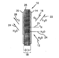
Electrochemical cells are energy conversion devices that are usually classified as either electrolytic cells or fuel cells. The proton exchange membrane electrolysis cell can function as a hydrogen generator by electrolytically decomposing water and generating hydrogen and oxygen gas. In FIG. 1, a portion of a prior art anode feed electrolytic cell is indicated generally at 10 and is hereinafter referred to as "
[0003]
An electrolytic cell system includes a number of individual cells arranged in a stack, and reaction water is supplied to the cells through input and output conduits formed in a stack structure. The cells in the stack are arranged sequentially, each having a membrane electrode assembly defined by a proton exchange membrane located between a cathode and an anode. The cathode, anode, or both may be gas diffusion electrodes that promote gas diffusion to the proton exchange membrane. Each membrane electrode assembly is defined by a structure configured to fluidly interact with a flow field adjacent to the membrane electrode assembly and to facilitate fluid movement and membrane hydration within each individual cell.
[0004]
The portion of the water containing hydrogen gas released from the cathode side of the cell is fed to a phase separator to separate the hydrogen gas from the water, thereby generally increasing the yield of hydrogen gas and increasing the overall cell Efficiency is improved. The removed hydrogen gas is supplied to a storage means such as a dryer, a cylinder, a tank or a similar container for removing a trace amount of water, or is used directly as a fuel.
[0005]
The following prior art documents are disclosed (for example, see Patent Documents 1 to 10).
[0006]
[Patent Document 1]
US Patent No. 5,389,264 [Patent Document 2]
US Patent No. 5,402,645 [Patent Document 3]
US Patent No. 6,179,986 [Patent Document 4]
US Pat. No. 6,309,521 [Patent Document 5]
US Patent No. 3,862,624 [Patent Document 6]
US Patent No. 4,950,371 [Patent Document 7]
US Pat. No. 5,037,518 [Patent Document 8]
US Patent No. 6,056,806 [Patent Document 9]
US Patent No. 6,383,361 [Patent Document 10]
US Pat. No. 6,461,487
[Problems to be solved by the invention]
Although existing electrolysis cell systems are suitable for their intended purpose, there is still a need for improvement, especially with respect to managing the separation of hydrogen gas from water. Further, there is a need for improved control of the water level in the phase separator during cell system operation.
[0008]
[Means for Solving the Problems]
The above disadvantages and disadvantages are overcome by a gas-liquid phase separator for an electrochemical cell system having an improved pressure control function of the phase separator. The phase separator includes a fluid inlet, a vapor outlet, a liquid outlet, and first and second valves arranged in fluid communication with the liquid outlet. Both valves are controllable in response to the liquid level of the phase separator and the pressure of the hydrogen system. Both valves are furthermore arranged in a configuration which flows parallel to one another.
[0009]
A method of controlling the liquid level of a phase separator includes sensing a volume of liquid in the phase separator, sensing a pressure of the hydrogen system, and selectively controlling a valve arranged in fluid communication with the phase separator. Opening to drain the liquid.
[0010]
BEST MODE FOR CARRYING OUT THE INVENTION
Those skilled in the art can appreciate and understand the above and other features from the following detailed description and drawings.
[0011]
In the figures, similar elements are provided with the same reference symbols between the figures.
[0012]
The present invention discloses a gas-liquid phase separator for an electrolytic cell system. The phase separator includes a system for managing the amount of water discharged from the phase separator. The system drains the gas-liquid phase separator through a valve arrangement arranged to flow parallel to one another. Each valve corresponds to a specific range of flow rates, which results in improved drainage and pressure stability of the separator. Having a unique operating range for each valve allows for a wide range of control of the system. Stabilization is achieved by improving the management of liquid discharge in the separator and maintaining the liquid level.
[0013]
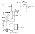
In FIG. 2, one embodiment of the hydrogen gas generation source is shown generally at 30 as an electrolysis cell system, hereinafter referred to as “
[0014]
The
[0015]
The cell stack 40 includes a plurality of cells similar to the
[0016]
A stream of hydrogen mixed with water is discharged from the cell stack 40 and supplied to a gas-liquid phase separation tank, which is a hydrogen /
[0017]
Water containing a trace amount of hydrogen is returned from the
[0018]
A hydrogen output sensor 64 is installed in
[0019]
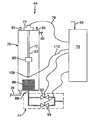
FIG. 3 is a schematic diagram of one embodiment of the
[0020]
Basically, the
[0021]
[0022]
The
[0023]
The
[0024]
In an example of the embodiment, the water
[0025]
The
[0026]
The first valve of the
[0027]
Information communication and drainage control of the
[0028]
In FIG. 4, an example of an embodiment of the
[0029]
The operation of the
[0030]
To prevent the
[0031]
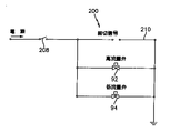
In FIG. 5, another embodiment of the cut-off function is shown as 200. In the
[0032]
Advantages of the valve device and the separator in which the valve device is installed include improved control of drainage during operation of the electrolytic cell system. Controlling the amount of drainage improves pressure stability and water level control within the separator. The shut-off function prevents the valve from opening when there is no water in the separator, thereby preventing the outflow of hydrogen from the liquid outlet of the separator. Further, the direct connection of the valve by the cut-off signal provides a redundant function that prevents operation of the valve when no electrical signal is transmitted. According to such an embodiment, the outflow of hydrogen from the liquid outlet of the separator is further prevented.
[0033]
Although the present invention has been described with reference to preferred embodiments, workers skilled in the art will recognize that various changes may be made and components may be replaced with equivalents without departing from the scope of the invention. Would. In addition, many modifications may be made to adapt a particular situation or material to the teachings of the invention without departing from the essential scope thereof. Therefore, it is intended that the invention not be limited to the particular embodiment disclosed, but that the invention will include all embodiments falling within the scope of the appended claims.
[Brief description of the drawings]
FIG. 1 is a schematic diagram of a conventional anode supply electrolysis cell.
FIG. 2 is a schematic diagram of an electrolysis cell system capable of generating hydrogen gas.
FIG. 3 is a schematic diagram of a system including a gas-liquid phase separator and various valves arranged in fluid communication therewith.
FIG. 4 is a schematic diagram of a solenoid valve.
FIG. 5 is a schematic diagram of one embodiment of a cut-off feature.
[Explanation of symbols]
10 cells, 12 reaction water, 14 oxygen electrode (anode), 15 hydrogen ion (proton), 16 oxygen gas, 18 power supply, 20 hydrogen electrode (cathode), 22 first part of water, 24 second part of water , 26 proton exchange membrane, 28 hydrogen gas, 30 systems, 32 water supply source, 34 conductivity sensor, 38 pump, 40 electrolytic cell stack, 42 power supply, 44 hydrogen / water separator (separator), 46 drying unit, 48 low pressure Hydrogen separator, 50 discharge means, 52 hydrogen outlet, 64 hydrogen output sensor, 66, 75 transducer, 70 container, 72 water level sensing unit, 74 valve device, 77 water level signal transmission device, 78 fluid inlet, 79 water level signal , 80 overflow port, 82 vapor outlet, 84 pressure release port, 86 filter, 88 liquid outlet, 90 float, 92 high flow valve, 93 stem, 94 low flow valve, 96 hydrogen system pressure signal, 97 solenoid valve, 98 valve shaft, 100 double arrow, 102 plug cock, 104 valve seat, 106 valve body, 108 water level signal transmitter / transmitter, 110, 210 Deadline signal, 200 deadline function, 208 deadline switch.
Claims (13)
電気化学電池と、
前記電気化学電池と流体交流する液体供給部と、
前記電気化学電池と電気交流するエネルギー源と、
前記電気化学電池と流体交流する気液相分離機と、
を備え、
前記気液相分離機は、前記気液相分離機の液体排出口と流体交流するよう配置された弁装置を有し、
前記弁装置は、各種範囲の流量について制御可能な少なくとも2つの弁を有すること、
を特徴とする気体生成システム。A gas generation system,
An electrochemical battery,
A liquid supply unit that performs fluid exchange with the electrochemical cell,
An energy source that electrically exchanges with the electrochemical cell;
A gas-liquid phase separator that fluidly exchanges with the electrochemical cell,
With
The gas-liquid phase separator has a valve device arranged to fluidly communicate with a liquid outlet of the gas-liquid phase separator,
The valve device has at least two valves that can be controlled for various ranges of flow rates;
A gas generation system characterized by the above.
前記弁は、前記気体生成システムの圧力と前記気液相分離機の液位に応答して選択的に制御可能であること、
を特徴とする気体生成システム。The gas generation system according to claim 1,
The valve is selectively controllable in response to the pressure of the gas generation system and the level of the gas-liquid phase separator;
A gas generation system characterized by the above.
前記弁は電磁弁であること、
を特徴とする気体生成システム。The gas generation system according to claim 1,
The valve is a solenoid valve;
A gas generation system characterized by the above.
流体取入口と、
蒸気排出口と、
液体排出口と、
前記液体排出口と流体交流するよう配置された第一の弁と、
前記液体排出口と流体交流するよう配置された第二の弁と、
を備え、
前記第一の弁は水素システムの圧力と前記気液相分離機の液位に応答して制御可能であり、
前記第二の弁は水素システムの圧力と前記気液相分離機の液位に応答して制御可能であり、
前記第二の弁は前記第一の弁と流れが平行となるように配置されていること、
を特徴とする気液相分離機。A gas-liquid phase separator,
A fluid inlet;
A steam outlet,
A liquid outlet,
A first valve arranged to be in fluid communication with the liquid outlet;
A second valve arranged in fluid communication with the liquid outlet;
With
The first valve is controllable in response to a hydrogen system pressure and a liquid level of the gas-liquid phase separator;
The second valve is controllable in response to a hydrogen system pressure and a liquid level of the gas-liquid phase separator;
The second valve is arranged so that the flow is parallel to the first valve,
Gas-liquid phase separator.
前記弁の一方または両方が電磁弁であることを特徴とする気液相分離機。It is a gas-liquid phase separator of Claim 4, Comprising:
A gas-liquid phase separator, wherein one or both of the valves are solenoid valves.
前記第一の弁は約110L/時から約120L/時の流量範囲で制御可能であることを特徴とする気液相分離機。It is a gas-liquid phase separator of Claim 4, Comprising:
The first valve is controllable in a flow rate range of about 110 L / hour to about 120 L / hour.
前記第一の弁は約105L/時から約113L/時の流量範囲で制御可能であることを特徴とする気液相分離機。It is a gas-liquid phase separator of Claim 4, Comprising:
The first valve is controllable in a flow rate range of about 105 L / hour to about 113 L / hour.
前記第二の弁は約8L/時から約15L/時の流量範囲で制御可能であることを特徴とする気液相分離機。It is a gas-liquid phase separator of Claim 4, Comprising:
The second valve is controllable in a flow rate range of about 8 L / hour to about 15 L / hour.
前記第二の弁は約9.3L/時から約13.5L/時の流量範囲で制御可能であることを特徴とする気液相分離機。It is a gas-liquid phase separator of Claim 4, Comprising:
A gas-liquid phase separator wherein the second valve is controllable in a flow rate range of about 9.3 L / hr to about 13.5 L / hr.
システム圧と前記気液相分離機の液位に応答して制御可能な第一の弁と、
前記第一の弁と平行に、これと流体交流するよう配置された第二の弁と、
を備え、
前記第二の弁はシステム圧と前記気液相分離機の液位に応答して制御可能であること、
を特徴とする気液相分離機用弁アセンブリ。A valve assembly for a gas-liquid phase separator of an electrochemical battery system,
A first valve controllable in response to system pressure and the level of the gas-liquid phase separator;
A second valve arranged in fluid communication with the first valve in parallel therewith;
With
The second valve is controllable in response to system pressure and liquid level of the gas-liquid phase separator;
A valve assembly for a gas-liquid phase separator.
前記気液相分離機の液体の量を感知するステップと、
前記気体の圧力を感知するステップと、
前記気液相分離機と流体交流するよう配置された弁を選択的に開き、液体を排出するステップと、
を含むことを特徴とする方法。A method for controlling a liquid level of a gas-liquid phase separator,
Sensing the amount of liquid in the gas-liquid phase separator;
Sensing the pressure of the gas;
Selectively opening a valve arranged for fluid exchange with the gas-liquid phase separator to discharge liquid;
A method comprising:
前記液体の量を感知する前記ステップは、
前記気液相分離機の液位を決定するステップと、
前記決定された液位を信号に変換するステップと、
前記信号を制御装置に送信するステップと、
を含むことを特徴とする方法。The method according to claim 11, wherein
The step of sensing the amount of the liquid includes:
Determining the liquid level of the gas-liquid phase separator;
Converting the determined liquid level into a signal;
Transmitting the signal to a control device;
A method comprising:
前記弁を選択的に開く前記ステップは、
前記気体の前記圧力を事前にプログラムされ、記憶された圧力値および前記気液相分離機の前記液体の量と比較するステップと、
前記気体の前記圧力、前記事前にプログラムされ記憶された圧力値、前記液体の量の比較に基づいて決定を下すステップと、
前記決定に基づいて弁を選択するステップと、
前記選択された弁に信号を送信するステップと、
を含むことを特徴とする方法。The method according to claim 11, wherein
The step of selectively opening the valve comprises:
Comparing the pressure of the gas with a pre-programmed and stored pressure value and the amount of the liquid in the gas-liquid phase separator;
Making a decision based on a comparison of the pressure of the gas, the pre-programmed and stored pressure value, the amount of the liquid;
Selecting a valve based on the determination;
Sending a signal to the selected valve;
A method comprising:
Applications Claiming Priority (1)
| Application Number | Priority Date | Filing Date | Title |
|---|---|---|---|
| US10/132,909 US6814841B2 (en) | 2002-04-24 | 2002-04-24 | Gas liquid phase separator with improved pressure control |
Publications (1)
| Publication Number | Publication Date |
|---|---|
| JP2004003003A true JP2004003003A (en) | 2004-01-08 |
Family
ID=29248864
Family Applications (1)
| Application Number | Title | Priority Date | Filing Date |
|---|---|---|---|
| JP2003113819A Pending JP2004003003A (en) | 2002-04-24 | 2003-04-18 | Gas-liquid phase separator with improved pressure control |
Country Status (3)
| Country | Link |
|---|---|
| US (2) | US6814841B2 (en) |
| JP (1) | JP2004003003A (en) |
| DE (1) | DE10317767A1 (en) |
Cited By (6)
| Publication number | Priority date | Publication date | Assignee | Title |
|---|---|---|---|---|
| JP2007231383A (en) * | 2006-03-02 | 2007-09-13 | Honda Motor Co Ltd | Hydrogen generation system |
| KR20140083764A (en) * | 2012-12-26 | 2014-07-04 | 현대모비스 주식회사 | Fuel cell exhaust system including multi-functional exhaust valve |
| JP2019511063A (en) * | 2015-12-21 | 2019-04-18 | ルクセンブルク・インスティテュート・オブ・サイエンス・アンド・テクノロジー・(エルアイエスティ) | Electrochemical reactor for controlling PH with small dimensions |
| JP2020183556A (en) * | 2019-05-07 | 2020-11-12 | 株式会社神鋼環境ソリューション | Hydrogen/oxygen generator and production method of hydrogen gas |
| KR102413307B1 (en) * | 2022-03-16 | 2022-06-27 | 주식회사 휴라이트 | Hydrogen genrating apparatus |
| EP4457184A4 (en) * | 2021-12-29 | 2025-12-31 | Ide Water Tech Ltd | RENEWABLE ENERGY SOURCE WITH PRESSURE-DRIVED FILTRATION PROCESSES AND SYSTEMS |
Families Citing this family (24)
| Publication number | Priority date | Publication date | Assignee | Title |
|---|---|---|---|---|
| US6814841B2 (en) * | 2002-04-24 | 2004-11-09 | Proton Energy Systems, Inc. | Gas liquid phase separator with improved pressure control |
| DE50209163D1 (en) * | 2002-07-01 | 2007-02-15 | Sfc Smart Fuel Cell Ag | Fluid separation device |
| EP1719197A4 (en) * | 2003-12-05 | 2008-08-06 | Proton Energy Sys Inc | HYDROGEN PRODUCTION SYSTEM AND ASSOCIATE PROCESS |
| US20050133377A1 (en) * | 2003-12-19 | 2005-06-23 | Noah Seidman | Streamlined Electrolyzer |
| US20060118428A1 (en) * | 2004-12-03 | 2006-06-08 | Baltrucki Justin D | System for generating hydrogen and method thereof |
| US7559978B2 (en) * | 2005-09-19 | 2009-07-14 | General Electric Company | Gas-liquid separator and method of operation |
| EP1977468A4 (en) * | 2005-12-23 | 2011-01-19 | Utc Power Corp | Non-circulating coolant pem fuel cell power plant with antifreeze back pressure air venting system |
| CA2534604A1 (en) * | 2006-01-30 | 2007-07-30 | Hy-Drive Technologies Ltd. | Gas liquid separator for hydrogen generating apparatus |
| US8168048B1 (en) * | 2006-02-03 | 2012-05-01 | M&R Consulting Services, Inc. | Carbon dioxide generation and dispensing device and method of production |
| WO2009142653A1 (en) * | 2008-05-22 | 2009-11-26 | Parker-Hannifin Corporation | Electrolytic cell stack with proton exchange membrane interlock sealing gasket |
| US7905946B1 (en) | 2008-08-12 | 2011-03-15 | The United States Of America As Represented By The Administrator Of The National Aeronautics And Space Administration | Systems and methods for separating a multiphase fluid |
| DE102009014744A1 (en) * | 2009-03-25 | 2010-09-30 | Daimler Ag | Method for the discontinuous emptying of a container |
| EP2418304A1 (en) * | 2010-08-09 | 2012-02-15 | Ion Science Limited | Hydrogen generation |
| CN102376964A (en) * | 2010-08-19 | 2012-03-14 | 上海清能燃料电池技术有限公司 | Method and device for producing and storing hydrogen |
| JP5437968B2 (en) * | 2010-10-14 | 2014-03-12 | 本田技研工業株式会社 | Water electrolysis system |
| CN103518007A (en) * | 2011-03-08 | 2014-01-15 | 氯工程公司 | Sulfuric acid electrolysis device and sulfuric acid electrolysis method |
| CN102732905A (en) | 2011-04-05 | 2012-10-17 | 本田技研工业株式会社 | Water electrolysis system and method of operating same |
| BR112014018043A8 (en) * | 2012-02-17 | 2017-07-11 | Sabic Innovative Plastics Ip Bv | APPARATUS FOR DETECTING A LIQUID LEVEL IN AN ELECTROLYTIC CELL, PROCESS FOR MAINTAINING A TARGET LIQUID LEVEL IN AN ELECTROLYTIC CELL, AND METHOD |
| ITUB20160614A1 (en) * | 2016-02-10 | 2017-08-10 | Elbi Int Spa | ASSEMBLY OF PRESSURE TRANSDUCER AND ANTI-ENLARGING DEVICE FOR AN APPARATUS, FOR EXAMPLE A WASHING MACHINE. |
| FR3062799B1 (en) * | 2017-02-10 | 2021-09-10 | Starklab | DEVICE FOR THE PRODUCTION AND TREATMENT OF GAS FLOWS THROUGH A VOLUME OF AUTOMATICALLY REGULATED LIQUID |
| GB2613128B (en) * | 2020-01-17 | 2024-08-21 | Itm Power Trading Ltd | Electrochemical cell plant |
| CN115652351B (en) * | 2022-11-03 | 2023-06-20 | 嘉庚创新实验室 | Asymmetric electrolytic water hydrogen production device |
| DE102023212354A1 (en) | 2023-12-07 | 2025-06-12 | Robert Bosch Gesellschaft mit beschränkter Haftung | Electrolysis system |
| CN118461022B (en) * | 2024-07-09 | 2024-09-10 | 福建德尔科技股份有限公司 | Perfluoro tripropylamine electrolytic tank capable of detecting liquid density |
Family Cites Families (25)
| Publication number | Priority date | Publication date | Assignee | Title |
|---|---|---|---|---|
| US3768234A (en) * | 1969-12-17 | 1973-10-30 | Universal Oil Prod Co | Venturi scrubber system including control of liquid flow responsive to gas flow rate |
| US3862624A (en) * | 1970-10-10 | 1975-01-28 | Patrick Lee Underwood | Oxygen-hydrogen fuel use for combustion engines |
| US4355652A (en) * | 1980-07-21 | 1982-10-26 | Perkins Lawrence B | Purging device |
| US4950371A (en) * | 1989-03-24 | 1990-08-21 | United Technologies Corporation | Electrochemical hydrogen separator system for zero gravity water electrolysis |
| US5037518A (en) * | 1989-09-08 | 1991-08-06 | Packard Instrument Company | Apparatus and method for generating hydrogen and oxygen by electrolytic dissociation of water |
| US5309720A (en) * | 1992-10-30 | 1994-05-10 | Q. B. Johnson Manufacturing, Inc. | Cryogenic system for processing a hydrocarbon gas stream |
| US5389264A (en) * | 1993-07-12 | 1995-02-14 | Zimpro Environmental Inc. | Hydraulic energy dissipator for wet oxidation process |
| US5632802A (en) * | 1995-03-03 | 1997-05-27 | Grgich; George R. | Apparatus and method of regenerating adsorbers for drying air |
| JP3035483B2 (en) * | 1995-11-27 | 2000-04-24 | スガ試験機株式会社 | Oxygen / hydrogen electrolysis gas generator |
| ZA9711050B (en) * | 1996-09-09 | 1999-05-07 | Quentin John Seaton Hartley | Management of a body of water |
| BR9605709A (en) * | 1996-11-26 | 1998-08-11 | Petroleo Brasileiro Sa | Drainage system for liquid storage tanks |
| US6576096B1 (en) * | 1998-01-05 | 2003-06-10 | Lynntech International, Ltd. | Generation and delivery device for ozone gas and ozone dissolved in water |
| US6287431B1 (en) * | 1997-03-21 | 2001-09-11 | Lynntech International, Ltd. | Integrated ozone generator system |
| AU6771398A (en) | 1997-03-21 | 1998-10-20 | Lynntech, Inc. | An integrated ozone generator system |
| DE19712993A1 (en) * | 1997-03-27 | 1998-10-01 | Asea Brown Boveri | Apparatus for heating and degassing water |
| WO1999062828A1 (en) * | 1998-05-29 | 1999-12-09 | Proton Energy Systems | Fluids management system for water electrolysis |
| US6179986B1 (en) * | 1998-11-05 | 2001-01-30 | Giner Electrochemical Systems Llc | Solid polymer electrolyte electrochemical oxygen control system with integral reactor feedback sensing |
| US6338786B1 (en) | 1999-07-16 | 2002-01-15 | Stuart Energy Systems Corporation | Gas-liquid separation method and apparatus in electrolytic cells |
| US6146518A (en) * | 1999-09-01 | 2000-11-14 | Stuart Energy Systems Inc. | Pressure differential control in an electrolytic cell |
| US6413297B1 (en) * | 2000-07-27 | 2002-07-02 | Northland Energy Corporation | Method and apparatus for treating pressurized drilling fluid returns from a well |
| US20040099614A1 (en) * | 2000-05-14 | 2004-05-27 | Jorg Lehmann | Method and device for the physicochemical treatment of fluid media |
| US6712944B2 (en) * | 2000-07-20 | 2004-03-30 | Proton Energy Systems, Inc. | Gas/liquid phase separator for electrolysis cell |
| US6814841B2 (en) * | 2002-04-24 | 2004-11-09 | Proton Energy Systems, Inc. | Gas liquid phase separator with improved pressure control |
| US20050045041A1 (en) * | 2003-08-29 | 2005-03-03 | Hechinger Glenn R. | Removable cartridge for swing-type adsorption system |
| US7338595B2 (en) * | 2003-11-13 | 2008-03-04 | Culligan International Company | Flow-through tank for water treatment |
-
2002
- 2002-04-24 US US10/132,909 patent/US6814841B2/en not_active Expired - Fee Related
-
2003
- 2003-04-17 DE DE2003117767 patent/DE10317767A1/en not_active Withdrawn
- 2003-04-18 JP JP2003113819A patent/JP2004003003A/en active Pending
-
2004
- 2004-07-28 US US10/900,623 patent/US7314509B2/en not_active Expired - Lifetime
Cited By (8)
| Publication number | Priority date | Publication date | Assignee | Title |
|---|---|---|---|---|
| JP2007231383A (en) * | 2006-03-02 | 2007-09-13 | Honda Motor Co Ltd | Hydrogen generation system |
| KR20140083764A (en) * | 2012-12-26 | 2014-07-04 | 현대모비스 주식회사 | Fuel cell exhaust system including multi-functional exhaust valve |
| KR101988054B1 (en) * | 2012-12-26 | 2019-06-11 | 현대모비스 주식회사 | Fuel cell exhaust system including multi-functional exhaust valve |
| JP2019511063A (en) * | 2015-12-21 | 2019-04-18 | ルクセンブルク・インスティテュート・オブ・サイエンス・アンド・テクノロジー・(エルアイエスティ) | Electrochemical reactor for controlling PH with small dimensions |
| JP2020183556A (en) * | 2019-05-07 | 2020-11-12 | 株式会社神鋼環境ソリューション | Hydrogen/oxygen generator and production method of hydrogen gas |
| JP7336254B2 (en) | 2019-05-07 | 2023-08-31 | 株式会社神鋼環境ソリューション | Hydrogen/oxygen generator and method for producing hydrogen gas |
| EP4457184A4 (en) * | 2021-12-29 | 2025-12-31 | Ide Water Tech Ltd | RENEWABLE ENERGY SOURCE WITH PRESSURE-DRIVED FILTRATION PROCESSES AND SYSTEMS |
| KR102413307B1 (en) * | 2022-03-16 | 2022-06-27 | 주식회사 휴라이트 | Hydrogen genrating apparatus |
Also Published As
| Publication number | Publication date |
|---|---|
| US20030201187A1 (en) | 2003-10-30 |
| US20050000800A1 (en) | 2005-01-06 |
| US7314509B2 (en) | 2008-01-01 |
| DE10317767A1 (en) | 2003-11-13 |
| US6814841B2 (en) | 2004-11-09 |
Similar Documents
| Publication | Publication Date | Title |
|---|---|---|
| US7314509B2 (en) | Gas liquid phase separator with improved pressure control | |
| CN112899712B (en) | Water electrolysis hydrogen production device and hydrogen production method | |
| US8419910B2 (en) | Electrolyzer cell stack system | |
| CN105862066B (en) | High-pressure proton membrane water electrolysis device and method | |
| JPH08327590A (en) | Carbon monoxide detector, organic compound detector and lower alcohol detector | |
| JP2000090954A5 (en) | ||
| EP0559653A1 (en) | Closed loop reactant/product management system for electrochemical galvanic energy devices | |
| CN109713350A (en) | The vanadium cell system of included electrolytic cell and the rebalancing method of vanadium cell liquid | |
| US9515339B2 (en) | Fuel cell system ion exchanger | |
| CN112856233A (en) | Pulse hydrogen supply system of proton exchange membrane fuel cell | |
| US20090081498A1 (en) | Catalyst reactor and fuel cell system comprising the same | |
| JP2011000566A (en) | Gas-liquid separator, apparatus for producing hydrogen, and fuel cell system | |
| CN114420977B (en) | A fuel cell anode system, control method and fuel cell | |
| US7691501B2 (en) | Fuel cell system and controlling method thereof | |
| CN110943242B (en) | A Porous Media Water Separator for Fuel Cells | |
| KR101322680B1 (en) | Gas-liquid separator for cascade type fuel cell | |
| CN221626402U (en) | Water electrolysis hydrogen production equipment | |
| HK1046936A1 (en) | Pressure control system in a water electrolytic cell | |
| CN222139303U (en) | Proton exchange membrane water electrolysis hydrogen production system | |
| CN100470908C (en) | Hydrogen-oxygen type proton exchange membrane fuel cell and its gas supply and drainage method | |
| KR102475163B1 (en) | Positive Air Pressure Damper Assembly | |
| CN101320819A (en) | Electro-chemistry oxygen-producing cell and apparatus | |
| US20080113249A1 (en) | Fuel cell system | |
| US20050202300A1 (en) | Electric power source comprising a fuel cell without discharge of matter to the outside and method for controlling such a power source | |
| CN108183254B (en) | Vanadium battery that saves energy and improves battery stability |