FR2776113A1 - Reed-Solomon error correction in optical disc reader - Google Patents
Reed-Solomon error correction in optical disc reader Download PDFInfo
- Publication number
- FR2776113A1 FR2776113A1 FR9803103A FR9803103A FR2776113A1 FR 2776113 A1 FR2776113 A1 FR 2776113A1 FR 9803103 A FR9803103 A FR 9803103A FR 9803103 A FR9803103 A FR 9803103A FR 2776113 A1 FR2776113 A1 FR 2776113A1
- Authority
- FR
- France
- Prior art keywords
- sep
- register
- output
- alpha
- polynomial
- Prior art date
- Legal status (The legal status is an assumption and is not a legal conclusion. Google has not performed a legal analysis and makes no representation as to the accuracy of the status listed.)
- Pending
Links
Classifications
-
- H—ELECTRICITY
- H03—ELECTRONIC CIRCUITRY
- H03M—CODING; DECODING; CODE CONVERSION IN GENERAL
- H03M13/00—Coding, decoding or code conversion, for error detection or error correction; Coding theory basic assumptions; Coding bounds; Error probability evaluation methods; Channel models; Simulation or testing of codes
- H03M13/03—Error detection or forward error correction by redundancy in data representation, i.e. code words containing more digits than the source words
- H03M13/05—Error detection or forward error correction by redundancy in data representation, i.e. code words containing more digits than the source words using block codes, i.e. a predetermined number of check bits joined to a predetermined number of information bits
- H03M13/13—Linear codes
- H03M13/15—Cyclic codes, i.e. cyclic shifts of codewords produce other codewords, e.g. codes defined by a generator polynomial, Bose-Chaudhuri-Hocquenghem [BCH] codes
- H03M13/151—Cyclic codes, i.e. cyclic shifts of codewords produce other codewords, e.g. codes defined by a generator polynomial, Bose-Chaudhuri-Hocquenghem [BCH] codes using error location or error correction polynomials
-
- H—ELECTRICITY
- H03—ELECTRONIC CIRCUITRY
- H03M—CODING; DECODING; CODE CONVERSION IN GENERAL
- H03M13/00—Coding, decoding or code conversion, for error detection or error correction; Coding theory basic assumptions; Coding bounds; Error probability evaluation methods; Channel models; Simulation or testing of codes
- H03M13/65—Purpose and implementation aspects
- H03M13/6502—Reduction of hardware complexity or efficient processing
-
- H—ELECTRICITY
- H03—ELECTRONIC CIRCUITRY
- H03M—CODING; DECODING; CODE CONVERSION IN GENERAL
- H03M13/00—Coding, decoding or code conversion, for error detection or error correction; Coding theory basic assumptions; Coding bounds; Error probability evaluation methods; Channel models; Simulation or testing of codes
- H03M13/65—Purpose and implementation aspects
- H03M13/6508—Flexibility, adaptability, parametrability and configurability of the implementation
- H03M13/6513—Support of multiple code types, e.g. unified decoder for LDPC and turbo codes
-
- G—PHYSICS
- G11—INFORMATION STORAGE
- G11B—INFORMATION STORAGE BASED ON RELATIVE MOVEMENT BETWEEN RECORD CARRIER AND TRANSDUCER
- G11B20/00—Signal processing not specific to the method of recording or reproducing; Circuits therefor
- G11B20/10—Digital recording or reproducing
- G11B20/18—Error detection or correction; Testing, e.g. of drop-outs
- G11B20/1806—Pulse code modulation systems for audio signals
- G11B20/1809—Pulse code modulation systems for audio signals by interleaving
-
- G—PHYSICS
- G11—INFORMATION STORAGE
- G11B—INFORMATION STORAGE BASED ON RELATIVE MOVEMENT BETWEEN RECORD CARRIER AND TRANSDUCER
- G11B20/00—Signal processing not specific to the method of recording or reproducing; Circuits therefor
- G11B20/10—Digital recording or reproducing
- G11B20/18—Error detection or correction; Testing, e.g. of drop-outs
- G11B20/1833—Error detection or correction; Testing, e.g. of drop-outs by adding special lists or symbols to the coded information
- G11B2020/1836—Error detection or correction; Testing, e.g. of drop-outs by adding special lists or symbols to the coded information using a Reed Solomon [RS] code
Abstract
Description
L'invention concerne un dispositif de correction d'erreurs de type
Reed-Solomon et un appareil de lecture optique comportant un tel dispositif.The invention relates to a device for correcting errors of the type
Reed-Solomon and an optical reading apparatus comprising such a device.
L'invention s'applique notamment dans le cadre de la correction d'erreur dans des appareils de lecture de disques optiques ou magnéto-optiques.The invention is particularly applicable in the context of error correction in optical or magneto-optical disk reading devices.
La correction d'erreur de type Reed-Solomon ('RS') est utilisée dans de nombreuses applications. Une des applications les plus répandues est le disque compact ('CD'). Dans l'avenir, les codes RS seront également employés dans le cadre des disques dits 'DVD'. Reed-Solomon error correction ('RS') is used in many applications. One of the most widespread applications is the compact disc ('CD'). In the future, RS codes will also be used in the so-called 'DVD' discs.
Bien qu'ayant été développés dans les années 60, les codes RS n'ont été employés dans des appareils pour le grand public que depuis le début des années 80. Ceci est du en partie au fait que cette correction d'erreur exige une puissance de calcul relativement importante, donc coûteuse. La correction requiert par exemple la multiplication et la division de polynômes, ainsi que la détermination des racines de polynômes. Dans ce cadre, il est intéressant de réduire la complexité des circuits mis en oeuvre dans cette correction, en vue d'un réduire le coût et d'en augmenter la fiabilité. Although developed in the 1960s, RS codes have only been used in consumer devices since the early 1980s. This is partly because this error correction requires power relatively important calculation, so expensive. The correction requires, for example, the multiplication and division of polynomials as well as the determination of the polynomial roots. In this context, it is interesting to reduce the complexity of the circuits implemented in this correction, in order to reduce the cost and increase reliability.
L'invention a pour objet un dispositif de correction d'erreurs de type
Reed-Solomon comportant.The subject of the invention is a device for correcting errors of the type
Reed-Solomon featuring.
- un générateur de syndromes,
- des moyens de détermination des coefficients des polynômes de localisation et d'évaluation d'erreur,
- des moyens de détermination de la position et de la valeur d'erreurs, lesdits moyens de détermination des coefficients étant aptes à mettre en oeuvre l'algorithme étendu d'Euclide,
caractérisé en ce que
les moyens de détermination des coefficients sont agencés pour réaliser le produit du polynôme de localisation d'erreur et d'un polynôme d'effacement pour l'obtention d'un nouveau polynôme de localisation d'erreur.- a generator of syndromes,
means for determining the coefficients of the localization and error evaluation polynomials,
means for determining the position and the error value, said means for determining the coefficients being able to implement the extended Euclidean algorithm,
characterized in that
the coefficient determining means are arranged to produce the product of the error localization polynomial and an erasure polynomial for obtaining a new error localization polynomial.
L'algorithme étendu d'Euclide nécessite la multiplication de polynômes. Selon l'invention, cette possibilité est mise a profit pour réaliser d'autres multiplications de polynomes nécessaires pour la correction d'erreur, ce qui permet de simplifier les autres parties du dispositif de correction. The extended Euclidean algorithm requires the multiplication of polynomials. According to the invention, this possibility is used to make other multiplications of polynomials necessary for the error correction, which makes it possible to simplify the other parts of the correction device.
Selon un mode de réalisation de l'invention, les moyens de détermination des coefficients sont agencés pour réaliser le produit d'un polynôme de syndromes par le polynôme d'effacement. According to one embodiment of the invention, the means for determining the coefficients are arranged to produce the product of a polynomial of syndromes by the erasure polynomial.
L'invention a aussi pour objet un lecteur de disques optiques comportant le dispositif de correction. The invention also relates to an optical disk drive comprising the correction device.
D'autres avantages et caractéristiques de l'invention apparaîtront à travers la description d'un exemple de réalisation non limitatif décrit à l'aide des figures parmi lesquelles:
la figure 1 est un diagramme illustrant le codage RS d'un bloc de données de type CD,
la figure 2 est un diagramme illustrant le codage RS d'un bloc de données de type DVD,
la figure 3 est un diagramme bloc du dispositif conforme au présent exemple de réalisation,
la figure 4 est un diagramme bloc illustrant les échanges de données en mode dit mode 'DVD',
la figure 5 est un diagramme bloc illustrant les échanges de données en mode dit mode 'CD',
la figure 6 est un diagramme illustrant le stockage d'un paquet de données de type DVD dans une mémoire du dispositif conforme à l'invention,
la figure 7 est un diagramme illustrant l'organisation des données à l'intérieur d'une mémoire du dispositif conforme a l'invention,
la figure 8 est un schéma des deux registres de coefficients de polynômes utilisés par le résolveur d'équations des figures 3 à 5,
la figure 9 est un diagramme illustrant la connexion de cellules à registres dans un circuit résolveur d'équations utilisé dans le décodage Reed
Solomon,
la figure 10 est un diagramme bloc d'une cellule de la figure 9,
la figure 11 est un diagramme bloc de la cellule de la figure 10 dans une première configuration,
la figure 12 est un diagramme bloc de la cellule de la figure 10 dans une seconde configuration,
la figure 13 est un diagramme bloc de la cellule de la figure 10 dans une troisième configuration,
la figure 14 est un diagramme bloc de plusieurs cellules de la figure 10 placées en série selon une première configuration,
la figure 15 est un diagramme bloc de plusieurs cellules de la figure 10 placées en série selon une deuxième configuration,
la figure 16 est un diagramme bloc d'un lecteur de disque optique comportant un dispositif conforme à l'invention.Other advantages and characteristics of the invention will become apparent through the description of a nonlimiting exemplary embodiment described with the help of the figures among which:
FIG. 1 is a diagram illustrating the RS coding of a data block of the CD type,
FIG. 2 is a diagram illustrating the RS coding of a DVD type data block,
FIG. 3 is a block diagram of the device according to the present embodiment,
FIG. 4 is a block diagram illustrating the data exchanges in so-called 'DVD' mode,
FIG. 5 is a block diagram illustrating the data exchanges in mode called 'CD' mode,
FIG. 6 is a diagram illustrating the storage of a DVD type data packet in a memory of the device according to the invention,
FIG. 7 is a diagram illustrating the organization of the data inside a memory of the device according to the invention,
FIG. 8 is a diagram of the two polynomial coefficient registers used by the equation resolver of FIGS. 3 to 5,
Fig. 9 is a diagram illustrating the connection of register cells in a resolver circuit of equations used in Reed decoding.
Solomon,
FIG. 10 is a block diagram of a cell of FIG. 9,
FIG. 11 is a block diagram of the cell of FIG. 10 in a first configuration,
FIG. 12 is a block diagram of the cell of FIG. 10 in a second configuration,
FIG. 13 is a block diagram of the cell of FIG. 10 in a third configuration,
FIG. 14 is a block diagram of several cells of FIG. 10 placed in series in a first configuration,
FIG. 15 is a block diagram of several cells of FIG. 10 placed in series in a second configuration,
Figure 16 is a block diagram of an optical disk drive comprising a device according to the invention.
Le standard CD ('Compact Disc') préconise l'utilisation d'un code correcteur d'erreur Reed-Solomon à entrelacement croisé ("Cross Interleaved
Reed-Solomon error-correction code" ou CIRC). La mise en oeuvre de ce code comporte le partage de chaque échantillon digital de 16 bits à coder en deux symboles de 8 bits.The CD ('Compact Disc') standard recommends the use of a Cross Interleaved Reed-Solomon error correction code.
Reed-Solomon error-correction code "or CIRC) The implementation of this code involves the sharing of each 16-bit digital sample to be encoded into two 8-bit symbols.
La figure 1 illustre plus particulièrement la structure d'un bloc de données (trame) conformément au standard CD. FIG. 1 more particularly illustrates the structure of a data block (frame) according to the CD standard.
Les échantillons à coder sont stockés dans une mémoire vive et présentés à l'encodeur sous la forme de blocs de vingt-quatre symboles (correspondant à six échantillons de 16 bits pour chacun des deux canaux). The samples to be encoded are stored in a random access memory and presented to the encoder in the form of blocks of twenty-four symbols (corresponding to six 16-bit samples for each of the two channels).
Selon une première étape, ces symboles sont entrelacés. en retardant de deux échantillons les échantillons pairs et en intervertissant les connexions vers la première partie de l'encodeur, dit encodeur C2. L'encodeur C2 détermine quatre symboles de parité de 8 bits (dits symboles Q) à partir du mot de code de 24 symboles, et insère les quatre symboles de parité parmi les autres symboles. En résultent 28 symboles. L'encodeur C2 est donc un encodeur (28,24).In a first step, these symbols are intertwined. delaying the even samples by two samples and interchanging the connections to the first part of the encoder, called the C2 encoder. Encoder C2 determines four 8-bit parity symbols (called Q symbols) from the 24-symbol code word, and inserts the four parity symbols among the other symbols. The result is 28 symbols. The encoder C2 is therefore an encoder (28,24).
Les symboles sont transmis au second encodeur, appelé encodeur
C2, à travers 28 lignes à retard de longueur inégale, multiples de quatre blocs, de façon à répartir les 28 symboles d'un mot sur 28 blocs différents. Ces 28 blocs seront ensuite entrelacés avec d'autres blocs, à raison d'un bloc parmi les 28 blocs pour trois autres blocs. L'encodeur ajoute quatre symboles de parité de 8 bits supplémentaires (symboles P) à chaque bloc, portant le total à 32 symboles. L'encodeur C1 est donc un encodeur (32,28). Ces symboles sont utilisés, après un traitement supplémentaire consistant à inverser les symboles de parité et à retarder les symboles pairs, pour former un paquet de données.The symbols are transmitted to the second encoder, called encoder
C2, through 28 lines of delay of unequal length, multiples of four blocks, so as to distribute the 28 symbols of a word on 28 different blocks. These 28 blocks will then be interlaced with other blocks, one block among the 28 blocks for another three blocks. The encoder adds four additional 8-bit parity symbols (P symbols) to each block, bringing the total to 32 symbols. The encoder C1 is therefore an encoder (32,28). These symbols are used after further processing of inverting the parity symbols and delaying the even symbols to form a data packet.
A ces données s'ajoutent un certain nombre d'informations de contrôle, qui ne seront pas détaillées ici. Pour plus d'informations sur le codage des données, on se reportera entre autres au chapitre 9 de l'ouvrage 'Digital
Audio and Compact Disc Technology', troisième édition 1995, Sony Service
Centre Europe, ou encore à l'ouvrage 'Reed-Solomon Codes and their applications', Wicker/Bhagarva, IEEE Press 1994, chapitre 4.To these data are added a certain number of control information, which will not be detailed here. For more information on the coding of data, see chapter 9 of the book 'Digital'.
Audio and Compact Disc Technology ', Third Edition 1995, Sony Service
Center Europe, or 'Reed-Solomon Codes and their applications', Wicker / Bhagarva, IEEE Press 1994, Chapter 4.
La correction des paquets de type CD nécessite donc deux passes à travers un décodeur Reed-Solomon, la première pour le décodage C1 et la seconde pour le décodage C2, avec un désentrelacement entre les deux passes. Correction of CD type packets therefore requires two passes through a Reed-Solomon decoder, the first for decoding C1 and the second for decoding C2, with deinterlacing between the two passes.
Si la capacité de correction de C1 est dépassée (en fonction du nombre d'effacements et d'erreurs à corriger), les 28 symboles (32 moins les quatre symboles de parité P) sont marqués de drapeaux d'effacement ('erasure flags') et ne sont pas corrigés. Lors du désentrelacement, ces 28 symboles seront répartis sur 28 blocs. If the correction capacity of C1 is exceeded (depending on the number of erasures and errors to be corrected), the 28 symbols (32 minus the four P parity symbols) are marked with 'erasure flags' ) and are not corrected. During deinterlacing, these 28 symbols will be spread over 28 blocks.
Si la capacité de correction de C2 est dépassée, les 24 symboles (28 moins les quatre symboles de parité Q) sont marqués d'un drapeau et ne sont pas corrigés. If the correction capacity of C2 is exceeded, the 24 symbols (28 minus the four Q parity symbols) are flagged and not corrected.
La correction d'erreur utilisée dans le cadre du DVD ('Digital
VideoNersatile Disc') est différente: un bloc de 192 lignes de 172 symboles (un symbole = 1 octet) est associé verticalement à un code Reed-Solomon dit externe ('PO') composé de 16 lignes de 172 octets. puis horizontalement à un code Reed-Solomon dit interne ('PI') composé de 208 lignes de 10 octets. Le code interne est calculé à partir du bloc de données et å partir du code externe. L'ensemble donne un bloc de 208 lignes de 182 octets. Les 16 lignes du code externe sont ensuite insérées de manière entrelacée parmi les 192 lignes restantes.The error correction used in the DVD ('Digital
VideoNersatile Disc ') is different: a block of 192 rows of 172 symbols (one symbol = 1 byte) is vertically associated with an external Reed-Solomon code (' PO ') composed of 16 lines of 172 bytes. then horizontally to a so-called internal Reed-Solomon code ('PI') consisting of 208 lines of 10 bytes. The internal code is calculated from the data block and from the external code. The set gives a block of 208 rows of 182 bytes. The 16 lines of the outer code are then inserted interleaved among the remaining 192 lines.
La structure d'un paquet de données conforme au standard DVD est illustrée par la figure 2. The structure of a data packet conforming to the DVD standard is illustrated in Figure 2.
La figure 3 est un diagramme bloc du dispositif selon le présent exemple de réalisation. Figure 3 is a block diagram of the device according to the present embodiment.
Un circuit 1 comporte en série, pour les besoins de la correction d'erreur proprement dite, un générateur de syndromes 2, un résolveur d'équations 3 et un correcteur 4. A circuit 1 comprises in series, for the purposes of error correction itself, a syndrom generator 2, an equation resolver 3 and a corrector 4.
Une mémoire vive 5 externe au circuit 1, par exemple du type
SRAM. sert à stocker certains paquets de données brutes à corriger et les données corrigées. Une mémoire vive interne 6, utilisée uniquement en mode
CD, est destinée à stocker des résultats de décodage intermédiaire. Ceci évite avantageusement un accès trop fréquent à la mémoire externe 5.A RAM 5 external to the circuit 1, for example of the type
SRAM. is used to store certain raw data packets to be corrected and the corrected data. An internal RAM 6, used only in mode
CD, is intended to store intermediate decoding results. This advantageously avoids too frequent access to the external memory 5.
Le circuit 1 comporte en outre quatre multiplexeurs qui, selon leur état, définissent le mode de fonctionnement CD ou le mode de fonctionnement
DVD, ainsi que les diverses étapes dans le cadre de chaque mode. Un premier multiplexeur 7 sélectionne, à l'entrée du générateur de syndromes 2, soit les données en provenance de la SRAM 5, soit les données en provenance de la mémoire 6. Un second multiplexeur 8 sélectionne à l'entrée de la mémoire 6 soit les données en provenance de la SRAM 5, soit les données entrantes en provenance de l'extérieur du circuit (ligne I sur la figure 1). Un troisiéme multiplexeur 9 sélectionne, à l'entrée du correcteur 4, soit des données en provenance de la SRAM 5, soit des données en provenance de la mémoire 6, soit des données en provenance du résolveur d'équations 3. Un quatrième multiplexeur 10 alimente la SRAM 5, soit par des données corrigées en provenance du correcteur 4, soit par des données entrantes (I).The circuit 1 further comprises four multiplexers which, depending on their state, define the operating mode CD or the operating mode
DVD, as well as the various steps under each mode. A first multiplexer 7 selects, at the input of the syndrom generator 2, either the data coming from the SRAM 5 or the data coming from the memory 6. A second multiplexer 8 selects at the input of the memory 6 either the data coming from the SRAM 5, ie the incoming data coming from outside the circuit (line I in FIG. 1). A third multiplexer 9 selects, at the input of the corrector 4, either data coming from the SRAM 5, or data coming from the memory 6, or data coming from the resolver of equations 3. A fourth multiplexer 10 feeds the SRAM 5, either by corrected data from the corrector 4 or by incoming data (I).
La mémoire 5 est utilisée pour stocker les blocs de type DVD, les drapeaux d'erreur ou d'effacements associés à ces blocs avant ou après une passe de correction. les blocs C2 de type CD dans un but d'entrelacement avant correction, des drapeaux d'erreur qui y sont associés, les blocs C1 corrigés et diverses données de synchronisation. The memory 5 is used to store the DVD type blocks, the error or erase flags associated with these blocks before or after a correction pass. CD-type blocks C2 for pre-correction interleaving purposes, error flags associated therewith, corrected C1 blocks, and various synchronization data.
Chaque passe de correction d'erreur Reed-Solomon effectuée par le circuit 1 peut être résumée comme suite, que ce soit en mode CD ou DVD. Each Reed-Solomon error correction pass made by circuit 1 can be summarized as a continuation, whether in CD or DVD mode.
Etape 1. Calcul des syndromes S, du polynôme d'effacement E(z) et du syndrome modifié T(z)

ou r est le nombre de symboles de parité dans un mot de code, et où
![]()
where r is the number of parity symbols in a codeword, and where
![]()
où n est le nombre de symboles d'un mot de code, où les coefficients r sont tels que r(x)= rn ~ I rn -2 t rn - 2 zn - -.. ~r...+rO où r(x) est un mot de code reçu, et où ai est une racine de g(z), polynôme générateur,
![]()
![]()
où aJk est la position d'un effacement k et ou e est le nombre d'effacements,
T(z)=S(z)E(z) mod z (3)
où t est un paramètre du code RS.where aJk is the position of an erase k and where e is the number of erasures,
T (z) = S (z) E (z) mod z (3)
where t is a parameter of the RS code.
Remarque: le paramètre r dépend de la correction en cours. C'est le nombre de syndromes à calculer pour chaque mot de code. II est égal au nombre de symboles de parité dans le mot de code à corriger: 4 et 4 pour les deux codages C1 et C2 du disque compact, 10 et 16 pour les codages interne et externe du DVD. Note: The r parameter depends on the current correction. This is the number of syndromes to calculate for each code word. It is equal to the number of parity symbols in the code word to be corrected: 4 and 4 for the two codings C1 and C2 of the compact disc, 10 and 16 for the internal and external encodings of the DVD.
Etape 2. Mettre en oeuvre l'algorithme d'Euclide étendu pour calculer le polynôme de localisation d'erreur ,\(z) et le polynôme d'évaluation d'erreur Q(z), et calculer le nouveau polynôme de localisation d'erreur '(z). où
Y(z) =A(z)E(z) mod z (4)
Etape 3. Mettre en oeuvre l'algorithme de Chien pour déterminer les racines du polynôme de localisation d'erreur. Les racines de ce polynôme indiquent les positions des erreurs et des effacements dans les symboles reçus. Mettre en oeuvre l'algorithme de Forney pour déterminer les valeurs des erreurs et des effacements à partir des racines du polynôme de localisation d'erreur, de la dérivée du polynôme de localisation d'erreur et du polynôme d'évaluation d'erreur.Step 2. Implement the extended Euclidean algorithm to compute the error localization polynomial, \ (z) and the error evaluation polynomial Q (z), and compute the new localization polynomial of error '(z). or
Y (z) = A (z) E (z) mod z (4)
Step 3. Implement the Dog algorithm to determine the roots of the error localization polynomial. The roots of this polynomial indicate the positions of errors and deletions in the received symbols. Implement the Forney algorithm to determine the error and erase values from the roots of the error localization polynomial, the derivative of the error localization polynomial, and the error evaluation polynomial.
Etape 4. Vérifier le processus de décodage et corriger les symboles reçus. Step 4. Check the decoding process and correct the received symbols.
Les algorithmes mentionnés sont, en soi, connus par ailleurs. On se référera notamment à l'ouvrage 'Reed-Solomon Codes and their Applications', édité par S.B. Wicker et V.K. Bhagarva, IEEE Press 1994, en ce qui concerne des Implémentations de l'algorithme d'Euclide et les algorithmes de Chien et de
Forney, et de manière générale, la théorie mathématique des codes Reed
Solomon. II existe d'ailleurs dans la littérature d'autres algorithmes pour réaliser chacune des étapes.The algorithms mentioned are, in themselves, known elsewhere. Reference will be made in particular to Reed-Solomon Codes and their Applications, edited by SB Wicker and VK Bhagarva, IEEE Press 1994, with respect to implementations of the Euclidean algorithm and the algorithms of Dog and
Forney, and in general, the mathematical theory of Reed codes
Solomon. There are other algorithms in the literature to carry out each of the steps.
Dans ce qui suit, on décrira dans un premier temps le fonctionnement du dispositif dans chaque mode, DVD ou CD, puis dans un deuxiéme temps, on s'attachera à décrire plus en détail l'implémentation matérielle de certains aspects du décodeur Reed-Solomon, en particulier le résolveur d'équations 3. In what follows, we will first describe the operation of the device in each mode, DVD or CD, then in a second time, we will attempt to describe in more detail the hardware implementation of certain aspects of the Reed-Solomon decoder. , in particular the resolver of equations 3.
- Décodage DVD
Le fonctionnement en mode DVD est illustré par la figure 4. Par rapport au schéma général de la figure 31 les parties du circuit 1 non concernées par le fonctionnement en mode DVD ont été effacées.- DVD decoding
The operation in DVD mode is illustrated in FIG. 4. With respect to the general diagram of FIG. 31, the parts of circuit 1 not concerned with operation in DVD mode have been erased.
(a) Code interne (Pl) - Première passe
Les données entrantes sont stockées dans un premier temps dans la
SRAM 5 en transitant par le multiplexeur 10. La figure 6 montre la façon dont les blocs sont stockés dans la SRAM 5. Ces données sont composées de deux blocs de 208*182 octets Chaque bloc est accompagné de 208*23 octets d'effacement. Chaque bit d'effacement Indique pour un symbole d'un bloc si ce symbole est à considérer comme sûr ou non. Cette information est utilisée ensuite au cours de la correction d'erreur Reed-Solomon. Ces bits d'effacement sont déterminés de façon connue en soi par un ensemble extérieur au circuit 1. Selon le présent exemple de réalisation. cet ensemble extérieur vérifie la présence de la donnée dans une table de démodulation numérique.(a) Internal Code (Pl) - First pass
Incoming data is stored first in the
SRAM 5 passing through the multiplexer 10. Figure 6 shows how the blocks are stored in the SRAM 5. These data are composed of two blocks of 208 * 182 bytes Each block is accompanied by 208 * 23 bytes of erasure. Each erase bit Indicates for a symbol of a block whether this symbol is to be considered safe or not. This information is then used during the Reed-Solomon error correction. These erasure bits are determined in a manner known per se by an assembly outside circuit 1. According to the present embodiment. this external set checks the presence of the data in a digital demodulation table.
Dans un premier temps, le circuit procède au décodage du code RS interne PI. Le bloc de données ou symboles, ainsi que les bits d'effacement sont lus ligne par ligne dans la SRAM 5 et transférés au générateur de syndromes 2. Celui-ci détermine pour chaque ligne (chaque mot de code) le polynôme S(z) et le polynôme d'effacement E(z), tels que définis précédemment. In a first step, the circuit decodes the internal RS code PI. The data block or symbols, as well as the erasure bits are read line by line in the SRAM 5 and transferred to the syndrom generator 2. This determines for each line (each codeword) the polynomial S (z) and the erasure polynomial E (z), as defined above.
Pratiquement, les syndromes Sj sont calculés de la façon suivante:
![]()
![]()
où T est la matrice associée au polynôme générateur G(z). Selon le présent exemple, G(z) = z8 T z4 - z3 Z -1. Dans ce cas, la matrice T est:
0 O O O O O 0 11
1 0 0 0 0 0 0 0
0 1 0 0 0 0 0 1
0 0 1 0 0 0 0 1
0 0 0 1 0 0 0 1 10 0 0 0 1 0 0 0
10 O O 0 O i 0 O
0 0 0 0 0 0 1 0
Les calculs des Sj syndromes sont effectués par le générateur 2, à l'aide de j registres rebouclés chacun sur leur entrée respective à travers un
n multiplicateur par T et un additionneur. Les syndromes Sj constituent les coefficients du polynôme S(z).where T is the matrix associated with the generator polynomial G (z). According to the present example, G (z) = z8 T z4 - z3 Z -1. In this case, the matrix T is:
0 OOOOO 0 11
1 0 0 0 0 0 0 0
0 1 0 0 0 0 0 1
0 0 1 0 0 0 0 1
0 0 0 1 0 0 0 1 10 0 0 0 1 0 0 0
10 OO 0 O i 0 O
0 0 0 0 0 0 1 0
The Sj syndromes are calculated by the generator 2, using j registers each looped back to their respective input through a
n multiplier by T and an adder. The syndromes Sj constitute the coefficients of the polynomial S (z).
Dans le cas du décodage DVD, chaque ligne transférée comporte donc 182 octets de données, chaque octet représentant un symbole, ainsi que 182 bits d'effacement, un pour chaque symbole. Le code interne PI étant constitué de 10 symboles de correction, 10 syndromes sont calculés. Le générateur 2 détermine également à partir des bits d'effacement les coefficients Ej du polynôme d'effacement E(z) et les stocke dans un registre approprié. In the case of DVD decoding, each line transferred therefore comprises 182 bytes of data, each byte representing a symbol, as well as 182 erasure bits, one for each symbol. The internal code PI consisting of 10 correction symbols, 10 syndromes are calculated. The generator 2 also determines from the erase bits the coefficients Ej of the erase polynomial E (z) and stores them in a suitable register.
S'il y a plus de dix effacements dans une ligne, la correction n'est pas possible et le mot de code est marqué comme erroné. L'état erroné d'un mot de code est inscrit dans la mémoire SRAM (Figure 6), sous la forme d'un bit ('Inner 1 Error Flag'). If there are more than ten erasures in a line, the correction is not possible and the codeword is marked as erroneous. The erroneous state of a code word is written in the SRAM memory (FIG. 6) in the form of a bit ('Inner 1 Error Flag').
Les coefficients de S(z), et le cas échéant de E(z), sont transmis au résolveur d'équations 3. The coefficients of S (z), and if necessary of E (z), are transmitted to the resolver of equations 3.
Si un polynôme d'effacement E(z) existe (au moins un effacement), alors le circuit 3 calcule le polynôme T(z), produit de E(z) par S(z), puis met en oeuvre l'algorithme étendu d'Euclide pour déterminer en même temps le polynôme de localisation d'erreur #(z) et le polynôme d'évaluation d'erreur #(z). If an erase polynomial E (z) exists (at least one erasure), then the circuit 3 calculates the polynomial T (z), produced by E (z) by S (z), and then implements the extended algorithm of Euclid to determine at the same time the error localization polynomial # (z) and the error evaluation polynomial # (z).
Si aucun effacement n'existe, alors la détermination de #(z) et de
A(z) est effectuée directement à partir de S(z) (en ce qui concerne les calculs, on prendra dans ce cas E(z)=1). If no deletion exists, then the determination of # (z) and
A (z) is carried out directly from S (z) (as far as calculations are concerned, we will take E (z) = 1).
Le circuit 3 détermine également, le cas échéant, Y(Z). The circuit 3 also determines, if necessary, Y (Z).
La structure et le fonctionnement du circuit 3 seront vus en détail plus loin. The structure and operation of circuit 3 will be seen in detail later.
Le correcteur 4 exécute de façon connue les algorithmes de Chien et Forney. Corrector 4 executes in a known manner the algorithms of Dog and Forney.
Ce correcteur disposera donc finalement des données suivantes:
- les positions des erreurs dans le mot de code traité,
- les valeurs de ces erreurs,
- le nombre d'effacements.This corrector will thus finally have the following data:
the positions of the errors in the processed code word,
- the values of these errors,
- the number of erasures.
Les erreurs dans le mot de code sont corrigés en conséquence. The errors in the codeword are corrected accordingly.
Pour ce faire, le circuit correcteur 4 (figure 4) lit le mot de code à corriger dans la mémoire SRAM 5 et les positions et valeurs des erreurs à partir du circuit 3.To do this, the corrector circuit 4 (FIG. 4) reads the code word to be corrected in the SRAM memory 5 and the positions and values of the errors from the circuit 3.
Le correcteur 4 Inscrit le mot de code corrigé dans la SRAM 5, à l'emplacement du mot de code initial. Les multiplexeurs 9 et 10 sont commandés en conséquence. Si la capacité du code RS est dépassée, le correcteur inscrit un drapeau d'indication d'erreur (Référence 'Inner 1 Error Flags' de la figure 6).Corrector 4 Inserts the corrected codeword in SRAM 5 at the location of the initial code word. The multiplexers 9 and 10 are controlled accordingly. If the capacity of the RS code is exceeded, the corrector writes an error indication flag (Reference 'Inner 1 Error Flags' in Figure 6).
(b) Code externe (PO)
Le dispositif réalise ensuite une seconde correction sur la base du code PO. En fonction du résultat pour chaque mot de code vertical, un drapeau d'erreur est mis à une valeur appropriée (Référence 'Outer Error Flag' de la figure 6). (b) External code (PO)
The device then performs a second correction based on the PO code. Depending on the result for each vertical code word, an error flag is set to an appropriate value (Reference 'Outer Error Flag' in Figure 6).
(c) Code interne (Pl) - Seconde passe
Une fois la correction PO réalisée, une seconde correction horizontale est effectuée sur la base du code interne PI. Certains mots qui n'étaient pas corrigibles lors de la première passe peuvent l'être devenus suite à la correction de certains symboles de ces mots lors de la correction à base du code PO. Le cas échéant, des drapeaux d'erreur (Référence 'Inner 2 Error
Flag' de la figure 6) sont mis à la valeur appropriée.(c) Internal Code (Pl) - Second pass
Once the correction PO made, a second horizontal correction is performed on the basis of the internal code PI. Some words that were not correctable during the first pass may have become corrected by correcting certain symbols of these words during correction based on the PO code. In this case, error flags (Reference 'Inner 2 Error
Flag 'in Figure 6) are set to the appropriate value.
Cette dernière passe peut être optionnelle. This last pass may be optional.
- Décodaae CD
Le fonctionnement en mode CD est illustré par la figure 5. Par rapport au schéma général de la figure 3, les parties du circuit 1 non concernées par le fonctionnement en mode CD ont été effacées.- CD Decodaae
The operation in CD mode is illustrated in FIG. 5. Compared to the general diagram of FIG. 3, the parts of circuit 1 not concerned with the operation in CD mode have been erased.
Dans un premier temps, les données à corriger (blocs Cl de 32 symboles) sont inscrites dans la mémoire vive interne 6 à travers l'entrée E. La figure 7 illustre la façon dont les données sont inscrites dans cette mémoire 6. In a first step, the data to be corrected (Cl blocks of 32 symbols) are written in the internal random access memory 6 through the input E. FIG. 7 illustrates how the data are written in this memory 6.
La mémoire 6 comporte de l'espace pour trois blocs de 32 symboles chacun.The memory 6 has space for three blocks of 32 symbols each.
Les blocs Cl sont entrelacés lorsqu'ils sont stockés dans la mémoire 6. Etant donné la nature de l'entrelacement, deux blocs sont nécessaires pour obtenir un mot de code Cl. L'emplacement du troisième bloc est utilisé pour l'écriture du bloc C1 suivant. cette écriture ayant lieu pendant la correction d'un bloc précédent. 28 emplacements de la mémoire 6 sont réservés à un mot de code de 28 symboles (code C2). Quatre emplacements sont réservés à d'autres informations, ce qui donne à la mémoire une longueur de 128 mots. La mémoire possède une largeur de 9 bits, 8 bits étant destinés à stocker des symboles1 le neuvième indiquant les effacements. Initialement, les bits d'effacement indiquent si les symboles stockés sont valides ou non valides.Cl blocks are interleaved when stored in memory 6. Given the nature of the interleaving, two blocks are required to obtain a code word Cl. The location of the third block is used for writing the block. C1 next. this writing taking place during the correction of a previous block. 28 locations of the memory 6 are reserved for a code word of 28 symbols (code C2). Four slots are reserved for other information, which gives the memory a length of 128 words. The memory has a width of 9 bits, 8 bits being intended to store symbols1 the ninth indicating the erasures. Initially, the erase bits indicate whether the stored symbols are valid or invalid.
Le générateur de syndromes 2 lit un premier mot de code désentrelacé dans la mémoire 6 ainsi que les bits d'effacement correspondants. Les traitements effectués par le circuit 2, ainsi qu'ensuite par le résolveur 3, sont similaires à ceux du mode DVD, étant entendu que les paramètres du code Reed-Solomon ne sont pas les mêmes. Le principe de la correction est cependant identique. The syndromes generator 2 reads a first de-interleaved code word in the memory 6 as well as the corresponding erase bits. The processing carried out by the circuit 2, as well as subsequently by the resolver 3, are similar to those of the DVD mode, it being understood that the parameters of the Reed-Solomon code are not the same. The principle of the correction is however identical.
L'emplacement des erreurs et leur valeur est communiquée par le résolveur 3 au correcteur 4. Ce dernier reçoit de la RAM 6 tous les symboles du mot de code, en dehors des symboles de parité C1. Si une correction est nécessaire, alors le symbole erroné est remplacé par le symbole corrigé. Les symboles sont ensuite stockés dans la mémoire 5. Il est à noter que dans cette 'correction à la volée', tous les symboles transitent de la mémoire RAM 6 par le correcteur 4 vers la mémoire 5 tandis que dans le mode DVD seuls les symboles à corriger transitent de la mémoire 5 à travers le correcteur et de nouveau vers la mémoire 5. The location of the errors and their value is communicated by the resolver 3 to the corrector 4. The latter receives from the RAM 6 all the symbols of the code word, apart from the parity symbols C1. If a correction is necessary, then the erroneous symbol is replaced by the corrected symbol. The symbols are then stored in the memory 5. It should be noted that in this 'on the fly correction', all the symbols transit from the RAM memory 6 by the corrector 4 to the memory 5 while in the DVD mode only the symbols to correct transit memory 5 through the corrector and back to the memory 5.
Cette architecture est basée sur la reconnaissance du fait que les mots de code en mode CD (28 ou 32 symboles) sont bien plus courts qu'en mode DVD (182 ou 208 symboles). Une correction à la volée est réalisée seulement sur les mots de code 'courts', et cela à partir de la mémoire rapide 6 car tous les symboles d'un mot de code doivent alors transiter par le correcteur. Une telle correction à la volée sur de longs mots de code exigerait plus de cycles de la part du correcteur 4, ainsi que la mise en oeuvre d'une mémoire 5 beaucoup plus rapide et par conséquent plus coûteuse si les mots de code à corriger de cette façon y étaient stockés. This architecture is based on the recognition that code words in CD mode (28 or 32 symbols) are much shorter than in DVD mode (182 or 208 symbols). A correction on the fly is performed only on the 'short' codewords, and that from the fast memory 6 because all the symbols of a codeword must then pass through the corrector. Such correction on the fly on long code words would require more cycles from the corrector 4, as well as the implementation of a memory 5 much faster and therefore more expensive if the code words to be corrected. this way were stored there.
Cette architecture permet par conséquent d'utiliser une mémoire 5 du commerce, celle-ci étant disposée hors du composant comportant le dispositif décrit ici, et de prévoir sur le composant lui-même une mémoire interne, de taille faible donc peu coûteuse. Ceci vaut pour le cas où la mémoire 5 est implémentée sur un composant autre que la mémoire 6. This architecture therefore makes it possible to use a memory 5 of the trade, the latter being disposed out of the component comprising the device described here, and to provide on the component itself an internal memory, of low size and therefore inexpensive. This applies for the case where the memory 5 is implemented on a component other than the memory 6.
II est clair que l'évocation de mémoires 'externe' ou 'interne' n'exclut pas l'application de ce qui est décrit à un circuit intégré comportant à la fois la mémoire 5 et la mémoire 6. La mémoire 5 doit être vue comme une mémoire de masse, tandis que la mémoire 6 comme une mémoire cache. It is clear that the evocation of memories 'external' or 'internal' does not exclude the application of what is described to an integrated circuit comprising both the memory 5 and the memory 6. The memory 5 must be seen as a mass memory, while memory 6 as a cache memory.
L'entrelacement des symboles des mots de code C2 est tel que les 28 symboles d'un même mot de code sont répartis parmi 112 blocs de 32 symboles. A chaque correction de code C1 correspond une correction de code
C2. Ainsi, le système ne sera correctement Initialisé qu'après 112 trames. De plus, pour pouvoir effectuer le désentrelacement du code C2, après la correction de code C1, les symboles sont stockés dans la mémoire 5, de plus grande capacité que la mémoire 6 et sont relus pour être, d'une part, inscrits dans la mémoire 6 et, d'autre part, fourni directement au générateur de syndromes 2. The interleaving of the symbols of the code words C2 is such that the 28 symbols of the same code word are distributed among 112 blocks of 32 symbols. Each code correction C1 corresponds to a code correction
C2. Thus, the system will only be properly initialized after 112 frames. In addition, in order to be able to deinterlace the code C2, after the code correction C1, the symbols are stored in the memory 5, of greater capacity than the memory 6, and are read again to be, on the one hand, written in the memory. memory 6 and, on the other hand, provided directly to the generator of syndromes 2.
L'inscription dans la mémoire 6 est nécessaire pour la correction du mot de code par le correcteur 4 'à la volée', car comme mentionné à propos de la correction C1, dans le mode CD, le correcteur lit les mots de code à corriger non pas dans la mémoire SRAM 5, mais dans la mémoire vive 6. The entry in the memory 6 is necessary for the correction of the code word by the corrector 4 'on the fly', because as mentioned about the correction C1, in the CD mode, the corrector reads the code words to be corrected not in SRAM 5, but in RAM 6.
Le processus de correction C2 est similaire à ce qui a déjà été exposé pour la correction C1. Suite à la correction à la volée, les symboles corrigés sont stockés dans la mémoire 5, sans toutefois les symboles de parité du code C2. The C2 correction process is similar to what has already been discussed for the C1 correction. Following correction on the fly, the corrected symbols are stored in the memory 5, without the parity symbols of the code C2.
- Résolveur d'équations - Détermination de Q(z) et de A(z)
La suite de la description concerne l'implémentation du résolveur d'équations.- Solver of equations - Determination of Q (z) and A (z)
The remainder of the description concerns the implementation of the equation solver.
La tâche principale du résolveur d'équations (dénommé aussi 'Key
Equation Solver' en langue anglaise) est de déterminer les polynômes de localisation et d'évaluation d'erreur, respectivement A(z) et Q(z). The main task of the equation solver (also called 'Key
Equation Solver 'in English) is to determine the localization and error evaluation polynomials, respectively A (z) and Q (z).
La détermination de Q(z) et de A(z) est effectuée en mettant en oeuvre l'algorithme étendu d'Euclide. On met en oeuvre pour cela deux registres de polynômes, respectivement RTOP et RBOT, illustrés par la figure 8. The determination of Q (z) and A (z) is performed using the extended Euclidean algorithm. Two polynomial registers, respectively RTOP and RBOT, illustrated in FIG. 8, are used for this purpose.
L'algorithme d'Euclide étendu est le suivant:
Les polynômes Q(z) et A(z) satisfont l'équation
![]()
The polynomials Q (z) and A (z) satisfy the equation
![]()
(La variable 'r' est égale au nombre de symboles de parité d'un mot de code (capacite de correction du code), c'est à dire à 2t). (The variable 'r' is equal to the number of parity symbols of a codeword (code correction capability), ie to 2t).
On prend comme valeurs initiales
#n-1(z) = 0
AO(Z) = I
Q-1(Z) = zr
#0(z) = T(z)
(On prendra #0(z) = S(z) dans le cas où aucun effacement n'est connu).We take as initial values
# n-1 (z) = 0
AO (Z) = I
Q-1 (Z) = zr
# 0 (z) = T (z)
(We will take # 0 (z) = S (z) in case no erasure is known).
On réalise les itérations suivantes jusqu'à ce que

<tb> deg <SEP> rén <SEP> .(z) <SEP> < <SEP> deg <SEP> réA <SEP> n <SEP> (Z)
<tb> Qn <SEP> (Z) <SEP> = <SEP> Qn-2 <SEP> (Z) <SEP> mod <SEP> o <SEP> (z) <SEP> (A)
<tb> A(Z)= <SEP> An1(Z)*Qn(Z)A2(Z) <SEP> (B)
<tb> Qn(z) <SEP> = <SEP> Rn-2(Z)diVRn~l(Z) <SEP> (C)
<tb>
Les registres polynomiaux RTOP et RBOT comportent chacun r+1 registres (RTOP(k) et RBOT < k)) de 8 bits, appelés registres de symboles.<tb> deg <SEP> ren <SEP>. (z) <SEP><<SEP> deg <SEP> rA <SEP> n <SEP> (Z)
<tb> Qn <SEP> (Z) <SEP> = <SEQ> Qn-2 <SEP> (Z) <SEP> mod <SEP> o <SEP> (z) <SEP> (A)
<tb> A (Z) = <SEP> An1 (Z) * Qn (Z) A2 (Z) <SEP> (B)
<tb> Qn (z) <SEP> = <SEP> Rn-2 (Z) diVRn1 (Z) <SEP> (C)
<Tb>
The polynomial registers RTOP and RBOT each comprise r + 1 registers (RTOP (k) and RBOT <k)) of 8 bits, called symbol registers.
Chacun de ces registres de symboles stocke un coefficient d'un des polynômes
A(z) ou #(z). Chaque registre RTOP et RBOT est séparé en une partie dite partie A et une partie dite #, de droite à gauche.Each of these symbol registers stores a coefficient of one of the polynomials
A (z) or # (z). Each RTOP and RBOT register is separated into a so-called part A and a part called #, from right to left.
Initialement, le degré de #(z) est maximal et le degré de A(z) est minimal. Dans les registres RTOP et RBOT, les degrés de #(z) augmentent vers la gauche, tandis que les degrés de A(z) augmentent vers la droite, à partir du point de séparation entre les parties A et #. Initially, the degree of # (z) is maximal and the degree of A (z) is minimal. In the RTOP and RBOT registers, the degrees of # (z) increase to the left, while the degrees of A (z) increase to the right, from the point of separation between the parts A and #.
Le tableau 1 illustre le contenu des registres en phase initiale de l'itération.

<tb><Tb>
<SEP> Rang <SEP> de <SEP> r+1 <SEP> r <SEP> 2 <SEP> 1 <SEP> 0
<tb> registre <SEP> /
<tb> <SEP> cellule <SEP> <SEP> I <SEP>
<tb> <SEP> RBOT <SEP> . <SEP> 1 <SEP> 0 <SEP> 0 <SEP> 0 <SEP> 0 <SEP> <SEP> 1 <SEP>
<tb> <SEP> Pbot <SEP> 0 <SEP> 0 <SEP> 0 <SEP> 0 <SEP> 0 <SEP> 1
<tb> RTOP <SEP> Ir-1 <SEP> Ir-2 <SEP> T0 <SEP> 0 <SEP> 0
<tb> <SEP> Ptop <SEP> 0 <SEP> 0 <SEP> 0 <SEP> 1 <SEP> 1
<tb>
Tableau 1
Les drapeaux Ptop et Pbot indiquent pour chaque registre de symbole si ce registre comporte un coefficient de #(z) (Ptop/bot=0) ou de #(z) (Ptop/bot=1).<SEP> Rank <SEP> of <SEP> r + 1 <SEP> r <SEP> 2 <SEP> 1 <SEP> 0
<tb> register <SEP> /
<tb><SEP> cell <SEP><SEP> I <SEP>
<tb><SEP> RBOT <SEP>. <SEP> 1 <SEP> 0 <SEP> 0 <SEP> 0 <SEP> 0 <SEP><SEP> 1 <SEP>
<tb><SEP> Pbot <SEP> 0 <SEP> 0 <SEP> 0 <SEP> 0 <SEP> 0 <SEP> 1
<tb> RTOP <SEP> Ir-1 <SEP> Ir-2 <SEP> T0 <SEP> 0 <SEP> 0
<tb><SEP> Ptop <SEP> 0 <SEP> 0 <SEP> 0 <SEP> 1 <SEP> 1
<Tb>
Table 1
The Ptop and Pbot flags indicate for each symbol register whether this register has a coefficient of # (z) (Ptop / bot = 0) or # (z) (Ptop / bot = 1).
On définit par ailleurs 'DegTop' et 'DegBot' comme étant les degrés des parties # de RTOP et RBOT respectivement, ainsi que la variable 'ratio', qui désigne la rapport RTOP(r+1 )/RBOT(r+1). DegTop and DegBot are also defined as the degrees of the RTOP and RBOT portions respectively, and the ratio variable, which is the ratio RTOP (r + 1) / RBOT (r + 1).
L'algorithme étendu d'Euclide se traduit dans ce contexte par:
DegBot=r, DegTop=r-1
TANT QUE (DegTop > =t) FAIRE SI ratio < > 0 ) ET (DegTop < DegBot)
ECHANGER RTOP, RBOT
ECHANGER DegTop1 DegBot
ECHANGER Ptop, Pbot
FIN SI
POUR k=r JUSQU'A O
SI (Pbot(k)=Ptop(k)=1) ALORS RBOT(k)=RBOT(k)+ratio*RTOP(k)
RTOP(k+1)=RTOP(k)
SINON SI (Pbot(k)=Ptop(k)=0) ALORS
RTOP(k+1)=RTOP(k)+ratio*RBOT(k)
SINON
RTOP(k+1 )=RTOP(k)
FIN SI
Ptop(k+1 )=Ptop(k)
FIN POUR
DegTop=DegTop-1
FIN TANT QUE
Lorsqu'il faut prendre en compte des effacements, la condition du
TANT QUE devient DegTop > =m, où m=t+(degréE(z)/2).In this context, Euclid's extended algorithm is translated by:
DegBot = r, DegTop = r-1
AS (DegTop> = t) DO IF ratio <> 0) AND (DegTop <DegBot)
EXCHANGE RTOP, RBOT
EXCHANGE DegTop1 DegBot
EXCHANGE Ptop, Pbot
END IF
FOR k = r UNTIL O
IF (Pbot (k) = Ptop (k) = 1) THEN RBOT (k) = RBOT (k) + ratio * RTOP (k)
RTOP (k + 1) = RTOP (k)
IF NOT (Pbot (k) = Ptop (k) = 0) THEN
RTOP (k + 1) = RTOP (k) * ratio + RBOT (k)
IF NOT
RTOP (k + 1) = RTOP (k)
END IF
Ptop (k + 1) = Ptop (k)
END FOR
DegTop = DegTop-1
END WHILE
When erasures must be taken into account, the condition of the
As becomes DegTop> = m, where m = t + (degreeE (z) / 2).
L'indice k désigne une cellule d'ordre k et les registres qui y sont contenus. The index k designates a cell of order k and the registers contained therein.
On définit r+1 cellules, chaque cellule comprenant les deux registres de symboles de RTOP et RBOT ayant le même rang. Chaque cellule doit également effectuer les opérations définies ci-dessus. R + 1 cells are defined, each cell comprising the two symbol registers of RTOP and RBOT having the same rank. Each cell must also perform the operations defined above.
La figure 9 est un schéma illustrant la connexion des r+1 cellules pour former les registres RTOP et RBOT. Le rectangle en tirets identifie une cellule de base, qui comprend les différents registres, multiplexeurs, additionneurs et le multiplieur nécessaire pour l'implémentation de l'algorithme. Figure 9 is a diagram illustrating the connection of the r + 1 cells to form the RTOP and RBOT registers. The dashed rectangle identifies a base cell, which includes the different registers, multiplexers, adders, and the multiplier needed to implement the algorithm.
La figure 10 est un diagramme fonctionnel d'une cellule. Figure 10 is a block diagram of a cell.
La cellule comporte un registre à 1 bit 101 destiné à stocker le drapeau Ptop, ainsi qu'un registre à 1 bit 102, destiné à stocker le drapeau
Pbot. Ces registres sont constitués chacun d'une bascule D commandée de façon appropriée. Un circuit d'inversion 103 possède deux entrées, connectées respectivement aux sorties non inversées Q des registres 101 et 102 (signaux
Ptop et Pbot). Ce circuit d'inversion comporte deux sorties, dont la premiére, référencée Ptop NEXT, est connectée à l'entrée du registre équivalent au registre 101 de la cellule suivante, et dont la seconde sortie reboucle sur l'entrée D du registre 102. Selon la valeur d'un signal de commande SWAP,
Pbot est transmis à la première sortie et Ptop à la seconde, ou inversement.The cell includes a 1-bit register 101 for storing the Ptop flag, and a 1-bit register 102 for storing the flag.
Pbot. These registers each consist of a flip-flop D controlled appropriately. An inverting circuit 103 has two inputs, respectively connected to the non-inverted outputs Q of the registers 101 and 102 (signals
Ptop and Pbot). This inversion circuit comprises two outputs, the first of which, referenced Ptop NEXT, is connected to the input of the register equivalent to the register 101 of the next cell, and whose second output loops back to the input D of the register 102. the value of a SWAP command signal,
Pbot is transmitted to the first output and Ptop to the second, or vice versa.
La cellule comporte également deux registres à 8 bits, référencés 104 et 105, faisant partie respectivement du registre RBOT et RTOP. Ces registres sur 8 bits sont formés par exemple de 8 registres à 1 bit connectés en parallèle. Les sorties respectives des registres 104 et 105 sont connectées chacune à une entrée d'un circuit inverseur 106 commandé par un signal
SELECT.The cell also comprises two 8-bit registers, referenced 104 and 105, respectively part of the RBOT register and RTOP. These 8-bit registers are formed, for example, of 8 one-bit registers connected in parallel. The respective outputs of the registers 104 and 105 are each connected to an input of an inverter circuit 106 controlled by a signal
SELECT.
Le circuit inverseur 106, à l'image du circuit inverseur 103, connecte chaque entrée soit à multiplexeur 11, qui sélectionne, selon la valeur d'un signal de commande référencé OMEGA~C, soit la sortie de l'additionneur 108, soit la seconde sortie 109 du circuit inverseur 106. The inverter circuit 106, like the inverter circuit 103, connects each input to either multiplexer 11, which selects, depending on the value of a control signal referenced OMEGA ~ C, either the output of the adder 108, or the second output 109 of the inverter circuit 106.
En dernier lieu, I'entrée du registre RBOT 104 est reliée par l'intermédiaire d'un second multiplexeur 112, selon la valeur d'un signal de commande référencé LAMBDA~C, soit à la sortie du l'additionneur 108, soit à la sortie d'un troisième multiplexeur 113. Ce troisième multiplexeur sélectionne, selon la valeur du signal de commande SWAP, soit la contenu du registre 104 (RBOT), soit celui du registre 105 (RTOP). Finally, the input of the RBOT register 104 is connected via a second multiplexer 112, according to the value of a control signal referenced LAMBDA ~ C, either at the output of the adder 108, or at the output of a third multiplexer 113. This third multiplexer selects, depending on the value of the control signal SWAP, either the contents of the register 104 (RBOT) or that of the register 105 (RTOP).
Les signaux de commande sont élaborés de la façon suivante:
LAMBDA~C = Pbot AND Ptop
OMEGA~C = NOT (Pbot OR Ptop)
SELECT = NOT (SWAP XOR OMEGA~C)
EN~MUL = (LAMBDA~C OR OMEGA~C)
La figure 11 représente une cellule dans le cas où Ptop et Pbot sont égaux à O Les deux registres 104 et 105 de la cellule contiennent alors des coefficients de #(z). Cette configuration de la cellule est par conséquent dite configuration Omega.The control signals are developed as follows:
LAMBDA ~ C = Pbot AND Ptop
OMEGA ~ C = NOT (Pbot OR Ptop)
SELECT = NOT (SWAP XOR OMEGA ~ C)
EN ~ MUL = (LAMBDA ~ C OR OMEGA ~ C)
FIG. 11 represents a cell in the case where Ptop and Pbot are equal to O. The two registers 104 and 105 of the cell then contain coefficients of # (z). This configuration of the cell is therefore called Omega configuration.
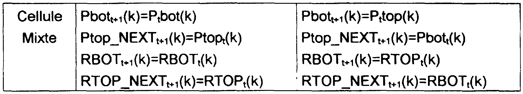
De manière similaire, les figures 12 et 13 représentent une cellule dans les cas respectifs où Ptop=Pbot=1 et Ptop est différent de Pbot, et sont appelées configurations Lambda et Mixte.

<tb><Tb>
<SEP> Tvpe <SEP> de <SEP> SWAP=O <SEP> SWAP <SEP> = <SEP> 1
<tb> <SEP> cellule
<tb> <SEP> Cellule <SEP> Pbott+1(k)=Ptbot(k) <SEP> Pbott+1(k)=Pttop(k)
<tb> <SEP> Lambda <SEP> Ptop~NEXTt+1(k)=Ptopt(k) <SEP> Ptop~NEXTt+1(k)=Pbott(k)
<tb> <SEP> RBOTt+1(k)=RBOTt(k)+RTOPt(k)* <SEP> RBOTt+1(k)=RTOP+(k)+RBOTt(k)* <SEP>
<tb> <SEP> ratio <SEP> ratio
<tb> <SEP> RTOP~NEXTt+1(k)=RTOPt(k) <SEP> RTOP~NEXTt+1(k)=RBOTt(k)
<tb> Cellule <SEP> Pbott+1(k)=Ptbot(k) <SEP> Pbott+1(k)=Pttop(k)
<tb> <SEP> Omega <SEP> Ptop~NEXTt+1(k)=Ptopt(k) <SEP> Ptop~NEXTt+1 <SEP> (k)=Pbott(k)
<tb> <SEP> RBOTt+1(k)=RBOTt(k) <SEP> RBOTt+1(k)=RTOPt(k) <SEP>
<tb> <SEP> RTOP~NEXTt+1(k)=RTOPt(k) <SEP> RTOP~NEXTt+1(k)=RBOTt(k) <SEP>
<tb> <SEP> +RBOTt( <SEP> k)*ratio <SEP> +RTOPt(k)tratio <SEP>
<tb>
<tb><SEP> cell
<tb><SEP> Cell <SEP> Pbott + 1 (k) = Ptbot (k) <SEP> Pbott + 1 (k) = Pttop (k)
<tb><SEP> Lambda <SEP> Ptop ~ NEXTt + 1 (k) = Ptopt (k) <SEP> Ptop ~ NEXTt + 1 (k) = Pbott (k)
<tb><SEP> RBOTt + 1 (k) = RBOTt (k) + RTOPt (k) * <SEP> RBOTt + 1 (k) = RTOP + (k) + RBOTt (k) * <SEP>
<tb><SEP> ratio <SEP> ratio
<tb><SEP> RTOP ~ NEXTt + 1 (k) = RTOPt (k) <SEP> RTOP ~ NEXTt + 1 (k) = RBOTt (k)
<tb> Cell <SEP> Pbott + 1 (k) = Ptbot (k) <SEP> Pbott + 1 (k) = Pttop (k)
<tb><SEP> Omega <SEP> Ptop ~ NEXTt + 1 (k) = Ptopt (k) <SEP> Ptop ~ NEXTt + 1 <SEP> (k) = Pbott (k)
<tb><SEP> RBOTt + 1 (k) = RBOTt (k) <SEP> RBOTt + 1 (k) = RTOPt (k) <SEP>
<tb><SEP> RTOP ~ NEXTt + 1 (k) = RTOPt (k) <SEP> RTOP ~ NEXTt + 1 (k) = RBOTt (k) <SEP>
<tb><SEP> + RBOTt (<SEP> k) * ratio <SEP> + RTOPt (k) tratio <SEP>
<Tb>
<tb> Cellule <SEP> Pbott+1(k)=Ptbot(k) <SEP> Pbott+1(k)=Pttop(k)
<tb> <SEP> Mixte <SEP> Ptop~NEXTt+1(k)=Ptopt(k) <SEP> Ptop~NEXTt+1(k)=Pbott(k)
<tb> <SEP> RBOTt+1(k)=RBOTt(k) <SEP> RBOTt+1(k)=RTOPt(k)
<tb> <SEP> RTOP~NEXTt+1(k)=RTOPt(k) <SEP> RTOP~NEXTt+1(k)=RBOTt(k)
<tb>
Tableau 2
Les parties Lambda réalisent la multiplication de l'équation (B), tandis que les parties Omega réalisent la division de l'équation (C).<tb> Cell <SEP> Pbott + 1 (k) = Ptbot (k) <SEP> Pbott + 1 (k) = Pttop (k)
<tb><SEP> Mixed <SEP> Ptop ~ NEXTt + 1 (k) = Ptopt (k) <SEP> Ptop ~ NEXTt + 1 (k) = Pbott (k)
<tb><SEP> RBOTt + 1 (k) = RBOTt (k) <SEP> RBOTt + 1 (k) = RTOPt (k)
<tb><SEP> RTOP ~ NEXTt + 1 (k) = RTOPt (k) <SEP> RTOP ~ NEXTt + 1 (k) = RBOTt (k)
<Tb>
Table 2
The Lambda parts perform the multiplication of the equation (B), while the Omega parts perform the division of the equation (C).
Si l'on prend comme exemple le polynôme S(z) tel que:
S(z)α14z5 - α10z4 + α z - α7z + α9z + α12
alors les conditions initiales sont:
#n-1(z) = 0 #0(z) = 1
#-1(z) = Z6
#0(z) = S(z)
Les tableaux 3 à 10 illustrent le contenu des cellules à la fin de chaque itération de l'algorithme.

S (z) α 14z5 - α 10z4 + α z - α 7z + α 9z + α 12
then the initial conditions are:
# n-1 (z) = 0 # 0 (z) = 1
# -1 (z) = Z6
# 0 (z) = S (z)
Tables 3 to 10 illustrate the contents of the cells at the end of each iteration of the algorithm.
<tb><Tb>
<SEP> Rang <SEP> 7 <SEP> 6 <SEP> 5 <SEP> 4 <SEP> 3 <SEP> 2 <SEP> 1 <SEP> 0 <SEP>
<tb> <SEP> RBOT <SEP> 1 <SEP> 0 <SEP> 0 <SEP> 0 <SEP> 0 <SEP> 0 <SEP> 0 <SEP> 11
<tb> <SEP> Pbot <SEP> 0 <SEP> 0 <SEP> 0 <SEP> 0 <SEP> 0 <SEP> 0 <SEP> 0 <SEP> 1
<tb> RTOP <SEP> α14 <SEP> <SEP> α10 <SEP> <SEP> α <SEP> <SEP> α7 <SEP> <SEP> α9 <SEP> <SEP> α-2 <SEP> <SEP> 0 <SEP> 0
<tb> <SEP> Ptop <SEP> 0 <SEP> 0 <SEP> '0 <SEP> '0 <SEP> 0 <SEP> :0 <SEP> 11 <SEP>
<tb>
Tableau 3 (Conditions initiales) (DegBot=6 - DegTop=5 - ratio=α14 - SWAP=1)

<tb><SEP> RBOT <SEP> 1 <SEP> 0 <SEP> 0 <SEP> 0 <SEP> 0 <SEP> 0 <SEP> 0 <SEP> 11
<tb><SEP> Pbot <SEP> 0 <SEP> 0 <SEP> 0 <SEP> 0 <SEP> 0 <SEP> 0 <SEP> 0 <SEP> 1
<tb> RTOP <SEP>α 14 <SEP><SEP>α 10 <SEP><SEP>α<SEP><SEP>α 7 <SEP><SEP>α 9 <SEP><SEP>α -2 <SEP><SEP> 0 <SEP> 0
<tb><SEP> Ptop <SEP> 0 <SEP> 0 <SEP>'0<SEP>' 0 <SEP> 0 <SEP>: 0 <SEP> 11 <SEP>
<Tb>
Table 3 (Initial conditions) (DegBot = 6 - DegTop = 5 - ratio = α 14 - SWAP = 1)
<tb> <SEP> Rang <SEP> 7 <SEP> 6 <SEP> 5 <SEP> 4 <SEP> 3 <SEP> 2 <SEP> 1 <SEP> 0
<tb> RBOT <SEP> α14 <SEP> α10 <SEP> α <SEP> α7 <SEP> <SEP> α9 <SEP> α12 <SEP> <SEP> 0 <SEP> 1
<tb> Pbot <SEP> 0 <SEP> 0 <SEP> 0 <SEP> 0 <SEP> 0 <SEP> 0 <SEP> 1 <SEP> 1
<tb> RTOP <SEP> |1 <SEP> 0 <SEP> :0 <SEP> 10 <SEP> o <SEP> 10 <SEP> 0 <SEP> 1
<tb> Ptop <SEP> 0 <SEP> 0 <SEP> 0 <SEP> 0 <SEP> 0 <SEP> 0 <SEP> 0 <SEP> 1
<tb>
Tableau 4 (Après SWAP) (DegBot=5 - DegTop=6 - ratio=a - SWAP=0)

<tb> RBOT <SEP>α 14 <SEP>α 10 <SEP>α<SEP>α 7 <SEP><SEP>α 9 <SEP>α 12 <SEP><SEP> 0 <SEP> 1
<tb> Pbot <SEP> 0 <SEP> 0 <SEP> 0 <SEP> 0 <SEP> 0 <SEP> 0 <SEP> 1 <SEP> 1
<tb> RTOP <SEP> | 1 <SEP> 0 <SEP>: 0 <SEP> 10 <SEP> o <SEP> 10 <SEP> 0 <SEP> 1
<tb> Ptop <SEP> 0 <SEP> 0 <SEP> 0 <SEP> 0 <SEP> 0 <SEP> 0 <SEP> 0 <SEP> 1
<Tb>
Table 4 (After SWAP) (DegBot = 5 - DegTop = 6 - ratio = a - SWAP = 0)
<tb> <SEP> Rang <SEP> 7 <SEP> 6 <SEP> 5 <SEP> 4 <SEP> 3 <SEP> 2 <SEP> 1 <SEP> 0
<tb> <SEP> RBOT <SEP> α14 <SEP> α10 <SEP> <SEP> α3 <SEP> <SEP> α- <SEP> <SEP> α9 <SEP> <SEP> α12 <SEP> <SEP> 0 <SEP> α
<tb> <SEP> Pbot <SEP> 0 <SEP> 0 <SEP> 0 <SEP> 0 <SEP> 0 <SEP> 0 <SEP> 1 <SEP> 1
<tb> RTOP <SEP> α11 <SEP> <SEP> α4 <SEP> <SEP> α8 <SEP> <SEP> α10 <SEP> <SEP> α13 <SEP> <SEP> 0 <SEP> 1 <SEP> 0
<tb> <SEP> Ptop <SEP> 0 <SEP> 0 <SEP> 0 <SEP> 0 <SEP> 0 <SEP> 0 <SEP> 1 <SEP> 1
<tb>
Tableau 5 (Itération 1) (DegBot=5 - DegTop=5 - ratio=α12 - SWAP=0)

<tb><SEP> RBOT <SEP>α 14 <SEP>α 10 <SEP><SEP>α 3 <SEP><SEP>α - <SEP><SEP>α 9 <SEP><SEP>α 12 <SEP><SEP> 0 <SEP>α
<tb><SEP> Pbot <SEP> 0 <SEP> 0 <SEP> 0 <SEP> 0 <SEP> 0 <SEP> 0 <SEP> 1 <SEP> 1
<tb> RTOP <SEP>α 11 <SEP><SEP>α 4 <SEP><SEP>α 8 <SEP><SEP>α 10 <SEP><SEP>α 13 <SEP><SEP> 0 <SEP> 1 <SEP> 0
<tb><SEP> Ptop <SEP> 0 <SEP> 0 <SEP> 0 <SEP> 0 <SEP> 0 <SEP> 0 <SEP> 1 <SEP> 1
<Tb>
Table 5 (Iteration 1) (DegBot = 5 - DegTop = 5 - ratio = α 12 - SWAP = 0)
<tb> Rang <SEP> 7 <SEP> 6 <SEP> 5 <SEP> 4 <SEP> 3 <SEP> 2 <SEP> 1 <SEP> 0
<tb> RBOT <SEP> α14 <SEP> <SEP> α10 <SEP> <SEP> α3 <SEP> α7 <SEP> <SEP> α9 <SEP> <SEP> α12 <SEP> <SEP> α12 <SEP> <SEP> α
<tb> Pbot <SEP> 0 <SEP> 0 <SEP> 0 <SEP> 0 <SEP> 0 <SEP> 0 <SEP> 1 <SEP> 1
<tb> RTOP <SEP> α <SEP> <SEP> α <SEP> <SEP> α <SEP> 1 <SEP> α9 <SEP> <SEP> 1 <SEP> 0 <SEP> 0
<tb> Ptop <SEP> 0 <SEP> 0 <SEP> 0 <SEP> 0 <SEP> 10 <SEP> 1 <SEP> 11 <SEP> 1 <SEP>
<tb>
Tableau 6 (Itération 2) (DegBot=5 - DegTop=4 - ratio=α - SWAP=1)

<tb> RBOT <SEP>α 14 <SEP><SEP>α 10 <SEP><SEP>α 3 <SEP>α 7 <SEP><SEP>α 9 <SEP><SEP>α 12 <SEP><SEP>α 12 <SEP><SEP>α
<tb> Pbot <SEP> 0 <SEP> 0 <SEP> 0 <SEP> 0 <SEP> 0 <SEP> 0 <SEP> 1 <SEP> 1
<tb> RTOP <SEP>α<SEP><SEP>α<SEP><SEP>α<SEP> 1 <SEP>α 9 <SEP><SEP> 1 <SEP> 0 <SEP> 0
<tb> Ptop <SEP> 0 <SEP> 0 <SEP> 0 <SEP> 0 <SEP> 10 <SEP> 1 <SEP> 11 <SEP> 1 <SEP>
<Tb>
Table 6 (Iteration 2) (DegBot = 5 - DegTop = 4 - ratio = α - SWAP = 1)
<tb> Rang <SEP> 7 <SEP> 6 <SEP> 5 <SEP> 4 <SEP> 3 <SEP> 2 <SEP> 1 <SEP> 0
<tb> RBOT <SEP> α <SEP> <SEP> α <SEP> <SEP> α <SEP> <SEP> 1 <SEP> α9 <SEP> <SEP> 1 <SEP> 0 <SEP> 0
<tb> Pbot <SEP> 0 <SEP> 0 <SEP> 0 <SEP> 0 <SEP> 0 <SEP> 1 <SEP> 1 <SEP> 1
<tb> <SEP> RTOP <SEP> α14 <SEP> <SEP> α10 <SEP> α <SEP> α7 <SEP> α9 <SEP> α12 <SEP> α12 <SEP> α
<tb> Ptop <SEP> O <SEP> 0 <SEP> 10 <SEP> 0 <SEP> 10 <SEP> 10 <SEP> 1 <SEP> 1
<tb>
Tableau 7 (Après SWAP) (DegBot=4 - DegTop=5 - ratio=α11 - SWAP=0)

<tb> RBOT <SEP>α<SEP><SEP>α<SEP><SEP>α<SEP><SEP> 1 <SEP>α 9 <SEP><SEP> 1 <SEP> 0 <SEP> 0
<tb> Pbot <SEP> 0 <SEP> 0 <SEP> 0 <SEP> 0 <SEP> 0 <SEP> 1 <SEP> 1 <SEP> 1
<tb><SEP> RTOP <SEP>α 14 <SEP><SEP>α 10 <SEP>α<SEP>α 7 <SEP>α 9 <SEP>α 12 <SEP>α 12 <SEP>α
<tb> Ptop <SEP> O <SEP> 0 <SEP> 10 <SEP> 0 <SEP> 10 <SEP> 10 <SEP> 1 <SEP> 1
<Tb>
Table 7 (After SWAP) (DegBot = 4 - DegTop = 5 - ratio = α 11 - SWAP = 0)
<tb> Rang <SEP> 7 <SEP> 6 <SEP> 5 <SEP> 4 <SEP> 3 <SEP> 2 <SEP> 1 <SEP> 0
<tb> RBOT <SEP> α <SEP> α <SEP> α <SEP> 1 <SEP> α9 <SEP> <SEP> 1 <SEP> α8 <SEP> α12
<tb> Pbot <SEP> 0 <SEP> 0 <SEP> 0 <SEP> 0 <SEP> 0 <SEP> 1 <SEP> 1 <SEP> 1
<tb> RTOP <SEP> α9 <SEP> <SEP> α8 <SEP> <SEP> α8 <SEP> <SEP> α6 <SEP> <SEP> α12 <SEP> <SEP> α12 <SEP> α <SEP> <SEP> 0
<tb> Ptop <SEP> 0 <SEP> 0 <SEP> 0 <SEP> 0 <SEP> 0 <SEP> 1 <SEP> 1 <SEP> 1
<tb>
Tableau 8 Itération 3) (DegBot=4 - DegTop=4 - ratio=α6 - SWAP=0)

<tb> RBOT <SEP>α<SEP>α<SEP>α<SEP> 1 <SEP>α 9 <SEP><SEP> 1 <SEP>α 8 <SEP>α 12
<tb> Pbot <SEP> 0 <SEP> 0 <SEP> 0 <SEP> 0 <SEP> 0 <SEP> 1 <SEP> 1 <SEP> 1
<tb> RTOP <SEP>α 9 <SEP><SEP>α 8 <SEP><SEP>α 8 <SEP><SEP>α 6 <SEP><SEP>α 12 <SEP><SEP>α 12 <SEP>α<SEP><SEP> 0
<tb> Ptop <SEP> 0 <SEP> 0 <SEP> 0 <SEP> 0 <SEP> 0 <SEP> 1 <SEP> 1 <SEP> 1
<Tb>
Table 8 Iteration 3) (DegBot = 4 - DegTop = 4 - ratio = α 6 - SWAP = 0)
<tb> <SEP> Rang <SEP> 7 <SEP> 6 <SEP> 5 <SEP> 4 <SEP> 3 <SEP> 2 <SEP> 1 <SEP> 0
<tb> <SEP> RBOT <SEP> α <SEP> <SEP> α <SEP> <SEP> α <SEP> <SEP> 1 <SEP> α9 <SEP> <SEP> α14 <SEP> <SEP> α11 <SEP> <SEP> α12
<tb> <SEP> Pbot <SEP> 0 <SEP> 0 <SEP> 0 <SEP> 0 <SEP> 0 <SEP> 1 <SEP> 1 <SEP> |1 <SEP>
<tb> <SEP> RTOP <SEP> 0 <SEP> 0 <SEP> 0 <SEP> α11 <SEP> <SEP> α12 <SEP> <SEP> α0 <SEP> 0
<tb> Ptop <SEP> 0 <SEP> 0 <SEP> 0 <SEP> 0 <SEP> 1 <SEP> 1 <SEP> 1 <SEP> 1
<tb>
Tableau 9 /Itération 4) (DegBot=4 - DegTop=3 - ratio=0 - SWAP=0)

<tb><SEP> RBOT <SEP>α<SEP><SEP>α<SEP><SEP>α<SEP><SEP> 1 <SEP>α 9 <SEP><SEP>α 14 <SEP><SEP>α 11 <SEP><SEP>α 12
<tb><SEP> Pbot <SEP> 0 <SEP> 0 <SEP> 0 <SEP> 0 <SEP> 0 <SEP> 1 <SEP> 1 <SEP> | 1 <SEP>
<tb><SEP> RTOP <SEP> 0 <SEP> 0 <SEP> 0 <SEP>α 11 <SEP><SEP>α 12 <SEP><SEP>α 0 <SEP> 0
<tb> Ptop <SEP> 0 <SEP> 0 <SEP> 0 <SEP> 0 <SEP> 1 <SEP> 1 <SEP> 1 <SEP> 1
<Tb>
Table 9 / Iteration 4) (DegBot = 4 - DegTop = 3 - ratio = 0 - SWAP = 0)
<tb> Rang <SEP> 7 <SEP> 6 <SEP> 5 <SEP> 4 <SEP> 3 <SEP> 2 <SEP> 1 <SEP> 0
<tb> <SEP> RBOT <SEP> α <SEP> α <SEP> α <SEP> 1 <SEP> α9 <SEP> α14 <SEP> α11 <SEP> <SEP> α12
<tb> Pbot <SEP> 0 <SEP> 0 <SEP> 0 <SEP> 0 <SEP> 0 <SEP> 1 <SEP> 1 <SEP> 1
<tb> RTOP <SEP> 0 <SEP> 0 <SEP> α11 <SEP> <SEP> α12 <SEP> <SEP> α <SEP> <SEP> 0 <SEP> 0 <SEP> 0
<tb> Ptop <SEP> 0 <SEP> 0 <SEP> 0 <SEP> 1 <SEP> 1 <SEP> 1 <SEP> 1 <SEP> 1
<tb>
Tableau 10 (Itération 5)
(DegBot=4 - DegTop=2 - ratio=0 - SWAP=0)
On obtient donc finalement:
#(z) = α12z + α11z +α14
#(z) = α11
Les coefficients de #(z) sont stockés dans la partie Lambda de
RBOT, tandis que les coefficients de #(z) sont stockés dans la partie Omega de RTOP.<tb> Rank <SEP> 7 <SEP> 6 <SEP> 5 <SEP> 4 <SEP> 3 <SEP> 2 <SEP> 1 <SEP> 0
<tb><SEP> RBOT <SEP>α<SEP>α<SEP>α<SEP> 1 <SEP>α 9 <SEP>α 14 <SEP>α 11 <SEP><SEP>α 12
<tb> Pbot <SEP> 0 <SEP> 0 <SEP> 0 <SEP> 0 <SEP> 0 <SEP> 1 <SEP> 1 <SEP> 1
<tb> RTOP <SEP> 0 <SEP> 0 <SEP>α 11 <SEP><SEP>α 12 <SEP><SEP>α<SEP><SEP> 0 <SEP> 0 <SEP> 0
<tb> Ptop <SEP> 0 <SEP> 0 <SEP> 0 <SEP> 1 <SEP> 1 <SEP> 1 <SEP> 1 <SEP> 1
<Tb>
Table 10 (Iteration 5)
(DegBot = 4 - DegTop = 2 - ratio = 0 - SWAP = 0)
So we finally get:
# (z) = α 12z + α 11z + α 14
# (z) = α 11
The coefficients of # (z) are stored in the Lambda part of
RBOT, while the coefficients of # (z) are stored in the Omega part of RTOP.
Après le calcul de A(z) et de Q(z), il faut ajuster les coefficients de Q(z) en rebouclant RTOP(r+1) sur RTOP(2) et en effectuant m=t+(degréE(z)/2) rotations. After calculating A (z) and Q (z), adjust the coefficients of Q (z) by looping RTOP (r + 1) over RTOP (2) and performing m = t + (degreeE (z) / 2) rotations.
Détermination de T(z) - syndrome modifié:
Avantageusement, le résolveur d'équations est également utilisé pour multiplier les polynômes E(z) et S(z) pour le calcul du syndrome modifié
T(z). Le résolveur d'équations dispose déjà des multiplieurs nécessaires. car la détermination du polynôme #(z) requiert une multiplication de polynômes. On met à profit ces ressources pour ce qui est de la multiplication E(z)*S(z), ce qui simplifie la constitution du générateur 2.Determination of T (z) - modified syndrome:
Advantageously, the resolver of equations is also used to multiply the polynomials E (z) and S (z) for the calculation of the modified syndrome
T (z). The equation solver already has the necessary multipliers. because the determination of the polynomial # (z) requires a multiplication of polynomials. These resources are used for the multiplication E (z) * S (z), which simplifies the constitution of the generator 2.
Le degré maximal de S(z) est 2t-1=r-1, tandis que celui de E(z) est 2t=r par construction (si le degré de E(z) est supérieur à 2t, le mot de code est marqué comme non corrigible). Le degré maximal de T(z) est donc r+1, ce qui correspond exactement au nombre de cellules du résolveur d'équations. The maximum degree of S (z) is 2t-1 = r-1, while that of E (z) is 2t = r by construction (if the degree of E (z) is greater than 2t, the codeword is marked as uncorrectable). The maximum degree of T (z) is therefore r + 1, which corresponds exactly to the number of cells of the solver of equations.
La figure 14 illustre la configuration d'une cellule pour la mise en oeuvre d'une multiplication. Les registres Ptop et Pbot servent à déterminer le contenu des registres RTOP(k) et RBOT(k). La configuration des cellules est assez proche de celle illustrée par le diagramme de la figure 12 (Ptop=Pbot=1), c'est à dire la configuration Lambda. Chaque registre RBOT reboucle sur son entrée à travers l'additionneur 108 associé, tandis que l'entrée de chaque registre RTOP est connecté à la sortie du registre RTOP de la cellule précédente. En dernier lieu, I'ensemble des multiplieurs des cellules sont connectés à une même entrée E, en vue de l'introduction des coefficients en série d'un des deux polynômes à multiplier. Dans le cadre du présent exemple, ce sont les coefficients de E(z) qui sont introduits par ce biais, mais on pourrait également introduire les coefficients de S(z). L'entrée E servait dans la configuration utilisée pour la détermination de A(z) et de #(z) pour foumir la valeur de 'ratio' à chaque cellule. Figure 14 illustrates the configuration of a cell for implementing multiplication. The Ptop and Pbot registers are used to determine the contents of the RTOP (k) and RBOT (k) registers. The configuration of the cells is quite similar to that illustrated by the diagram of Figure 12 (Ptop = Pbot = 1), ie the Lambda configuration. Each RBOT register loops back on its input through the associated adder 108, while the input of each RTOP register is connected to the output of the RTOP register of the preceding cell. Finally, all the multipliers of the cells are connected to the same input E, for the purpose of introducing the coefficients in series of one of the two polynomials to be multiplied. In the context of the present example, it is the coefficients of E (z) which are introduced by this means, but one could also introduce the coefficients of S (z). Input E was used in the configuration used for the determination of A (z) and # (z) to provide the value of 'ratio' to each cell.
Une autre différence avec la configuration Lambda de la figure 12 est que l'état du circuit inverseur 106 demeure identique tout au long de la multiplication. Another difference with the Lambda configuration of FIG. 12 is that the state of the inverter circuit 106 remains the same throughout the multiplication.
Le principe de fonctionnement est le suivant:
Dans un premier temps les coefficients de S(z) sont stockés dans les registres RTOP. Un 'O' est présenté à l'entrée du premier registre RTOP(0).The operating principle is as follows:
In a first step, the coefficients of S (z) are stored in the RTOP registers. An 'O' is presented at the input of the first RTOP (0) register.
Dans un second temps1 les coefficients E, de E(z) sont présentés par ordre d'indice croissant à l'entrée E, à raison d'un coefficient par cycle d'horloge. In a second step, the coefficients E, of E (z) are presented in order of increasing index at the input E, at the rate of one coefficient per clock cycle.
Le nombre de cycles d'horloge nécessaires pour effectuer la multiplication est égal au degré de E(z). The number of clock cycles required to perform the multiplication is equal to the degree of E (z).
A titre d'exemple, le tableau 1 1 donne le contenu de chacun des registres dans le cas d'une multiplication de S(z) et de E(z) où S(z) est de degré 3 et E(z) de degré 3

<tb> Cycle <SEP> Cellule <SEP> 4 <SEP> 3 <SEP> 2 <SEP> 1
<tb> d'Horloge
<tb> <SEP> Registre
<tb> RBOT <SEP> 0 <SEP> 0 <SEP> 0 <SEP> 0
<tb> <SEP> RTOP <SEP> S3 <SEP> 52 <SEP> Si <SEP> So
<tb> 1 <SEP> RBOT <SEP> S3E0 <SEP> S2E0 <SEP> S1E0 <SEP> S0E0
<tb> RTOP <SEP> S2 <SEP> S1 <SEP> S0 <SEP> 0
<tb> <SEP> 2 <SEP> IRBOT <SEP> IS3Eo+S2E1 <SEP> S2Eo+S1Er <SEP> S1E0+S0E1 <SEP> |S0E0 <SEP>
<tb> RTOP <SEP> S1 <SEP> S0 <SEP> 0 <SEP> 0
<tb> 3 <SEP> RBOT <SEP> S3E0+S2E1+S1E2 <SEP> S2E0+S1E1+S0E2 <SEP> S1E0+S0E1 <SEP> S0E0
<tb> <SEP> RTOP <SEP> S0 <SEP> 0 <SEP> 0 <SEP> 0
<tb> 4 <SEP> RBOT <SEP> S3E0+S2E1+S1E2+S0E3 <SEP> S2E0+S1E1+S0E2 <SEP> S1E0+S0E1 <SEP> S0E0
<tb> RTOP <SEP> 0 <SEP> 0 <SEP> o <SEP> o <SEP>
<tb>
Tableau 11
On voit que les registres RTOP(k) forment un registre à décalage servant uniquement à stocker les coefficients de S(z). Le registre à décalage est réalisé en choisissant correctement l'état des inverseurs 106. Les registres
RBOT(k) servent d'accumulateurs respectifs pour chaque coefficient du polynôme T(z).<tb> Cycle <SEP> Cell <SEP> 4 <SEP> 3 <SEP> 2 <SEP> 1
<tb> Clock
<tb><SEP> Registry
<tb> RBOT <SEP> 0 <SEP> 0 <SEP> 0 <SEP> 0
<tb><SEP> RTOP <SEP> S3 <SEP> 52 <SEP> If <SEP> So
<tb> 1 <SEP> RBOT <SEP> S3E0 <SEP> S2E0 <SEP> S1E0 <SEP> S0E0
<tb> RTOP <SEP> S2 <SEP> S1 <SEP> S0 <SEP> 0
<tb><SEP> 2 <SEP> IRBOT <SEP> IS3Eo + S2E1 <SEP> S2Eo + S1Er <SEP> S1E0 + S0E1 <SEP> | S0E0 <SEP>
<tb> RTOP <SEP> S1 <SEP> S0 <SEP> 0 <SEP> 0
<tb> 3 <SEP> RBOT <SEP> S3E0 + S2E1 + S1E2 <SEP> S2E0 + S1E1 + S0E2 <SEP> S1E0 + S0E1 <SEP> S0E0
<tb><SEP> RTOP <SEP> S0 <SEP> 0 <SEP> 0 <SEP> 0
<tb> 4 <SEP> RBOT <SEP> S3E0 + S2E1 + S1E2 + S0E3 <SEP> S2E0 + S1E1 + S0E2 <SEP> S1E0 + S0E1 <SEP> S0E0
<tb> RTOP <SEP> 0 <SEP> 0 <SEP> o <SEP> o <SEP>
<Tb>
Table 11
It can be seen that the RTOP registers (k) form a shift register only for storing the coefficients of S (z). The shift register is made by correctly choosing the state of the inverters 106. The registers
RBOT (k) serve as respective accumulators for each coefficient of the polynomial T (z).
Chaque registre RBOT(k) contient donc finalement le coefficient Tk,
![]()
![]()
Détermination du nouveau olvnôme de localisation d'erreur T(z)
Avantageusement, le résolveur d'équations est également utilisé pour multiplier les polynômes E(z) et A(z) pour te calcul de Y(z). Ce dernier polynôme est calculé une fois A(z) déterminé par le résolveur d'équations. Une fois que l'algorithme étendu d'Euclide a été mis en oeuvre, les coefficients de
A(z) sont stockés dans la partie Lambda de RBOT. Les autres registres
RTOP(k) et RBOT(k) sont mis à zéro.Determination of the new error locating error T (z)
Advantageously, the solver of equations is also used to multiply the polynomials E (z) and A (z) for the calculation of Y (z). This last polynomial is calculated once A (z) determined by the equation solver. Once the extended Euclidean algorithm has been implemented, the coefficients of
A (z) are stored in the Lambda part of RBOT. Other registries
RTOP (k) and RBOT (k) are set to zero.
La configuration des cellules pour réaliser la multiplication est illustrée par le diagramme de la figure 15. The configuration of the cells to carry out the multiplication is illustrated by the diagram of FIG.
Les registres RTOP < k) sont connectés en série à travers les additionneurs des cellules. La valeur '0' est présentée à l'entrée du premier registre RTOP(0). La sortie de chaque registre RBOT(k) est connectée au multiplieur de sa cellule k. Les valeurs stockées dans les registres RBOT(k) ne changent pas pendant la présente multiplication. Comme dans la configuration de la figure 14, les entrées des multiplieurs autres que celles connectées à la sortie des registres RBOT(k) sont interconnectées (référence E). RTOP registers <k) are connected in series through the cell adders. The value '0' is presented at the input of the first register RTOP (0). The output of each RBOT register (k) is connected to the multiplier of its cell k. The values stored in the RBOT registers (k) do not change during this multiplication. As in the configuration of FIG. 14, the inputs of the multipliers other than those connected to the output of the RBOT registers (k) are interconnected (reference E).
Le degré de A(z) est égal au nombre d'erreurs. Le degré de E(z) est égal au nombre d'effacements. The degree of A (z) is equal to the number of errors. The degree of E (z) is equal to the number of erasures.
Le tableau 12 donne le contenu des cellules après chaque cycle d'horloge.

<tb><Tb>
<SEP> Cellule <SEP> 7 <SEP> 6 <SEP> 5 <SEP> 4 <SEP> 3 <SEP> 2 <SEP> I <SEP> O
<tb> <SEP> Cycle
<tb> <SEP> Registre
<tb> <SEP> 1RBOT <SEP> 10 <SEP> O <SEP> I <SEP> <SEP> <SEP> <SEP> <SEP> AO <SEP> At <SEP> A2
<tb> 1 <SEP> RTOP <SEP> ,0~10 <SEP> 0 <SEP> O <SEP> O <SEP> O <SEP> <SEP> 10
<tb> IRBOT <SEP> 1 <SEP> O <SEP> |o <SEP> 0 <SEP> 0 <SEP> 1 <SEP> t <SEP> |AO <SEP> t <SEP> A2
<tb> ; <SEP> RTOP <SEP> O <SEP> O <SEP> <SEP> O <SEP> <SEP> A0E0 <SEP> 1A1E0 <SEP> 1A2E01O
<tb> <SEP> il <SEP> !RBOT <SEP> 0 <SEP> 0
<tb> <SEP> RTOP <SEP> 0 <SEP> 0 <SEP> 1 <SEP> <SEP> <SEP> AoEo <SEP> | <SEP> A1Eo+ <SEP> | <SEP> A2Eo+ <SEP> A2E1 <SEP> 0
<tb> <SEP> 0
<tb> <SEP> RTOP <SEP> O <SEP> 0
<tb> <SEP> '3 <SEP> RBOT <SEP> O <SEP> 1\2Eo+
<tb> <SEP> 0
<tb> <SEP> RTOP <SEP> O <SEP> 0
<tb> <SEP> hiEi+
<tb> <SEP> AoE2
<tb> <SEP> A0E1 <SEP> |AE1+ <SEP> |A1E2+ <SEP> |A1E3 <SEP> A1E
<tb> A0E2 <SEP> A0E2 <SEP> | <SEP> ACE3
<tb>
Tableau 12
Pendant le calcul de t(z), les multiplieurs restant actifs sont ceux des cellules pour lesquelles Pbot(k)=1. <SEP> Cell <SEP> 7 <SEP> 6 <SEP> 5 <SEP> 4 <SEP> 3 <SEP> 2 <SEP> I <SEP> O
<tb><SEP> Cycle
<tb><SEP> Registry
<tb><SEP> 1RBOT <SEP> 10 <SEP> O <SEP> I <SEP><SEP><SEP><SEP><SEP> AO <SEP> At <SEP> A2
<tb> 1 <SEP> RTOP <SEP>, 0 ~ 10 <SEP> 0 <SEP> O <SEP> O <SEP> O <SEP><SEP> 10
<tb> IRBOT <SEP> 1 <SEP> O <SEP> | o <SEP> 0 <SEP> 0 <SEP> 1 <SEP> t <SEP> | AO <SEP> t <SEP> A2
<tb>;<SEP> RTOP <SEP> O <SEP> O <SEP><SEP> O <SEP><SEP> A0E0 <SEP> 1A1E0 <SEP> 1A2E01O
<tb><SEP> it <SEP>! RBOT <SEP> 0 <SEP> 0
<tb><SEP> RTOP <SEP> 0 <SEP> 0 <SEP> 1 <SEP><SEP><SEP> AoEo <SEP>|<SEP> A1Eo + <SEP>|<SEP> A2Eo + <SEP> A2E1 <SEP> 0
<tb><SEP> 0
<tb><SEP> RTOP <SEP> O <SEP> 0
<tb><SEP>'3<SEP> RBOT <SEP> O <SEP> 1 \ 2Eo +
<tb><SEP> 0
<tb><SEP> RTOP <SEP> O <SEP> 0
<tb><SEP> hiEi +
<tb><SEP> AoE2
<tb><SEP> A0E1 <SEP> | AE1 + <SEP> | A1E2 + <SEP> | A1E3 <SEP> A1E
<tb> A0E2 <SEP> A0E2 <SEP> | <SEP> ACE3
<Tb>
Table 12
During the calculation of t (z), the remaining active multipliers are those of the cells for which Pbot (k) = 1.
Bien que le présent exemple de réalisation concerne la correction
Reed-Solomon, la configuration de deux mémoires décrite peut être appliquée dans tous les cas ou des paquets de données de longueur sensiblement différente doivent être corrigés.Although this exemplary embodiment relates to the correction
Reed-Solomon, the described two-memory configuration can be applied in any case where data packets of substantially different length need to be corrected.
En dernier lieu, la figure 16 représente un lecteur 200 de disque optique 201 comportent le dispositif conforme à l'invention. Ce lecteur comporte un bloc optique 202 comportant de manière connue un laser, des moyens de focalisation. des détecteurs photoélectriques. Le lecteur comporte également un moteur 203 commandé par une unité d'asservissement 204. Les données lues par le bloc optique sont transmises à un démultiplexeur 205. Les données de contrôle sont transmises à un microprocesseur 206 commandant un affichage 207 I'asservissement de la focalisation 208 et le suivi de piste 209. Un clavier 210 permet à l'utilisateur de commander le lecteur. Finally, FIG. 16 shows a reader 200 of optical disk 201 comprising the device according to the invention. This reader comprises an optical block 202 comprising, in a known manner, a laser, focusing means. photoelectric detectors. The reader also comprises a motor 203 controlled by a servo-control unit 204. The data read by the optical block are transmitted to a demultiplexer 205. The control data are transmitted to a microprocessor 206 controlling a display 207 the control of the focusing 208 and tracking 209. A keyboard 210 allows the user to control the reader.
Les paquets de données CD/DVD proprement dits sont transmis par le démultiplexeur 205 au dispositif de décodage 1 relié à la mémoire 5 et à une unité d'interpolation 211 qui fait office d'interface avec des convertisseurs numériquelanalogique non illustrés. The CD / DVD data packets themselves are transmitted by the demultiplexer 205 to the decoding device 1 connected to the memory 5 and to an interpolation unit 211 which interfaces with non-illustrated digital dialer converters.
Bien sur, si un autre algorithme que l'algorithme étendu d'Euclide est utilisé, et que cet algorithme nécessite aussi des multiplications de polynômes,
I'invention peut également s'appliquer. Of course, if another algorithm than Euclid's extended algorithm is used, and this algorithm also requires multiplications of polynomials,
The invention can also apply.
Claims (9)
Priority Applications (6)
| Application Number | Priority Date | Filing Date | Title |
|---|---|---|---|
| FR9803103A FR2776113A1 (en) | 1998-03-13 | 1998-03-13 | Reed-Solomon error correction in optical disc reader |
| DE69904164T DE69904164T2 (en) | 1998-03-13 | 1999-03-12 | DEVICE FOR CORRECTING ERRORS AND OPTICAL TURNTABLE INCLUDING SUCH A DEVICE |
| PCT/FR1999/000549 WO1999048216A1 (en) | 1998-03-13 | 1999-03-12 | Error correcting device and optical disk reader comprising same |
| ES99909003T ES2188138T3 (en) | 1998-03-13 | 1999-03-12 | ERROR CORRECTION DEVICE AND OPTICAL DISK READER THAT INCLUDES A DEVICE OF THIS TYPE. |
| US09/646,053 US6453441B1 (en) | 1998-03-13 | 1999-03-12 | Error correcting device and optical disk reader comprising same |
| EP99909003A EP1076933B1 (en) | 1998-03-13 | 1999-03-12 | Error correcting device and optical disk reader comprising same |
Applications Claiming Priority (1)
| Application Number | Priority Date | Filing Date | Title |
|---|---|---|---|
| FR9803103A FR2776113A1 (en) | 1998-03-13 | 1998-03-13 | Reed-Solomon error correction in optical disc reader |
Publications (1)
| Publication Number | Publication Date |
|---|---|
| FR2776113A1 true FR2776113A1 (en) | 1999-09-17 |
Family
ID=9524014
Family Applications (1)
| Application Number | Title | Priority Date | Filing Date |
|---|---|---|---|
| FR9803103A Pending FR2776113A1 (en) | 1998-03-13 | 1998-03-13 | Reed-Solomon error correction in optical disc reader |
Country Status (6)
| Country | Link |
|---|---|
| US (1) | US6453441B1 (en) |
| EP (1) | EP1076933B1 (en) |
| DE (1) | DE69904164T2 (en) |
| ES (1) | ES2188138T3 (en) |
| FR (1) | FR2776113A1 (en) |
| WO (1) | WO1999048216A1 (en) |
Cited By (1)
| Publication number | Priority date | Publication date | Assignee | Title |
|---|---|---|---|---|
| EP2194648A1 (en) * | 2008-12-03 | 2010-06-09 | Electronics and Telecommunications Research Institute | MPE-FEC RS decoder and decoding method thereof |
Families Citing this family (9)
| Publication number | Priority date | Publication date | Assignee | Title |
|---|---|---|---|---|
| US6662336B1 (en) * | 1999-07-06 | 2003-12-09 | Cirrus Logic, Inc. | Error correction method and apparatus |
| FR2817418B1 (en) * | 2000-11-27 | 2003-02-21 | Matra Nortel Communications | METHOD FOR DECODING A BLOCK OF SYMBOLS AND DEVICE IMPLEMENTING SUCH A METHOD |
| JP2003346432A (en) * | 2002-05-22 | 2003-12-05 | Internatl Business Mach Corp <Ibm> | Data storage device and data processing method |
| KR100698620B1 (en) | 2003-06-16 | 2007-03-21 | 삼성전자주식회사 | Digital transmitter/receiver system having a robust error correction coding/decoding apparatus and a method error correction coding/decoding therof |
| US7774688B1 (en) * | 2006-10-11 | 2010-08-10 | Marvell International Ltd. | Hardware efficient decoding system for Bose, Ray-Chaudhuri, Hocquenghem (BCH) product codes |
| TW200943741A (en) * | 2008-04-10 | 2009-10-16 | Univ Nat Chiao Tung | Decoding method and device suitable for shortened BCH codes or Reed-Solomon codes |
| JP2015053096A (en) | 2013-09-09 | 2015-03-19 | マイクロン テクノロジー, インク. | Semiconductor device and error correction method |
| US10381102B2 (en) | 2014-04-30 | 2019-08-13 | Micron Technology, Inc. | Memory devices having a read function of data stored in a plurality of reference cells |
| WO2017121473A1 (en) * | 2016-01-13 | 2017-07-20 | Huawei Technologies Duesseldorf Gmbh | Window-interleaved turbo (wi-turbo) codes |
Citations (5)
| Publication number | Priority date | Publication date | Assignee | Title |
|---|---|---|---|---|
| US4868828A (en) * | 1987-10-05 | 1989-09-19 | California Institute Of Technology | Architecture for time or transform domain decoding of reed-solomon codes |
| US5170399A (en) * | 1989-08-30 | 1992-12-08 | Idaho Research Foundation, Inc. | Reed-Solomon Euclid algorithm decoder having a process configurable Euclid stack |
| EP0620654A2 (en) * | 1993-03-31 | 1994-10-19 | Kabushiki Kaisha Toshiba | Decoder |
| US5642367A (en) * | 1994-02-07 | 1997-06-24 | Mitsubishi Semiconductor America, Inc. | Finite field polynomial processing module for error control coding |
| US5715262A (en) * | 1995-07-12 | 1998-02-03 | Lsi Logic Corporation | Errors and erasures correcting reed-solomon decoder |
Family Cites Families (1)
| Publication number | Priority date | Publication date | Assignee | Title |
|---|---|---|---|---|
| GB2318954B (en) * | 1996-10-29 | 2001-05-23 | Daewoo Electronics Co Ltd | Reed-solomon decoder for use in advanced television |
-
1998
- 1998-03-13 FR FR9803103A patent/FR2776113A1/en active Pending
-
1999
- 1999-03-12 EP EP99909003A patent/EP1076933B1/en not_active Expired - Lifetime
- 1999-03-12 US US09/646,053 patent/US6453441B1/en not_active Expired - Lifetime
- 1999-03-12 ES ES99909003T patent/ES2188138T3/en not_active Expired - Lifetime
- 1999-03-12 WO PCT/FR1999/000549 patent/WO1999048216A1/en active IP Right Grant
- 1999-03-12 DE DE69904164T patent/DE69904164T2/en not_active Expired - Lifetime
Patent Citations (5)
| Publication number | Priority date | Publication date | Assignee | Title |
|---|---|---|---|---|
| US4868828A (en) * | 1987-10-05 | 1989-09-19 | California Institute Of Technology | Architecture for time or transform domain decoding of reed-solomon codes |
| US5170399A (en) * | 1989-08-30 | 1992-12-08 | Idaho Research Foundation, Inc. | Reed-Solomon Euclid algorithm decoder having a process configurable Euclid stack |
| EP0620654A2 (en) * | 1993-03-31 | 1994-10-19 | Kabushiki Kaisha Toshiba | Decoder |
| US5642367A (en) * | 1994-02-07 | 1997-06-24 | Mitsubishi Semiconductor America, Inc. | Finite field polynomial processing module for error control coding |
| US5715262A (en) * | 1995-07-12 | 1998-02-03 | Lsi Logic Corporation | Errors and erasures correcting reed-solomon decoder |
Cited By (2)
| Publication number | Priority date | Publication date | Assignee | Title |
|---|---|---|---|---|
| EP2194648A1 (en) * | 2008-12-03 | 2010-06-09 | Electronics and Telecommunications Research Institute | MPE-FEC RS decoder and decoding method thereof |
| US8418041B2 (en) | 2008-12-03 | 2013-04-09 | Electronics And Telecommunications Research Institute | MPE-FEC RS decoder and decoding method thereof |
Also Published As
| Publication number | Publication date |
|---|---|
| DE69904164D1 (en) | 2003-01-09 |
| US6453441B1 (en) | 2002-09-17 |
| EP1076933A1 (en) | 2001-02-21 |
| DE69904164T2 (en) | 2003-07-17 |
| EP1076933B1 (en) | 2002-11-27 |
| WO1999048216A1 (en) | 1999-09-23 |
| ES2188138T3 (en) | 2003-06-16 |
Similar Documents
| Publication | Publication Date | Title |
|---|---|---|
| EP0108655B1 (en) | System for the detection and correction of transmission errors in a binary message using an error detecting and correcting interleaved reed-solomon cyclic code | |
| EP0265336B1 (en) | Galois field polynomial processing device and digital signal processor comprising such a device | |
| EP0821493B1 (en) | Error correction system in data frames comprising horizontal and vertical parity codes | |
| CH653457A5 (en) | METHOD FOR CORRECTING ERRORS IN DIGITAL DATA SIGNALS. | |
| FR2860360A1 (en) | Improved fidelity digital word communications system transmit/record having reed solomon coder/decoder and error correction block/memory registers | |
| FR2724273A1 (en) | SIGNAL PROCESSING CIRCUIT FOR IMPLEMENTING A VITERBI ALGORITHM | |
| FR2681177A1 (en) | System for storing digital data | |
| EP1076933B1 (en) | Error correcting device and optical disk reader comprising same | |
| FR2785743A1 (en) | DEVICE AND METHOD FOR ADAPTING TURBOCODERS AND DECODERS ASSOCIATED WITH VARIABLE LENGTH SEQUENCES | |
| EP0204635B1 (en) | Method for transmitting digital information in word blocks | |
| FR2540690A1 (en) | ENCODER CHECKER | |
| FR2776115A1 (en) | ERROR CORRECTION DEVICE AND OPTICAL DISK DRIVE HAVING SUCH A DEVICE | |
| FR2900294A1 (en) | Low density parity check decoder`s input/channel memory loading method for set top box, involves carrying out memory accesses in page mode for writing binary word streams in respective zones of input/channel memory by controlling module | |
| FR2673341A1 (en) | CIRCUIT ARRANGEMENT FOR DETECTING AND CORRECTING DEFECTS IN DATA WORDS. | |
| FR2845220A1 (en) | Method and device for decoding the algebraic-geometric codes at a point, comprises the construction of a sequence of syndromes matrices ending with a zero row elements matrix | |
| FR2713845A1 (en) | A method of interleaving and deinterleaving block and implementation device. | |
| FR2866998A1 (en) | Algebraic geometry code decoding method for encoded digital signal receiving apparatus, involves implementing errors correction algorithm adapted to Reed-Solomon code in order to calculate errors on components of Reed-Solomon code word | |
| EP0204612A1 (en) | Method for transmitting data with a possibility for packet error correction, and coding and decoding apparatus for carrying out said method | |
| FR2703551A1 (en) | Image data processing method and device for recording digital video to tape. | |
| EP0350368B1 (en) | Data coding and shaping device for a rotating-head recorder | |
| FR2768874A1 (en) | Reed Solomon decoder for transmission error correction | |
| FR2838580A1 (en) | Methods and devices of low cost for decoding the codes products | |
| FR2880218A1 (en) | DECODING METHOD FOR ALGEBRATIC GEOMETRY CODES AND DEVICE THEREOF | |
| EP0982866A1 (en) | Method for convolutional coding and transmission of a stream of packets of digital data, and a method and apparatus for corresponding decoding | |
| EP0165147A1 (en) | Coder and decoder for parameter block coding |