FR2759519A1 - DIGITAL SIGNAL TRANSMISSION METHOD, TRANSMITTER AND RECEIVER THEREFOR - Google Patents
DIGITAL SIGNAL TRANSMISSION METHOD, TRANSMITTER AND RECEIVER THEREFOR Download PDFInfo
- Publication number
- FR2759519A1 FR2759519A1 FR9701430A FR9701430A FR2759519A1 FR 2759519 A1 FR2759519 A1 FR 2759519A1 FR 9701430 A FR9701430 A FR 9701430A FR 9701430 A FR9701430 A FR 9701430A FR 2759519 A1 FR2759519 A1 FR 2759519A1
- Authority
- FR
- France
- Prior art keywords
- components
- transmitted
- symbol
- symbols
- frequencies
- Prior art date
- Legal status (The legal status is an assumption and is not a legal conclusion. Google has not performed a legal analysis and makes no representation as to the accuracy of the status listed.)
- Granted
Links
Classifications
-
- H—ELECTRICITY
- H04—ELECTRIC COMMUNICATION TECHNIQUE
- H04L—TRANSMISSION OF DIGITAL INFORMATION, e.g. TELEGRAPHIC COMMUNICATION
- H04L27/00—Modulated-carrier systems
- H04L27/26—Systems using multi-frequency codes
- H04L27/30—Systems using multi-frequency codes wherein each code element is represented by a combination of frequencies
Abstract
Description
Procédé de transmission de signaux numériques, émetteur et récepteur correspondants. Method of transmitting digital signals, corresponding transmitter and receiver
Le domaine de l'invention est celui de la transmission de signaux numériques. Plus précisément, la présente invention concerne un procédé de transmission de signaux numériques où la transmission de chaque bloc de signaux à transmettre à l'attention d'un récepteur consiste à transmettre à ce récepteur une ou plusieurs fréquences données, caractéristiques des données comprises dans ce bloc. The field of the invention is that of the transmission of digital signals. More specifically, the present invention relates to a method for transmitting digital signals in which the transmission of each block of signals to be transmitted to the attention of a receiver consists of transmitting to this receiver one or more given frequencies characteristic of the data included in this receiver. block.
L'invention concerne également un émetteur et un récepteur de tels signaux et trouve une application toute particulière à la transmission de signaux en modulation non cohérente dans des canaux présentant une forte dispersion. The invention also relates to a transmitter and a receiver of such signals and finds a very particular application to the transmission of non-coherent modulation signals in channels having a high dispersion.
Dans un systéme de transmission où une modulation en mode M-FSK (M
Ary Frequency Shift Keying) est utilisée, les données numériques à transmettre (bits) sont regroupées en blocs, chaque bloc comportant un nombre n de bits, avec
M = 2n La transmission de ces blocs consiste à affecter à chaque bloc une fréquence donnée choisie parmi M et à transmettre cette fréquence au récepteur.In a transmission system where modulation in M-FSK mode (M
Ary Frequency Shift Keying) is used, the digital data to be transmitted (bits) are grouped in blocks, each block comprising a number n of bits, with
M = 2n The transmission of these blocks consists in assigning to each block a given frequency chosen from M and transmitting this frequency to the receiver.
Par exemple, pour M = 8, chaque bloc comporte 3 bits et à chacun des blocs susceptibles d'être transmis correspond une et une seule fréquence de l'ensemble des M fréquences. On définit ainsi une relation univoque entre les blocs et les fréquences. La transmission s'effectue à une période symbolique Ts, aussi appelée temps symbole.For example, for M = 8, each block comprises 3 bits and each of the blocks that can be transmitted corresponds to one and only one frequency of all the M frequencies. This defines a unique relationship between blocks and frequencies. The transmission takes place at a symbolic period Ts, also called symbol time.
La figure 1 montre le spectre d'un signal BFSK (n = 1). L'amplitude est notée A et la fréquence f. Les fréquences centrales des signaux transmis sont notées fg et f1. Chaque canal présente une certaine largeur de bande due à la troncature temporelle réalisée pour la transmission de chacune des fréquences. La différence f1 -f0 est égale à liTs, c'est à dire que les fréquences fg et f1 sont orthogonales (absence de corrélation). Ceci assure que les canaux ne se chevauchent pas et qu'il n'existe pas d'interférence entre ces canaux (diaphonie). Figure 1 shows the spectrum of a BFSK signal (n = 1). The amplitude is denoted by A and the frequency f. The central frequencies of the transmitted signals are denoted fg and f1. Each channel has a certain bandwidth due to the time truncation performed for the transmission of each of the frequencies. The difference f1 -f0 is equal to liTs, that is to say that the frequencies fg and f1 are orthogonal (absence of correlation). This ensures that the channels do not overlap and that there is no interference between these channels (crosstalk).
De manière générale, cette orthogonalité est également respectée entre les M fréquences d'une modulation de type M-FSK.In general, this orthogonality is also respected between the M frequencies of an M-FSK type modulation.
L'inconvénient de cette solution connue est que l'efficacité spectrale (rapport entre le débit transmis et la largeur de bande totale occupée) est limitée. The disadvantage of this known solution is that the spectral efficiency (ratio of the transmitted bit rate to the total occupied bandwidth) is limited.
Plus précisément, le débit maximum pouvant être transmis est limité à une valeur donnée en fonction de la largeur de bande totale allouée. Une augmentation de débit se traduit par une limitation de Ts et donc nécessairement par un espacement plus important entre les fréquences fg et f1. More specifically, the maximum rate that can be transmitted is limited to a given value depending on the total allocated bandwidth. An increase in the flow rate results in a limitation of Ts and therefore necessarily in a greater spacing between the frequencies fg and f1.
La présente invention a notamment pour objectif de pallier cet inconvénient. The present invention particularly aims to overcome this disadvantage.
Plus précisément, un des objectifs de l'invention est de fournir un procédé de transmission de signaux numériques présentant une efficacité spectrale améliorée par rapport à l'état de la technique précité. More specifically, one of the objectives of the invention is to provide a method for transmitting digital signals having an improved spectral efficiency compared to the state of the art mentioned above.
Un autre objectif de l'invention est de fournir un émetteur et un récepteur de signaux numériques mettant en oeuvre ce procédé. Another object of the invention is to provide a transmitter and a digital signal receiver implementing this method.
Ces objectifs, ainsi que d'autres qui apparaîtront par la suite, sont atteints grâce à un procédé de transmission d'un signal numérique se présentant sous forme de blocs, chacun des blocs comprenant au moins un bit et correspondant à un symbole à transmettre, la transmission de chacun des symboles consistant à transmettre au moins une fréquence constituant une composante correspondant de manière univoque à ce bloc, les composantes de symboles différents étant corrélées entre elles. These objectives, as well as others that will appear later, are achieved by a method of transmitting a digital signal in the form of blocks, each of the blocks comprising at least one bit and corresponding to a symbol to be transmitted, transmitting each of the symbols of transmitting at least one frequency constituting a component uniquely corresponding to that block, the different symbol components being correlated with each other.
II existe donc une corrélation non nulle entre les composantes des symboles transmis. Le fait de rapprocher les fréquences possibles permet d'augmenter de maniére importante l'efficacité spectrale. There is therefore a non-zero correlation between the components of the transmitted symbols. Bringing together the possible frequencies makes it possible to significantly increase the spectral efficiency.
Préférentiellement, le procédé consiste à transmettre, pour chacun des symboles, un nombre N de composantes, les composantes de symboles différents étant corrélées entre elles. Preferably, the method consists in transmitting, for each of the symbols, a number N of components, the components of different symbols being correlated with each other.
Ces composantes peuvent être transmises par répartition temporelle et/ou diversité fréquentielle. These components can be transmitted by time division and / or frequency diversity.
L'invention concerne également un émetteur d'un signal numérique se présentant sous forme de blocs, chacun des blocs comprenant au moins un bit et correspondant à un symbole à transmettre, L'émetteur comprenant des moyens affectant de manière univoque à chacun des symboles au moins une fréquence constituant une composante du symbole, les composantes affectées à des symboles différents étant corrélées entre elles. The invention also relates to a transmitter of a digital signal in the form of blocks, each of the blocks comprising at least one bit and corresponding to a symbol to be transmitted, the transmitter comprising means uniquely affecting each of the symbols. least one frequency constituting a component of the symbol, the components assigned to different symbols being correlated with each other.
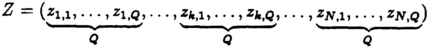
L'invention concerne également un récepteur d'un signal numérique transmis par un tel émetteur, caractérisé en ce qu'il comporte un jeu de filtres adaptés centrés chacun sur l'une des composantes, les échantillons des signaux de sortie de ces filtres constituant les composantes d'un vecteur Z donné par:

avec Q le nombre de valeurs différentes des composantes, le récepteur comprenant des moyens de calcul maximisant la variable de décision suivante

en se basant, dans le calcul de la variable de vraisemblance relative à un symbole donné, sur les seules sorties des filtres adaptés centrés sur les fréquences où une des composantes serait émise.The invention also relates to a receiver of a digital signal transmitted by such a transmitter, characterized in that it comprises a set of adapted filters each centered on one of the components, the samples of the output signals of these filters constituting the components of a vector Z given by:
with Q the number of different values of the components, the receiver comprising calculation means maximizing the following decision variable
based, in the calculation of the likelihood variable relative to a given symbol, on the only outputs of the adapted filters centered on the frequencies where one of the components would be emitted.
D'autres caractéristiques et avantages de l'invention apparaîtront à la lecture de la description suivante d'un mode de réalisation préférentiel, donné à titre illustratif et non limitatif, et des dessins annexés dans lesquels - la figure 1 montre le spectre d'un signal BFSK de l'art connu - la figure 2 montre la répartition temps-fréquence des fréquences transmises
dans l'invention, L'exemple étant pris pour Q = 8 - la figure 3 montre la probabilité d'erreur par paire sur le canal de Rayleigh de
signaux à composantes corrélées en fonction du rapport signal à bruit, pour
N=4; - la figure 4 montre la probabilité d'erreur sur le canal de Rayleigh de signaux à
composantes corrélées en fonction du rapport signal à bruit, pour N = 4 - la figure 5 montre la probabilité d'erreur sur le canal de Rayleigh de signaux à
composantes corrélées en fonction du rapport signal à bruit, pour N = 8 - la figure 6 est un schéma synoptique d'un exemple d'un émetteur de signaux
numériques mettant en oeuvre le procédé selon l'invention, - la figure 7 est un schéma synoptique d'un exemple de récepteur des signaux
numériques transmis par l'émetteur de la figure 6.Other features and advantages of the invention will appear on reading the following description of a preferred embodiment, given by way of illustration and not limitation, and the accompanying drawings in which - Figure 1 shows the spectrum of a BFSK signal of the known art - Figure 2 shows the time-frequency distribution of the transmitted frequencies
in the invention, the example being taken for Q = 8 - Figure 3 shows the probability of pair error on the Rayleigh channel of
component signals correlated with the signal-to-noise ratio, for
N = 4; FIG. 4 shows the probability of error on the Rayleigh channel of signals to
components correlated according to the signal-to-noise ratio, for N = 4 - Figure 5 shows the probability of error on the Rayleigh channel of signals to
components correlated according to the signal-to-noise ratio, for N = 8 - Figure 6 is a block diagram of an example of a signal transmitter
numerals implementing the method according to the invention, - Figure 7 is a block diagram of an example of a signal receiver
numbers transmitted by the transmitter of Figure 6.
La figure 1 a été décrite précédemment en référence à l'état de la technique. Figure 1 has been described above with reference to the state of the art.
La présente invention est basée sur le fait que les Q fréquences pouvant être transmises par composante présentent entre elles une corrélation, c'est à dire que l'espacement entre ces fréquences est inférieur à 1/Ts. II existe donc une corrélation non nulle entre les composantes des symboles transmis. Le fait de rapprocher les fréquences transmises permet d'augmenter de manière importante l'efficacité spectrale. The present invention is based on the fact that the Q frequencies that can be transmitted by component have a correlation between them, that is to say that the spacing between these frequencies is less than 1 / Ts. There is therefore a non-zero correlation between the components of the transmitted symbols. The fact of bringing the transmitted frequencies together makes it possible to significantly increase the spectral efficiency.
La figure 2 montre la répartition temps-fréquence des fréquences transmises dans l'invention, L'exemple étant pris pour Q = 8. L'axe temporel t est subdivisé en cases temps élémentaires de durée Ts et l'axe fréquentiel f en 8 voies espacées deux à deux de 1/4Ts. Ces fréquences sont donc espacées de bien moins que la distance 1/Ts garantissant l'orthogonalité. La bande totale occupée est égale à W = 2ils, identique à celle d'une modulation BFSK classique (Fig.1). FIG. 2 shows the time-frequency distribution of the frequencies transmitted in the invention, the example being taken for Q = 8. The time axis t is subdivided into elementary time boxes of duration Ts and the frequency axis f into 8 channels. spaced two by two from 1 / 4Ts. These frequencies are therefore spaced far less than the distance 1 / Ts guaranteeing the orthogonality. The total band occupied is equal to W = 2ils, identical to that of a conventional BFSK modulation (FIG.
On considérera dans un premier temps des signaux à une seule dimension, c'est à dire que la transmission d'un symbole n'occupe qu'une case temporelle Ts. We will first consider single-dimensional signals, ie the transmission of a symbol occupies only one time slot Ts.
Dans une case donnée, à chaque temps symbole Ts, une seule fréquence est émise.In a given box, at each symbol time Ts, a single frequency is transmitted.
Le fait de prévoir plus de deux fréquences dans la largeur de bande W augmente l'efficacité spectrale élémentaire du plan temps-fréquence ainsi découpé. On constate qu'on a la possibilité d'émettre 8 symboles différents en associant un symbole à une fréquence. Le nombre de bits par symbole est de 3. Il en résulte une efficacité spectrale de 1,5 bitis/Hz. En comparant cet exemple au cas d'une BFSK qui utilise deux fréquences seulement dans la même bande élémentaire W, on constate que le gain en efficacité spectrale est d'un facteur 3. Autrement dit, 3 fois plus de bits peuvent être transmis dans la même bande fréquentielle.Providing more than two frequencies in the bandwidth W increases the elemental spectral efficiency of the time-frequency plane thus cut. It can be seen that it is possible to transmit 8 different symbols by associating a symbol with a frequency. The number of bits per symbol is 3. This results in a spectral efficiency of 1.5 bitis / Hz. Comparing this example to the case of a BFSK which uses only two frequencies in the same elementary band W, it is found that the gain in spectral efficiency is of a factor 3. In other words, 3 times more bits can be transmitted in the same frequency band.
L'accroissement de l'efficacité spectrale s'accompagne d'une dégradation des performances minime due à la corrélation non nulle entre les différentes fréquences dans une case élémentaire. Cependant, cette dégradation est compensée lorsque des alphabets à haute efficacité spectrale sont utilisés (signaux multidimensionnels), comme il est décrit ci-dessous. The increase in spectral efficiency is accompanied by a minimal degradation of performance due to the nonzero correlation between the different frequencies in an elementary box. However, this degradation is compensated for when high spectral efficiency alphabets are used (multidimensional signals), as described below.
Les signaux que nous considérons dans la suite utiliseront toujours une fréquence et une seule à la fois par case temps-fréquence. Les symboles émis ont tous la même énergie. Un symbole constitué de N composantes a donc la structure suivante
![]()
![]()
Le récepteur qui sera décrit par la suite dispose d'un filtre adapté pour chacune des fréquences possibles. Les sorties des détecteurs d'énergie de ce récepteur constituent le vecteur Z avec

En supposant qu'il n'existe aucune corrélation entre les composantes dans les cases temps-fréquence adjacentes (canal de transmission sans mémoire), la densité de probabilité conjointe des composantes du vecteur Z s'écrit (relation 1)

Le récepteur optimal selon le critère du maximum à posteriori est celui qui choisit le symbole Sj maximisant cette densité de probabilité conjointe. On montre facilement que la maximisation de l'expression de la relation 1 revient à maximiser l'expression

En d'autres termes il suffit de se baser, dans le calcul de la variable de vraisemblance relative à un symbole Sj donné, sur les seules sorties des filtres adaptés branchés sur les fréquences où un état logique 1 serait émis. A partir de ce point, on peut montrer que le récepteur optimal a pour fonction de maximiser le produit scalaire (Z, Sj}. Cette maximisation consiste à calculer les variables de décision Aj données par:

Afin de quantifier le gain apporté par l'invention, il est pertinent d'effectuer un calcul de probabilité d'erreur par paire dans l'hypothèse de l'émission d'un symbole S1. In order to quantify the gain provided by the invention, it is relevant to perform a pairwise error probability calculation in the event of the emission of a symbol S1.
La probabilité d'une mauvaise détection consiste à décider que le symbole reçu est S2 # S1. Cette probabilité n'est autre que la probabilité P(A1 < A2), ou aussi (relation 2):

Dans l'expression précédente l'indice ik est omis et les indices '1' ou '2' font référence aux symboles S1 et S2 respectivement. In the preceding expression the index ik is omitted and the indices '1' or '2' refer to the symbols S1 and S2 respectively.
En transformant l'expression précédente en une probabilité d'une forme hermitienne quadratique, on peut définir le vecteur p comme suit
P = (T1,1, T2,1, T1,2, T2,2,...,T1,N, T2,N)
L'expression de la relation 2 implique donc
P(S1 S2) = P(f = ptFpg < O) où f = ptFp* est la forme hermitienne recherchée avec

P = (T1,1, T2,1, T1,2, T2,2, ..., T1, N, T2, N)
The expression of relation 2 therefore implies
P (S1 S2) = P (f = ptFpg <O) where f = ptFp * is the hermitian form sought with
On sait que la fonction caractéristique d'une telle forme hermitienne est (relation 3):
= det(I - 1j2R*F) où R = 1E[#t#*] désigne la matrice de corrélation du vecteur p. We know that the characteristic function of such a hermitian form is (relation 3):
= det (I - 1j2R * F) where R = 1E [# t # *] denotes the correlation matrix of the vector p.
2
Les variables rk ne sont autres que les échantillons aux sorties des filtres adaptés. Le symbole S1 étant émis, ces variables sont données par
Tl,k = hk + bl,k
r2,k = pkhk + b2,k où k désigne la corrélation existante entre les deux composantes d'ordre k des deux symboles. Si on utilise des filtres rectangulaires de durée Ts, cette corrélation s'exprime comme (relation 4):

avec Afr = fî ,k - f2,k la différence entre les fréquences des deux composantes et = = ,k - é2,k un déphasage tenant compte de l'incohérence des oscillateurs utilisés pour chaque fréquence au récepteur. Nous supposons dans la suite que les corrélations sont toutes différentes.2
The variables rk are none other than the samples at the outputs of the adapted filters. With the symbol S1 being issued, these variables are given by
Tl, k = hk + bl, k
r2, k = pkhk + b2, where k denotes the correlation existing between the two components of order k of the two symbols. If we use rectangular filters of duration Ts, this correlation is expressed as (relation 4):
with Afr = f1, k - f2, k the difference between the frequencies of the two components and = =, k - é2, k a phase shift taking into account the inconsistency of the oscillators used for each frequency at the receiver. We assume in the following that the correlations are all different.
Les variables aléatoires r1 k suivent des lois Gaussiennes centrées de variances (relation 5):

De leur côté, les variables aléatoires r2,k suivent aussi des lois Gaussiennes centrées mais de variances (relation 6):

D'autre part, il est important de noter que les échantillons de bruit bl,k et b2,k sont aussi corrélés. On a en effet (relation 7):
![]()
II résulte de ce qui précède que r1,k et r2,k sont corrélés tel que (relation 8):
![]()
![]()
It follows from the above that r1, k and r2, k are correlated such that (relation 8):
![]()
En remarquant que les variables aléatoires relatives à deux composantes distinctes ont des corrélations nulles, les expressions des relations 5 à 8 permettent d'écrire la matrice de corrélation du vecteur p comme
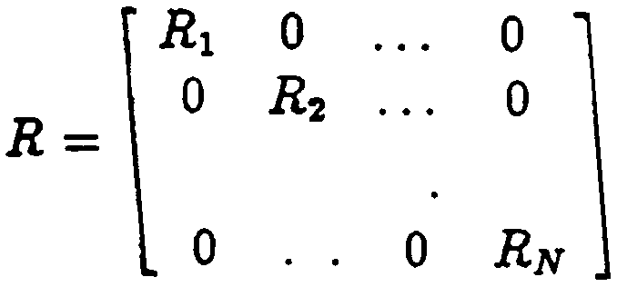
où Rk est une matrice 2 x 2 donnée par
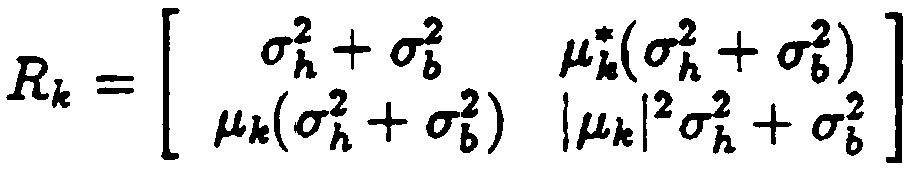
where Rk is a 2 x 2 matrix given by
Dans ces conditions l'expression de la fonction caractéristique de la relation 3 deviens

Un calcul direct de det(l - j2sRkFk) donne
det(I - j2#Rk*Fk) = (1 - j2#uk)(1 + j2(tk) avec:

det (I - j2 # Rk * Fk) = (1 - j2 # uk) (1 + j2 (tk) with:
Dans les expressions précédentes nous avons défini

le rapport signal sur bruit par symbole. In previous expressions we defined
the signal to noise ratio per symbol.
La fonction caractéristique de f s'écrit donc maintenant

En procédant à une décomposition en éléments simples de kJlf(j4), on obtient
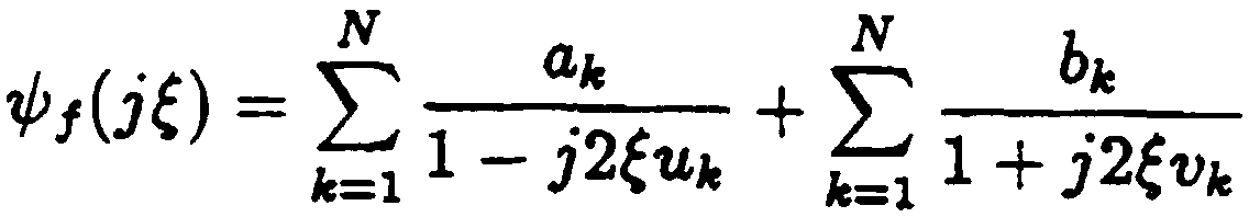
en considérant que ui j pour i W j.By performing a decomposition into simple elements of kJlf (j4), we obtain
considering that ui j for i W j.
La probabilité d'erreur est donc égale ou encore


où r est défini par:
F
γ + 2N
Une expression plus simple de cette probabilité d'erreur, ainsi qu'une expression asymptotique pour les grands rapports signal sur bruit, sont les suivantes

et (relation 9):

where r is defined by:
F
γ + 2N
A simpler expression of this probability of error, as well as an asymptotic expression for large signal-to-noise ratios, are as follows
and (relation 9):
L'expression asymptotique de la probabilité d'erreur par paire montre que si
| k| est égal à | | quelque soit k, la dégradation du rapport signal sur bruit par symbole y sera la même quelle que soit la dimension N des symboles.The asymptotic expression of the pair error probability shows that if
| k | is equal to | | whatever k, the degradation of the signal-to-noise ratio per symbol y will be the same whatever the dimension N of the symbols.
Pour le cas particulier N = 1, on aboutit à l'expression de la probabilité d'erreur de deux symboles binaires corrélés sur canal de Rayleigh donnée par

D'autre part, si toutes les corrélations entre les composantes sont identiques ( k = V k), on sait calculer la probabilité d'erreur par paire égale à (relation 10):
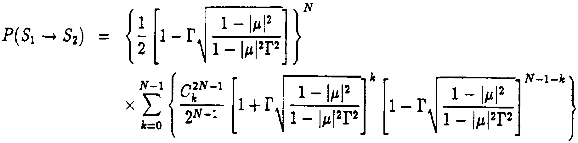
La figure 3 montre la probabilité d'erreur par paire P(S1 - > S2) sur le canal de
Rayleigh de signaux à composantes corrélées en fonction du rapport signal à bruit y exprimé en dB, pour une dimension N = 4.FIG. 3 shows the probability of error per pair P (S1 -> S2) on the channel of
Rayleigh of component signals correlated as a function of the signal-to-noise ratio y expressed in dB, for a dimension N = 4.
Les valeurs choisies de la corrélation I p | 2 = 0, I 2 = 0,09, 1 p | 2 = 0,4 et 1 p 1 2 = 0,8 correspondent respectivement à des fréquences espacées de 1/Ts (état de la technique, référence 30), 1/4Ts (référence 31), 1/2Ts (référence 32), et 3/4Ts (référence 33). La dégradation asymptotique des performances est bien en accord avec l'expression de la relation 8 qui prévoit une diminution du rapport signal sur bruit d'un facteur 1 - I p | 2
Le gain en efficacité spectrale obtenu à l'aide de signaux à composantes corrélées peut être illustré par l'exemple suivant
En considérant d'abord un alphabet à deux signaux (BFSK) avec une diversité d'ordre N = 4, les deux symboles de cet alphabet sont
s1 = (1, 0, 1, 0, 1, 0, 1, 0)
S2= (0,1, 0,1, 0,1, 0,1)
Les performances de cet alphabet à deux symboles sont obtenues en utilisant la relation 10 avec N = 4 et u = 0. L'efficacité spectrale est de 1/8 bit/s/Hz (le facteur d'expansion spectrale par rapport à 1 bit/s/Hz est Be = 8). Ceci correspond à l'état de la technique.The chosen values of the correlation I p | 2 = 0, I 2 = 0.09, 1 p | 2 = 0.4 and 1 p 1 2 = 0.8 respectively correspond to frequencies spaced apart from 1 / Ts (state of the art, reference 30), 1 / 4Ts (reference 31), 1 / 2Ts (reference 32), and 3 / 4Ts (reference 33). The asymptotic degradation of the performances is in agreement with the expression of the relation 8, which provides for a reduction of the signal-to-noise ratio by a factor 1 - I p | 2
The gain in spectral efficiency obtained using correlated component signals can be illustrated by the following example
Considering first a two-signal alphabet (BFSK) with a diversity of order N = 4, the two symbols of this alphabet are
s1 = (1, 0, 1, 0, 1, 0, 1, 0)
S2 = (0.1, 0.1, 0.1, 0.1)
The performances of this two-symbol alphabet are obtained by using the relation 10 with N = 4 and u = 0. The spectral efficiency is 1/8 bit / s / Hz (the spectral expansion factor with respect to 1 bit / s / Hz is Be = 8). This corresponds to the state of the art.
L'invention propose pour sa part d'employer également une diversité d'ordre
N = 4 avec des signaux à composantes corrélées, pour Q = 8. En numérotant les fréquences disponibles dans une case temps-fréquence de 1 à 8, les M = 8 symboles possibles sont donnés ci-après par leurs numéros de fréquences utilisées dans les différentes composantes.

N = 4 with correlated component signals, for Q = 8. By numbering the available frequencies in a time-frequency box from 1 to 8, the M = 8 possible symbols are given below by their frequency numbers used in the different components.
A titre d'exemple, L'émission du symbole S1 consiste à transmettre les fréquences 1, 2, 1 et 2 successivement (répartition temporelle) ou simultanément (répartition fréquentielle dans la bande totale K*W). Une combinaison d'une transmission temporelle et fréquentielle est également envisageable. By way of example, the transmission of the symbol S1 consists in transmitting the frequencies 1, 2, 1 and 2 successively (time distribution) or simultaneously (frequency distribution in the total band K * W). A combination of time and frequency transmission is also possible.
La bande totale K*W nécessaire pour l'émission d'un symbole reste identique à celle de la BFSK (NQ/4Ts = 8/Ts) mais on dispose maintenant dans cette bande de
M = 8 symboles et l'efficacité spectrale passe à 3/8 bit/s/Hz (Be = 2,66).The total band K * W necessary for the emission of a symbol remains identical to that of the BFSK (NQ / 4Ts = 8 / Ts) but we now have in this band of
M = 8 symbols and the spectral efficiency goes to 3/8 bit / s / Hz (Be = 2.66).
A titre de comparaison, une modulation BFSK classique occupe une largeur de bande de 2/Ts. Lorsque les composantes transmises ne sont plus espacées que de
Ts/4, le gain en bande est d'un facteur 3 pour la transmission d'un même débit. II est des lors possible, en occupant la même bande que celle de la BFSK classique, de prévoir au total 4 sous-bandes pour la transmission des composantes. La transmission peut dès lors s'opérer en diversité fréquentielle.By way of comparison, conventional BFSK modulation occupies a bandwidth of 2 / Ts. When the transmitted components are no longer spaced apart
Ts / 4, the band gain is a factor of 3 for the transmission of the same bit rate. It is therefore possible, by occupying the same band as that of the conventional BFSK, to provide a total of 4 sub-bands for the transmission of the components. The transmission can therefore operate in frequency diversity.
On constate que tout couple de symboles a les quatre fréquences toutes différentes. On obtient ainsi la diversité d'ordre 4. D'autre part, en examinant les 8 symboles proposés on déduit que les symboles les plus corrélés (S4 et S7 par exemple) ont deux composantes pour lesquelles les fréquences sont adjacentes (à 1/4Ts), une troisième composante avec des fréquences espacées de 1/2Ts et une dernière avec un espacement de 3/4 Ts. Les corrélations qui en résultent sont I p1 1 2 = 2 12 = 0,8, | p3 | 2 = 0,4 et | 4 | 2 = 0,09 (on suppose que les filtres utilisés sont rectangulaires, et donc que les corrélations sont données par la relation 4). It can be seen that any pair of symbols has all four different frequencies. Thus, the diversity of order 4 is obtained. On the other hand, by examining the 8 proposed symbols we deduce that the most correlated symbols (S4 and S7 for example) have two components for which the frequencies are adjacent (at 1 / 4Ts ), a third component with frequencies spaced by 1 / 2Ts and a last one with a spacing of 3/4 Ts. The resulting correlations are I p1 1 2 = 2 12 = 0.8, | p3 | 2 = 0.4 and | 4 | 2 = 0.09 (it is assumed that the filters used are rectangular, and therefore that the correlations are given by the relation 4).
Les performances du système à composantes corrélées sont majorées par la borne de l'union. Elle indique que la probabilité d'erreur symbole est inférieure à M-1 fois la probabilité d'erreur par paire la plus grande. En d'autres termes Pe < (M-1) P(S4 o S7)
D'autre part, une borne inférieure est obtenue en notant que la probabilité d'erreur est supérieure à la probabilité d'erreur par paire des deux symboles les plus éloignés (c'est à dire les moins corrélés) mais qui sont les plus proches voisins l'un de l'autre. Les deux symboles S1 et S2 remplissent cette condition. Ainsi on a
Pe > P(S1 o S2)
Les différentes probabilités d'erreur par paire sont obtenues à l'aide de la relation P(S1 o S2) précédemment donnée. Enfin, la probabilité d'erreur binaire est approximée par Pb = Pe /2.The performance of the correlated component system is increased by the terminal of the union. It indicates that the symbol error probability is less than M-1 times the highest pair error probability. In other words Pe <(M-1) P (S4 or S7)
On the other hand, a lower bound is obtained by noting that the probability of error is greater than the probability of pairwise error of the two most distant symbols (ie the least correlated) but which are the closest neighbors of each other. The two symbols S1 and S2 fulfill this condition. So we have
Pe> P (S1 o S2)
The different error probabilities per pair are obtained using the previously given relation P (S1 o S2). Finally, the probability of a binary error is approximated by Pb = Pe / 2.
Les performances des deux systèmes sont comparées dans la figure 4 qui montre la probabilité d'erreur sur le canal de Rayleigh de signaux à composantes corrélées en fonction du rapport signal à bruit exprimé en dB, pour N = 4. La caractéristique en trait plein correspond à celle d'un système BFSK classique (n = 1) pour Be = 8 et celles en traits discontinus aux bornes inférieures et supérieures évoquées ci-dessus. The performance of the two systems is compared in Figure 4 which shows the probability of error on the Rayleigh channel of component-correlated signals as a function of the signal-to-noise ratio expressed in dB, for N = 4. to that of a classical BFSK system (n = 1) for Be = 8 and those in broken lines at the lower and upper bounds mentioned above.
On constate la très bonne performance des signaux corrélés dont la localisation des bornes inférieure et supérieure montre des performances exactes au moins égales à celles du système classique pris comme référence. Sachant que les symboles à composantes corrélées apportent un gain de l'efficacité spectrale par un facteur de 3, on en déduit qu'ils sont préférables aux signaux FSK classiques. We note the very good performance of the correlated signals whose location of the lower and upper bounds shows exact performance at least equal to that of the conventional system taken as a reference. Knowing that correlated component symbols bring a gain in spectral efficiency by a factor of 3, it is deduced that they are preferable to conventional FSK signals.
La même remarque peut être faite pour une diversité d'ordre 8 (voir Fig.5). The same remark can be made for a diversity of order 8 (see Fig.5).
L'augmentation de la dimension N permet d'absorber plus facilement des composantes de plus en plus corrélées. En effet, la dégradation du rapport signal sur bruit est donnée par le facteur

Si N = 1, une corrélation | 2 = 0,95 sur la composante unique du symbole implique une dégradation de -13 dB du rapport signal sur bruit. Par contre pour N = 8, la contribution à la dégradation totale d'une composante k ayant la même corrélation 2 1 2 = 0,95 se réduit à -1,6 dB, alors qu'elle n'est plus que de -0,4 dB pour N = 32. Increasing the N dimension makes it easier to absorb more and more correlated components. Indeed, the degradation of the signal-to-noise ratio is given by the factor
If N = 1, a correlation | 2 = 0.95 on the single component of the symbol implies a degradation of -13 dB of the signal-to-noise ratio. On the other hand, for N = 8, the contribution to the total degradation of a component k having the same correlation 2 1 2 = 0.95 is reduced to -1.6 dB, whereas it is only -0 , 4 dB for N = 32.
Quand on sait que cette valeur de la corrélation correspond à des fréquences espacées de i/8Ts, on comprend bien l'effet constructif des grandes dimensions combinées aux plus grandes densités des fréquences d'émission.When we know that this value of the correlation corresponds to frequencies spaced by i / 8Ts, we understand well the constructive effect of large dimensions combined with the highest densities of emission frequencies.
Les performances obtenues peuvent encore être améliorées en utilisant un alphabet de diversité optimal en terme de distance entre les composantes et d'occupation spectrale. The performances obtained can be further improved by using an optimal diversity alphabet in terms of distance between the components and spectral occupancy.
La figure 6 est un schéma synoptique d'un exemple d'un émetteur de signaux numériques mettant en oeuvre le procédé selon l'invention. FIG. 6 is a block diagram of an example of a digital signal transmitter embodying the method according to the invention.
L'émetteur de la figure 6 comporte une unité de mapping 60 assurant la mise en blocs d'un train binaire qui lui est appliqué. Les blocs contiennent chacun n bits. Ces blocs sont appliqués à une unité de transformation 61 qui fournit pour chacun des blocs traités N niveaux de tension. Chaque niveau de tension correspond à une composante d'un bloc. Ces niveaux de tension sont ensuite appliqués à une unité d'entrelacement 62 suivie par un oscillateur commandé en tension (VCO) 63 présentant sur sa sortie les fréquences entrelacées correspondant aux composantes des blocs à transmettre. Ces fréquences se présentent en série à un convertisseur série-parallèle 64 facultatif, prévu dans le cas où la transmission devait s'effectuer dans plusieurs sous-bandes. Ce concept de sous-bande est représenté sur la figure 2 où deux sous-bandes SB1 et SB2 sont prévues. La transmission des composantes en sous-bandes permet de transmettre simultanément (dans un même intervalle de temps Ts) plusieurs composantes (diversité fréquentielle). The transmitter of FIG. 6 comprises a mapping unit 60 ensuring the blocking of a bit stream applied to it. The blocks each contain n bits. These blocks are applied to a transformation unit 61 which provides for each of the blocks treated N voltage levels. Each voltage level corresponds to a component of a block. These voltage levels are then applied to an interleaving unit 62 followed by a voltage controlled oscillator (VCO) 63 having on its output the interleaved frequencies corresponding to the components of the blocks to be transmitted. These frequencies are in series with an optional serial-parallel converter 64, provided in the case where the transmission was to be carried out in several subbands. This subband concept is shown in FIG. 2 where two subbands SB1 and SB2 are provided. The transmission of the components in sub-bands makes it possible to transmit simultaneously (in the same time interval Ts) several components (frequency diversity).
Les différentes composantes sont ensuite appliquées à un jeu de K mélangeurs 651 à 65K, avec K le nombre de sous-bandes prévues. Les mélangeurs 651 à 65K assurent la répartition en sous-bande des composantes transmises. Les composantes décalées en fréquence sont ensuite sommées par un additionneur 66. Un mélangeur 67 recevant un signal d'un oscillateur local 68 assure la transposition du signal somme à une fréquence porteuse. Le signal modulé est alors appliqué à une antenne d'émission 69. The different components are then applied to a set of K mixers 651 to 65K, with K the number of sub-bands provided. Mixers 651 to 65K provide the subband distribution of the transmitted components. The frequency shifted components are then summed by an adder 66. A mixer 67 receiving a signal from a local oscillator 68 transposes the sum signal to a carrier frequency. The modulated signal is then applied to a transmitting antenna 69.
L'unité d'entrelacement 62 a pour fonction de lutter contre les évanouissements sélectifs du canal de transmission. Ainsi, le canal de transmission agit indépendamment sur les différentes composantes. The purpose of interleaving unit 62 is to combat selective fading of the transmission channel. Thus, the transmission channel acts independently on the different components.
Si la transmission s'effectue par répartition temporelle uniquement, les différentes composantes des symboles à transmettre sont transmises dans des cases temps/fréquence différentes et la transmission d'un symbole à 4 composantes (exemple donné précédemment) dure 4Ts. If the transmission is done by time distribution only, the different components of the symbols to be transmitted are transmitted in different time / frequency boxes and the transmission of a 4-component symbol (example given above) lasts 4Ts.
Bien entendu, le mode de réalisation de cet émetteur n'est donné qu'à titre indicatif, et bien d'autres possibilités existent. Of course, the embodiment of this transmitter is given for information only, and many other possibilities exist.
La figure 7 est un schéma synoptique d'un exemple d'un récepteur des signaux numériques transmis par l'émetteur de la figure 6. FIG. 7 is a block diagram of an example of a receiver of digital signals transmitted by the transmitter of FIG. 6.
Le signal reçu par une antenne 70 est appliqué à un mélangeur 71 recevant un signal de transposition de fréquence d'un oscillateur local 72. Le signal de sortie du mélangeur est appliqué à K filtres de sous-bande 731 à 73K Ces filtres sont des filtres passe-bande centrés sur les fréquences centrales des sousbandes. Les signaux filtrés sont ensuite appliqués à un jeu de filtres adaptés 741 à 74K*Qt avec Q le nombre de composantes prévues par sous-bande. Les fréquences f1 à fQ correspondent aux composantes et les fréquences F1 à FK aux fréquences centrales des sous-bandes. Les signaux de sortie de ces filtres sont échantillonnés à la fréquence symbole 1/Ts pour fournir des échantillons Zi,j, avec i l'indice correspondant à la sous-bande considérée et j l'indice correspondant à la composante détectée. Ces échantillons sont appliqués à une unité de calcul 75 destinée à former le vecteur Z donné précédemment

On notera dans cette expression du vecteur Z que le nombre de composantes
N des symboles transmis n'est pas nécessairement égal à K. Ceci provient du fait que l'on peut combiner une transmission temporelle des composantes avec une diversité fréquentielle, au sens de sous-bande.It will be noted in this expression of the vector Z that the number of components
N of the transmitted symbols is not necessarily equal to K. This is due to the fact that a temporal transmission of the components can be combined with a frequency diversity, in the subband sense.
L'unité de calcul 75 fonctionne préférentiellement selon le critère du maximum à priori donné précédemment, c'est à dire qu'il considère que le bloc transmis est celui qui maximise la densité de probabilité conjointe des composantes de ce vecteur Z. The calculation unit 75 preferably operates according to the prior a priori criterion given above, that is, it considers that the transmitted block is the one that maximizes the joint probability density of the components of this vector Z.
L'unité de calcul 75 fournit donc une estimation S égale au symbole Sj qui maximise Aj donné par:

L'estimation S est alors appliquée à une unité de demapping 76 transformant le symbole estimé en bits. The estimate S is then applied to a demapping unit 76 transforming the estimated symbol into bits.
L'invention permet donc d'utiliser des composantes corrélées et donc une plus grande densité de fréquences utilisables. Par conséquent, on dispose d'une plus grande efficacité spectrale. The invention therefore makes it possible to use correlated components and therefore a greater usable frequency density. As a result, there is greater spectral efficiency.
Les performances obtenues avec les signaux corrélés sont bonnes et permettent d'obtenir dans l'exemple donné un gain en efficacité spectrale d'un facteur 3 par rapport à un système classique occupant la même bande et utilisant le même ordre de diversité. Les performances en probabilité d'erreur binaire restent comparables, sinon meilleures, à celles des systèmes M-FSK connus. The performances obtained with the correlated signals are good and make it possible to obtain in the given example a gain in spectral efficiency by a factor of 3 compared with a conventional system occupying the same band and using the same order of diversity. The performance in binary error probability remains comparable, if not better, than that of the known M-FSK systems.
L'invention s'applique notamment à la modulation non cohérente. Le milieu de transmission utilisé est quelconque. The invention applies in particular to non-coherent modulation. The transmission medium used is any.
Claims (6)

Priority Applications (7)
| Application Number | Priority Date | Filing Date | Title |
|---|---|---|---|
| FR9701430A FR2759519B1 (en) | 1997-02-07 | 1997-02-07 | METHOD FOR TRANSMITTING DIGITAL SIGNALS, CORRESPONDING TRANSMITTER AND RECEIVER |
| CA 2251630 CA2251630A1 (en) | 1997-02-07 | 1998-02-09 | Method for transmitting digital signals by correlated frequencies |
| PCT/FR1998/000244 WO1998035476A1 (en) | 1997-02-07 | 1998-02-09 | Method for transmitting digital signals by correlated frequencies |
| CN 98800107 CN1216186A (en) | 1997-02-07 | 1998-02-09 | Method for transmitting digital signals and correlated transmitter and receiver |
| AU66264/98A AU6626498A (en) | 1997-02-07 | 1998-02-09 | Method for transmitting digital signals by correlated frequencies |
| JP10533894A JP2000511749A (en) | 1997-02-07 | 1998-02-09 | Method of transmitting a digital signal, and corresponding transmitter and receiver |
| EP98908150A EP0916216A1 (en) | 1997-02-07 | 1998-02-09 | Method for transmitting digital signals by correlated frequencies |
Applications Claiming Priority (1)
| Application Number | Priority Date | Filing Date | Title |
|---|---|---|---|
| FR9701430A FR2759519B1 (en) | 1997-02-07 | 1997-02-07 | METHOD FOR TRANSMITTING DIGITAL SIGNALS, CORRESPONDING TRANSMITTER AND RECEIVER |
Publications (2)
| Publication Number | Publication Date |
|---|---|
| FR2759519A1 true FR2759519A1 (en) | 1998-08-14 |
| FR2759519B1 FR2759519B1 (en) | 2000-08-04 |
Family
ID=9503461
Family Applications (1)
| Application Number | Title | Priority Date | Filing Date |
|---|---|---|---|
| FR9701430A Expired - Fee Related FR2759519B1 (en) | 1997-02-07 | 1997-02-07 | METHOD FOR TRANSMITTING DIGITAL SIGNALS, CORRESPONDING TRANSMITTER AND RECEIVER |
Country Status (7)
| Country | Link |
|---|---|
| EP (1) | EP0916216A1 (en) |
| JP (1) | JP2000511749A (en) |
| CN (1) | CN1216186A (en) |
| AU (1) | AU6626498A (en) |
| CA (1) | CA2251630A1 (en) |
| FR (1) | FR2759519B1 (en) |
| WO (1) | WO1998035476A1 (en) |
Cited By (1)
| Publication number | Priority date | Publication date | Assignee | Title |
|---|---|---|---|---|
| EP0924906A2 (en) * | 1997-12-19 | 1999-06-23 | STMicroelectronics, Inc. | Method and apparatus for coding and communicating data in noisy environments |
Citations (4)
| Publication number | Priority date | Publication date | Assignee | Title |
|---|---|---|---|---|
| US3810019A (en) * | 1972-09-25 | 1974-05-07 | Sperry Rand Corp | Multifrequency communication system for fading channels |
| DE3026016A1 (en) * | 1980-07-09 | 1982-01-21 | Siemens AG, 1000 Berlin und 8000 München | Digital frequency mixed demodulation circuit - uses counters to recognise incoming frequencies and to provide output to storage circuitry |
| US5222098A (en) * | 1990-06-15 | 1993-06-22 | Futaba Denshi Kogyo K.K. | Spectrum spread communication system |
| WO1996019889A1 (en) * | 1994-12-21 | 1996-06-27 | The Secretary Of State For Defence | Fek modem for high frequency communications |
-
1997
- 1997-02-07 FR FR9701430A patent/FR2759519B1/en not_active Expired - Fee Related
-
1998
- 1998-02-09 AU AU66264/98A patent/AU6626498A/en not_active Abandoned
- 1998-02-09 CN CN 98800107 patent/CN1216186A/en active Pending
- 1998-02-09 EP EP98908150A patent/EP0916216A1/en not_active Withdrawn
- 1998-02-09 WO PCT/FR1998/000244 patent/WO1998035476A1/en not_active Application Discontinuation
- 1998-02-09 JP JP10533894A patent/JP2000511749A/en active Pending
- 1998-02-09 CA CA 2251630 patent/CA2251630A1/en not_active Abandoned
Patent Citations (4)
| Publication number | Priority date | Publication date | Assignee | Title |
|---|---|---|---|---|
| US3810019A (en) * | 1972-09-25 | 1974-05-07 | Sperry Rand Corp | Multifrequency communication system for fading channels |
| DE3026016A1 (en) * | 1980-07-09 | 1982-01-21 | Siemens AG, 1000 Berlin und 8000 München | Digital frequency mixed demodulation circuit - uses counters to recognise incoming frequencies and to provide output to storage circuitry |
| US5222098A (en) * | 1990-06-15 | 1993-06-22 | Futaba Denshi Kogyo K.K. | Spectrum spread communication system |
| WO1996019889A1 (en) * | 1994-12-21 | 1996-06-27 | The Secretary Of State For Defence | Fek modem for high frequency communications |
Non-Patent Citations (4)
| Title |
|---|
| ATKIN G E ET AL: "AN EFFICIENT MODULATION/CODING SCHEME FOR MFSK SYSTEMS ON BANDWIDTH CONSTRAINED CHANNELS", IEEE JOURNAL ON SELECTED AREAS IN COMMUNICATIONS., vol. 7, no. 9, 1 December 1989 (1989-12-01), NEW YORK US, pages 1396 - 1401, XP000101035 * |
| BROOKNER E.: "Nonorthogonal Coding", IEEE TRANSACTIONS ON COMMUNICATION TECHNOLOGY., vol. 13, December 1965 (1965-12-01), NEW YORK US, pages 550 - 552, XP002044532 * |
| SCHNEIDER, H. L.: "Data Transmission with FSK Permutation Modulation", BELL SYSTEM TECHNICAL JOURNAL., July 1968 (1968-07-01) - August 1968 (1968-08-01), NEW YORK US, pages 1131 - 1138, XP002044533 * |
| SLEPIAN D.: "Permutation Modulation", PROCEEDINGS OF THE IEEE., vol. 53, March 1965 (1965-03-01), NEW YORK US, pages 228 - 236, XP002044534 * |
Cited By (2)
| Publication number | Priority date | Publication date | Assignee | Title |
|---|---|---|---|---|
| EP0924906A2 (en) * | 1997-12-19 | 1999-06-23 | STMicroelectronics, Inc. | Method and apparatus for coding and communicating data in noisy environments |
| EP0924906A3 (en) * | 1997-12-19 | 2003-07-23 | STMicroelectronics, Inc. | Method and apparatus for coding and communicating data in noisy environments |
Also Published As
| Publication number | Publication date |
|---|---|
| WO1998035476A1 (en) | 1998-08-13 |
| AU6626498A (en) | 1998-08-26 |
| JP2000511749A (en) | 2000-09-05 |
| CN1216186A (en) | 1999-05-05 |
| CA2251630A1 (en) | 1998-08-13 |
| FR2759519B1 (en) | 2000-08-04 |
| EP0916216A1 (en) | 1999-05-19 |
Similar Documents
| Publication | Publication Date | Title |
|---|---|---|
| EP0441730B2 (en) | Method of data broadcasting with time-frequency interleaving, using frequency reference signals | |
| EP0718983B1 (en) | Differential modulation spread spectrum | |
| EP2156590B1 (en) | Transmission and reception of multicarrier spread-spectrum signals | |
| EP0652647A1 (en) | Construction method of a spread code associated with a user of a direct sequence code division multiple access (DS-CDMA) and corresponding table generating method | |
| FR2899042A1 (en) | SPATIO-TEMPORAL CODING PROCESS FOR TWO-ANTENNA PULSE UWB TYPE COMMUNICATION SYSTEM | |
| EP3254423A1 (en) | Method and device for phase modulation of a carrier wave and application to the detection of multi-level phase-encoded digital signals | |
| EP2099137A2 (en) | Differential spatial-temporal coding method | |
| EP3075084A1 (en) | Method for transmitting a sequence of data symbols, transmission device, signal, receiving method, corresponding receiving device and corresponding computer program | |
| EP1391095B1 (en) | Method for estimating the transfer function of a multicarrier signal transmission channel and corresponding receiver | |
| EP0820157B1 (en) | Method for digital differential demodulation | |
| EP1995883A1 (en) | Scattered UWB MIMO communication system | |
| EP2161847A1 (en) | Data communications method with repeating spreading sequence parts and corresponding transmitter and receiver | |
| FR2759519A1 (en) | DIGITAL SIGNAL TRANSMISSION METHOD, TRANSMITTER AND RECEIVER THEREFOR | |
| EP1050987B1 (en) | CDMA multiple access method with improved capacity | |
| FR2706704A1 (en) | A spread spectrum digital transmission system obtained by low frequency pseudo-random coding of the useful information and spreading and spectrum compression method used in such a system. | |
| EP1244243A1 (en) | Global MMSE equalisation | |
| EP2351305B1 (en) | Multi state continuous phase modulation process and transmitter for this process | |
| EP1041730B1 (en) | Receiver module and receiver composed of several cascaded modules | |
| CA2389784A1 (en) | System and procedure for transmitting an audio or voice signal | |
| WO2000028662A1 (en) | Digital filter with parallel architecture and spread-spectrum signal receiver using same | |
| EP2321913B1 (en) | Method and device for simultaneous rf transmission of a set of messages from a plurality of independent senders to a single receiver comprising a plurality of antennas | |
| WO2020020490A2 (en) | Multi-channel microwave radio modem based on multi-carrier modulation | |
| WO2006069872A1 (en) | Method and device for transmitting a multicarrier signal with time shifting of a subset of symbol elements, corresponding signal, reception method and device | |
| FR2879865A1 (en) | OFDM source symbol flow spatial coding method for OFDM transmission system, involves performing ith spatial coding of flow on ni source symbols at once, where ith coding | |
| EP1229681A1 (en) | Method of construction of space-time codes for amplitude and phase modulated signals |
Legal Events
| Date | Code | Title | Description |
|---|---|---|---|
| TP | Transmission of property | ||
| CD | Change of name or company name | ||
| ST | Notification of lapse |