EP4583636A1 - Electromagnetic heating device - Google Patents
Electromagnetic heating device Download PDFInfo
- Publication number
- EP4583636A1 EP4583636A1 EP23859377.6A EP23859377A EP4583636A1 EP 4583636 A1 EP4583636 A1 EP 4583636A1 EP 23859377 A EP23859377 A EP 23859377A EP 4583636 A1 EP4583636 A1 EP 4583636A1
- Authority
- EP
- European Patent Office
- Prior art keywords
- housing
- air
- air outlet
- heating device
- supply part
- Prior art date
- Legal status (The legal status is an assumption and is not a legal conclusion. Google has not performed a legal analysis and makes no representation as to the accuracy of the status listed.)
- Pending
Links
Images
Classifications
-
- H—ELECTRICITY
- H05—ELECTRIC TECHNIQUES NOT OTHERWISE PROVIDED FOR
- H05B—ELECTRIC HEATING; ELECTRIC LIGHT SOURCES NOT OTHERWISE PROVIDED FOR; CIRCUIT ARRANGEMENTS FOR ELECTRIC LIGHT SOURCES, IN GENERAL
- H05B6/00—Heating by electric, magnetic or electromagnetic fields
- H05B6/02—Induction heating
- H05B6/10—Induction heating apparatus, other than furnaces, for specific applications
- H05B6/12—Cooking devices
- H05B6/1209—Cooking devices induction cooking plates or the like and devices to be used in combination with them
- H05B6/1245—Cooking devices induction cooking plates or the like and devices to be used in combination with them with special coil arrangements
- H05B6/1263—Cooking devices induction cooking plates or the like and devices to be used in combination with them with special coil arrangements using coil cooling arrangements
-
- F—MECHANICAL ENGINEERING; LIGHTING; HEATING; WEAPONS; BLASTING
- F24—HEATING; RANGES; VENTILATING
- F24C—DOMESTIC STOVES OR RANGES ; DETAILS OF DOMESTIC STOVES OR RANGES, OF GENERAL APPLICATION
- F24C15/00—Details
- F24C15/006—Arrangements for circulation of cooling air
-
- F—MECHANICAL ENGINEERING; LIGHTING; HEATING; WEAPONS; BLASTING
- F24—HEATING; RANGES; VENTILATING
- F24C—DOMESTIC STOVES OR RANGES ; DETAILS OF DOMESTIC STOVES OR RANGES, OF GENERAL APPLICATION
- F24C15/00—Details
- F24C15/10—Tops, e.g. hot plates; Rings
- F24C15/101—Tops, e.g. hot plates; Rings provisions for circulation of air
-
- H—ELECTRICITY
- H05—ELECTRIC TECHNIQUES NOT OTHERWISE PROVIDED FOR
- H05K—PRINTED CIRCUITS; CASINGS OR CONSTRUCTIONAL DETAILS OF ELECTRIC APPARATUS; MANUFACTURE OF ASSEMBLAGES OF ELECTRICAL COMPONENTS
- H05K7/00—Constructional details common to different types of electric apparatus
- H05K7/20—Modifications to facilitate cooling, ventilating, or heating
- H05K7/20009—Modifications to facilitate cooling, ventilating, or heating using a gaseous coolant in electronic enclosures
- H05K7/20136—Forced ventilation, e.g. by fans
- H05K7/20145—Means for directing air flow, e.g. ducts, deflectors, plenum or guides
-
- H—ELECTRICITY
- H05—ELECTRIC TECHNIQUES NOT OTHERWISE PROVIDED FOR
- H05K—PRINTED CIRCUITS; CASINGS OR CONSTRUCTIONAL DETAILS OF ELECTRIC APPARATUS; MANUFACTURE OF ASSEMBLAGES OF ELECTRICAL COMPONENTS
- H05K7/00—Constructional details common to different types of electric apparatus
- H05K7/20—Modifications to facilitate cooling, ventilating, or heating
- H05K7/20009—Modifications to facilitate cooling, ventilating, or heating using a gaseous coolant in electronic enclosures
- H05K7/20136—Forced ventilation, e.g. by fans
- H05K7/20172—Fan mounting or fan specifications
Definitions
- the present application relates to the technical field of electromagnetic heating, and specifically relates to an electromagnetic heating device.
- an air inlet and an air outlet oriented in a specific direction are typically provided in a casing. Then the airflow passing through the air inlet and the air outlet sequentially carries away internal heat.
- a single-direction heat-dissipating airflow cannot ensure covering all internal heat-generating structures, and this leads to the technical effects of high heat dissipation pressure and poor heat dissipation effect in the multi-head stove.
- the present application aims to solve at least one of the technical problems in the prior art.
- one aspect of the present application provides an electromagnetic heating device.
- the electromagnetic heating device comprises: a housing comprising an air inlet and an air outlet, and the air inlet is located at the bottom of the housing, and the air outlet is located in a peripheral side of the housing; and a fan assembly, disposed inside the housing and being opposite to the air inlet, and configured to generate an airflow that diffuses toward the peripheral sides of the fan assembly.
- the present application defines an electromagnetic heating device that can generate an electromagnetic field.
- a target container is placed above the electromagnetic heating device, and under the action of the electromagnetic field, the temperature of the target container gradually increases, to cook the food ingredients into finished food through the high-temperature target container.
- the electromagnetic heating device comprises the housing and the fan assembly.
- the housing serves as the main frame structure of the electromagnetic heating device, and is configured to position and support other structures on the electromagnetic heating device, for example, an electromagnetic heating assembly that generates the electromagnetic field is installed inside the housing.
- the housing is provided with the air inlet and the air outlet, and the fan assembly is arranged inside the housing.
- the fan assembly drives the air to flow within the housing to generate a heat dissipation airflow.
- the heat dissipation airflow enters the interior of the housing through the air inlet and is discharged outside the housing through the air outlet, to carry away the heat from the working structures inside the housing, thus achieving the heat dissipation effect.
- the electrical members inside the casing generate a large amount of heat during operation. Moreover, part of the heat from the heated target container is further transferred to the interior of the casing. To dissipate the abovementioned heat, a heat dissipating air duct is often constructed inside the casing.
- an air inlet and an air outlet oriented in a specific direction are typically provided in a casing. Then the airflow passing through the air inlet and the air outlet sequentially carries away internal heat.
- a single-direction heat-dissipating airflow cannot ensure covering all internal heat-generating structures, and this leads to the technical defects of high heat dissipation pressure and poor heat dissipation effect in the multi-head stove.
- the heat dissipation airflow generated by the air outlet with a single orientation has limited coverage area, and this situation is highly likely to create a heat dissipation dead corner, rendering it impossible to ensure that the heat dissipation airflow can cover all heating structures within the housing. Consequently, the heat dissipation airflow cannot meet the actual heat dissipating demands of the product, resulting in the technical problems of poor heat dissipation effect, low safety, and a high failure rate of the product.
- the air inlet is provided at the bottom of the housing, while the air outlet is provided in the peripheral side of the housing, and the air outlet can face a plurality of directions in the peripheral side of the housing.
- the fan assembly is arranged relative to the air inlet. When activated, the fan assembly diffuses the air drawn in from the air inlet to the peripheral side of the fan assembly, and the diffused airflow finally gathers in the area where the air outlet is located and is discharged out of the housing through the air outlet.
- the diffused airflow can cover the entire internal space of the housing, and this allows the heating structures around the fan assembly to come into contact with the heat dissipation airflow and perform heat exchange with the heat dissipation airflow. Even if there is no air outlet in a certain direction, the airflow moving in that direction can still dissipate the heat for the heating members in the area it passes through, and finally gather at the air outlet and is discharged through the air outlet.
- the present application overcomes the technical defects of high heat dissipation pressure and poor heat dissipation effect of the product in related art by providing the air outlet in the peripheral side of the housing and providing the fan assembly that diffuses airflow in all directions. Furthermore, the technical effects of optimizing the structural layout of electromagnetic heating device, improving the safety and reliability of electromagnetic heating device, and reducing the failure rate of electromagnetic heating device are achieved.
- the electromagnetic heating device provided in the present application may further have the following additional technical features:
- the air outlet comprises: a first air outlet located on the front side and/or the rear side of the housing; a second air outlet located at the left side and/or the right side of the housing.
- the orientation of the air outlet is defined.
- the peripheral side of the housing comprises a front side, a rear side, a left side and a right side.
- the orientation of the air outlet it is divided into the first air outlet and the second air outlet.
- the first air outlet is provided on the front side and/or the rear side of the housing
- the second air outlet is provided on the left side and/or the right side of the housing. That is, the air outlet can be arranged in two adjacent directions in the peripheral side of the housing, or the air outlet can further be arranged in all four directions in the peripheral side of the housing.
- the coverage area of the heat dissipation airflow inside the housing can be expanded, and this can avoid that the heat dissipation airflow gathering in a single direction cannot cover the internal space of the entire housing and then a heat dissipation dead corner is generated. Furthermore, the technical effects of optimizing the distribution of the air outlet, improving the coverage of the heat dissipation airflow, enhancing heat dissipation efficiency, and improving the safety and reliability of the electromagnetic heating device are achieved.
- the first air outlet is only provided on the front side of the housing or the rear side of the housing; the second air outlet is provided on both the left side of the housing and the right side of the housing.
- the orientation of the air outlet is further defined.
- the second air outlet is provided on both the left side of the housing and the right side of the housing.
- the first air outlet is only provided on one side of the front and rear sides of the housing.
- the first air outlet is only provided on the front side of the housing, and the rear side of the electromagnetic heating device is often arranged close to the wall. Providing the first air outlet only on the front side of the housing can avoid the phenomenon that the air outlet is blocked by the wall and the air cannot be discharged smoothly. Furthermore, the technical effect of improving the practicality of electromagnetic heating device is achieved.
- the fan assembly comprises: a first air supply part, spaced apart from the first air outlet and configured to deliver airflow to the first air outlet; a second air supply part, located between the first air supply part and the first air outlet and configured to deliver airflow to the second air outlet.
- the fan assembly comprises the first air supply part and the second air supply part.
- the first air supply part is spaced apart from the first air outlet, and the second air supply part is provided between the first air outlet and the first air supply part.
- the first air supply part is provided near the rear side of the housing, and the second air supply part is provided on the front side of the first air supply part.
- the first air supply part is provided in a central area, and the second air supply part is provided on both of the front side and the rear side of the first air supply part.
- the first air supply part is configured to generate a first airflow flowing towards the first air outlet, that is, the first airflow flows from the first air outlet towards the front side and/or the rear side of the housing to cover the heating structure in the front and rear spaces of the first air supply part through the first airflow.
- the second air supply part simultaneously delivers a second airflow to the two second air outlets in the left and right sides of the housing, and the second airflow mainly carries away the heat from the heating structures on the left and right sides of the second air supply part.
- the heating structures within the housing are concentrated on the left and right sides of the second air supply part, to achieve centralized heat dissipation through the intersecting first and second airflow.
- a plurality of second air supply parts are provided between the first air supply part and the first air outlet.
- a plurality of second air supply parts are provided between the first air supply part and the first air outlet.
- Each second air supply part delivers the second airflow to the second air outlets on both the left and right sides, to jointly conduct heat dissipation for the heating structures on the left and right sides through the plurality of second air supply parts.
- the heat dissipation pressure on the left and right sides can be shared, and this reduces the air supply demand of a single second air supply part, and then reduces the size of a single second air supply part to avoid excessive occupation of the space on the left and right sides by an overly large second air supply part, to provide convenient conditions for the layout of the heating structures inside the housing.
- the technical effects of improving the utilization rate of the heat dissipation airflow and enhancing the heat dissipation efficiency are achieved.
- the air inlet extends along a first direction, and the first air supply part and the second air supply part are distributed along the first direction; the first direction is from the front side of the housing to the rear side of the housing.
- the shape of the air inlet and the corresponding distribution manner of the air supply parts are described.
- the air inlet is strip-shaped, and the strip-shaped air inlet extends along the first direction at the bottom of the housing.
- the first direction is from the front side of the housing to the rear side of the housing, that is, the thickness direction of the housing.
- the first air supply part and the second air supply part further extend along the thickness direction, to reduce the occupation of the space on the left and right sides of the air supply parts as much as possible, and provide convenient conditions for the rational layout of the heating structures.
- the air inlet is distributed along the middle line of the housing, to divide the space into two symmetrical spaces on the left and right sides of the air inlet, and this enhances the uniformity of the heat dissipation airflow, reduces the possibility of the appearance of obvious strong heat dissipation area and weak heat dissipation area, and further enhance the reliability of heat dissipation.
- the first air supply part comprises: a first fan, positioned opposite the air inlet; and a first air guiding rib, surrounding the first fan and comprising a first opening that faces the area between the second air supply part and the second air outlet.
- the first air supply part comprises a first fan and a first air guiding rib.
- the intake side of the first fan faces the air inlet at the bottom of the housing, while the discharge side of the first fan faces all the directions of the first fan.
- the first fan draws air in from the air inlet and discharges the pressurized air to the surrounding area.
- the first air guiding rib is provided on the peripheral side of the first fan and surrounds the first fan, and the first air guiding rib is provided with a first opening. The first opening avoids the second air supply part and faces the left and right sides of the second air supply part.
- the airflow that is diffused in all directions encounters the first air guiding rib and then converges towards the first opening along the first air guiding rib. Finally, the airflow flows towards the area that the first opening faces to form the aforementioned first airflow.
- the first air guiding rib comprises two first openings, and one of the first openings faces the left front side of the first air supply part, namely, the area on the left side of the second air supply part, and the other first opening faces the right front side of the first air supply part, namely, the area on the right side of the second air supply part.
- the structure complexity of the air supply parts composed of the fan and the air guiding rib is relatively low, which can reduce process complexity and the cost of production and assembly.
- the second air supply part comprises: a second fan, positioned opposite the air inlet; and a second air guiding rib, surrounding the second fan and comprising a second opening that faces the second air outlet.
- the second air supply part comprises a second fan and a second air guiding rib.
- the intake side of the second fan faces the air inlet at the bottom of the housing, while the discharge side of the second fan faces all the directions of the second fan.
- the second fan draws air in from the air inlet and discharges the pressurized air to the surrounding area.
- the second air guiding rib is provided on the peripheral side of the second fan and surrounds the second fan, and the second air guiding rib is provided with a second opening. The second opening faces the two second air outlets on the left and right sides of the second air supply part.
- the airflow that is diffused to all directions encounters the second air guiding rib and then converges towards the second opening along the second air guiding rib. Finally, the airflow is discharged to the second air outlets to form the aforementioned second airflow.
- the second air guiding rib comprises two second openings, and one of the second openings faces the area on the left side of the second air supply part and delivers airflow to the second air outlet on the left side of the housing, and the other second opening faces the area on the right side of the second air supply part and delivers airflow to the second air outlet in the right side of the housing.
- the structure complexity of the air supply parts composed of the fan and the air guiding rib is relatively low, which can reduce process complexity and the cost of production and assembly.
- both the first fan and the second fan are axial fans.
- an axial fan is selected as both the first fan and the second fan.
- the axial fan is characterized by an internal airflow that is parallel to the axial direction of a wind wheel and an output airflow that is close to the radial direction of the wind wheel, and can meet the need of drawing in air from the bottom and discharging air from the peripheral side. Additionally, the axial fan has a relatively low requirement for size in a height direction, and selecting the axial fan helps reduce the thickness of the electromagnetic heating device, and then reduces the difficulty of arranging and storing the electromagnetic heating device, and improves the practicality of the electromagnetic heating device.
- the impeller diameter of the first fan is greater than that of the second fan.
- the impeller diameter of the first fan is a first diameter
- the impeller diameter of the second fan is a second diameter.
- the first diameter is greater than the second diameter.
- the space on the left and right sides of the first air supply part can be fully utilized to generate strong first airflow by increasing the impeller size, to enhance the heat dissipation effect on the left and right sides of the second air supply part.
- the second fan By providing the second fan with a smaller impeller diameter, it is possible to avoid excessive occupation of the space on the left and right sides by the impeller, reduce the possibility of interference between the second air supply part and the heating structures, and provide convenient conditions for arranging the heating structures on the left and on the right.
- the electromagnetic heating device further comprises a main board provided between the air outlet and the fan assembly.
- the aforementioned heating structures comprise a main board, and the main board comprises a PCB (Printed Circuit Board), and a control chip, a power supply unit, a sensor, a switch tube, etc. provided on the PCB.
- the main board is configured to control the working status of the electromagnetic heating device to meet the automation and intelligence requirements of the electromagnetic heating device. And the main board generates a large amount of heat after being powered on. If this heat cannot be dissipated in time to the outside, problems such as the circuit breakage of the main board, melting and even combustion may occur.
- the present application arranges the main board between the air outlet and the fan assembly, specifically between the second air supply part and the second air outlet, to jointly cool the main board through the aforementioned first airflow and second airflow, to reduce the possibility of the occurrence of the above problems of the main board and then achieve the technical effect of improving the safety and reliability of the electromagnetic heating device.
- the electromagnetic heating device further comprises a heat sink, arranged on the main board.
- the electromagnetic heating device further comprises a heat sink, arranged on the main board and located within the coverage range of the first airflow and the second airflow.
- the heat sink has excellent thermal conductivity and can specifically choose an aluminum alloy heat sink.
- the heat generated by the main board is transferred to the heat sink through contact.
- the heat inside the heat sink is quickly dissipated into the first airflow and the second airflow, to accelerate the heat dissipation efficiency of the main board, and then enhance the heat dissipation effect without changing fan power.
- the housing comprises: a bottom plate, with the air inlet arranged in the bottom plate; a side plate, which is connected to the bottom plate and surrounds the bottom plate.
- the air outlet is arranged in the side plate.
- the side plate is detachably provided on the bottom plate.
- the processing difficulty of the housing can be reduced, and secondly, when a side plate on a certain side is damaged or the air outlet on it is blocked, users can replace or clean the side plate by detaching the corresponding side plate. This reduces the maintenance difficulty of the housing and provides convenience for users.
- the electromagnetic heating device further comprises a partition plate, which is connected to the side plate and spaced apart from the bottom plate.
- the fan assembly, the main board, and the heat sink are all located between the partition plate and the bottom plate.
- the electromagnetic heating device further comprises a partition plate.
- the partition plate is connected to the side plate, and the partition plate is spaced apart from the bottom plate.
- the partition plate is located at the top of the fan assembly, the main board, and the heat sink.
- the electromagnetic heating device further comprises a panel arranged at the top of the housing.
- the electromagnetic heating device further comprises a panel.
- the panel is placed above the side plate.
- users cover the opening in the top of the housing to conceal the working structures inside the housing, and secondly, the panel is configured to support a target container.
- an electromagnetic coil inside the housing forms a heating area on the panel.
- the target container is placed above the heating area. Under the action of the electromagnetic field generated by the electromagnetic coil, the target container gradually heats up, to cook the food ingredients inside it at a high temperature.
- the corresponding relationships between the reference signs and the component names in FIG. 1 to FIG. 5 are as follows: 100 electromagnetic heating device, 110 housing, 112 air inlet, 114 air outlet, 1142 first air outlet, 1144 second air outlet, 116 bottom plate, 118 side plate, 120 fan assembly, 122 first air supply part, 1222 first fan, 1224 first air guiding rib, 124 second air supply part, 1242 second fan, 1244 second air guiding rib, 130 main board, 140 heat sink, 150 partition plate, 160 panel.
- the electromagnetic heating device according to some embodiments of the present application will be described hereinafter referring to FIG. 1 to FIG. 5 .
- an embodiment of the present application provides an electromagnetic heating device 100, and the electromagnetic heating device 100 comprises: a housing 110 comprising an air inlet 112 and an air outlet 114, and the air inlet 112 is located at the bottom of the housing 110, and the air outlet 114 is located in a peripheral side of the housing 110; and a fan assembly 120, disposed inside the housing 110 and being opposite to the air inlet 112, and configured to generate an airflow that diffuses toward the peripheral sides of the fan assembly 120.
- the present application defines an electromagnetic heating device 100 that can generate an electromagnetic field.
- a target container is placed above the electromagnetic heating device 100, and under the action of the electromagnetic field, the temperature of the target container gradually increases, to cook the food ingredients into finished food through the high-temperature target container.
- the electromagnetic heating device 100 comprises the housing 110 and the fan assembly 120.
- the housing 110 serves as the main frame structure of the electromagnetic heating device 100, and is configured to position and support other structures on the electromagnetic heating device 100, for example, an electromagnetic heating assembly that generates the electromagnetic field is installed inside the housing 110.
- the housing 110 is provided with the air inlet 112 and the air outlet 114, and the fan assembly 120 is arranged inside the housing 110.
- the fan assembly 120 drives the air to flow within the housing 110 to generate a heat dissipation airflow.
- the heat dissipation airflow enters the interior of the housing 110 through the air inlet 112 and is discharged outside the housing 110 through the air outlet 114, to carry away the heat from the working structures inside the housing 110, thus achieving the heat dissipation effect.
- the electrical members inside the casing generate a large amount of heat during operation. Moreover, part of the heat from the heated target container is further transferred to the interior of the casing. To dissipate the abovementioned heat, a heat dissipating air duct is often constructed inside the casing.
- an air inlet and an air outlet oriented in a specific direction are typically provided in a casing. Then the airflow passing through the air inlet and the air outlet sequentially carries away internal heat.
- a single-direction heat-dissipating airflow cannot ensure covering all internal heat-generating structures, and this leads to the technical effects of high heat dissipation pressure and poor heat dissipation effect in the multi-head stove.
- the heat dissipation airflow generated by the air outlet with a single orientation has limited coverage area, and this situation is highly likely to create a heat dissipation dead corner, rendering it impossible to ensure that the heat dissipation airflow can cover all heating structures within the housing. Consequently, the heat dissipation airflow cannot meet the actual heat dissipating demands of the product, resulting in the technical problems of poor heat dissipation effect, low safety, and a high failure rate of the product.
- the diffused airflow can cover the entire internal space of the housing 110, and this allows the heating structures around the fan assembly 120 to come into contact with the heat dissipation airflow and perform heat exchange with the heat dissipation airflow. Even if there is no air outlet 114 in a certain direction, the airflow moving in that direction can still dissipate the heat for the heating members in the area it passes through, and finally gather at the air outlet 114 and is discharged through the air outlet 114.
- the present application overcomes the technical defects of high heat dissipation pressure and poor heat dissipation effect of the product in related art by providing the air outlet 114 in the peripheral side of the housing 110 and providing the fan assembly 120 that diffuses airflow in all directions. Furthermore, the technical effects of optimizing the structural layout of electromagnetic heating device 100, improving the safety and reliability of electromagnetic heating device 100, and reducing the failure rate of electromagnetic heating device 100 are achieved.
- the air outlet 114 comprises: a first air outlet 1142 located on the front side and/or the rear side of the housing 110; a second air outlet 1144 located at the left side and/or the right side of the housing 110.
- the orientation of the air outlet 114 is defined.
- the peripheral side of the housing 110 comprises a front side, a rear side, a left side and a right side. According to the orientation of the air outlet 114, it is divided into the first air outlet 1142 and the second air outlet 1144.
- the first air outlet 1142 is provided on the front side and/or the rear side of the housing 110
- the second air outlet 1144 is provided on the left side and/or the right side of the housing 110. That is, the air outlet 114 can be arranged in two adjacent directions in the peripheral side of the housing 110, or the air outlet 114 can further be arranged in all four directions in the peripheral side of the housing 110.
- the air outlet 114 By arranging the air outlet 114 in at least two adjacent directions, the coverage area of the heat dissipation airflow inside the housing 110 can be expanded, and this can avoid that the heat dissipation airflow gathering in a single direction cannot cover the internal space of the entire housing 110 and then a heat dissipation dead corner is generated. Furthermore, the technical effects of optimizing the distribution of the air outlet 114, improving the coverage of the heat dissipation airflow, enhancing heat dissipation efficiency, and improving the safety and reliability of the electromagnetic heating device 100 are achieved.
- the first air outlet 1142 is only provided on the front side of the housing 110 or the rear side of the housing 110; the second air outlet 1144 is provided on both the left side of the housing 110 and the right side of the housing 110.
- the orientation of the air outlet 114 is further defined.
- the second air outlet 1144 is provided on both the left side of the housing 110 and the right side of the housing 110.
- the first air outlet 1142 is only provided on one side of the front and rear sides of the housing 110.
- the first air outlet 1142 is only provided on the front side of the housing 110, and the rear side of the electromagnetic heating device 100 is often arranged close to the wall. Providing the first air outlet 1142 only on the front side of the housing 110 can avoid the phenomenon that the air outlet 114 is blocked by the wall and the air cannot be discharged smoothly. Furthermore, the technical effect of improving the practicality of electromagnetic heating device 100 is achieved.
- the fan assembly 120 comprises: a first air supply part 122, spaced apart from the first air outlet 1142 and configured to deliver airflow to the first air outlet 1142; a second air supply part 124, arranged between the first air supply part 122 and the first air outlet 1142 and configured to deliver airflow to the second air outlet 1144.
- the fan assembly 120 comprises the first air supply part 122 and the second air supply part 124.
- the first air supply part 122 is spaced apart from the first air outlet 1142, and the second air supply part 124 is provided between the first air outlet 1142 and the first air supply part 122.
- the first air supply part 122 is provided near the rear side of the housing 110, and the second air supply part 124 is provided on the front side of the first air supply part 122.
- the first air supply part 122 is provided in a central area, and the second air supply part 124 is provided on both of the front side and the rear side of the first air supply part 122.
- the first air supply part 122 is configured to generate a first airflow flowing towards the first air outlet 1142, that is, the first airflow flows from the first air outlet 1142 towards the front side and/or the rear side of the housing 110 to cover the heating structure in the front and rear spaces of the first air supply part 122 through the first airflow.
- the second air supply part 124 simultaneously delivers a second airflow to the two second air outlets 1144 in the left and right sides of the housing 110, and the second airflow mainly carries away the heat from the heating structures on the left and right sides of the second air supply part 124.
- the first airflow and the second airflow can intersect and converge on the left and right sides of the second air outlet 1144, to improve the heat dissipation efficiency of the space on the left and right sides of the second air supply part 124. Furthermore, the technical effects of improving the heat dissipation effect of the electromagnetic heating device 100 and enhancing the safety and reliability of electromagnetic heating device 100 are achieved.
- the second air supply part 124 comprises: a second fan 1242, positioned opposite the air inlet 112; and a second air guiding rib 1244, surrounding the second fan 1242 and comprising a second opening 1246 that faces the second air outlet 1144.
- the second air supply part 124 comprises a second fan 1242 and a second air guiding rib 1244.
- the intake side of the second fan 1242 faces the air inlet 112 at the bottom of the housing 110, while the discharge side of the second fan 1242 faces all the directions of the second fan 1242.
- the second fan 1242 draws air in from the air inlet 112 and discharges the pressurized air to the surrounding area.
- the second air guiding rib 1244 is provided on the peripheral side of the second fan 1242 and surrounds the second fan 1242, and the second air guiding rib 1244 is provided with a second opening 1246.
- the electromagnetic heating device 100 further comprises a heat sink 140, arranged on the main board 130 and located within the coverage range of the first airflow and the second airflow.
- the heat sink 140 has excellent thermal conductivity and an aluminum alloy heat sink 140 can be specifically chosen.
- the heat generated by the main board 130 is transferred to the heat sink 140 through contact.
- the heat inside the heat sink 140 is quickly dissipated into the first airflow and the second airflow, to accelerate the heat dissipation efficiency of the main board 130, and then enhance the heat dissipation effect without changing fan power.
- the housing 110 comprises a bottom plate 116 and a side plate 118.
- the air inlet 112 is provided on the bottom plate 116.
- the side plate 118 surrounds the bottom plate 116, and the air outlet 114 is provided in the side plate 118.
- the bottom plate 116 and the side plate 118 enclose a cavity body.
- the main board 130, the fan assembly 120, and the heat sink 140 are all provided within the cavity body to conceal and protect the abovementioned internal structures through the housing 110.
- the side plate 118 is detachably provided on the bottom plate 116.
- the side plate 118 is detachably provided on the bottom plate 116.
- the electromagnetic heating device 100 further comprises a partition plate 150.
- the partition plate 150 is connected to the side plate 118, and the partition plate 150 is spaced apart from the bottom plate 116.
- the partition plate 150 is located at the top of the fan assembly 120, the main board 130, and the heat sink 140.
- By providing the partition plate 150 it can cooperate with the bottom plate 116, the side plate 118, and the aforementioned air guiding rib to enclose an air supply channel. Firstly, it can increase the airflow intensity by collecting the airflow to enhance the heat dissipation effect, and secondly, it can prevent the airflow from leaking out from the top, to further improve the heat dissipation effect and reduce energy consumption.
- the electromagnetic heating device 100 further comprises a panel 160 arranged at the top of the housing 110.
- the electromagnetic heating device 100 further comprises a panel 160.
- the panel 160 is placed above the side plate 118. Firstly, users cover the opening at the top of the housing 110 to conceal the working structures inside the housing 110, and secondly, the panel 160 is configured to support a target container. Specifically, an electromagnetic coil inside the housing 110 forms a heating area on the panel 160. The target container is placed above the heating area. Under the action of the electromagnetic field generated by the electromagnetic coil, the target container gradually heats up, to cook the food ingredients inside it at a high temperature.
- connect can be a fixed connection between a plurality of objects, a detachable connection between a plurality of objects, or an integral connection; it can be a direct connection between a plurality of objects, or an indirect connection between a plurality of objects through an intermediate medium.
- connect can be a fixed connection between a plurality of objects, a detachable connection between a plurality of objects, or an integral connection; it can be a direct connection between a plurality of objects, or an indirect connection between a plurality of objects through an intermediate medium.
Landscapes
- Engineering & Computer Science (AREA)
- Microelectronics & Electronic Packaging (AREA)
- Physics & Mathematics (AREA)
- Thermal Sciences (AREA)
- Chemical & Material Sciences (AREA)
- Combustion & Propulsion (AREA)
- Mechanical Engineering (AREA)
- General Engineering & Computer Science (AREA)
- Electromagnetism (AREA)
- Cooling Or The Like Of Electrical Apparatus (AREA)
Abstract
Description
- This application claims priority to
Chinese Patent Application No. 202222333091.3 filed with China National Intellectual Property Administration on September 2, 2022 - The present application relates to the technical field of electromagnetic heating, and specifically relates to an electromagnetic heating device.
- In related art, to meet the heat dissipation requirement of a multi-head stove, an air inlet and an air outlet oriented in a specific direction are typically provided in a casing. Then the airflow passing through the air inlet and the air outlet sequentially carries away internal heat. However, a single-direction heat-dissipating airflow cannot ensure covering all internal heat-generating structures, and this leads to the technical effects of high heat dissipation pressure and poor heat dissipation effect in the multi-head stove.
- Therefore, how to overcome the above technical defects has become a technical problem that needs to be solved urgently.
- The present application aims to solve at least one of the technical problems in the prior art.
- Therefore, one aspect of the present application provides an electromagnetic heating device.
- In view of this, the present application provides an electromagnetic heating device. The electromagnetic heating device comprises: a housing comprising an air inlet and an air outlet, and the air inlet is located at the bottom of the housing, and the air outlet is located in a peripheral side of the housing; and a fan assembly, disposed inside the housing and being opposite to the air inlet, and configured to generate an airflow that diffuses toward the peripheral sides of the fan assembly.
- The present application defines an electromagnetic heating device that can generate an electromagnetic field. A target container is placed above the electromagnetic heating device, and under the action of the electromagnetic field, the temperature of the target container gradually increases, to cook the food ingredients into finished food through the high-temperature target container.
- The electromagnetic heating device comprises the housing and the fan assembly. The housing serves as the main frame structure of the electromagnetic heating device, and is configured to position and support other structures on the electromagnetic heating device, for example, an electromagnetic heating assembly that generates the electromagnetic field is installed inside the housing. And the housing is provided with the air inlet and the air outlet, and the fan assembly is arranged inside the housing. The fan assembly drives the air to flow within the housing to generate a heat dissipation airflow. The heat dissipation airflow enters the interior of the housing through the air inlet and is discharged outside the housing through the air outlet, to carry away the heat from the working structures inside the housing, thus achieving the heat dissipation effect.
- In related art, for products such as the multi-head stove and an induction cooker, the electrical members inside the casing generate a large amount of heat during operation. Moreover, part of the heat from the heated target container is further transferred to the interior of the casing. To dissipate the abovementioned heat, a heat dissipating air duct is often constructed inside the casing.
- In related art, to meet the heat dissipation requirement of a multi-head stove, an air inlet and an air outlet oriented in a specific direction are typically provided in a casing. Then the airflow passing through the air inlet and the air outlet sequentially carries away internal heat. However, a single-direction heat-dissipating airflow cannot ensure covering all internal heat-generating structures, and this leads to the technical defects of high heat dissipation pressure and poor heat dissipation effect in the multi-head stove. However, the heat dissipation airflow generated by the air outlet with a single orientation has limited coverage area, and this situation is highly likely to create a heat dissipation dead corner, rendering it impossible to ensure that the heat dissipation airflow can cover all heating structures within the housing. Consequently, the heat dissipation airflow cannot meet the actual heat dissipating demands of the product, resulting in the technical problems of poor heat dissipation effect, low safety, and a high failure rate of the product.
- In this regard, in the electromagnetic heating device defined in the present application, the air inlet is provided at the bottom of the housing, while the air outlet is provided in the peripheral side of the housing, and the air outlet can face a plurality of directions in the peripheral side of the housing. On this basis, the fan assembly is arranged relative to the air inlet. When activated, the fan assembly diffuses the air drawn in from the air inlet to the peripheral side of the fan assembly, and the diffused airflow finally gathers in the area where the air outlet is located and is discharged out of the housing through the air outlet. By arranging the air inlet and the air outlet in the above manner and providing a fan assembly that can diffuse airflow in all directions, the diffused airflow can cover the entire internal space of the housing, and this allows the heating structures around the fan assembly to come into contact with the heat dissipation airflow and perform heat exchange with the heat dissipation airflow. Even if there is no air outlet in a certain direction, the airflow moving in that direction can still dissipate the heat for the heating members in the area it passes through, and finally gather at the air outlet and is discharged through the air outlet.
- Thus, it can be seen that the present application overcomes the technical defects of high heat dissipation pressure and poor heat dissipation effect of the product in related art by providing the air outlet in the peripheral side of the housing and providing the fan assembly that diffuses airflow in all directions. Furthermore, the technical effects of optimizing the structural layout of electromagnetic heating device, improving the safety and reliability of electromagnetic heating device, and reducing the failure rate of electromagnetic heating device are achieved.
- In addition, the electromagnetic heating device provided in the present application may further have the following additional technical features:
- In some technical solutions, the air outlet comprises: a first air outlet located on the front side and/or the rear side of the housing; a second air outlet located at the left side and/or the right side of the housing.
- In this technical solution, the orientation of the air outlet is defined. Specifically, the peripheral side of the housing comprises a front side, a rear side, a left side and a right side. According to the orientation of the air outlet, it is divided into the first air outlet and the second air outlet. And the first air outlet is provided on the front side and/or the rear side of the housing, and the second air outlet is provided on the left side and/or the right side of the housing. That is, the air outlet can be arranged in two adjacent directions in the peripheral side of the housing, or the air outlet can further be arranged in all four directions in the peripheral side of the housing. By arranging the air outlet in at least two adjacent directions, the coverage area of the heat dissipation airflow inside the housing can be expanded, and this can avoid that the heat dissipation airflow gathering in a single direction cannot cover the internal space of the entire housing and then a heat dissipation dead corner is generated. Furthermore, the technical effects of optimizing the distribution of the air outlet, improving the coverage of the heat dissipation airflow, enhancing heat dissipation efficiency, and improving the safety and reliability of the electromagnetic heating device are achieved.
- In some technical solutions, the first air outlet is only provided on the front side of the housing or the rear side of the housing; the second air outlet is provided on both the left side of the housing and the right side of the housing.
- In this technical solution, the orientation of the air outlet is further defined. Specifically, the second air outlet is provided on both the left side of the housing and the right side of the housing. The first air outlet is only provided on one side of the front and rear sides of the housing. By defining the above distribution manner of the air outlet in which air is discharged from three sides, it is possible to improve the intensity of the heat dissipation airflow by appropriately reducing the orientation of the air outlet and the total area of the air outlet on the basis of ensuring that the coverage of the internal space of the housing by the heat dissipation airflow meets the heat dissipation requirements, to enhance the heat dissipation efficiency.
- Furthermore, the first air outlet is only provided on the front side of the housing, and the rear side of the electromagnetic heating device is often arranged close to the wall. Providing the first air outlet only on the front side of the housing can avoid the phenomenon that the air outlet is blocked by the wall and the air cannot be discharged smoothly. Furthermore, the technical effect of improving the practicality of electromagnetic heating device is achieved.
- In some technical solutions, the fan assembly comprises: a first air supply part, spaced apart from the first air outlet and configured to deliver airflow to the first air outlet; a second air supply part, located between the first air supply part and the first air outlet and configured to deliver airflow to the second air outlet.
- In this technical solution, the fan assembly comprises the first air supply part and the second air supply part. Specifically, the first air supply part is spaced apart from the first air outlet, and the second air supply part is provided between the first air outlet and the first air supply part. Taking only providing the first air outlet on the front side of the housing as an example, the first air supply part is provided near the rear side of the housing, and the second air supply part is provided on the front side of the first air supply part. Taking providing the first air outlet on both of the front side and the rear side of the housing as an example, the first air supply part is provided in a central area, and the second air supply part is provided on both of the front side and the rear side of the first air supply part.
- And the first air supply part is configured to generate a first airflow flowing towards the first air outlet, that is, the first airflow flows from the first air outlet towards the front side and/or the rear side of the housing to cover the heating structure in the front and rear spaces of the first air supply part through the first airflow. The second air supply part simultaneously delivers a second airflow to the two second air outlets in the left and right sides of the housing, and the second airflow mainly carries away the heat from the heating structures on the left and right sides of the second air supply part. By arranging the second air supply part between the first air supply part and the first air outlet, the first airflow and the second airflow can intersect and converge on the left and right sides of the second air outlet, to improve the heat dissipation efficiency of the space on the left and right sides of the second air supply part. Furthermore, the technical effects of improving the heat dissipation effect of the electromagnetic heating device and enhancing the safety and reliability of electromagnetic heating device are achieved.
- Furthermore, the heating structures within the housing are concentrated on the left and right sides of the second air supply part, to achieve centralized heat dissipation through the intersecting first and second airflow.
- In some technical solutions, a plurality of second air supply parts are provided between the first air supply part and the first air outlet.
- In this technical solution, a plurality of second air supply parts are provided between the first air supply part and the first air outlet. Each second air supply part delivers the second airflow to the second air outlets on both the left and right sides, to jointly conduct heat dissipation for the heating structures on the left and right sides through the plurality of second air supply parts.
- By arranging a plurality of second air supply parts between the first air supply part and the first air outlet, the heat dissipation pressure on the left and right sides can be shared, and this reduces the air supply demand of a single second air supply part, and then reduces the size of a single second air supply part to avoid excessive occupation of the space on the left and right sides by an overly large second air supply part, to provide convenient conditions for the layout of the heating structures inside the housing. As a result, the technical effects of improving the utilization rate of the heat dissipation airflow and enhancing the heat dissipation efficiency are achieved.
- In some technical solutions, the air inlet extends along a first direction, and the first air supply part and the second air supply part are distributed along the first direction; the first direction is from the front side of the housing to the rear side of the housing.
- In this technical solution, the shape of the air inlet and the corresponding distribution manner of the air supply parts are described. Specifically, the air inlet is strip-shaped, and the strip-shaped air inlet extends along the first direction at the bottom of the housing. The first direction is from the front side of the housing to the rear side of the housing, that is, the thickness direction of the housing. On this basis, the first air supply part and the second air supply part further extend along the thickness direction, to reduce the occupation of the space on the left and right sides of the air supply parts as much as possible, and provide convenient conditions for the rational layout of the heating structures.
- Furthermore, the air inlet is distributed along the middle line of the housing, to divide the space into two symmetrical spaces on the left and right sides of the air inlet, and this enhances the uniformity of the heat dissipation airflow, reduces the possibility of the appearance of obvious strong heat dissipation area and weak heat dissipation area, and further enhance the reliability of heat dissipation.
- In some technical solutions, the first air supply part comprises: a first fan, positioned opposite the air inlet; and a first air guiding rib, surrounding the first fan and comprising a first opening that faces the area between the second air supply part and the second air outlet.
- In this technical solution, the structure of the first air supply part is described. Specifically, the first air supply part comprises a first fan and a first air guiding rib. The intake side of the first fan faces the air inlet at the bottom of the housing, while the discharge side of the first fan faces all the directions of the first fan. The first fan draws air in from the air inlet and discharges the pressurized air to the surrounding area. The first air guiding rib is provided on the peripheral side of the first fan and surrounds the first fan, and the first air guiding rib is provided with a first opening. The first opening avoids the second air supply part and faces the left and right sides of the second air supply part. When the first fan operates, the airflow that is diffused in all directions encounters the first air guiding rib and then converges towards the first opening along the first air guiding rib. Finally, the airflow flows towards the area that the first opening faces to form the aforementioned first airflow.
- Furthermore, the first air guiding rib comprises two first openings, and one of the first openings faces the left front side of the first air supply part, namely, the area on the left side of the second air supply part, and the other first opening faces the right front side of the first air supply part, namely, the area on the right side of the second air supply part. The structure complexity of the air supply parts composed of the fan and the air guiding rib is relatively low, which can reduce process complexity and the cost of production and assembly.
- In some technical solutions, the second air supply part comprises: a second fan, positioned opposite the air inlet; and a second air guiding rib, surrounding the second fan and comprising a second opening that faces the second air outlet.
- In this technical solution, the structure of the second air supply part is described. Specifically, the second air supply part comprises a second fan and a second air guiding rib. The intake side of the second fan faces the air inlet at the bottom of the housing, while the discharge side of the second fan faces all the directions of the second fan. The second fan draws air in from the air inlet and discharges the pressurized air to the surrounding area. The second air guiding rib is provided on the peripheral side of the second fan and surrounds the second fan, and the second air guiding rib is provided with a second opening. The second opening faces the two second air outlets on the left and right sides of the second air supply part. When the second fan operates, the airflow that is diffused to all directions encounters the second air guiding rib and then converges towards the second opening along the second air guiding rib. Finally, the airflow is discharged to the second air outlets to form the aforementioned second airflow.
- Furthermore, the second air guiding rib comprises two second openings, and one of the second openings faces the area on the left side of the second air supply part and delivers airflow to the second air outlet on the left side of the housing, and the other second opening faces the area on the right side of the second air supply part and delivers airflow to the second air outlet in the right side of the housing. Likewise, the structure complexity of the air supply parts composed of the fan and the air guiding rib is relatively low, which can reduce process complexity and the cost of production and assembly.
- In some technical solutions, both the first fan and the second fan are axial fans.
- In this technical solution, an axial fan is selected as both the first fan and the second fan. The axial fan is characterized by an internal airflow that is parallel to the axial direction of a wind wheel and an output airflow that is close to the radial direction of the wind wheel, and can meet the need of drawing in air from the bottom and discharging air from the peripheral side. Additionally, the axial fan has a relatively low requirement for size in a height direction, and selecting the axial fan helps reduce the thickness of the electromagnetic heating device, and then reduces the difficulty of arranging and storing the electromagnetic heating device, and improves the practicality of the electromagnetic heating device.
- In some technical solutions, the impeller diameter of the first fan is greater than that of the second fan.
- In this technical solution, based on the previous technical solution, the impeller diameter of the first fan is a first diameter, and the impeller diameter of the second fan is a second diameter. Here, the first diameter is greater than the second diameter.
- By providing the first fan with a larger impeller diameter, the space on the left and right sides of the first air supply part can be fully utilized to generate strong first airflow by increasing the impeller size, to enhance the heat dissipation effect on the left and right sides of the second air supply part.
- By providing the second fan with a smaller impeller diameter, it is possible to avoid excessive occupation of the space on the left and right sides by the impeller, reduce the possibility of interference between the second air supply part and the heating structures, and provide convenient conditions for arranging the heating structures on the left and on the right.
- In some technical solutions, the electromagnetic heating device further comprises a main board provided between the air outlet and the fan assembly.
- In this technical solution, the aforementioned heating structures comprise a main board, and the main board comprises a PCB (Printed Circuit Board), and a control chip, a power supply unit, a sensor, a switch tube, etc. provided on the PCB. The main board is configured to control the working status of the electromagnetic heating device to meet the automation and intelligence requirements of the electromagnetic heating device. And the main board generates a large amount of heat after being powered on. If this heat cannot be dissipated in time to the outside, problems such as the circuit breakage of the main board, melting and even combustion may occur. In this regard, the present application arranges the main board between the air outlet and the fan assembly, specifically between the second air supply part and the second air outlet, to jointly cool the main board through the aforementioned first airflow and second airflow, to reduce the possibility of the occurrence of the above problems of the main board and then achieve the technical effect of improving the safety and reliability of the electromagnetic heating device.
- In some technical solutions, the electromagnetic heating device further comprises a heat sink, arranged on the main board.
- In this technical solution, the electromagnetic heating device further comprises a heat sink, arranged on the main board and located within the coverage range of the first airflow and the second airflow. The heat sink has excellent thermal conductivity and can specifically choose an aluminum alloy heat sink. During operation, the heat generated by the main board is transferred to the heat sink through contact. As the first airflow and the second airflow flow through the heat sink, the heat inside the heat sink is quickly dissipated into the first airflow and the second airflow, to accelerate the heat dissipation efficiency of the main board, and then enhance the heat dissipation effect without changing fan power.
- In some technical solutions, the housing comprises: a bottom plate, with the air inlet arranged in the bottom plate; a side plate, which is connected to the bottom plate and surrounds the bottom plate. The air outlet is arranged in the side plate.
- In this technical solution, the structure of the housing is described. Specifically, the housing comprises a bottom plate and a side plate. The air inlet is provided in the bottom plate. The side plate surrounds the bottom plate, and the air outlet is provided in the side plate. The bottom plate and the side plate enclose a cavity body. The main board, the fan assembly, and the heat sink are all provided within the cavity body to conceal and protect the abovementioned internal structures through the housing.
- The side plate is detachably provided on the bottom plate. By setting the detachable side plate, firstly, the processing difficulty of the housing can be reduced, and secondly, when a side plate on a certain side is damaged or the air outlet on it is blocked, users can replace or clean the side plate by detaching the corresponding side plate. This reduces the maintenance difficulty of the housing and provides convenience for users.
- In some technical solutions, the electromagnetic heating device further comprises a partition plate, which is connected to the side plate and spaced apart from the bottom plate. The fan assembly, the main board, and the heat sink are all located between the partition plate and the bottom plate.
- In this technical solution, the electromagnetic heating device further comprises a partition plate. The partition plate is connected to the side plate, and the partition plate is spaced apart from the bottom plate. The partition plate is located at the top of the fan assembly, the main board, and the heat sink. By providing the partition plate, it can cooperate with the bottom plate, the side plate, and the aforementioned air guiding rib to enclose an air supply channel. Firstly, it can increase the airflow intensity by collecting the airflow to enhance the heat dissipation effect, and secondly, it can prevent the airflow from leaking out from the top, to further improve the heat dissipation effect and reduce energy consumption.
- In some technical solutions, the electromagnetic heating device further comprises a panel arranged at the top of the housing.
- In this technical solution, the electromagnetic heating device further comprises a panel. The panel is placed above the side plate. Firstly, users cover the opening in the top of the housing to conceal the working structures inside the housing, and secondly, the panel is configured to support a target container. Specifically, an electromagnetic coil inside the housing forms a heating area on the panel. The target container is placed above the heating area. Under the action of the electromagnetic field generated by the electromagnetic coil, the target container gradually heats up, to cook the food ingredients inside it at a high temperature.
- The additional aspects and advantages of the present application will become apparent in the following description, or can be learned through the practice of the present application.
- The above and/or additional aspects and advantages of the present application will become apparent and readily understandable from the description of the embodiments in combination with the following accompanying drawings.
-
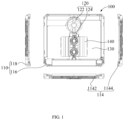
FIG. 1 is a first schematic view of the structure of an electromagnetic heating device according to an embodiment of the present application; -
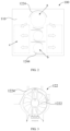
FIG. 2 is a second schematic view of the structure of an electromagnetic heating device according to an embodiment of the present application; -
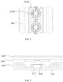
FIG. 3 is a schematic view of the structure of a first air supply part according to an embodiment of the present application; -
FIG. 4 is a third schematic view of the structure of an electromagnetic heating device according to an embodiment of the present application; and -
FIG. 5 is a fourth schematic view of the structure of an electromagnetic heating device according to an embodiment of the present application. - The corresponding relationships between the reference signs and the component names in
FIG. 1 to FIG. 5 are as follows:
100 electromagnetic heating device, 110 housing, 112 air inlet, 114 air outlet, 1142 first air outlet, 1144 second air outlet, 116 bottom plate, 118 side plate, 120 fan assembly, 122 first air supply part, 1222 first fan, 1224 first air guiding rib, 124 second air supply part, 1242 second fan, 1244 second air guiding rib, 130 main board, 140 heat sink, 150 partition plate, 160 panel. - To more clearly understand the above purposes, features and advantages of the present application, the present application will be further detailed hereinafter in combination with the accompanying drawings and embodiments. It should be indicated that in the case of no conflict, the embodiments and the features in the embodiments of the present application can be combined with each other.
- Many details are illustrated in the following description for the convenience of a thorough understanding to the present application, but the present application can further be implemented using other embodiments other than these described herein. Therefore, the protection scope of the present application is not limited to the specific embodiments disclosed in the following text.
- The electromagnetic heating device according to some embodiments of the present application will be described hereinafter referring to
FIG. 1 to FIG. 5 . - As shown in
FIG. 1 andFIG. 2 , an embodiment of the present application provides anelectromagnetic heating device 100, and theelectromagnetic heating device 100 comprises: ahousing 110 comprising anair inlet 112 and anair outlet 114, and theair inlet 112 is located at the bottom of thehousing 110, and theair outlet 114 is located in a peripheral side of thehousing 110; and afan assembly 120, disposed inside thehousing 110 and being opposite to theair inlet 112, and configured to generate an airflow that diffuses toward the peripheral sides of thefan assembly 120. - The present application defines an
electromagnetic heating device 100 that can generate an electromagnetic field. A target container is placed above theelectromagnetic heating device 100, and under the action of the electromagnetic field, the temperature of the target container gradually increases, to cook the food ingredients into finished food through the high-temperature target container. - The
electromagnetic heating device 100 comprises thehousing 110 and thefan assembly 120. Thehousing 110 serves as the main frame structure of theelectromagnetic heating device 100, and is configured to position and support other structures on theelectromagnetic heating device 100, for example, an electromagnetic heating assembly that generates the electromagnetic field is installed inside thehousing 110. And thehousing 110 is provided with theair inlet 112 and theair outlet 114, and thefan assembly 120 is arranged inside thehousing 110. Thefan assembly 120 drives the air to flow within thehousing 110 to generate a heat dissipation airflow. The heat dissipation airflow enters the interior of thehousing 110 through theair inlet 112 and is discharged outside thehousing 110 through theair outlet 114, to carry away the heat from the working structures inside thehousing 110, thus achieving the heat dissipation effect. - In related art, for products such as the multi-head stove and an induction cooker, the electrical members inside the casing generate a large amount of heat during operation. Moreover, part of the heat from the heated target container is further transferred to the interior of the casing. To dissipate the abovementioned heat, a heat dissipating air duct is often constructed inside the casing.
- In related art, to meet the heat dissipation requirement of a multi-head stove, an air inlet and an air outlet oriented in a specific direction are typically provided in a casing. Then the airflow passing through the air inlet and the air outlet sequentially carries away internal heat. However, a single-direction heat-dissipating airflow cannot ensure covering all internal heat-generating structures, and this leads to the technical effects of high heat dissipation pressure and poor heat dissipation effect in the multi-head stove. However, the heat dissipation airflow generated by the air outlet with a single orientation has limited coverage area, and this situation is highly likely to create a heat dissipation dead corner, rendering it impossible to ensure that the heat dissipation airflow can cover all heating structures within the housing. Consequently, the heat dissipation airflow cannot meet the actual heat dissipating demands of the product, resulting in the technical problems of poor heat dissipation effect, low safety, and a high failure rate of the product.
- In this regard, in the
electromagnetic heating device 100 defined in the present application, theair inlet 112 is provided at the bottom of thehousing 110, while theair outlet 114 is provided in the peripheral side of thehousing 110, and theair outlet 114 can face a plurality of directions in the peripheral side of thehousing 110. On this basis, thefan assembly 120 is arranged relative to theair inlet 112. When activated, thefan assembly 120 diffuses the air drawn in from theair inlet 112 to the peripheral side of thefan assembly 120, and the diffused airflow finally gathers in the area where theair outlet 114 is located and is discharged out of thehousing 110 through theair outlet 114. By arranging theair inlet 112 and theair outlet 114 in the above manner and providing afan assembly 120 that can diffuse airflow in all directions, the diffused airflow can cover the entire internal space of thehousing 110, and this allows the heating structures around thefan assembly 120 to come into contact with the heat dissipation airflow and perform heat exchange with the heat dissipation airflow. Even if there is noair outlet 114 in a certain direction, the airflow moving in that direction can still dissipate the heat for the heating members in the area it passes through, and finally gather at theair outlet 114 and is discharged through theair outlet 114. - Thus, it can be seen that the present application overcomes the technical defects of high heat dissipation pressure and poor heat dissipation effect of the product in related art by providing the
air outlet 114 in the peripheral side of thehousing 110 and providing thefan assembly 120 that diffuses airflow in all directions. Furthermore, the technical effects of optimizing the structural layout ofelectromagnetic heating device 100, improving the safety and reliability ofelectromagnetic heating device 100, and reducing the failure rate ofelectromagnetic heating device 100 are achieved. - As shown in
FIG. 1 andFIG. 2 , in some embodiments, theair outlet 114 comprises: afirst air outlet 1142 located on the front side and/or the rear side of thehousing 110; asecond air outlet 1144 located at the left side and/or the right side of thehousing 110. - In this embodiment, the orientation of the
air outlet 114 is defined. Specifically, the peripheral side of thehousing 110 comprises a front side, a rear side, a left side and a right side. According to the orientation of theair outlet 114, it is divided into thefirst air outlet 1142 and thesecond air outlet 1144. And thefirst air outlet 1142 is provided on the front side and/or the rear side of thehousing 110, and thesecond air outlet 1144 is provided on the left side and/or the right side of thehousing 110. That is, theair outlet 114 can be arranged in two adjacent directions in the peripheral side of thehousing 110, or theair outlet 114 can further be arranged in all four directions in the peripheral side of thehousing 110. By arranging theair outlet 114 in at least two adjacent directions, the coverage area of the heat dissipation airflow inside thehousing 110 can be expanded, and this can avoid that the heat dissipation airflow gathering in a single direction cannot cover the internal space of theentire housing 110 and then a heat dissipation dead corner is generated. Furthermore, the technical effects of optimizing the distribution of theair outlet 114, improving the coverage of the heat dissipation airflow, enhancing heat dissipation efficiency, and improving the safety and reliability of theelectromagnetic heating device 100 are achieved. - In some embodiments, the
first air outlet 1142 is only provided on the front side of thehousing 110 or the rear side of thehousing 110; thesecond air outlet 1144 is provided on both the left side of thehousing 110 and the right side of thehousing 110. - In this embodiment, the orientation of the
air outlet 114 is further defined. Specifically, thesecond air outlet 1144 is provided on both the left side of thehousing 110 and the right side of thehousing 110. Thefirst air outlet 1142 is only provided on one side of the front and rear sides of thehousing 110. By defining the above distribution manner of theair outlet 114 in which air is discharged from three sides, it is possible to improve the intensity of the heat dissipation airflow by appropriately reducing the orientation of theair outlet 114 and the total area of theair outlet 114 on the basis of ensuring that the coverage of the internal space of thehousing 110 by the heat dissipation airflow meets the heat dissipation requirements, to enhance the heat dissipation efficiency. - Furthermore, the
first air outlet 1142 is only provided on the front side of thehousing 110, and the rear side of theelectromagnetic heating device 100 is often arranged close to the wall. Providing thefirst air outlet 1142 only on the front side of thehousing 110 can avoid the phenomenon that theair outlet 114 is blocked by the wall and the air cannot be discharged smoothly. Furthermore, the technical effect of improving the practicality ofelectromagnetic heating device 100 is achieved. - As shown in
FIG. 1 andFIG. 2 , in some embodiments, thefan assembly 120 comprises: a firstair supply part 122, spaced apart from thefirst air outlet 1142 and configured to deliver airflow to thefirst air outlet 1142; a secondair supply part 124, arranged between the firstair supply part 122 and thefirst air outlet 1142 and configured to deliver airflow to thesecond air outlet 1144. - In this embodiment, the
fan assembly 120 comprises the firstair supply part 122 and the secondair supply part 124. Specifically, the firstair supply part 122 is spaced apart from thefirst air outlet 1142, and the secondair supply part 124 is provided between thefirst air outlet 1142 and the firstair supply part 122. Taking only providing thefirst air outlet 1142 on the front side of thehousing 110 as an example, the firstair supply part 122 is provided near the rear side of thehousing 110, and the secondair supply part 124 is provided on the front side of the firstair supply part 122. Taking providing thefirst air outlet 1142 on both of the front side and the rear side of thehousing 110 as an example, the firstair supply part 122 is provided in a central area, and the secondair supply part 124 is provided on both of the front side and the rear side of the firstair supply part 122. - The first
air supply part 122 is configured to generate a first airflow flowing towards thefirst air outlet 1142, that is, the first airflow flows from thefirst air outlet 1142 towards the front side and/or the rear side of thehousing 110 to cover the heating structure in the front and rear spaces of the firstair supply part 122 through the first airflow. The secondair supply part 124 simultaneously delivers a second airflow to the twosecond air outlets 1144 in the left and right sides of thehousing 110, and the second airflow mainly carries away the heat from the heating structures on the left and right sides of the secondair supply part 124. By arranging the secondair supply part 124 between the firstair supply part 122 and thefirst air outlet 1142, the first airflow and the second airflow can intersect and converge on the left and right sides of thesecond air outlet 1144, to improve the heat dissipation efficiency of the space on the left and right sides of the secondair supply part 124. Furthermore, the technical effects of improving the heat dissipation effect of theelectromagnetic heating device 100 and enhancing the safety and reliability ofelectromagnetic heating device 100 are achieved. - Furthermore, the heating structures within the
housing 110 are concentrated on the left and right sides of the secondair supply part 124, to achieve centralized heat dissipation through the intersecting first and second airflows. - In
FIG. 2 , the area pointed to by arrow a is the arrangement area of the first air supply part, the area pointed to by arrow b is the arrangement area of the second air supply part, and the area pointed to by arrow c is the area on the left and right sides of the second air supply part, that is, the area where the first airflow and the second airflow intersect and converge. - The thick arrows indicate the flow directions of the first airflow and the second airflow.
- In some embodiments, a plurality of second
air supply parts 124 are provided between the firstair supply part 122 and thefirst air outlet 1142. - In this embodiment, a plurality of second
air supply parts 124 are provided between the firstair supply part 122 and thefirst air outlet 1142. Each secondair supply part 124 delivers the second airflow to thesecond air outlets 1144 on both the left and right sides, to jointly conduct heat dissipation for the heating structures on the left and right sides through the plurality of secondair supply parts 124. - By arranging a plurality of second
air supply parts 124 between the firstair supply part 122 and thefirst air outlet 1142, the heat dissipation pressure on the left and right sides can be shared, and thus this reduces the air supply demand of a single secondair supply part 124, and then reduces the size of a single secondair supply part 124 to avoid excessive occupation of the space on the left and right sides by an overly large secondair supply part 124, to provide convenient conditions for the layout of the heating structures inside thehousing 110. As a result, the technical effects of improving the utilization rate of the heat dissipation airflow and enhancing the heat dissipation efficiency are achieved. - In some embodiments, the
air inlet 112 extends along a first direction, and the firstair supply part 122 and the secondair supply part 124 are distributed along the first direction; the first direction is from the front side of thehousing 110 to the rear side of thehousing 110. - In this embodiment, the shape of the
air inlet 112 and the corresponding distribution manner of the air supply parts are described. Specifically, theair inlet 112 is strip-shaped, and the strip-shapedair inlet 112 extends along the first direction at the bottom of thehousing 110. The first direction is from the front side of thehousing 110 to the rear side of thehousing 110, that is, the thickness direction of thehousing 110. On this basis, the firstair supply part 122 and the secondair supply part 124 further extend along the thickness direction, to reduce the occupation of the space on the left and right sides of the air supply parts as much as possible, and provide convenient conditions for the rational layout of the heating structures. - Furthermore, the
air inlet 112 is distributed along the middle line of thehousing 110, to divide the space into two symmetrical spaces on the left and right sides of theair inlet 112, and thus this enhances the uniformity of the heat dissipation airflow, reduces the possibility of the appearance of obvious strong heat dissipation area and weak heat dissipation area, and further enhance the reliability of heat dissipation. - As shown in
FIG. 2 and FIG. 3 , in some embodiments, the firstair supply part 122 comprises: afirst fan 1222, positioned opposite theair inlet 112; and a firstair guiding rib 1224, surrounding thefirst fan 1222 and comprising a first opening 1226 that faces the area between the secondair supply part 124 and thesecond air outlet 1144. - In this embodiment, the structure of the first
air supply part 122 is described. Specifically, the firstair supply part 122 comprises afirst fan 1222 and a firstair guiding rib 1224. The intake side of thefirst fan 1222 faces theair inlet 112 at the bottom of thehousing 110, while the discharge side of thefirst fan 1222 faces all the directions of thefirst fan 1222. Thefirst fan 1222 draws air in from theair inlet 112 and discharges the pressurized air to the surrounding area. The firstair guiding rib 1224 is provided on the peripheral side of thefirst fan 1222 and surrounds thefirst fan 1222, and the firstair guiding rib 1224 is provided with a first opening 1226. The first opening 1226 avoids the secondair supply part 124 and faces the left and right sides of the secondair supply part 124. When thefirst fan 1222 operates, the airflow that is diffused in all directions encounters the firstair guiding rib 1224 and then converges towards the first opening 1226 along the firstair guiding rib 1224. Finally, the airflow flows towards the area that the first opening 1226 faces to form the aforementioned first airflow. - Furthermore, the first
air guiding rib 1224 comprises two first openings 1226, and one of the first openings 1226 faces the left front side of the firstair supply part 122, namely, the area on the left side of the secondair supply part 124, and the other first opening 1226 faces the right front side of the firstair supply part 122, namely, the area on the right side of the secondair supply part 124. The structure complexity of the air supply parts composed of the fan and the air guiding rib is relatively low, which can reduce process complexity and the cost of production and assembly. - As shown in
FIG. 2 andFIG. 4 , in some embodiments, the secondair supply part 124 comprises: asecond fan 1242, positioned opposite theair inlet 112; and a secondair guiding rib 1244, surrounding thesecond fan 1242 and comprising a second opening 1246 that faces thesecond air outlet 1144. - In this embodiment, the structure of the second
air supply part 124 is described. Specifically, the secondair supply part 124 comprises asecond fan 1242 and a secondair guiding rib 1244. The intake side of thesecond fan 1242 faces theair inlet 112 at the bottom of thehousing 110, while the discharge side of thesecond fan 1242 faces all the directions of thesecond fan 1242. Thesecond fan 1242 draws air in from theair inlet 112 and discharges the pressurized air to the surrounding area. The secondair guiding rib 1244 is provided on the peripheral side of thesecond fan 1242 and surrounds thesecond fan 1242, and the secondair guiding rib 1244 is provided with a second opening 1246. The second opening 1246 faces the twosecond air outlets 1244 on the left and right sides of the secondair supply part 124. When thesecond fan 1242 operates, the airflow that is diffused to all directions encounters the secondair guiding rib 1244 and then converges towards the second opening 1246 along the secondair guiding rib 1244. Finally, the airflow is discharged to thesecond air outlets 1144 to form the aforementioned second airflow. - Furthermore, the second
air guiding rib 1244 comprises two second openings 1246, and one of the second openings 1246 faces the area on the left side of the secondair supply part 124 and delivers airflow to thesecond air outlet 1144 on the left side of thehousing 110, and the other second opening 1246 faces the area on the right side of the secondair supply part 124 and delivers airflow to thesecond air outlet 1144 in the right side of thehousing 110. Likewise, the structure complexity of the air supply parts composed of the fan and the air guiding rib is relatively low, which can reduce process complexity and the cost of production and assembly. - In some embodiments, both the
first fan 1222 and thesecond fan 1242 are axial fans. - In this embodiment, axial fans are selected as both the
first fan 1222 and thesecond fan 1242. The axial fans have the characteristic that the internal airflow is parallel to the axial direction of a wind wheel, and the output airflow approaches the radial direction of the wind wheel. This characteristic allows them to adapt to the requirements of bottom air intake and peripheral air exhaust. Additionally, axial fans have a relatively low requirement for size in a height direction, and selecting the axial fan helps reduce the thickness of theelectromagnetic heating device 100, and then reduces the difficulty of arranging and storing theelectromagnetic heating device 100, and improves the practicality of theelectromagnetic heating device 100. - As shown in
FIG. 1 , in some embodiments, the impeller diameter of thefirst fan 1222 is greater than that of thesecond fan 1242. - In this embodiment, based on the previous embodiment, the impeller diameter of the
first fan 1222 is a first diameter, and the impeller diameter of thesecond fan 1242 is a second diameter. Here, the first diameter is greater than the second diameter. - By providing the
first fan 1222 with a larger impeller diameter, the space on the left and right sides of the firstair supply part 122 can be fully utilized to generate strong first airflow by increasing the impeller size, to enhance the heat dissipation effect on the left and right sides of the secondair supply part 124. - By providing the
second fan 1242 with a smaller impeller diameter, it is possible to avoid excessive occupation of the space on the left and right sides by the impeller, reduce the possibility of interference between the secondair supply part 124 and the heating structures, and provide convenient conditions for arranging the heating structures on the left and on the right. - As shown in
FIG. 1 andFIG. 5 , in some embodiments, theelectromagnetic heating device 100 further comprises amain board 130 provided between theair outlet 114 and thefan assembly 120. - In this embodiment, the aforementioned heating structures comprise a
main board 130, and themain board 130 comprises a PCB (Printed Circuit Board), and a control chip, a power supply unit, a sensor, a switch tube, etc. provided on the PCB. Themain board 130 is configured to control the working status of theelectromagnetic heating device 100 to meet the automation and intelligence requirements of theelectromagnetic heating device 100. And themain board 130 generates a large amount of heat after being powered on. If this heat cannot be dissipated in time to the outside, problems such as the circuit breakage of themain board 130, melting and even combustion may occur. In this regard, the present application arranges themain board 130 between theair outlet 114 and thefan assembly 120, specifically between the secondair supply part 124 and thesecond air outlet 1144, to jointly cool themain board 130 through the aforementioned first airflow and second airflow, to reduce the possibility of the occurrence of the above problems of themain board 130 and then achieve the technical effect of improving the safety and reliability of theelectromagnetic heating device 100. - In some embodiments, the
electromagnetic heating device 100 further comprises aheat sink 140, arranged on themain board 130. - In this embodiment, the
electromagnetic heating device 100 further comprises aheat sink 140, arranged on themain board 130 and located within the coverage range of the first airflow and the second airflow. Theheat sink 140 has excellent thermal conductivity and an aluminumalloy heat sink 140 can be specifically chosen. During operation, the heat generated by themain board 130 is transferred to theheat sink 140 through contact. As the first airflow and the second airflow flow through theheat sink 140, the heat inside theheat sink 140 is quickly dissipated into the first airflow and the second airflow, to accelerate the heat dissipation efficiency of themain board 130, and then enhance the heat dissipation effect without changing fan power. - In some embodiments, the
housing 110 comprises: abottom plate 116, with theair inlet 112 arranged in thebottom plate 116; aside plate 118, which is connected to thebottom plate 116 and surrounds thebottom plate 116. Theair outlet 114 is arranged on theside plate 118. - In this embodiment, the structure of the
housing 110 is described. Specifically, thehousing 110 comprises abottom plate 116 and aside plate 118. Theair inlet 112 is provided on thebottom plate 116. Theside plate 118 surrounds thebottom plate 116, and theair outlet 114 is provided in theside plate 118. Thebottom plate 116 and theside plate 118 enclose a cavity body. Themain board 130, thefan assembly 120, and theheat sink 140 are all provided within the cavity body to conceal and protect the abovementioned internal structures through thehousing 110. - The
side plate 118 is detachably provided on thebottom plate 116. By setting thedetachable side plate 118, firstly, the processing difficulty of thehousing 110 can be reduced, and secondly, when aside plate 118 on a certain side is damaged or theair outlet 114 on it is blocked, users can replace or clean theside plate 118 by detaching thecorresponding side plate 118. This reduces the maintenance difficulty of thehousing 110 and provides convenience for users. - In some embodiments, the
electromagnetic heating device 100 further comprises apartition plate 150, which is connected to theside plate 118 and spaced apart from thebottom plate 116. Thefan assembly 120, themain board 130, and theheat sink 140 are all located between thepartition plate 150 and thebottom plate 116. - In this embodiment, the
electromagnetic heating device 100 further comprises apartition plate 150. Thepartition plate 150 is connected to theside plate 118, and thepartition plate 150 is spaced apart from thebottom plate 116. Thepartition plate 150 is located at the top of thefan assembly 120, themain board 130, and theheat sink 140. By providing thepartition plate 150, it can cooperate with thebottom plate 116, theside plate 118, and the aforementioned air guiding rib to enclose an air supply channel. Firstly, it can increase the airflow intensity by collecting the airflow to enhance the heat dissipation effect, and secondly, it can prevent the airflow from leaking out from the top, to further improve the heat dissipation effect and reduce energy consumption. - In some embodiments, the
electromagnetic heating device 100 further comprises apanel 160 arranged at the top of thehousing 110. - In this embodiment, the
electromagnetic heating device 100 further comprises apanel 160. Thepanel 160 is placed above theside plate 118. Firstly, users cover the opening at the top of thehousing 110 to conceal the working structures inside thehousing 110, and secondly, thepanel 160 is configured to support a target container. Specifically, an electromagnetic coil inside thehousing 110 forms a heating area on thepanel 160. The target container is placed above the heating area. Under the action of the electromagnetic field generated by the electromagnetic coil, the target container gradually heats up, to cook the food ingredients inside it at a high temperature. - It needs to be indicated that in the claims, specification and the accompanying drawings of the specification of the present application, the term of "a plurality of" refers to two or more than two, unless otherwise clearly defined. The orientation or position relations indicated by the terms of "upper", "lower" and the like are based on the orientation or position relations shown in the accompanying drawings, and are just intended to conveniently describe the present application and simplify the description, and are not intended to indicate or imply that the devices or units as indicated should have specific orientations or should be configured or operated in specific orientations, and then such description should not be construed as limitations to the present application. The terms "connect", "install", "fix" and the like should be understood in a broad sense, for example, the term "connect" can be a fixed connection between a plurality of objects, a detachable connection between a plurality of objects, or an integral connection; it can be a direct connection between a plurality of objects, or an indirect connection between a plurality of objects through an intermediate medium. For those of ordinary skills in this field, the specific meanings of the above terms in the present application can be understood according to the specific situations of the above data.
- In the claims, the description and the accompanying drawings of the description of the present application, the description of the terms of "an embodiment", "some embodiments", "specific embodiment" and the like is intended to mean that the specific features, structures, materials or characteristics described in combination with the embodiments or examples are included in at least one embodiment or example of the present application. In the claims, the description and the accompanying drawings of the description, the illustrative expression of the above terms may not indicate the same embodiment or example. In addition, the specific features, structures, materials or characteristics as described may be combined with each other in an appropriate method in one or more of any embodiments or examples.
- The above-mentioned are merely some embodiments of the present application and not intended to limit the present application, and for one skilled in the art, various modifications and changes may be made to the present application. Any modifications, equivalent substitutions, improvements and so on made within the spirit and principle of the present application should be covered within the scope of protection of the present application.
Claims (15)
- An electromagnetic heating device, comprising:a housing comprising an air inlet and an air outlet, wherein the air inlet is located at the bottom of the housing, and the air outlet is located on a peripheral side of the housing; anda fan assembly, disposed inside the housing and opposite to the air inlet, and configured to generate an airflow that diffuses toward the peripheral side of the fan assembly.
- The electromagnetic heating device according to claim 1, wherein the air outlet comprises:a first air outlet located at a front side and/or a rear side of the housing; anda second air outlet located at a left side and/or the right side of the housing.
- The electromagnetic heating device according to claim 2, wherein:the first air outlet is only provided on the front side of the housing or the rear side of the housing; andthe second air outlet is provided on both the left side of the housing and the right side of the housing.
- The electromagnetic heating device according to claim 2, wherein the fan assembly comprises:a first air supply part, spaced apart from the first air outlet, and configured to deliver airflow to the first air outlet; anda second air supply part, arranged between the first air supply part and the first air outlet, configured to deliver airflow to the second air outlet.
- The electromagnetic heating device according to claim 4, wherein a plurality of the second air supply parts are provided between the first air supply part and the first air outlet.
- The electromagnetic heating device according to claim 4, wherein:the air inlet extends along a first direction, and the first air supply part and the second air supply part are distributed along the first direction; andthe first direction is from the front side of the housing to the rear side of the housing.
- The electromagnetic heating device according to claim 4, wherein the first air supply part comprises:a first fan, positioned opposite the air inlet; anda first air guiding rib, surrounding the first fan and comprising a first opening that faces the area between the second air supply part and the second air outlet.
- The electromagnetic heating device according to claim 7, wherein the second air supply part comprises:a second fan, positioned opposite the air inlet; anda second air guiding rib, surrounding the second fan and comprising a second opening that faces the second air outlet.
- The electromagnetic heating device according to claim 8, wherein both the first fan and the second fan are axial fans.
- The electromagnetic heating device according to claim 9, wherein the impeller diameter of the first fan is greater than that of the second fan.
- The electromagnetic heating device according to any one of claims 1 to 10, further comprising:
a main board provided between the air outlet and the fan assembly. - The electromagnetic heating device according to claim 11, further comprising:
a heat sink, arranged on the main board. - The electromagnetic heating device according to claim 12, wherein the housing comprises:a bottom plate, with the air inlet arranged on the bottom plate; anda side plate, connected to the bottom plate and surrounding the bottom plate, wherein the air outlet is arranged on the side plate.
- The electromagnetic heating device according to claim 13, further comprising:
a partition plate, connected to the side plate and spaced apart from the bottom plate, wherein the fan assembly, the main board, and the heat sink are all located between the partition plate and the bottom plate. - The electromagnetic heating device according to any one of claims 1 to 10, further comprising:
a panel, arranged at the top of the housing.
Applications Claiming Priority (2)
| Application Number | Priority Date | Filing Date | Title |
|---|---|---|---|
| CN202222333091.3U CN218162922U (en) | 2022-09-02 | 2022-09-02 | Electromagnetic heating equipment |
| PCT/CN2023/115726 WO2024046348A1 (en) | 2022-09-02 | 2023-08-30 | Electromagnetic heating device |
Publications (2)
| Publication Number | Publication Date |
|---|---|
| EP4583636A1 true EP4583636A1 (en) | 2025-07-09 |
| EP4583636A4 EP4583636A4 (en) | 2025-12-24 |
Family
ID=84558914
Family Applications (1)
| Application Number | Title | Priority Date | Filing Date |
|---|---|---|---|
| EP23859377.6A Pending EP4583636A4 (en) | 2022-09-02 | 2023-08-30 | ELECTROMAGNETIC HEATING DEVICE |
Country Status (4)
| Country | Link |
|---|---|
| EP (1) | EP4583636A4 (en) |
| KR (1) | KR20250060228A (en) |
| CN (1) | CN218162922U (en) |
| WO (1) | WO2024046348A1 (en) |
Families Citing this family (1)
| Publication number | Priority date | Publication date | Assignee | Title |
|---|---|---|---|---|
| CN218162922U (en) * | 2022-09-02 | 2022-12-27 | 佛山市顺德区美的电热电器制造有限公司 | Electromagnetic heating equipment |
Family Cites Families (7)
| Publication number | Priority date | Publication date | Assignee | Title |
|---|---|---|---|---|
| TWI367719B (en) * | 2009-03-02 | 2012-07-01 | Delta Electronics Inc | Electric device and circling dissipating system using the same |
| CN102644944B (en) * | 2012-03-30 | 2014-07-23 | 九阳股份有限公司 | Ultrathin electromagnetic oven capable of efficiently cooling |
| JP5667316B1 (en) * | 2014-02-24 | 2015-02-12 | アイリスオーヤマ株式会社 | Electromagnetic cooker |
| CN204962883U (en) * | 2015-08-06 | 2016-01-13 | 佛山市顺德区美的电热电器制造有限公司 | Electromagnetic oven |
| CN106060991B (en) * | 2016-07-11 | 2022-12-13 | 珠海格力电器股份有限公司 | Induction cooker air duct structure and induction cooker |
| CN211130712U (en) * | 2019-11-04 | 2020-07-31 | 佛山市顺德区美的电热电器制造有限公司 | Cooking utensil |
| CN218162922U (en) * | 2022-09-02 | 2022-12-27 | 佛山市顺德区美的电热电器制造有限公司 | Electromagnetic heating equipment |
-
2022
- 2022-09-02 CN CN202222333091.3U patent/CN218162922U/en active Active
-
2023
- 2023-08-30 KR KR1020257009422A patent/KR20250060228A/en active Pending
- 2023-08-30 EP EP23859377.6A patent/EP4583636A4/en active Pending
- 2023-08-30 WO PCT/CN2023/115726 patent/WO2024046348A1/en not_active Ceased
Also Published As
| Publication number | Publication date |
|---|---|
| KR20250060228A (en) | 2025-05-07 |
| WO2024046348A1 (en) | 2024-03-07 |
| EP4583636A4 (en) | 2025-12-24 |
| CN218162922U (en) | 2022-12-27 |
Similar Documents
| Publication | Publication Date | Title |
|---|---|---|
| CN206892786U (en) | A kind of computer water-cooling radiating device | |
| WO2022100117A1 (en) | Embedded cooking appliance and cooking system | |
| CN215112777U (en) | Bottom plate subassembly and cooking device | |
| CN110464199B (en) | Cooking equipment and a kind of deep pot body thereof | |
| CN218162922U (en) | Electromagnetic heating equipment | |
| CN209627986U (en) | Heat radiation structure and have its motor frequency conversion controller | |
| US20250120542A1 (en) | High energy efficient air fryer | |
| CN222338362U (en) | An energy storage system | |
| CN209346711U (en) | A kind of cabinets cavity ventilating system | |
| CN206024399U (en) | Food cooking machine | |
| CN211792618U (en) | High-efficient cooling system of UPS | |
| CN213365412U (en) | Computer casing | |
| CN211352903U (en) | Power amplifier capable of effectively dissipating heat | |
| CN223976084U (en) | Air duct heat dissipation device and commercial electromagnetic boiler | |
| CN112594744B (en) | Cooking utensil | |
| CN224055830U (en) | Safe in utilization's air fryer | |
| CN220648335U (en) | Integrated kitchen range | |
| CN207799570U (en) | A kind of high-efficient heat-dissipating computer housing | |
| CN107529314B (en) | Thermal design layout method of modular active filter device | |
| CN223345445U (en) | Electromagnetic oven | |
| CN206163961U (en) | Distribution cabinet | |
| CN217496533U (en) | Unmanned plane | |
| CN223695651U (en) | Air duct structure of air fryer and air fryer | |
| CN112393281A (en) | Embedded cooking utensil and cooking system | |
| CN224140634U (en) | An air fryer with high heat dissipation |
Legal Events
| Date | Code | Title | Description |
|---|---|---|---|
| STAA | Information on the status of an ep patent application or granted ep patent |
Free format text: STATUS: THE INTERNATIONAL PUBLICATION HAS BEEN MADE |
|
| PUAI | Public reference made under article 153(3) epc to a published international application that has entered the european phase |
Free format text: ORIGINAL CODE: 0009012 |
|
| STAA | Information on the status of an ep patent application or granted ep patent |
Free format text: STATUS: REQUEST FOR EXAMINATION WAS MADE |
|
| 17P | Request for examination filed |
Effective date: 20250402 |
|
| AK | Designated contracting states |
Kind code of ref document: A1 Designated state(s): AL AT BE BG CH CY CZ DE DK EE ES FI FR GB GR HR HU IE IS IT LI LT LU LV MC ME MK MT NL NO PL PT RO RS SE SI SK SM TR |
|
| REG | Reference to a national code |
Ref country code: DE Ref legal event code: R079 Free format text: PREVIOUS MAIN CLASS: H05B0006020000 Ipc: H05B0006120000 |
|
| DAV | Request for validation of the european patent (deleted) | ||
| DAX | Request for extension of the european patent (deleted) | ||
| A4 | Supplementary search report drawn up and despatched |
Effective date: 20251124 |
|
| RIC1 | Information provided on ipc code assigned before grant |
Ipc: H05B 6/12 20060101AFI20251118BHEP |