EP4583608A1 - User equipment, radio access network node, and method therefor - Google Patents
User equipment, radio access network node, and method therefor Download PDFInfo
- Publication number
- EP4583608A1 EP4583608A1 EP23859976.5A EP23859976A EP4583608A1 EP 4583608 A1 EP4583608 A1 EP 4583608A1 EP 23859976 A EP23859976 A EP 23859976A EP 4583608 A1 EP4583608 A1 EP 4583608A1
- Authority
- EP
- European Patent Office
- Prior art keywords
- initial
- bwp
- bwps
- select
- configuration information
- Prior art date
- Legal status (The legal status is an assumption and is not a legal conclusion. Google has not performed a legal analysis and makes no representation as to the accuracy of the status listed.)
- Pending
Links
Images




Classifications
-
- H—ELECTRICITY
- H04—ELECTRIC COMMUNICATION TECHNIQUE
- H04W—WIRELESS COMMUNICATION NETWORKS
- H04W48/00—Access restriction; Network selection; Access point selection
- H04W48/08—Access restriction or access information delivery, e.g. discovery data delivery
- H04W48/12—Access restriction or access information delivery, e.g. discovery data delivery using downlink control channel
-
- H—ELECTRICITY
- H04—ELECTRIC COMMUNICATION TECHNIQUE
- H04W—WIRELESS COMMUNICATION NETWORKS
- H04W74/00—Wireless channel access
- H04W74/002—Transmission of channel access control information
- H04W74/006—Transmission of channel access control information in the downlink, i.e. towards the terminal
-
- H—ELECTRICITY
- H04—ELECTRIC COMMUNICATION TECHNIQUE
- H04W—WIRELESS COMMUNICATION NETWORKS
- H04W72/00—Local resource management
- H04W72/04—Wireless resource allocation
- H04W72/044—Wireless resource allocation based on the type of the allocated resource
- H04W72/0453—Resources in frequency domain, e.g. a carrier in FDMA
-
- H—ELECTRICITY
- H04—ELECTRIC COMMUNICATION TECHNIQUE
- H04W—WIRELESS COMMUNICATION NETWORKS
- H04W74/00—Wireless channel access
- H04W74/08—Non-scheduled access, e.g. ALOHA
- H04W74/0833—Random access procedures, e.g. with 4-step access
-
- H—ELECTRICITY
- H04—ELECTRIC COMMUNICATION TECHNIQUE
- H04L—TRANSMISSION OF DIGITAL INFORMATION, e.g. TELEGRAPHIC COMMUNICATION
- H04L5/00—Arrangements affording multiple use of the transmission path
- H04L5/0001—Arrangements for dividing the transmission path
- H04L5/0003—Two-dimensional division
- H04L5/0005—Time-frequency
- H04L5/0007—Time-frequency the frequencies being orthogonal, e.g. OFDM(A) or DMT
- H04L5/001—Time-frequency the frequencies being orthogonal, e.g. OFDM(A) or DMT the frequencies being arranged in component carriers
Definitions
- the present disclosure relates to radio communication systems, and in particular to signaling between a radio access network node and a user equipment (UE).
- UE user equipment
- RedCap Reduced Capability
- FR1 i.e., sub-6 GHz band
- FR2 i.e., millimeter wave (mmWave) band
- CA Carrier Aggregation
- MR-DC Multi-Radio Dual Connectivity
- DAPS Dual Active Protocol Stack
- IAB Integrated Access and Backhaul
- One of the objectives to be achieved by the example embodiments disclosed herein is to provide apparatus, methods, and programs that contribute to providing specific methods for notifying a particular type of UE (e.g., RedCap UEs) of multiple initial DL BWPs and multiple initial UL BWPs that are specific to or dedicated to that particular type of UE. It should be noted that this object is only one of the objects to be achieved by the example embodiments disclosed herein. Other objects or problems and novel features will become apparent from the following description and the accompanying drawings.
- a particular type of UE e.g., RedCap UEs
- multiple example embodiments described below may be implemented independently or in any combination of two or more, as appropriate. These multiple example embodiments have novel features that differ from one another. Accordingly, these multiple example embodiments contribute to achieving different objectives or solving different problems and contribute to achieving different advantages.
- LTE Long Term Evolution
- 5G 5th generation mobile communication system
- LTE Long Term Evolution
- LTE-Advanced improvements and enhancements to LTE and LTE-Advanced to enable interworking with 5G systems, unless otherwise specified.
- the RAN node 1 is deployed in a RAN.
- the RAN node 1 may be an NG-RAN node, specifically a gNB or ng-eNB.
- An ng-eNB is a node that provides E-UTRA user plane and control plane protocol termination to a UE and is connected to a 5G Core Network (5GC) via NG interfaces.
- the RAN node 1 may be a combination of a Central Unit (CU) (e.g., gNB-CU or eNB-CU) and one or more Distributed Units (DUs) (e.g., gNB-DUs or eNB-DUs) in a cloud RAN (C-RAN) deployment.
- CU Central Unit
- DUs Distributed Units
- the RAN node 1 serves a cell 10 to multiple types of UEs 2. These multiple types of UEs 2 use the cell 10 as their serving cell and perform Contention Based Random Access (CBRA) in the cell 10.
- the RAN node 1 may further serve one or more other cells.
- the cell 10 may be a primary cell (PCell) in Carrier Aggregation (CA), and one or more other cells may be secondary cells (SCells). That is, the cell 10 is a cell in which UEs 2 in RRC_IDLE initiate an RRC connection establishment procedure.
- UEs 2 in RRC_INACTIVE may initiate an RRC connection resume procedure in the cell 10.
- UEs 2 in RRC_CONNECTED may initiate an RRC connection re-establishment procedure in the cell 10.
- the RAN node 1 broadcasts the Minimum SI (i.e., MIB and SIB1) in the cell 10.
- the RAN node 1 may also transmit other SI.
- the Other SI contains all SIBs that are not always broadcast within the Minimum SI. These SIBs are broadcast periodically on a DL Shared Channel (DL-SCH), broadcast on demand on a DL-SCH (i.e., upon request from UEs in RRC_IDLE or RRC_INACTIVE), or sent in a dedicated manner on a DL_SCH to UEs in RRC_CONNECTED.
- DL-SCH DL Shared Channel
- RRC_IDLE or RRC_INACTIVE i.e., upon request from UEs in RRC_IDLE or RRC_INACTIVE
- the UEs 2 may be referred to by other names such as radio terminals, mobile terminals, mobile stations, or wireless transmit receive units (WTRUs).
- the UEs 2 may be implemented in machines, vehicles, or devices.
- the UEs 2 may be implemented in machines, vehicles, or devices with mobility, and in particular in automated guided vehicles (AGVs), mobile robots, construction machines, or unmanned or uncrewed aerial vehicles (UAVs).
- AGVs automated guided vehicles
- UAVs unmanned or uncrewed aerial vehicles
- Each UE 2 performs cell selection or cell reselection when it is in RRC_IDLE or RRC_INACTIVE. In addition, each UE 2 may perform RRC connection re-establishment when it is in RRC_CONNECTED state.
- Each UE 2 receives MIB and SIB1 in the cell 10 and configures the initial DL BWP and initial UL BWP based on cell-specific common parameters for the initial DL BWP and initial UL BWP in the cell 10 contained in SIB1.
- Each UE 2 then uses the Initial DL BWP and Initial UL BWP to perform a random access procedure in the cell 10 and initiate an RRC connection establishment, resume, or re-establishment procedure.
- the UEs 2 are divided into first type and second type.
- Second type UEs are UEs with limited capabilities compared to first type UEs.
- the second type of UE may have limited RF capability compared to the first type of UE.
- the second type of UE may be a RedCap UE.
- the first type of UE may be referred to as a normal UE or a non-RedCap UE.
- the second type of UE is considered to be a RedCap UE and the first type of UE is considered to be a Normal UE or a Non-RedCap UE.
- a RedCap UE has reduced capabilities with the intention to have lower complexity with respect to non-RedCap UEs.
- FR1 i.e., sub-6 GHz band
- FR2 i.e., millimeter wave (mmWave) band.
- functions related to CA, MR-DC, DAPS, and IAB are not supported by RedCap UEs.
- RedCap UEs For example, for RedCap UEs, the minimum number of UE Rx branches and the maximum number of DL MIMO layers are reduced or relaxed compared to those for non-RedCap UEs.
- FR1 one DL MIMO layer is supported if one Rx branch is supported, and two DL MIMO layers are supported if two Rx branches are supported.
- FR2 one or two DL MIMO layers can be supported, and two Rx branches are always supported.
- the UE functions and corresponding capabilities for more than two UE Rx branches or more than two DL MIMO layers, and the UE functions and capabilities for more than two UE Tx branches or more than two UL MIMO layers are not supported by RedCap UEs.
- RedCap UEs may support time division duplex (TDD) or half-duplex frequency division duplex (HD-FDD). For HD-FDD, RedCap UEs can share an antenna and radio frequency (RF) components for uplink transmission and downlink reception.
- TDD time division duplex
- RedCap UEs in RRC_IDLE and RRC_INACTIVE monitor paging only in the (default or RedCap-specific) initial DL BWP associated with the CD-SSB and perform cell (re)selection and measurements in the CD-SSB. If the initial UL BWP is configured for RedCap, RedCap-specific, or RedCap-dedicated, RedCap UEs in RRC_IDLE and RRC_INACTIVE use only the RedCap-specific initial UL BWP to perform random access (or RACH).
- the initial DL BWP for RedCap can be configured with a Type-1 common search space to receive a PDCCH carrying a DCI for a random access MSG2, MSGB, and MSG4, i.e., a PDSCH.
- This DCI is a DCI format with Cyclic Redundancy Check (CRC) bits scrambled with a Random Access Radio Network Temporary Identifier (RA-RNTI).
- CRC Cyclic Redundancy Check
- RA-RNTI Random Access Radio Network Temporary Identifier
- a RedCap UE searches in the Type-1 common search space configured in the initial DL BWP for RedCap to receive a DCI/PDCCH indicating a PDSCH carrying MSG2, MSGB, or MSG4, and receives MSG2, MSGB, or MSG4 based on the received DCI.
- the initial DL BWP for RedCap, specific to RedCap, or dedicated to RedCap may be configured with a search space for paging. However, if the initial DL BWP for RedCap does not contain the CD-SSB and the entire CORESET#0, no search space for paging is configured in the initial DL BWP for RedCap. If the initial DL BWP for RedCap is not configured with a search space for paging, RedCap UEs will not receive paging in that DL BWP. In this case, RedCap UEs may receive paging in the initial DL BWP used by normal UEs or non-RedCap UEs, i.e., the non-RedCap-specific initial DL BWP.
- the RAN node 1 transmits a first initial BWP configuration and a second initial BWP configuration in SIB1.
- the first initial BWP configuration contains common or cell-specific parameters for a first initial BWP in the cell 10.
- the first initial BWP includes an initial DL BWP and an initial UL BWP.
- the first initial DL BWP and UL BWP are used by the first type of UEs, i.e., normal UEs or non-RedCap UEs, that use the cell 10 as a serving cell.
- the first initial DL BWP and UL BWP are used by normal UEs or non-RedCap UEs when accessing the cell 10 to transition from RRC_IDLE or RRC_INACTIVE to RRC_CONNECTED.
- the first initial DL BWP can be used by normal UEs or non-RedCap UEs to receive paging.
- the first initial DL BWP can be configured with a search space to receive a DCI format with CRC bits scrambled with a Paging RNTI (P-RNTI).
- P-RNTI Paging RNTI
- the first initial DL BWP can be used by RedCap UEs to receive paging.
- RedCap UEs may receive paging in the first initial DL BWP used by normal UEs or non-RedCap UEs, or in the search space for paging within the first initial DL BWP.
- the second initial BWP configuration contains cell-specific common parameters for a second initial BWP in the cell 10.
- the second initial BWP includes an initial DL BWP and an initial UL BWP.
- the second initial DL BWP and UL BWP are used by the second type of UEs, i.e., RedCap UEs, that use the cell 10 as a serving cell.
- the second initial DL BWP and UL BWP are used by RedCap UEs when accessing the cell 10 to transition from RRC_IDLE or RRC_INACTIVE to RRC_CONNECTED.
- the second initial DL BWP and UL BWP are the initial DL BWP and UL BWP for RedCap or specific to RedCap.
- the RAN node 1 may configure a plurality of second initial DL BWPs and a plurality of second initial UL BWPs in the cell 10.
- the RAN node 1 may configure a plurality of initial DL BWPs and a plurality of initial UL BWPs in the cell 10 that are specific or dedicated to RedCap UEs.
- the following example embodiments provide details on how to configure a plurality of initial DL BWPs and a plurality of initial UL BWPs specific to RedCap UEs and how they are used by RedCap UEs.
- An example configuration of a radio communication system according to this example embodiment may be the same as the example shown in Fig. 1 .
- This example embodiment provides improved signaling between the RAN node 1 and UEs 2.
- Fig. 2 shows an example of signaling between the RAN node 1 and a UE 2.
- the RAN node 1 transmits SIB1 to the UE 2.
- the RAN node 1 broadcasts SIB1 in the cell 10 and the UE 2 receives the SIB1.
- the SIB1 contains configuration information for a plurality of (second) initial DL BWPs and a plurality of (second) initial UL BWPs that are specific or dedicated to RedCap UEs.
- the SIB1 further contains configurations of a (first) initial DL BWP and a (first) initial UL BWP used by normal UEs or non-RedCap UEs.
- the UE 2 selects an initial DL BWP and an initial UL BWP to be used for random or initial access to the cell 10, from the plurality of initial DL BWPs and the plurality of initial UL BWPs that are specific or dedicated to RedCap.
- the UE 2 transmits a Physical PRACH (PRACH) and a Physical Uplink Shared Channel (PUSCH) for random access in the selected initial UL BWP.
- PRACH Physical PRACH
- PUSCH Physical Uplink Shared Channel
- the UE 2 transmits a random access preamble (MSG1, MSGA) and a PUSCH (MSGA, MSG3) in the selected initial UL BWP.
- the UE 2 receives a PDCCH and a PDSCH, i.e., RAR (MSG2) and Contention Resolution (MSG4, MSGB), for random access in the selected initial DL BWP.
- RAR MSG2
- MSGB Contention Resolution
- the RAN node 1 can provide configuration information of a plurality of initial DL BWPs and a plurality of initial UL BWPs that are specific or dedicated to RedCap to UEs 2 in the cell 10 via SIB 1, i.e., via broadcast.
- Fig. 3 shows an example of the message structure or format of the SIB1.
- SIB1 300 includes a servingCellConfigCommon field, i.e., ServingCellConfigCommonSIB IE 310.
- the ServingCellConfigCommonSIB IE 310 includes a downlinkConfigCommon field, i.e., DownlinkConfigCommonSIB IE 320, and an uplinkConfigCommon field, i.e., UplinkConfigCommonSIB IE 330.
- the DownlinkConfigCommonSIB IE 320 includes a frequencyInfoDL field, i.e., FrequencyInfoDL-SIB IE 321, an initialDownlinkBWP field, i.e., BWP-DownlinkCommon IE 322, and an InitialDownlinkBWPList-RedCap field 323.
- the FrequencyInfoDL-SIB IE 321 provides basic parameters about a downlink carrier and the transmission on it.
- the FrequencyInfoDL-SIB IE 321 specifies one or more frequency bands (specifically, one or more NR frequency band numbers) to which the downlink carrier belongs.
- the BWP-DownlinkCommon IE 322 is used to configure common parameters of the (first) initial DL BWP used by normal UEs or non-RedCap UEs. These parameters are "cell specific".
- the BWP-DownlinkCommon IE 322 includes a pdcch-ConfigCommon field or IE.
- the pdcch-ConfigCommon field or IE can specify a Type-1 common search space using a ra-SearchSpace field or IE.
- this field or IE contains a commonSearchSpaceList field or IE that specifies one or more common search spaces (CSSs) within the BWP.
- the commonSearchSpaceList field or IE is a list of up to four SearchSpace IEs. Each SearchSpace IE specifies a SearchSpaceId and defines the method and location for searching for Physical Downlink Control Channel (PDCCH) candidates.
- PDCH Physical Downlink Control Channel
- the InitialDownlinkBWPList-RedCap field 323 is used to configure common parameters of one or more initial DL BWPs specific or dedicated to RedCap UEs. These parameters are "cell specific".
- the InitialDownlinkBWPList-RedCap field 323 is a list of one or more BWP-DownlinkCommon IEs.
- the maximum number of initial DL BWPs for RedCap that can be configured in the cell 10 (maxNrofinitialDownlinkBWP-RedCap) may be specified in the 3GPP specification.
- each BWP-DownlinkCommon IE contains a pdcch-ConfigCommon field or IE.
- the UplinkConfigCommonSIB IE 330 includes a frequencyInfoUL field, i.e., FrequencyInfoUL-SIB IE 331, an initialUplinkBWP field, i.e., BWP-UplinkCommon IE 332, and an InitialUplinkBWPList-RedCap field 333.
- the FrequencyInfoUL-SIB IE 331 provides basic parameters about an uplink carrier and the transmission on it.
- the FrequencyInfoUL-SIB IE 331 specifies one or more frequency bands (specifically, one or more NR frequency band numbers) to which the uplink carrier belongs.
- the BWP-UplinkCommon IE 332 is used to configure common parameters of the (first) initial UL BWP used by normal UEs or non-RedCap UEs. These parameters are "cell specific".
- the BWP-UplinkCommon IE 332 includes a rach-ConfigCommon field or IE.
- the rach-ConfigCommon field or IE indicates a configuration of cell-specific random access parameters to be used by UEs for contention-based or contention-free random access in the BWP.
- the InitialUplinkBWPList-RedCap field 333 is used to configure common parameters of one or more initial UL BWPs specific or dedicated to RedCap UEs. These parameters are "cell specific".
- the InitialUplinkBWPList-RedCap field 333 is a list of one or more BWP-UplinkCommon IEs.
- the maximum number of initial UL BWPs for RedCap that can be configured in the cell 10 (maxNrofinitialUplinkBWP-RedCap) may be specified in the 3GPP specification.
- each BWP-UplinkCommon IE contains a rach-ConfigCommon field or IE.
- the rach-ConfigCommon field or IE indicates a configuration of cell-specific random access parameters to be used by UEs, i.e., RedCap UEs, for contention-based or contention-free random access in the BWP.
- the SIB1 300 contains configuration information (BWP-DownlinkCommon IE 322) of the (first) Initial DL BWP used by normal UEs or non-RedCap UEs, and also contains configuration information (InitialDownlinkBWPList-RedCap field 323) of the one or more (second) Initial DL BWPs for RedCap.
- BWP-DownlinkCommon IE 322 configuration information of the (first) Initial DL BWP used by normal UEs or non-RedCap UEs
- configuration information InitialDownlinkBWPList-RedCap field 323 of the one or more (second) Initial DL BWPs for RedCap.
- the SIB1 300 contains configuration information (BWP-UplinkCommon IE 332) of the (first) Initial UL BWP used by normal UEs or non-RedCap UEs, and also contains configuration information (InitialUplinkBWPList-RedCap field 333) of the one or more (second) Initial UL BWPs for RedCap.
- BWP-UplinkCommon IE 332 configuration information of the (first) Initial UL BWP used by normal UEs or non-RedCap UEs
- configuration information InitialUplinkBWPList-RedCap field 333
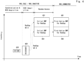
- Fig. 4 is a conceptual diagram illustrating BWP transitions or switching for RedCap UEs.
- two RedCap-specific initial BWPs 431 and 432 are configured in the cell 10.
- the RedCap-specific initial BWP 431 includes a pair of an initial DL BWP and an initial UL BWP with the same center frequency.
- the bandwidth of the initial DL BWP may be the same as or different from the bandwidth of the initial UL BWP.
- the RedCap-specific initial BWP 432 includes a pair of an initial DL BWP and an initial UL BWP with the same center frequency.
- the bandwidth of the initial DL BWP may be the same as or different from the bandwidth of the initial UL BWP.
- RedCap UEs in RRC_IDLE or RRC_INACTIVE decode the MIB in a CD-SSB 410 and obtain a configuration of a CORESET#0 420 from the MIB.
- the RedCap UEs then perform blind decoding to find a DCI/PDCCH for SIB1 reception in the CORESET#0 420. If the blind decoding is successful, the RedCap UEs receive a PDSCH carrying the SIB1.
- the RedCap UEs then obtain a configuration of the two RedCap-specific initial BWPs 431 and 432 from the SIB1.
- the RedCap UEs then select one of the two RedCap-specific initial BWPs 431 and 432. Some RedCap UEs (e.g., RedCap UE A) select the initial BWP 431, while other RedCap UEs (e.g., RedCap UE A) select the initial BWP 432. The RedCap UEs re-tune their respective RF components to the center frequency of the selected initial BWP and perform random or initial access to the cell 10 at the selected initial BWP.
- each RedCap UE receives an RRC message (e.g., RRC Setup or RRC Resume) from the RAN node 1 indicating a UE dedicated BWP configuration.
- the UE dedicated BWP configuration includes a configuration of a first active BWP (first active DL BWP and first active UL BWP).
- the first active BWP is a BWP that the UE shall use from the time when (or immediately after) the RRC connection establishment is completed in the serving cell.
- Each RedCap UE applies the UE dedicated BWP configuration and transitions to RRC_CONNECTED at the configured first active BWP.
- a RedCap UE with a successful random access in the initial BWP 431 uses a first active BWP 441, while a RedCap UE with a successful random access in the initial BWP 432 uses a first active BWP 442.
- the first active BWP 441 has the same center frequency and bandwidth as the initial BWP 431, and similarly, the first active BWP 442 has the same center frequency and bandwidth as the initial BWP 432. This allows a RedCap UEs to continue to use the initial BWP as the first active BWP without re-tuning its RF components.
- this is only an example.
- One or both of the center frequency and bandwidth of the first active BWP 441 may be different from those of the initial BWP 431.
- one or both of the center frequency and bandwidth of the first active BWP 442 may be different from those of the initial BWP 432.
- the BWP configuration shown in Fig. 4 can be modified as follows.
- the RedCap UE specific initial BWPs 431 and 432 may have different bandwidths from each other.
- One of the RedCap UE specific initial BWPs 431 and 432 may be configured to contain the CD-SSB 410 and the CORESET#0 420.
- An example configuration of a radio communication system according to this example embodiment may be the same as the example shown in Fig. 1 .
- This example embodiment provides various specific examples of initial BWP selection by RedCap UEs.
- the initial BWP selection as described in this example embodiment may be applied to the first example embodiment, specifically to step 202 in Fig. 2 .
- the UE 2 may select one initial DL BWP and one initial UL BWP to be used for random access from a plurality of initial DL BWPs and a plurality of initial UL BWPs that are specific to RedCap UEs as follows. In other words, the UE 2 may select a pair from a plurality of pairs of initial DL and DL BWPs as follows.
- the UE 2 may randomly select the one initial DL BWP and the one initial UL BWP.
- the UE 2 may select the one initial DL BWP and the one initial UL BWP based on a UE identifier of the UE 2.
- the UE identifier may be part or all of, for example, a Subscription Permanent Identifier (SUPI).
- SUPI Subscription Permanent Identifier
- the UE 2 may select the one initial DL BWP and the one initial UL BWP based on a group identifier assigned by a core network (e.g., 5GC).
- a core network e.g., 5GC
- the group identifier assigned by the core network may be a Paging Subgroup ID assigned by an Access and Mobility Management Function (AMF).
- AMF Access and Mobility Management Function
- the UE 2 may select the one initial DL BWP and the one initial UL BWP based on a measured value of received power or received quality of a downlink signal.
- the received power measurement value may be a measured value of Reference Signal Received Power (RSRP) of a resource within the CD-SSB.
- the received quality measurement value may be a measured value of Reference Signal Received Quality (RSRQ) of a resource within the CD-SSB.
- the UE 2 may select the initial DL BWP and the initial UL BWP (e.g., initial BWP 432 in Fig. 4 ) that are closest to the CD-SSB (e.g., CD-SSB 410 in Fig. 4 ) in the frequency domain to use for random access.
- the measured value equals or exceeds the first threshold value, it means that the reception quality of the CD-SSB is relatively good. Accordingly, it can be expected that better communication quality can be achieved in random access between the RAN node 1 and the UE 2 by selecting the initial DL BWP and the initial UL BWP whose frequency location is closer to the CD-SSB.
- the UE 2 may select the initial DL BWP and the initial UL BWP (e.g., initial BWP 431 in Fig. 4 ) that are farthest from the CD-SSB (e.g., CD-SSB 410 in Fig. 4 ) in the frequency domain to use for random access. If the measured value is below the second threshold value, it means that the reception quality of the CD-SSB is relatively poor.
- the initial DL BWP and the initial UL BWP e.g., initial BWP 431 in Fig. 4
- the CD-SSB e.g., CD-SSB 410 in Fig. 4
- the second threshold value can be configured to be lower than the first threshold value. In this case, if the measured value is between the first threshold value and the second threshold value, the UE 2 may randomly select the initial DL BWP and the initial UL BWP to be used for random access.
- the first threshold value or the first and second threshold values may be broadcast in the cell 10 by the network (e.g., RAN node 1).
- the first threshold value or the first and second threshold values may be included in SIB1.
- the UE 2 uses the received power or received quality of a resource within each of a plurality of Non-Cell Defining (NCD) SSBs, each of which is contained in a respective one of the plurality of initial DL BWPs.
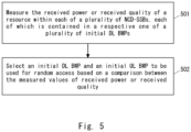
- Fig. 5 shows an example of the operation of the UE 2 in the fifth example.
- the UE 2 measures the received power or received quality of a resource within each of a plurality of NCD-SSBs, each of which is contained in a respective one of the plurality of initial DL BWPs.
- the UE 2 selects the initial DL BWP and the initial UL BWP to be used for random access based on a comparison between the measured values of received power or received quality.
- NCD-SSBs are not associated with RMSIs (or SIB1).
- Downlink signals that are available for downlink power or quality measurements such as a PBCH demodulation reference signal (DMRS), are transmitted in the resources within the NCD-SSBs.
- DMRS PBCH demodulation reference signal
- the UE 2 may select a pair of an initial DL BWP having the best measured values of received power or received quality of a resource within the NCD-SSB and its corresponding initial UL BWP, and use them for random access. This is expected to improve the communication quality in random access between the RAN node 1 and the UE 2.
- the UE 2 may select any pair of an initial DL BWP for which the received power or received quality measured value of a resource within the NCD-SSB exceeds the threshold value, and its corresponding initial UL BWP. If multiple pairs of BWPs exceed the threshold, the UE 2 may select any of these multiple pairs of BWPs. Such a selection operation can also help to improve the communication quality of random access between the RAN node 1 and the UE 2.
- the UE 2 needs to obtain configuration information for the NCD-SSBs contained in the RedCap-specific initial DL BWPs.
- the RAN node 1 may provide the NCD-SSB configuration information to the UE 2 via SIB1.
- SIB1 may contain the configuration information for the NCD-SSBs contained in the RedCap-specific initial DL BWPs.
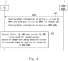
- Fig. 6 shows an example of signaling between the RAN node 1 and the UE 2 with respect to the fifth example.
- the RAN node 1 transmits SIB1 to UE 2.
- the RAN node 1 broadcasts SIB1 in the cell 10, and the UE 2 receives the SIB1.
- the SIB1 contains configuration information for a plurality of (second) initial DL BWPs and a plurality of (second) initial UL BWPs that are specific or dedicated to RedCap UEs.
- the SIB1 also contains configuration information for a plurality of NCD-SSBs, each of which is contained in a respective one of the RedCap-specific initial DL BWPs.
- step 602 the UE2 compares measured values of received power or quality on resources within the NCD-SSBs. Based on this comparison, the UE2 then selects an initial DL BWP and an initial UL BWP to be used for random access (or initial access).
- Fig. 7 shows an example of the message structure or format of SIB1 sent in step 601.
- SIB1 700 has the same basic structure as the SIB1 300 shown in Fig. 3 .
- the fields or IEs 710, 720, 721, 722, 723, 730, 731, 732, and 733 shown in Fig. 7 correspond to or are similar to the fields or IEs 310, 320, 321, 322, 323, 330, 331, 332, and 333 shown in Fig. 3 , respectively.
- the InitialDownlinkBWP-RedCap field 723 includes an InitialDownlinkBWPList-RedCap field 724 that is similar to the InitialDownlinkBWPList-RedCap field 323 in Fig. 3 .
- the InitialDownlinkBWP-RedCap field 723 includes a NonCellDefiningSSBList field 725.
- the NonCellDefiningSSBList field 725 is used to configure common parameters of one or more initial DL BWPs that are specific or dedicated to RedCap UEs. These parameters are "cell specific".
- the NonCellDefiningSSBList field 725 is a list of one or more NonCellDefiningSSB IEs.
- the maximum number of initial DL BWPs for RedCap that can be configured in the cell 10 (maxNrofinitialDownlinkBWP-RedCap) may be specified in the 3GPP specification.
- the NonCellDefiningSSB IE indicates a configuration of one or more NCD-SSBs contained in the one or more RedCap-specific initial DL BWPs specified in the InitialDownlinkBWPList-RedCap field 323.
- Fig. 8 is a block diagram showing an example configuration of the RAN node 1 according to the above example embodiments.
- the RAN node 1 includes a radio frequency (RF) transceiver 801, a network interface 803, a processor 804, and a memory 805.
- the RF transceiver 801 performs analog RF signal processing to communicate with UEs.
- the RF transceiver 801 may include a plurality of transceivers.
- the RF transceiver 801 is coupled to an antenna array 802 and the processor 804.
- the RF transceiver 801 receives modulated symbol data from the processor 804, generates a transmit RF signal, and supplies the transmit RF signal to the antenna array 802.
- the RF transceiver 801 generates a baseband receive signal based on a received RF signal received by the antenna array 802 and provides it to the processor 804.
- the RF transceiver 801 may include analog beamformer circuitry for beamforming.
- the analog beamformer circuitry includes a plurality of phase shifters and a plurality of power amplifiers.
- the network interface 803 is used to communicate with network nodes (e.g., other RAN nodes, and control plane and user plane nodes in the core network).
- the network interface 803 may include an IEEE 802.3 series compliant network interface card (NIC).
- NIC network interface card
- the processor 804 performs digital baseband signal processing (data-plane processing) and control-plane processing for wireless communication.
- the processor 804 may include a plurality of processors.
- the processor 804 may include a modem processor (e.g., Digital Signal Processor (DSP)) for performing the digital baseband signal processing and a protocol stack processor (e.g., Central Processing Unit (CPU) or Micro Processing Unit (MPU)) for performing the control-plane processing.
- DSP Digital Signal Processor
- MPU Micro Processing Unit
- the digital baseband signal processing by the processor 804 may include signal processing of the Service Data Adaptation Protocol (SDAP) layer, Packet Data Convergence Protocol (PDCP) layer, Radio Link Control (RLC) layer, Medium Access Control (MAC) layer, and Physical (PHY) layer.
- SDAP Service Data Adaptation Protocol
- PDCP Packet Data Convergence Protocol
- RLC Radio Link Control
- MAC Medium Access Control
- PHY Physical
- the control plane processing by the processor 804 may include processing of Non-Access Stratum (NAS) messages, RRC messages, Medium Access Control (MAC) Control Elements (CEs), and Downlink Control Information (DCI).
- NAS Non-Access Stratum
- MAC Medium Access Control
- CEs Medium Access Control Elements
- DCI Downlink Control Information
- the control plane processing by the processor 804 may further include processing of application layer signaling protocols such as XnAP, F1AP, NGAP, etc.
- the processor 804 may include a digital beamformer module for beamforming.
- the digital beamformer module may include a Multiple Input Multiple Output (MIMO) encoder and precoder.
- MIMO Multiple Input Multiple Output
- the memory 805 consists of a combination of volatile and non-volatile memory.
- the volatile memory is, for example, a Static Random Access Memory (SRAM), a Dynamic RAM (DRAM), or a combination thereof.
- the non-volatile memory may be a Mask Read Only Memory (MROM), an Electrically Erasable Programmable ROM (EEPROM), a flash memory, or a hard disk drive, or any combination thereof.
- the memory 805 may include storage remote from the processor 804. In this case, the processor 804 may access the memory 805 through the network interface 803 or any I/O interface.
- the memory 805 may store one or more software modules (computer programs) 806 containing a set of instructions and data for processing by the RAN node 1 described in the example embodiments described above.
- the processor 804 may be configured to read and execute the software module(s) 806 from the memory 805, thereby performing the processing of the RAN node 1 described in the example embodiments described above.
- the RAN node 1 is a Central Unit (CU) (e.g., eNB-CU or gNB-CU) or a CU-CP, the RAN node 1 does not necessarily include the RF transceiver 801 (and the antenna array 802).
- CU Central Unit
- the RAN node 1 does not necessarily include the RF transceiver 801 (and the antenna array 802).
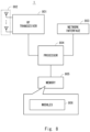
- Fig. 9 shows a block diagram of an example configuration of the UE 2.
- the RF transceiver performs analog RF signal processing to communicate with the RAN node 2.
- the RF transceiver 901 may include a plurality of transceivers.
- the analog RF signal processing performed by the RF transceiver 901 includes frequency up-conversion, frequency down-conversion, and amplification.
- the RF transceiver 901 is coupled to an antenna array 902 and a baseband processor 903.
- the RF transceiver 901 receives modulated symbol data (or OFDM symbol data) from the baseband processor 903, generates a transmit RF signal, and provides the transmit RF signal to the antenna array 902.
- the RF transceiver 901 generates a baseband received signal based on a received RF signal received by the antenna array 902, and provides it to the baseband processor 903.
- the RF transceiver 901 may include analog beamformer circuitry for beamforming.
- the analog beamformer circuitry includes a plurality of phase shifters and a plurality of power amplifiers.
- the baseband processor 903 performs digital baseband signal processing (data-plane processing) and control-plane processing for wireless communication.
- the digital baseband signal processing includes (a) data compression/decompression, (b) data segmentation/concatenation, (c) transmission format (transmission frame) composition/decomposition, (d) channel encoding/decoding, (e) modulation (i.e., symbol mapping)/demodulation, and (f) Inverse Fast Fourier Transform (IFFT) generation of OFDM symbol data (baseband OFDM signal).
- IFFT Inverse Fast Fourier Transform
- control-plane processing includes communication management of layer 1 (e.g., transmission power control), layer 2 (e.g., radio resource management, and hybrid automatic repeat request (HARQ) processing), and layer 3 (e.g., signaling regarding attach, mobility, and call management).
- layer 1 e.g., transmission power control
- layer 2 e.g., radio resource management, and hybrid automatic repeat request (HARQ) processing
- layer 3 e.g., signaling regarding attach, mobility, and call management.
- the digital baseband signal processing by the baseband processor 903 may include signal processing of the SDAP layer, PDCP layer, RLC layer, MAC layer, and PHY layer.
- the Control plane processing by the baseband processor 903 may include processing of Non-Access Stratum (NAS) protocols, RRC protocols, MAC CEs, and DCIs.
- NAS Non-Access Stratum
- the baseband processor 903 may perform MIMO encoding and precoding for beamforming.
- the baseband processor 903 may include a modem processor (e.g., DSP) for digital baseband signal processing and a protocol stack processor (e.g., CPU or MPU) for control-plane processing.
- a modem processor e.g., DSP
- a protocol stack processor e.g., CPU or MPU
- the protocol stack processor performing control plane processing may be integrated with an application processor 904 described below.
- the application processor 904 may also be referred to as a CPU, an MPU, a microprocessor, or a processor core.
- the application processor 904 may include a plurality of processors (processor cores).
- the application processor 904 executes a system software program (operating system (OS)) and various application programs (e.g., call application, web browser, mailer, camera control application, music player application) read from the memory 906 or a memory not shown in the figure, thereby providing various functions of the UE 2.
- OS operating system
- application programs e.g., call application, web browser, mailer, camera control application, music player application
- the baseband processor 903 and the application processor 904 may be integrated on a single chip.
- the baseband processor 903 and the application processor 904 may be implemented in a single System on Chip (SoC) device 905.
- SoC System on Chip
- a SoC device may be referred to as a system Large Scale Integration (LSI) or a chipset.
- the memory 906 is a volatile memory or a non-volatile memory, or a combination thereof.
- the memory 906 may include a plurality of physically independent memory devices.
- the volatile memory is, for example, Static Random Access Memory (SRAM), Dynamic RAM (DRAM), or a combination thereof.
- the non-volatile memory may be a Mask Read Only Memory (MROM), an Electrically Erasable Programmable ROM (EEPROM), a flash memory, a hard disk drive, or any combination thereof.
- the memory 906 may include, for example, an external memory device that can be accessed by the baseband processor 903, the application processor 904, or the SoC 905.
- the memory 906 may include an internal memory device that is integrated into the baseband processor 903, the application processor 904, or the SoC 905. Further, the memory 906 may include a memory in a Universal Integrated Circuit Card (UICC).
- UICC Universal Integrated Circuit Card
- the memory 906 may store one or more software modules (computer programs) 907 including instructions and data for processing by the UE 2 described in the above example embodiments.
- the baseband processor 903 or the application processor 904 may read and execute the software module(s) 907 from the memory 906, thereby performing the processing of the UE 2 described in the above example embodiments with reference to the drawings.
- control-plane processing and operations performed by the UE 2 described in the above example embodiments can be achieved by elements other than the RF transceiver 901 and the antenna array 902, i.e., achieved by the memory 906, which stores the software module(s) 907, and one or both of the baseband processor 903 and the application processor 904.
- each of the processors of the RAN node 1 and the UE 2 in the example embodiments described above can execute one or more programs, including a set of instructions, to cause a computer to perform an algorithm described with reference to the drawings.
- Each of these programs contains a set of instructions (or software code) that, when loaded into a computer, causes the computer to perform one or more of the functions described in the example embodiments.
- Each of these programs may be stored in a non-transitory computer readable medium or a tangible storage medium.
- non-transitory computer readable media or tangible storage media can include a random-access memory (RAM), a read-only memory (ROM), a flash memory, a solid-state drive (SSD) or other memory technologies, CD-ROM, digital versatile disk (DVD), Blu-ray (registered mark) disc or other optical disk storage, magnetic cassettes, magnetic tape, magnetic disk storage or other magnetic storage devices.
- RAM random-access memory
- ROM read-only memory
- flash memory a solid-state drive
- SSD solid-state drive
- CD-ROM compact disc
- DVD digital versatile disk
- Blu-ray registered mark
- Each program may be transmitted on a transitory computer readable medium or a communication medium.
- transitory computer readable media or communication media can include electrical, optical, acoustical, or other form of propagated signals.
- Supplementary Notes For example, the whole or part of the example embodiments disclosed above can be described as, but not limited to, the following Supplementary Notes.
- some or all of the elements (e.g., configurations and functionalities) described in the Supplementary Notes directed to apparatus (e.g., UE and RAN nodes) may also be described as supplementary notes directed to methods and programs.
- some or all of the elements described in Supplementary Notes 2-14 that depend on Supplementary Note 1 may also be written as Supplementary Notes that depend on Supplementary Notes 15 and 16 with the same dependency relationship as Supplementary Notes 2-14.
- Some or all of the elements described in each Supplementary Note may be applicable to various hardware, software, storage for storing software, systems, and methods.
- a User Equipment comprising:
- the at least one processor is configured to select the one initial DL BWP and the one initial UL BWP based on a measured value of received power or received quality of a downlink signal.
- the at least one processor is configured to select a pair of an initial DL BWP having a best measured value of received power or received quality of the resource in the NCD-SSB and a corresponding initial UL BWP as the one initial DL BWP and the one initial UL BWP, respectively.
- the at least one processor is configured to select a pair of an initial DL BWP for which a measured value of received power or received quality of the resource in the NCD-SSB exceeds a threshold value and a corresponding initial UL BWP as the one initial DL BWP and the one initial UL BWP, respectively.
- the UE according to any one of Supplementary Notes 1 to 13, wherein the particular type of UE is a Reduced Capability (RedCap) UE.
- RedCap Reduced Capability
- a radio access network (RAN) node comprising:
- the RAN node according to Supplementary Note 17, wherein the configuration information causes the particular type of UE to select, from the plurality of initial DL BWPs and the plurality of initial UL BWPs, one initial DL BWP and one initial UL BWP to be used for random access.
- the RAN node according to Supplementary Note 18, wherein the configuration information causes the particular type of UE to randomly select the one initial DL BWP and the one initial UL BWP.
- the RAN node according to Supplementary Note 18, wherein the configuration information causes the particular type of UE to select the one initial DL BWP and the one initial UL BWP based on a UE identifier.
- the RAN node according to Supplementary Note 18, wherein the configuration information causes the particular type of UE to select the one initial DL BWP and the one initial UL BWP based on a group identifier assigned by a core network.
- the RAN node according to Supplementary Note 18, wherein the configuration information causes the particular type of UE to select the one initial DL BWP and the one initial UL BWP based on a measured value of received power or received quality of a downlink signal.
- the configuration information causes the particular type of UE to select a pair of an initial DL BWP having a best measured value of received power or received quality of the resource in the NCD-SSB and a corresponding initial UL BWP as the one initial DL BWP and the one initial UL BWP, respectively.
- the configuration information causes the particular type of UE to select a pair of an initial DL BWP for which a measured value of received power or received quality of the resource in the NCD-SSB exceeds a threshold value and a corresponding initial UL BWP as the one initial DL BWP and the one initial UL BWP, respectively.
- the RAN node according to any one of Supplementary Notes 27 to 29, wherein the SIB1 contains configuration information for the plurality of NCD-SSBs.
- the RAN node according to any one of Supplementary Notes 17 to 30, wherein the particular type of UE is a Reduced Capability (RedCap) UE.
- RedCap Reduced Capability
- a method performed by a radio access network (RAN) node comprising: transmitting a System Information Block Type 1 (SIB1) containing configuration information for a plurality of initial downlink (DL) bandwidth parts (BWPs) and a plurality of initial uplink (UL) BWPs specific to a particular type of User Equipment (UE).
- SIB1 System Information Block Type 1
- SIB1 System Information Block Type 1
Landscapes
- Engineering & Computer Science (AREA)
- Computer Networks & Wireless Communication (AREA)
- Signal Processing (AREA)
- Computer Security & Cryptography (AREA)
- Mobile Radio Communication Systems (AREA)
Abstract
Description
- The present disclosure relates to radio communication systems, and in particular to signaling between a radio access network node and a user equipment (UE).
- 3rd Generation Partnership Project (3GPP (registered trademark)) Release 17 supports Reduced Capability (RedCap) UEs (see, for example, section 16.13 of Non-Patent Literature 1). A RedCap UE has reduced capabilities with the intention to have lower complexity with respect to non-RedCap UEs. It is mandatory for a RedCap UE to support 20 MHz maximum UE channel bandwidth in FR1 (i.e., sub-6 GHz band) and 100 MHz in FR2 (i.e., millimeter wave (mmWave) band). On the other hand, functions related to Carrier Aggregation (CA), Multi-Radio Dual Connectivity (MR-DC), Dual Active Protocol Stack (DAPS), and Integrated Access and Backhaul (IAB) are not supported by RedCap UEs.
- For example, for RedCap UEs, the minimum number of UE Reception (Rx) branches and the maximum number of Downlink (DL) Multiple Input Multiple Output (MIMO) layers are reduced or relaxed compared to those for non-RedCap UEs. In FR1, one DL MIMO layer is supported if one Rx branch is supported, and two DL MIMO layers are supported if two Rx branches are supported. In FR2, one or two DL MIMO layers can be supported, and two Rx branches are always supported. In FR1 and FR2, the UE functions and corresponding capabilities for more than two UE Rx branches or more than two DL MIMO layers, and the UE functions and capabilities for more than two UE Tx branches or more than two Uplink (UL) MIMO layers are not supported by RedCap UEs.
- RedCap UEs in Radio Resource Control (RRC)_IDLE and RRC_INACTIVE monitor paging only in the (default or RedCap-specific) initial DL Bandwidth Part (BWP) associated with the Cell Defining (CD) Synchronization Signal (SS)/Physical Broadcast Channel (PBCH) block (SSB) and perform cell (re)selection and measurements in the CD-SSB. When the RedCap-specific initial UL BWP is configured, RedCap UEs in RRC_IDLE and RRC_INACTIVE need only use the RedCap-specific initial UL BWP to perform random access (Random Access Channel (RACH)).
- Non-Patent
Literature 2 specifies extensions for RedCap UEs in RRC messages. System Information Block Type 1 (SIB1) includes the initial DL BWP and initial UL BWP configurations for non-RedCap UEs, and may additionally include the initial DL BWP and initial UL BWP configurations specific or dedicated to RedCap UEs. - The RedCap-specific initial UL BWP configurations are specified in the initialUplinkBWP-RedCap-r17 field or information element (IE) in the UplinkConfigCommonSIB within the ServingCellConfigCommonSIB of SIB1. The initialUplinkBWP-RedCap-r17 field or information element (IE) is a BWP-UplinkCommon IE. The BWP-UplinkCommon IE contains a rach-ConfigCommon field or IE. The rach-ConfigCommon field or IE indicates a configuration of cell-specific random access parameters used by UEs, i.e., RedCap UEs, for contention-based and contention-free random access in the BWP.
- On the other hand, the RedCap-specific initial DL BWP configurations are specified in the initialDownlinkBWP-RedCap-r17 field or IE in the DownlinkConfigCommonSIB in the ServingCellConfigCommonSIB in SIB1. The initialDownlinkBWP-RedCap-r17 field or IE is a BWP-DownlinkCommon IE. The BWP-DownlinkCommon IE contains a pdcch-ConfigCommon field or IE. The pdcch-ConfigCommon field or IE can specify a Type-1 common search space using a ra-SearchSpace field or IE. Specifically, the pdcch-ConfigCommon field or IE contains a commonSearchSpaceList field or IE that specifies one or more common search spaces (CSSs) within the BWP. The commonSearchSpaceList field or IE is a list of up to four SearchSpace IEs. Each SearchSpace IE specifies a SearchSpaceId and defines the method and location for searching for Physical Downlink Control Channel (PDCCH) candidates.
- In other words, the RedCap-specific initial DL BWP can be configured with a Type-1 common search space to receive a PDCCH carrying Downlink Control Information (DCI) for a random access message 2 (MSG2), message B (MSGB), and message 4 (MSG4), i.e., a Physical Downlink Shared Channel (PDSCH). A RedCap UE searches in the Type-1 common search space configured in the RedCap-specific initial DL BWP to receive a DCI/PDCCH indicating a PDSCH carrying MSG2, MSGB, or MSG4, and receives MSG2, MSGB, or MSG4 based on the received DCI.
-
Section 1 of Non-Patent Literature 3 states that at a previous 3GPP Technical Specification Group Radio Access Network (TSG-RAN) Working Group 1 (WG1) (RAN1) meeting, it was agreed that several options would be further investigated to ensure that a Random Access Channel (RACH) occasion associated with the best SSB falls within the RedCap UE bandwidth. One of these options (i.e., Option 2) is one or more separate initial UL BWPs for RedCap UEs. - Section 2.1 of Non-Patent Literature 3 proposes multiple initial DL BWPs for RedCap UEs (
Proposal 2 andFigure 1 of Non-Patent Literature 2). Multiple initial DL BWPs are used for initial access (or random access), specifically for sending Random Access Response (RAR) and paging during initial access. Of these multiple initial DL BWPs, one is the initial DL BWP configured by the Master Information Block (MIB). The others may be "copies" of the initial DL BWP configured by the MIB, and may use, for example, the same Control Resource Set (CORESET) #0, the same PDCCH search space, the same bandwidth, and the same subcarrier spacing. Only the center frequencies of these initial DL BWPs need to be configured. Different RedCap UEs can be placed in different initial DL BWPs for random access and paging reception. - In addition, Section 2.2 of Non-Patent Literature 3 describes multiple initial UL BWPs for RedCap UEs. Specifically, this presents a case where multiple initial UL BWPs are configured in conjunction with a single initial DL BWP (
Figure 3 of Non-Patent Literature 3). In this case, it is stated that a RedCap UE determines one of the multiple initial UL BWPs based on the selected random access occasion (RO). -
- [Non-Patent Literature 1] 3GPP TS 38.300 V17.1.0 (2022-06), 3rd Generation Partnership Project; Technical Specification Group Radio Access Network; NR; NR and NG-RAN Overall Description; Stage 2 (Release 17), July 2022
- [Non-Patent Literature 2] 3GPP TS 38.331 V17.1.0 (2022-06), 3rd Generation Partnership Project; Technical Specification Group Radio Access Network; NR; Radio Resource Control (RRC) protocol specification (Release 17), July 2022
- [Non-Patent Literature 3] OPPO, "Discussion on reduced UE bandwidth", R1-2102402, 3GPP TSG-RAN WG1 Meeting #104b-e, April 12-20, 2021
- Non-Patent Literature 3 does not clearly describe how to configure multiple initial DL BWPs and multiple initial UL BWPs specific or dedicated to RedCap, or in other words, how the network notifies RedCap UEs of them.
- One of the objectives to be achieved by the example embodiments disclosed herein is to provide apparatus, methods, and programs that contribute to providing specific methods for notifying a particular type of UE (e.g., RedCap UEs) of multiple initial DL BWPs and multiple initial UL BWPs that are specific to or dedicated to that particular type of UE. It should be noted that this object is only one of the objects to be achieved by the example embodiments disclosed herein. Other objects or problems and novel features will become apparent from the following description and the accompanying drawings.
- In a first aspect, a UE includes at least one memory and at least one processor coupled to the at least one memory. The at least one processor is configured to receive a SIB1 containing configuration information for a plurality of initial DL BWPs and a plurality of initial UL BWPs specific to a particular type of UE. The at least one processor is configured to select, from the plurality of initial DL BWPs and the plurality of initial UL BWPs, one initial DL BWP and one initial UL BWP to be used for random access.
- In a second aspect, a method performed by a UE includes the steps of:
- (a) receiving a SIB1 containing configuration information for a plurality of initial DL BWPs and a plurality of initial UL BWPs specific to a particular type of UE; and
- (b) selecting, from the plurality of initial DL BWPs and the plurality of initial UL BWPs, one initial DL BWP and one initial UL BWP to be used for random access.
- In a third aspect a first RAN node includes at least one memory and at least one processor coupled to the at least one memory. The at least one processor is configured to transmit a SIB1 containing configuration information for a plurality of initial DL BWPs and a plurality of initial UL BWPs specific to a particular type of UE.
- In a fourth aspect, a method performed by a first type RAN node includes transmitting a SIB1 containing configuration information for a plurality of initial DL BWPs and a plurality of initial UL BWPs specific to a particular type of UE.
- According to the aspects described above, it is possible to provide apparatus, methods, and programs that contribute to providing specific methods for notifying a particular type of UE (e.g., RedCap UEs) of multiple initial DL BWPs and multiple initial UL BWPs that are specific to or dedicated to that particular type of UE.
-
-
Fig. 1 shows an example configuration of a radio communication system with respect to one or more example embodiments; -
Fig. 2 is a sequence diagram showing an example of signaling between a RAN node and a UE with respect to one or more example embodiments; -
Fig. 3 shows an example of the message structure or format of SIB1 with respect to one or more example embodiments; -
Fig. 4 is a conceptual diagram explaining BWP transitions with respect to one or more example embodiments; -
Fig. 5 is a flowchart showing an example of the operation of a UE with respect to one or more example embodiments; -
Fig. 6 is a sequence diagram showing an example of signaling between a RAN node and a UE with respect to one or more example embodiments; -
Fig. 7 shows an example of the message structure or format of SIB1 with respect to one or more example embodiments; -
Fig. 8 is a block diagram showing an example configuration of a RAN node with respect to one or more example embodiments; and -
Fig. 9 is a block diagram showing an example configuration of a UE with respect to one or more example embodiments. - Specific example embodiments will be described hereinafter in detail with reference to the drawings. Identical or corresponding elements are designated by the same symbols throughout the drawings, and duplicate explanations are omitted where necessary for the sake of clarity.
- The multiple example embodiments described below may be implemented independently or in any combination of two or more, as appropriate. These multiple example embodiments have novel features that differ from one another. Accordingly, these multiple example embodiments contribute to achieving different objectives or solving different problems and contribute to achieving different advantages.
- Each of the drawings or figures is merely an example to illustrate one or more example embodiments. Each figure may not be associated with only one particular example embodiment, but may be associated with one or more other example embodiments. As will be appreciated by those of ordinary skill in the art, various features or steps described with respect to any one of the figures may be combined with features or steps illustrated in one or more other figures to produce, for example, example embodiments that are not explicitly illustrated or described. Not all of the features or steps illustrated in any one of the figures to describe an example embodiment are necessarily essential, and some features or steps may be omitted. The order of the steps described in any of the figures may be changed as appropriate.
- The following example embodiments are described primarily with respect to the 3GPP Long Term Evolution (LTE) system and the 5th generation mobile communication system (5G system). However, these example embodiments can be applied to other radio communication systems supporting technologies similar to the 3GPP systems. The term LTE as used herein includes improvements and enhancements to LTE and LTE-Advanced to enable interworking with 5G systems, unless otherwise specified.
- As used in this specification, "if" can be interpreted to mean "when", "at or around the time", "after", "upon", "in response to determining", "in accordance with a determination", or "in response to detecting", depending on the context. These expressions can be interpreted to mean the same thing, depending on the context. As used in this specification, "in response to" may be paraphrased as "based on", depending on the context.
- First, the configuration and operation of a plurality of network elements common to a plurality of example embodiments are described.
Fig. 1 shows an example configuration of a radio communication system related to a plurality of example embodiments. In the example ofFig. 1 , the radio communication system includes a Radio Access Network (RAN)node 1 and one ormore UEs 2. Each element (or network function) shown inFig. 1 may be implemented, for example, as a network element on dedicated hardware, as a software instance running on dedicated hardware, or as a virtualized function instantiated on an application platform. - The
RAN node 1 is deployed in a RAN. TheRAN node 1 may be an NG-RAN node, specifically a gNB or ng-eNB. An ng-eNB is a node that provides E-UTRA user plane and control plane protocol termination to a UE and is connected to a 5G Core Network (5GC) via NG interfaces. TheRAN node 1 may be a combination of a Central Unit (CU) (e.g., gNB-CU or eNB-CU) and one or more Distributed Units (DUs) (e.g., gNB-DUs or eNB-DUs) in a cloud RAN (C-RAN) deployment. - The
RAN node 1 serves acell 10 to multiple types ofUEs 2. These multiple types ofUEs 2 use thecell 10 as their serving cell and perform Contention Based Random Access (CBRA) in thecell 10. TheRAN node 1 may further serve one or more other cells. In this case, thecell 10 may be a primary cell (PCell) in Carrier Aggregation (CA), and one or more other cells may be secondary cells (SCells). That is, thecell 10 is a cell in whichUEs 2 in RRC_IDLE initiate an RRC connection establishment procedure. UEs 2 in RRC_INACTIVE may initiate an RRC connection resume procedure in thecell 10. UEs 2 in RRC_CONNECTED may initiate an RRC connection re-establishment procedure in thecell 10. - The
RAN node 1 broadcasts the Minimum SI (i.e., MIB and SIB1) in thecell 10. TheRAN node 1 may also transmit other SI. The Other SI contains all SIBs that are not always broadcast within the Minimum SI. These SIBs are broadcast periodically on a DL Shared Channel (DL-SCH), broadcast on demand on a DL-SCH (i.e., upon request from UEs in RRC_IDLE or RRC_INACTIVE), or sent in a dedicated manner on a DL_SCH to UEs in RRC_CONNECTED. - The
UEs 2 may be referred to by other names such as radio terminals, mobile terminals, mobile stations, or wireless transmit receive units (WTRUs). TheUEs 2 may be implemented in machines, vehicles, or devices. By way of example, but not limitation, theUEs 2 may be implemented in machines, vehicles, or devices with mobility, and in particular in automated guided vehicles (AGVs), mobile robots, construction machines, or unmanned or uncrewed aerial vehicles (UAVs). - Each
UE 2 performs cell selection or cell reselection when it is in RRC_IDLE or RRC_INACTIVE. In addition, eachUE 2 may perform RRC connection re-establishment when it is in RRC_CONNECTED state. EachUE 2 receives MIB and SIB1 in thecell 10 and configures the initial DL BWP and initial UL BWP based on cell-specific common parameters for the initial DL BWP and initial UL BWP in thecell 10 contained in SIB1. EachUE 2 then uses the Initial DL BWP and Initial UL BWP to perform a random access procedure in thecell 10 and initiate an RRC connection establishment, resume, or re-establishment procedure. - The
UEs 2 are divided into first type and second type. Second type UEs are UEs with limited capabilities compared to first type UEs. The second type of UE may have limited RF capability compared to the first type of UE. The second type of UE may be a RedCap UE. In contrast, the first type of UE may be referred to as a normal UE or a non-RedCap UE. In the following description, the second type of UE is considered to be a RedCap UE and the first type of UE is considered to be a Normal UE or a Non-RedCap UE. - As described previously, a RedCap UE has reduced capabilities with the intention to have lower complexity with respect to non-RedCap UEs. In the current 3GPP specification, it is mandatory for a RedCap UE to support 20 MHz maximum UE channel bandwidth in FR1 (i.e., sub-6 GHz band) and 100 MHz in FR2 (i.e., millimeter wave (mmWave) band). On the other hand, functions related to CA, MR-DC, DAPS, and IAB are not supported by RedCap UEs.
- For example, for RedCap UEs, the minimum number of UE Rx branches and the maximum number of DL MIMO layers are reduced or relaxed compared to those for non-RedCap UEs. In FR1, one DL MIMO layer is supported if one Rx branch is supported, and two DL MIMO layers are supported if two Rx branches are supported. In FR2, one or two DL MIMO layers can be supported, and two Rx branches are always supported. In FR1 and FR2, the UE functions and corresponding capabilities for more than two UE Rx branches or more than two DL MIMO layers, and the UE functions and capabilities for more than two UE Tx branches or more than two UL MIMO layers are not supported by RedCap UEs. RedCap UEs may support time division duplex (TDD) or half-duplex frequency division duplex (HD-FDD). For HD-FDD, RedCap UEs can share an antenna and radio frequency (RF) components for uplink transmission and downlink reception.
- RedCap UEs in RRC_IDLE and RRC_INACTIVE monitor paging only in the (default or RedCap-specific) initial DL BWP associated with the CD-SSB and perform cell (re)selection and measurements in the CD-SSB. If the initial UL BWP is configured for RedCap, RedCap-specific, or RedCap-dedicated, RedCap UEs in RRC_IDLE and RRC_INACTIVE use only the RedCap-specific initial UL BWP to perform random access (or RACH).
- The initial DL BWP for RedCap, specific to RedCap, or dedicated to RedCap, can be configured with a Type-1 common search space to receive a PDCCH carrying a DCI for a random access MSG2, MSGB, and MSG4, i.e., a PDSCH. This DCI is a DCI format with Cyclic Redundancy Check (CRC) bits scrambled with a Random Access Radio Network Temporary Identifier (RA-RNTI). A RedCap UE searches in the Type-1 common search space configured in the initial DL BWP for RedCap to receive a DCI/PDCCH indicating a PDSCH carrying MSG2, MSGB, or MSG4, and receives MSG2, MSGB, or MSG4 based on the received DCI.
- The initial DL BWP for RedCap, specific to RedCap, or dedicated to RedCap may be configured with a search space for paging. However, if the initial DL BWP for RedCap does not contain the CD-SSB and the
entire CORESET# 0, no search space for paging is configured in the initial DL BWP for RedCap. If the initial DL BWP for RedCap is not configured with a search space for paging, RedCap UEs will not receive paging in that DL BWP. In this case, RedCap UEs may receive paging in the initial DL BWP used by normal UEs or non-RedCap UEs, i.e., the non-RedCap-specific initial DL BWP. - The
RAN node 1 transmits a first initial BWP configuration and a second initial BWP configuration in SIB1. The first initial BWP configuration contains common or cell-specific parameters for a first initial BWP in thecell 10. The first initial BWP includes an initial DL BWP and an initial UL BWP. The first initial DL BWP and UL BWP are used by the first type of UEs, i.e., normal UEs or non-RedCap UEs, that use thecell 10 as a serving cell. The first initial DL BWP and UL BWP are used by normal UEs or non-RedCap UEs when accessing thecell 10 to transition from RRC_IDLE or RRC_INACTIVE to RRC_CONNECTED. The first initial DL BWP can be used by normal UEs or non-RedCap UEs to receive paging. In other words, the first initial DL BWP can be configured with a search space to receive a DCI format with CRC bits scrambled with a Paging RNTI (P-RNTI). As described above, the first initial DL BWP can be used by RedCap UEs to receive paging. In other words, RedCap UEs may receive paging in the first initial DL BWP used by normal UEs or non-RedCap UEs, or in the search space for paging within the first initial DL BWP. - The second initial BWP configuration contains cell-specific common parameters for a second initial BWP in the
cell 10. The second initial BWP includes an initial DL BWP and an initial UL BWP. The second initial DL BWP and UL BWP are used by the second type of UEs, i.e., RedCap UEs, that use thecell 10 as a serving cell. The second initial DL BWP and UL BWP are used by RedCap UEs when accessing thecell 10 to transition from RRC_IDLE or RRC_INACTIVE to RRC_CONNECTED. In other words, the second initial DL BWP and UL BWP are the initial DL BWP and UL BWP for RedCap or specific to RedCap. - In some implementations, the
RAN node 1 may configure a plurality of second initial DL BWPs and a plurality of second initial UL BWPs in thecell 10. In other words, theRAN node 1 may configure a plurality of initial DL BWPs and a plurality of initial UL BWPs in thecell 10 that are specific or dedicated to RedCap UEs. The following example embodiments provide details on how to configure a plurality of initial DL BWPs and a plurality of initial UL BWPs specific to RedCap UEs and how they are used by RedCap UEs. - An example configuration of a radio communication system according to this example embodiment may be the same as the example shown in
Fig. 1 . This example embodiment provides improved signaling between theRAN node 1 andUEs 2. -
Fig. 2 shows an example of signaling between theRAN node 1 and aUE 2. Instep 201, theRAN node 1 transmits SIB1 to theUE 2. In other words, theRAN node 1 broadcasts SIB1 in thecell 10 and theUE 2 receives the SIB1. The SIB1 contains configuration information for a plurality of (second) initial DL BWPs and a plurality of (second) initial UL BWPs that are specific or dedicated to RedCap UEs. The SIB1 further contains configurations of a (first) initial DL BWP and a (first) initial UL BWP used by normal UEs or non-RedCap UEs. - In
step 202, if theUE 2 is a RedCap UE, theUE 2 selects an initial DL BWP and an initial UL BWP to be used for random or initial access to thecell 10, from the plurality of initial DL BWPs and the plurality of initial UL BWPs that are specific or dedicated to RedCap. TheUE 2 transmits a Physical PRACH (PRACH) and a Physical Uplink Shared Channel (PUSCH) for random access in the selected initial UL BWP. In other words, theUE 2 transmits a random access preamble (MSG1, MSGA) and a PUSCH (MSGA, MSG3) in the selected initial UL BWP. In addition, theUE 2 receives a PDCCH and a PDSCH, i.e., RAR (MSG2) and Contention Resolution (MSG4, MSGB), for random access in the selected initial DL BWP. - According to the operation described with reference to
Fig. 2 , theRAN node 1 can provide configuration information of a plurality of initial DL BWPs and a plurality of initial UL BWPs that are specific or dedicated to RedCap toUEs 2 in thecell 10 viaSIB 1, i.e., via broadcast. -
Fig. 3 shows an example of the message structure or format of the SIB1.SIB1 300 includes a servingCellConfigCommon field, i.e.,ServingCellConfigCommonSIB IE 310. TheServingCellConfigCommonSIB IE 310 includes a downlinkConfigCommon field, i.e.,DownlinkConfigCommonSIB IE 320, and an uplinkConfigCommon field, i.e.,UplinkConfigCommonSIB IE 330. TheDownlinkConfigCommonSIB IE 320 includes a frequencyInfoDL field, i.e., FrequencyInfoDL-SIB IE 321, an initialDownlinkBWP field, i.e., BWP-DownlinkCommon IE 322, and an InitialDownlinkBWPList-RedCap field 323. - The FrequencyInfoDL-
SIB IE 321 provides basic parameters about a downlink carrier and the transmission on it. The FrequencyInfoDL-SIB IE 321 specifies one or more frequency bands (specifically, one or more NR frequency band numbers) to which the downlink carrier belongs. - The BWP-
DownlinkCommon IE 322 is used to configure common parameters of the (first) initial DL BWP used by normal UEs or non-RedCap UEs. These parameters are "cell specific". The BWP-DownlinkCommon IE 322 includes a pdcch-ConfigCommon field or IE. The pdcch-ConfigCommon field or IE can specify a Type-1 common search space using a ra-SearchSpace field or IE. Specifically, this field or IE contains a commonSearchSpaceList field or IE that specifies one or more common search spaces (CSSs) within the BWP. The commonSearchSpaceList field or IE is a list of up to four SearchSpace IEs. Each SearchSpace IE specifies a SearchSpaceId and defines the method and location for searching for Physical Downlink Control Channel (PDCCH) candidates. - The InitialDownlinkBWPList-
RedCap field 323 is used to configure common parameters of one or more initial DL BWPs specific or dedicated to RedCap UEs. These parameters are "cell specific". The InitialDownlinkBWPList-RedCap field 323 is a list of one or more BWP-DownlinkCommon IEs. The maximum number of initial DL BWPs for RedCap that can be configured in the cell 10 (maxNrofinitialDownlinkBWP-RedCap) may be specified in the 3GPP specification. Similar to the BWP-DownlinkCommon IE 322 described above, each BWP-DownlinkCommon IE contains a pdcch-ConfigCommon field or IE. - On the other hand, the
UplinkConfigCommonSIB IE 330 includes a frequencyInfoUL field, i.e., FrequencyInfoUL-SIB IE 331, an initialUplinkBWP field, i.e., BWP-UplinkCommon IE 332, and an InitialUplinkBWPList-RedCap field 333. - The FrequencyInfoUL-
SIB IE 331 provides basic parameters about an uplink carrier and the transmission on it. The FrequencyInfoUL-SIB IE 331 specifies one or more frequency bands (specifically, one or more NR frequency band numbers) to which the uplink carrier belongs. - The BWP-
UplinkCommon IE 332 is used to configure common parameters of the (first) initial UL BWP used by normal UEs or non-RedCap UEs. These parameters are "cell specific". The BWP-UplinkCommon IE 332 includes a rach-ConfigCommon field or IE. The rach-ConfigCommon field or IE indicates a configuration of cell-specific random access parameters to be used by UEs for contention-based or contention-free random access in the BWP. - The InitialUplinkBWPList-
RedCap field 333 is used to configure common parameters of one or more initial UL BWPs specific or dedicated to RedCap UEs. These parameters are "cell specific". The InitialUplinkBWPList-RedCap field 333 is a list of one or more BWP-UplinkCommon IEs. The maximum number of initial UL BWPs for RedCap that can be configured in the cell 10 (maxNrofinitialUplinkBWP-RedCap) may be specified in the 3GPP specification. Similar to the BWP-UplinkCommon IE 332 described above, each BWP-UplinkCommon IE contains a rach-ConfigCommon field or IE. The rach-ConfigCommon field or IE indicates a configuration of cell-specific random access parameters to be used by UEs, i.e., RedCap UEs, for contention-based or contention-free random access in the BWP. - That is, in the example in
Fig. 3 , theSIB1 300 contains configuration information (BWP-DownlinkCommon IE 322) of the (first) Initial DL BWP used by normal UEs or non-RedCap UEs, and also contains configuration information (InitialDownlinkBWPList-RedCap field 323) of the one or more (second) Initial DL BWPs for RedCap. Similarly, theSIB1 300 contains configuration information (BWP-UplinkCommon IE 332) of the (first) Initial UL BWP used by normal UEs or non-RedCap UEs, and also contains configuration information (InitialUplinkBWPList-RedCap field 333) of the one or more (second) Initial UL BWPs for RedCap. -
Fig. 4 is a conceptual diagram illustrating BWP transitions or switching for RedCap UEs. In the example inFig. 4 , two RedCap-specificinitial BWPs cell 10.Fig. 4 assumes that thecell 10 is operating in a TDD band. Accordingly, the RedCap-specificinitial BWP 431 includes a pair of an initial DL BWP and an initial UL BWP with the same center frequency. In the RedCap-specificinitial BWP 431, the bandwidth of the initial DL BWP may be the same as or different from the bandwidth of the initial UL BWP. Similarly, the RedCap-specificinitial BWP 432 includes a pair of an initial DL BWP and an initial UL BWP with the same center frequency. In the RedCap-specificinitial BWP 432, the bandwidth of the initial DL BWP may be the same as or different from the bandwidth of the initial UL BWP. - RedCap UEs in RRC_IDLE or RRC_INACTIVE decode the MIB in a CD-
SSB 410 and obtain a configuration of aCORESET# 0 420 from the MIB. The RedCap UEs then perform blind decoding to find a DCI/PDCCH for SIB1 reception in theCORESET# 0 420. If the blind decoding is successful, the RedCap UEs receive a PDSCH carrying the SIB1. The RedCap UEs then obtain a configuration of the two RedCap-specificinitial BWPs - The RedCap UEs then select one of the two RedCap-specific
initial BWPs initial BWP 431, while other RedCap UEs (e.g., RedCap UE A) select theinitial BWP 432. The RedCap UEs re-tune their respective RF components to the center frequency of the selected initial BWP and perform random or initial access to thecell 10 at the selected initial BWP. - If the random access is successful, each RedCap UE receives an RRC message (e.g., RRC Setup or RRC Resume) from the
RAN node 1 indicating a UE dedicated BWP configuration. The UE dedicated BWP configuration includes a configuration of a first active BWP (first active DL BWP and first active UL BWP). The first active BWP is a BWP that the UE shall use from the time when (or immediately after) the RRC connection establishment is completed in the serving cell. Each RedCap UE applies the UE dedicated BWP configuration and transitions to RRC_CONNECTED at the configured first active BWP. - In the example in
Fig. 4 , a RedCap UE with a successful random access in theinitial BWP 431 uses a firstactive BWP 441, while a RedCap UE with a successful random access in theinitial BWP 432 uses a firstactive BWP 442. In the example inFig. 4 , the firstactive BWP 441 has the same center frequency and bandwidth as theinitial BWP 431, and similarly, the firstactive BWP 442 has the same center frequency and bandwidth as theinitial BWP 432. This allows a RedCap UEs to continue to use the initial BWP as the first active BWP without re-tuning its RF components. However, this is only an example. One or both of the center frequency and bandwidth of the firstactive BWP 441 may be different from those of theinitial BWP 431. Similarly, one or both of the center frequency and bandwidth of the firstactive BWP 442 may be different from those of theinitial BWP 432. - In addition, the BWP configuration shown in
Fig. 4 can be modified as follows. The RedCap UE specificinitial BWPs initial BWPs SSB 410 and theCORESET# 0 420. - An example configuration of a radio communication system according to this example embodiment may be the same as the example shown in
Fig. 1 . This example embodiment provides various specific examples of initial BWP selection by RedCap UEs. The initial BWP selection as described in this example embodiment may be applied to the first example embodiment, specifically to step 202 inFig. 2 . - If a
UE 2 is a RedCap UE, theUE 2 may select one initial DL BWP and one initial UL BWP to be used for random access from a plurality of initial DL BWPs and a plurality of initial UL BWPs that are specific to RedCap UEs as follows. In other words, theUE 2 may select a pair from a plurality of pairs of initial DL and DL BWPs as follows. - In the first example, the
UE 2 may randomly select the one initial DL BWP and the one initial UL BWP. - In the second example, the
UE 2 may select the one initial DL BWP and the one initial UL BWP based on a UE identifier of theUE 2. By way of example, but not limitation, the UE identifier may be part or all of, for example, a Subscription Permanent Identifier (SUPI). - In the third example, the
UE 2 may select the one initial DL BWP and the one initial UL BWP based on a group identifier assigned by a core network (e.g., 5GC). By way of example, but not limitation, the group identifier assigned by the core network may be a Paging Subgroup ID assigned by an Access and Mobility Management Function (AMF). - In the fourth example, the
UE 2 may select the one initial DL BWP and the one initial UL BWP based on a measured value of received power or received quality of a downlink signal. The received power measurement value may be a measured value of Reference Signal Received Power (RSRP) of a resource within the CD-SSB. The received quality measurement value may be a measured value of Reference Signal Received Quality (RSRQ) of a resource within the CD-SSB. - More specifically, if the measured value is equal to or exceeds a first threshold value, the
UE 2 may select the initial DL BWP and the initial UL BWP (e.g.,initial BWP 432 inFig. 4 ) that are closest to the CD-SSB (e.g., CD-SSB 410 inFig. 4 ) in the frequency domain to use for random access. If the measured value equals or exceeds the first threshold value, it means that the reception quality of the CD-SSB is relatively good. Accordingly, it can be expected that better communication quality can be achieved in random access between theRAN node 1 and theUE 2 by selecting the initial DL BWP and the initial UL BWP whose frequency location is closer to the CD-SSB. On the other hand, if the measured value is below a second threshold value equal to or lower than the first threshold value, theUE 2 may select the initial DL BWP and the initial UL BWP (e.g.,initial BWP 431 inFig. 4 ) that are farthest from the CD-SSB (e.g., CD-SSB 410 inFig. 4 ) in the frequency domain to use for random access. If the measured value is below the second threshold value, it means that the reception quality of the CD-SSB is relatively poor. Accordingly, by selecting initial DL and initial UL BWPs whose frequency locations are farther from the CD-SSB, it is expected that the communication quality at the selected initial DL and initial UL BWPs will be better than at other pairs closer to the NCD-SSB. - The second threshold value can be configured to be lower than the first threshold value. In this case, if the measured value is between the first threshold value and the second threshold value, the
UE 2 may randomly select the initial DL BWP and the initial UL BWP to be used for random access. The first threshold value or the first and second threshold values may be broadcast in thecell 10 by the network (e.g., RAN node 1). The first threshold value or the first and second threshold values may be included in SIB1. - In the fifth example, the
UE 2 uses the received power or received quality of a resource within each of a plurality of Non-Cell Defining (NCD) SSBs, each of which is contained in a respective one of the plurality of initial DL BWPs.Fig. 5 shows an example of the operation of theUE 2 in the fifth example. Instep 501, theUE 2 measures the received power or received quality of a resource within each of a plurality of NCD-SSBs, each of which is contained in a respective one of the plurality of initial DL BWPs. Instep 502, theUE 2 selects the initial DL BWP and the initial UL BWP to be used for random access based on a comparison between the measured values of received power or received quality. - NCD-SSBs are not associated with RMSIs (or SIB1). Downlink signals that are available for downlink power or quality measurements, such as a PBCH demodulation reference signal (DMRS), are transmitted in the resources within the NCD-SSBs.
- For example, the
UE 2 may select a pair of an initial DL BWP having the best measured values of received power or received quality of a resource within the NCD-SSB and its corresponding initial UL BWP, and use them for random access. This is expected to improve the communication quality in random access between theRAN node 1 and theUE 2. - Alternatively, the
UE 2 may select any pair of an initial DL BWP for which the received power or received quality measured value of a resource within the NCD-SSB exceeds the threshold value, and its corresponding initial UL BWP. If multiple pairs of BWPs exceed the threshold, theUE 2 may select any of these multiple pairs of BWPs. Such a selection operation can also help to improve the communication quality of random access between theRAN node 1 and theUE 2. - In the fifth example, the
UE 2 needs to obtain configuration information for the NCD-SSBs contained in the RedCap-specific initial DL BWPs. TheRAN node 1 may provide the NCD-SSB configuration information to theUE 2 via SIB1. In other words, SIB1 may contain the configuration information for the NCD-SSBs contained in the RedCap-specific initial DL BWPs. -
Fig. 6 shows an example of signaling between theRAN node 1 and theUE 2 with respect to the fifth example. Instep 601, theRAN node 1 transmits SIB1 toUE 2. In other words, theRAN node 1 broadcasts SIB1 in thecell 10, and theUE 2 receives the SIB1. The SIB1 contains configuration information for a plurality of (second) initial DL BWPs and a plurality of (second) initial UL BWPs that are specific or dedicated to RedCap UEs. The SIB1 also contains configuration information for a plurality of NCD-SSBs, each of which is contained in a respective one of the RedCap-specific initial DL BWPs. - In
step 602, the UE2 compares measured values of received power or quality on resources within the NCD-SSBs. Based on this comparison, the UE2 then selects an initial DL BWP and an initial UL BWP to be used for random access (or initial access). -
Fig. 7 shows an example of the message structure or format of SIB1 sent instep 601.SIB1 700 has the same basic structure as theSIB1 300 shown inFig. 3 . Specifically, the fields orIEs Fig. 7 correspond to or are similar to the fields orIEs Fig. 3 , respectively. - However, the InitialDownlinkBWP-
RedCap field 723 includes an InitialDownlinkBWPList-RedCap field 724 that is similar to the InitialDownlinkBWPList-RedCap field 323 inFig. 3 . In addition, the InitialDownlinkBWP-RedCap field 723 includes aNonCellDefiningSSBList field 725. - The
NonCellDefiningSSBList field 725 is used to configure common parameters of one or more initial DL BWPs that are specific or dedicated to RedCap UEs. These parameters are "cell specific". TheNonCellDefiningSSBList field 725 is a list of one or more NonCellDefiningSSB IEs. The maximum number of initial DL BWPs for RedCap that can be configured in the cell 10 (maxNrofinitialDownlinkBWP-RedCap) may be specified in the 3GPP specification. The NonCellDefiningSSB IE indicates a configuration of one or more NCD-SSBs contained in the one or more RedCap-specific initial DL BWPs specified in the InitialDownlinkBWPList-RedCap field 323. - The following describes example configurations of the
RAN node 1 and theUE 2 according to the above example embodiments.Fig. 8 is a block diagram showing an example configuration of theRAN node 1 according to the above example embodiments. - Referring to
Fig. 8 , theRAN node 1 includes a radio frequency (RF)transceiver 801, anetwork interface 803, aprocessor 804, and amemory 805. TheRF transceiver 801 performs analog RF signal processing to communicate with UEs. TheRF transceiver 801 may include a plurality of transceivers. TheRF transceiver 801 is coupled to anantenna array 802 and theprocessor 804. TheRF transceiver 801 receives modulated symbol data from theprocessor 804, generates a transmit RF signal, and supplies the transmit RF signal to theantenna array 802. In addition, theRF transceiver 801 generates a baseband receive signal based on a received RF signal received by theantenna array 802 and provides it to theprocessor 804. TheRF transceiver 801 may include analog beamformer circuitry for beamforming. For example, the analog beamformer circuitry includes a plurality of phase shifters and a plurality of power amplifiers. - The
network interface 803 is used to communicate with network nodes (e.g., other RAN nodes, and control plane and user plane nodes in the core network). For example, thenetwork interface 803 may include an IEEE 802.3 series compliant network interface card (NIC). - The
processor 804 performs digital baseband signal processing (data-plane processing) and control-plane processing for wireless communication. Theprocessor 804 may include a plurality of processors. For example, theprocessor 804 may include a modem processor (e.g., Digital Signal Processor (DSP)) for performing the digital baseband signal processing and a protocol stack processor (e.g., Central Processing Unit (CPU) or Micro Processing Unit (MPU)) for performing the control-plane processing. - For example, the digital baseband signal processing by the
processor 804 may include signal processing of the Service Data Adaptation Protocol (SDAP) layer, Packet Data Convergence Protocol (PDCP) layer, Radio Link Control (RLC) layer, Medium Access Control (MAC) layer, and Physical (PHY) layer. Meanwhile, the control plane processing by theprocessor 804 may include processing of Non-Access Stratum (NAS) messages, RRC messages, Medium Access Control (MAC) Control Elements (CEs), and Downlink Control Information (DCI). The control plane processing by theprocessor 804 may further include processing of application layer signaling protocols such as XnAP, F1AP, NGAP, etc. - The
processor 804 may include a digital beamformer module for beamforming. The digital beamformer module may include a Multiple Input Multiple Output (MIMO) encoder and precoder. - The
memory 805 consists of a combination of volatile and non-volatile memory. The volatile memory is, for example, a Static Random Access Memory (SRAM), a Dynamic RAM (DRAM), or a combination thereof. The non-volatile memory may be a Mask Read Only Memory (MROM), an Electrically Erasable Programmable ROM (EEPROM), a flash memory, or a hard disk drive, or any combination thereof. Thememory 805 may include storage remote from theprocessor 804. In this case, theprocessor 804 may access thememory 805 through thenetwork interface 803 or any I/O interface. - The
memory 805 may store one or more software modules (computer programs) 806 containing a set of instructions and data for processing by theRAN node 1 described in the example embodiments described above. In some implementations, theprocessor 804 may be configured to read and execute the software module(s) 806 from thememory 805, thereby performing the processing of theRAN node 1 described in the example embodiments described above. - If the
RAN node 1 is a Central Unit (CU) (e.g., eNB-CU or gNB-CU) or a CU-CP, theRAN node 1 does not necessarily include the RF transceiver 801 (and the antenna array 802). -
Fig. 9 shows a block diagram of an example configuration of theUE 2. 901 The RF transceiver performs analog RF signal processing to communicate with theRAN node 2. TheRF transceiver 901 may include a plurality of transceivers. The analog RF signal processing performed by theRF transceiver 901 includes frequency up-conversion, frequency down-conversion, and amplification. TheRF transceiver 901 is coupled to anantenna array 902 and abaseband processor 903. TheRF transceiver 901 receives modulated symbol data (or OFDM symbol data) from thebaseband processor 903, generates a transmit RF signal, and provides the transmit RF signal to theantenna array 902. In addition, theRF transceiver 901 generates a baseband received signal based on a received RF signal received by theantenna array 902, and provides it to thebaseband processor 903. TheRF transceiver 901 may include analog beamformer circuitry for beamforming. For example, the analog beamformer circuitry includes a plurality of phase shifters and a plurality of power amplifiers. - The
baseband processor 903 performs digital baseband signal processing (data-plane processing) and control-plane processing for wireless communication. The digital baseband signal processing includes (a) data compression/decompression, (b) data segmentation/concatenation, (c) transmission format (transmission frame) composition/decomposition, (d) channel encoding/decoding, (e) modulation (i.e., symbol mapping)/demodulation, and (f) Inverse Fast Fourier Transform (IFFT) generation of OFDM symbol data (baseband OFDM signal). Meanwhile, the control-plane processing includes communication management of layer 1 (e.g., transmission power control), layer 2 (e.g., radio resource management, and hybrid automatic repeat request (HARQ) processing), and layer 3 (e.g., signaling regarding attach, mobility, and call management). - For example, the digital baseband signal processing by the
baseband processor 903 may include signal processing of the SDAP layer, PDCP layer, RLC layer, MAC layer, and PHY layer. Meanwhile, the Control plane processing by thebaseband processor 903 may include processing of Non-Access Stratum (NAS) protocols, RRC protocols, MAC CEs, and DCIs. - The
baseband processor 903 may perform MIMO encoding and precoding for beamforming. - The
baseband processor 903 may include a modem processor (e.g., DSP) for digital baseband signal processing and a protocol stack processor (e.g., CPU or MPU) for control-plane processing. In this case, the protocol stack processor performing control plane processing may be integrated with anapplication processor 904 described below. - The
application processor 904 may also be referred to as a CPU, an MPU, a microprocessor, or a processor core. Theapplication processor 904 may include a plurality of processors (processor cores). Theapplication processor 904 executes a system software program (operating system (OS)) and various application programs (e.g., call application, web browser, mailer, camera control application, music player application) read from thememory 906 or a memory not shown in the figure, thereby providing various functions of theUE 2. - In some implementations, as represented by the dashed line (905) in
Fig. 9 , thebaseband processor 903 and theapplication processor 904 may be integrated on a single chip. In other words, thebaseband processor 903 and theapplication processor 904 may be implemented in a single System on Chip (SoC)device 905. A SoC device may be referred to as a system Large Scale Integration (LSI) or a chipset. - The
memory 906 is a volatile memory or a non-volatile memory, or a combination thereof. Thememory 906 may include a plurality of physically independent memory devices. The volatile memory is, for example, Static Random Access Memory (SRAM), Dynamic RAM (DRAM), or a combination thereof. The non-volatile memory may be a Mask Read Only Memory (MROM), an Electrically Erasable Programmable ROM (EEPROM), a flash memory, a hard disk drive, or any combination thereof. Thememory 906 may include, for example, an external memory device that can be accessed by thebaseband processor 903, theapplication processor 904, or theSoC 905. Thememory 906 may include an internal memory device that is integrated into thebaseband processor 903, theapplication processor 904, or theSoC 905. Further, thememory 906 may include a memory in a Universal Integrated Circuit Card (UICC). - The
memory 906 may store one or more software modules (computer programs) 907 including instructions and data for processing by theUE 2 described in the above example embodiments. In some implementations, thebaseband processor 903 or theapplication processor 904 may read and execute the software module(s) 907 from thememory 906, thereby performing the processing of theUE 2 described in the above example embodiments with reference to the drawings. - The control-plane processing and operations performed by the
UE 2 described in the above example embodiments can be achieved by elements other than theRF transceiver 901 and theantenna array 902, i.e., achieved by thememory 906, which stores the software module(s) 907, and one or both of thebaseband processor 903 and theapplication processor 904. - As described using
Figs. 8 and9 , each of the processors of theRAN node 1 and theUE 2 in the example embodiments described above can execute one or more programs, including a set of instructions, to cause a computer to perform an algorithm described with reference to the drawings. Each of these programs contains a set of instructions (or software code) that, when loaded into a computer, causes the computer to perform one or more of the functions described in the example embodiments. Each of these programs may be stored in a non-transitory computer readable medium or a tangible storage medium. By way of example, but not limitation, non-transitory computer readable media or tangible storage media can include a random-access memory (RAM), a read-only memory (ROM), a flash memory, a solid-state drive (SSD) or other memory technologies, CD-ROM, digital versatile disk (DVD), Blu-ray (registered mark) disc or other optical disk storage, magnetic cassettes, magnetic tape, magnetic disk storage or other magnetic storage devices. Each program may be transmitted on a transitory computer readable medium or a communication medium. By way of example, but not limitation, transitory computer readable media or communication media can include electrical, optical, acoustical, or other form of propagated signals. - The example embodiments described above are merely examples of applications of the technical ideas of the inventors. These technical ideas are not limited to the above-described example embodiments, and various modifications may be made thereto.
- For example, the whole or part of the example embodiments disclosed above can be described as, but not limited to, the following Supplementary Notes. Of course, some or all of the elements (e.g., configurations and functionalities) described in the Supplementary Notes directed to apparatus (e.g., UE and RAN nodes) may also be described as supplementary notes directed to methods and programs. For example, some or all of the elements described in Supplementary Notes 2-14 that depend on
Supplementary Note 1, may also be written as Supplementary Notes that depend on Supplementary Notes 15 and 16 with the same dependency relationship as Supplementary Notes 2-14. Some or all of the elements described in each Supplementary Note may be applicable to various hardware, software, storage for storing software, systems, and methods. - A User Equipment (UE) comprising:
- at least one memory; and
- at least one processor coupled to the at least one memory and configured to:
- receive a System Information Block Type 1 (SIB1) containing configuration information for a plurality of initial downlink (DL) bandwidth parts (BWPs) and a plurality of initial uplink (UL) BWPs specific to a particular type of UE; and
- select, from the plurality of initial DL BWPs and the plurality of initial UL BWPs, one initial DL BWP and one initial UL BWP to be used for random access.
- The UE according to
Supplementary Note 1, wherein the at least one processor is configured to randomly select the one initial DL BWP and the one initial UL BWP. - The UE according to
Supplementary Note 1, wherein the at least one processor is configured to select the one initial DL BWP and the one initial UL BWP based on a UE identifier. - The UE according to
Supplementary Note 1, wherein the at least one processor is configured to select the one initial DL BWP and the one initial UL BWP based on a group identifier assigned by a core network. - The UE according to Supplementary Note 4, wherein the group identifier is a Paging Subgroup ID.
- The UE according to
Supplementary Note 1, wherein the at least one processor is configured to select the one initial DL BWP and the one initial UL BWP based on a measured value of received power or received quality of a downlink signal. - The UE according to Supplementary Note 6, wherein
- the measured value of the received power is a measured value of Reference Signal Received Power (RSRP) of a resource within a Cell Defining (CD) Synchronization Signal (SS)/Physical Broadcast Channel (PBCH) block (SSB), and
- the measured value of the received quality is a measured value of Reference Signal Received Quality (RSRQ) of a resource within the CD-SSB.
- The UE according to Supplementary Note 7, wherein the at least one processor is configured to:
- if the measured value exceeds a first threshold value, select as the one initial DL BWP and the one initial UL BWP an initial DL BWP and an initial UL BWP that are closest to the CD-SSB in frequency domain, and
- if the measured value is lower than a second threshold value that is equal to or lower than the first threshold value, select as the one initial DL BWP and the one initial UL BWP an initial DL BWP and an initial UL BWP that are furthest from the CD-SSB in frequency domain.
- The UE according to Supplementary Note 8, wherein
- the second threshold value is lower than the first threshold value, and
- the at least one processor is configured to randomly select the one initial DL BWP and the one initial UL BWP if the measured value is between the first threshold value and the second threshold value.
- The UE according to
Supplementary Note 1, wherein the at least one processor is configured to: - measure received power or received quality on a resource within each of a plurality of Non-Cell Defining (NCD) Synchronization Signal (SS)/Physical Broadcast Channel (PBCH) blocks (SSBs), each of which is contained in a respective one of the plurality of initial DL BWPs; and
- selecting the one initial DL BWP and the one initial UL BWP based on a comparison between the measured values of received power or received quality.
- The UE according to
Supplementary Note 10, wherein the at least one processor is configured to select a pair of an initial DL BWP having a best measured value of received power or received quality of the resource in the NCD-SSB and a corresponding initial UL BWP as the one initial DL BWP and the one initial UL BWP, respectively. - The UE according to
Supplementary Note 10, wherein the at least one processor is configured to select a pair of an initial DL BWP for which a measured value of received power or received quality of the resource in the NCD-SSB exceeds a threshold value and a corresponding initial UL BWP as the one initial DL BWP and the one initial UL BWP, respectively. - The UE according to any one of
Supplementary Notes 10 to 12, wherein the SIB1 contains configuration information for the plurality of NCD-SSBs. - The UE according to any one of
Supplementary Notes 1 to 13, wherein the particular type of UE is a Reduced Capability (RedCap) UE. - A method performed by a User Equipment (UE), the method comprising:
- receiving a System Information Block Type 1 (SIB1) containing configuration information for a plurality of initial downlink (DL) bandwidth parts (BWPs) and a plurality of initial uplink (UL) BWPs specific to a particular type of UE; and
- selecting, from the plurality of initial DL BWPs and the plurality of initial UL BWPs, one initial DL BWP and one initial UL BWP to be used for random access.
- A program for causing a computer to perform a method for a User Equipment, the method comprising:
- receiving a System Information Block Type 1 (SIB1) containing configuration information for a plurality of initial downlink (DL) bandwidth parts (BWPs) and a plurality of initial uplink (UL) BWPs specific to a particular type of UE; and
- selecting, from the plurality of initial DL BWPs and the plurality of initial UL BWPs, one initial DL BWP and one initial UL BWP to be used for random access.
- A radio access network (RAN) node comprising:
- at least one memory; and
- at least one processor coupled to the at least one memory and configured to transmit a System Information Block Type 1 (SIB1) containing configuration information for a plurality of initial downlink (DL) bandwidth parts (BWPs) and a plurality of initial uplink (UL) BWPs specific to a particular type of User Equipment (UE).
- The RAN node according to Supplementary Note 17, wherein the configuration information causes the particular type of UE to select, from the plurality of initial DL BWPs and the plurality of initial UL BWPs, one initial DL BWP and one initial UL BWP to be used for random access.
- The RAN node according to Supplementary Note 18, wherein the configuration information causes the particular type of UE to randomly select the one initial DL BWP and the one initial UL BWP.
- The RAN node according to Supplementary Note 18, wherein the configuration information causes the particular type of UE to select the one initial DL BWP and the one initial UL BWP based on a UE identifier.
- The RAN node according to Supplementary Note 18, wherein the configuration information causes the particular type of UE to select the one initial DL BWP and the one initial UL BWP based on a group identifier assigned by a core network.
- The RAN node according to Supplementary Note 21, wherein the group identifier is a Paging Subgroup ID.
- The RAN node according to Supplementary Note 18, wherein the configuration information causes the particular type of UE to select the one initial DL BWP and the one initial UL BWP based on a measured value of received power or received quality of a downlink signal.
- The RAN node according to Supplementary Note 23, wherein
- the measured value of the received power is a measured value of Reference Signal Received Power (RSRP) of a resource within a Cell Defining (CD) Synchronization Signal (SS)/Physical Broadcast Channel (PBCH) block (SSB), and
- the measured value of the received quality is a measured value of Reference Signal Received Quality (RSRQ) of a resource within the CD-SSB.
- The RAN node according to Supplementary Note 24, wherein the configuration information causes the particular type of UE to:
- if the measured value exceeds a first threshold value, select as the one initial DL BWP and the one initial UL BWP an initial DL BWP and an initial UL BWP that are closest to the CD-SSB in frequency domain, and
- if the measured value is lower than a second threshold value that is equal to or lower than the first threshold value, select as the one initial DL BWP and the one initial UL BWP an initial DL BWP and an initial UL BWP that are furthest from the CD-SSB in frequency domain.
- The RAN node according to Supplementary Note 25, wherein
- the second threshold value is lower than the first threshold value, and
- the configuration information causes the particular type of UE to randomly select the one initial DL BWP and the one initial UL BWP if the measured value is between the first threshold value and the second threshold value.
- The RAN node according to Supplementary Note 18, wherein the configuration information causes the particular type of UE to:
- measure received power or received quality on a resource within each of a plurality of Non-Cell Defining (NCD) Synchronization Signal (SS)/Physical Broadcast Channel (PBCH) blocks (SSBs), each of which is contained in a respective one of the plurality of initial DL BWPs; and
- selecting the one initial DL BWP and the one initial UL BWP based on a comparison between the measured values of received power or received quality.
- The RAN node according to Supplementary Note 27, wherein the configuration information causes the particular type of UE to select a pair of an initial DL BWP having a best measured value of received power or received quality of the resource in the NCD-SSB and a corresponding initial UL BWP as the one initial DL BWP and the one initial UL BWP, respectively.
- The RAN node according to Supplementary Note 27, wherein the configuration information causes the particular type of UE to select a pair of an initial DL BWP for which a measured value of received power or received quality of the resource in the NCD-SSB exceeds a threshold value and a corresponding initial UL BWP as the one initial DL BWP and the one initial UL BWP, respectively.
- The RAN node according to any one of Supplementary Notes 27 to 29, wherein the SIB1 contains configuration information for the plurality of NCD-SSBs.
- The RAN node according to any one of Supplementary Notes 17 to 30, wherein the particular type of UE is a Reduced Capability (RedCap) UE.
- A method performed by a radio access network (RAN) node, the method comprising:
transmitting a System Information Block Type 1 (SIB1) containing configuration information for a plurality of initial downlink (DL) bandwidth parts (BWPs) and a plurality of initial uplink (UL) BWPs specific to a particular type of User Equipment (UE). - A program for causing a computer to perform a method for a radio access network (RAN) node, the method comprising:
transmitting a System Information Block Type 1 (SIB1) containing configuration information for a plurality of initial downlink (DL) bandwidth parts (BWPs) and a plurality of initial uplink (UL) BWPs specific to a particular type of User Equipment (UE). - This application is based upon and claims the benefit of priority from
Japanese Patent Application No. 2022-139336, filed on September 1, 2022 -
- 1
- RAN node
- 2
- UE
- 804
- Processor
- 805
- Memory
- 806
- Modules
- 903
- Baseband processor
- 904
- Application processor
- 906
- Memory
- 907
- Modules
Claims (33)
- A User Equipment (UE) comprising:at least one memory; andat least one processor coupled to the at least one memory and configured to:receive a System Information Block Type 1 (SIB1) containing configuration information for a plurality of initial downlink (DL) bandwidth parts (BWPs) and a plurality of initial uplink (UL) BWPs specific to a particular type of UE; andselect, from the plurality of initial DL BWPs and the plurality of initial UL BWPs, one initial DL BWP and one initial UL BWP to be used for random access.
- The UE according to claim 1, wherein the at least one processor is configured to randomly select the one initial DL BWP and the one initial UL BWP.
- The UE according to claim 1, wherein the at least one processor is configured to select the one initial DL BWP and the one initial UL BWP based on a UE identifier.
- The UE according to claim 1, wherein the at least one processor is configured to select the one initial DL BWP and the one initial UL BWP based on a group identifier assigned by a core network.
- The UE according to claim 4, wherein the group identifier is a Paging Subgroup ID.
- The UE according to claim 1, wherein the at least one processor is configured to select the one initial DL BWP and the one initial UL BWP based on a measured value of received power or received quality of a downlink signal.
- The UE according to claim 6, whereinthe measured value of the received power is a measured value of Reference Signal Received Power (RSRP) of a resource within a Cell Defining (CD) Synchronization Signal (SS)/Physical Broadcast Channel (PBCH) block (SSB), andthe measured value of the received quality is a measured value of Reference Signal Received Quality (RSRQ) of a resource within the CD-SSB.
- The UE according to claim 7, wherein the at least one processor is configured to:if the measured value exceeds a first threshold value, select as the one initial DL BWP and the one initial UL BWP an initial DL BWP and an initial UL BWP that are closest to the CD-SSB in frequency domain, andif the measured value is lower than a second threshold value that is equal to or lower than the first threshold value, select as the one initial DL BWP and the one initial UL BWP an initial DL BWP and an initial UL BWP that are furthest from the CD-SSB in frequency domain.
- The UE according to claim 8, whereinthe second threshold value is lower than the first threshold value, andthe at least one processor is configured to randomly select the one initial DL BWP and the one initial UL BWP if the measured value is between the first threshold value and the second threshold value.
- The UE according to claim 1, wherein the at least one processor is configured to:measure received power or received quality on a resource within each of a plurality of Non-Cell Defining (NCD) Synchronization Signal (SS)/Physical Broadcast Channel (PBCH) blocks (SSBs), each of which is contained in a respective one of the plurality of initial DL BWPs; andselecting the one initial DL BWP and the one initial UL BWP based on a comparison between the measured values of received power or received quality.
- The UE according to claim 10, wherein the at least one processor is configured to select a pair of an initial DL BWP having a best measured value of received power or received quality of the resource in the NCD-SSB and a corresponding initial UL BWP as the one initial DL BWP and the one initial UL BWP, respectively.
- The UE according to claim 10, wherein the at least one processor is configured to select a pair of an initial DL BWP for which a measured value of received power or received quality of the resource in the NCD-SSB exceeds a threshold value and a corresponding initial UL BWP as the one initial DL BWP and the one initial UL BWP, respectively.
- The UE according to any one of claims 10 to 12, wherein the SIB1 contains configuration information for the plurality of NCD-SSBs.
- The UE according to any one of claims 1 to 13, wherein the particular type of UE is a Reduced Capability (RedCap) UE.
- A method performed by a User Equipment (UE), the method comprising:receiving a System Information Block Type 1 (SIB1) containing configuration information for a plurality of initial downlink (DL) bandwidth parts (BWPs) and a plurality of initial uplink (UL) BWPs specific to a particular type of UE; andselecting, from the plurality of initial DL BWPs and the plurality of initial UL BWPs, one initial DL BWP and one initial UL BWP to be used for random access.
- A program for causing a computer to perform a method for a User Equipment, the method comprising:receiving a System Information Block Type 1 (SIB1) containing configuration information for a plurality of initial downlink (DL) bandwidth parts (BWPs) and a plurality of initial uplink (UL) BWPs specific to a particular type of UE; andselecting, from the plurality of initial DL BWPs and the plurality of initial UL BWPs, one initial DL BWP and one initial UL BWP to be used for random access.
- A radio access network (RAN) node comprising:at least one memory; andat least one processor coupled to the at least one memory and configured to transmit a System Information Block Type 1 (SIB1) containing configuration information for a plurality of initial downlink (DL) bandwidth parts (BWPs) and a plurality of initial uplink (UL) BWPs specific to a particular type of User Equipment (UE).
- The RAN node according to claim 17, wherein the configuration information causes the particular type of UE to select, from the plurality of initial DL BWPs and the plurality of initial UL BWPs, one initial DL BWP and one initial UL BWP to be used for random access.
- The RAN node according to claim 18, wherein the configuration information causes the particular type of UE to randomly select the one initial DL BWP and the one initial UL BWP.
- The RAN node according to claim 18, wherein the configuration information causes the particular type of UE to select the one initial DL BWP and the one initial UL BWP based on a UE identifier.
- The RAN node according to claim 18, wherein the configuration information causes the particular type of UE to select the one initial DL BWP and the one initial UL BWP based on a group identifier assigned by a core network.
- The RAN node according to claim 21, wherein the group identifier is a Paging Subgroup ID.
- The RAN node according to claim 18, wherein the configuration information causes the particular type of UE to select the one initial DL BWP and the one initial UL BWP based on a measured value of received power or received quality of a downlink signal.
- The RAN node according to claim 23, whereinthe measured value of the received power is a measured value of Reference Signal Received Power (RSRP) of a resource within a Cell Defining (CD) Synchronization Signal (SS)/Physical Broadcast Channel (PBCH) block (SSB), andthe measured value of the received quality is a measured value of Reference Signal Received Quality (RSRQ) of a resource within the CD-SSB.
- The RAN node according to claim 24, wherein the configuration information causes the particular type of UE to:if the measured value exceeds a first threshold value, select as the one initial DL BWP and the one initial UL BWP an initial DL BWP and an initial UL BWP that are closest to the CD-SSB in frequency domain, andif the measured value is lower than a second threshold value that is equal to or lower than the first threshold value, select as the one initial DL BWP and the one initial UL BWP an initial DL BWP and an initial UL BWP that are furthest from the CD-SSB in frequency domain.
- The RAN node according to claim 25, whereinthe second threshold value is lower than the first threshold value, andthe configuration information causes the particular type of UE to randomly select the one initial DL BWP and the one initial UL BWP if the measured value is between the first threshold value and the second threshold value.
- The RAN node according to claim 18, wherein the configuration information causes the particular type of UE to:measure received power or received quality on a resource within each of a plurality of Non-Cell Defining (NCD) Synchronization Signal (SS)/Physical Broadcast Channel (PBCH) blocks (SSBs), each of which is contained in a respective one of the plurality of initial DL BWPs; andselecting the one initial DL BWP and the one initial UL BWP based on a comparison between the measured values of received power or received quality.
- The RAN node according to claim 27, wherein the configuration information causes the particular type of UE to select a pair of an initial DL BWP having a best measured value of received power or received quality of the resource in the NCD-SSB and a corresponding initial UL BWP as the one initial DL BWP and the one initial UL BWP, respectively.
- The RAN node according to claim 27, wherein the configuration information causes the particular type of UE to select a pair of an initial DL BWP for which a measured value of received power or received quality of the resource in the NCD-SSB exceeds a threshold value and a corresponding initial UL BWP as the one initial DL BWP and the one initial UL BWP, respectively.
- The RAN node according to any one of claims 27 to 29, wherein the SIB1 contains configuration information for the plurality of NCD-SSBs.
- The RAN node according to any one of claims 17 to 30, wherein the particular type of UE is a Reduced Capability (RedCap) UE.
- A method performed by a radio access network (RAN) node, the method comprising:
transmitting a System Information Block Type 1 (SIB1) containing configuration information for a plurality of initial downlink (DL) bandwidth parts (BWPs) and a plurality of initial uplink (UL) BWPs specific to a particular type of User Equipment (UE). - A program for causing a computer to perform a method for a radio access network (RAN) node, the method comprising:
transmitting a System Information Block Type 1 (SIB1) containing configuration information for a plurality of initial downlink (DL) bandwidth parts (BWPs) and a plurality of initial uplink (UL) BWPs specific to a particular type of User Equipment (UE).
Applications Claiming Priority (2)
| Application Number | Priority Date | Filing Date | Title |
|---|---|---|---|
| JP2022139336 | 2022-09-01 | ||
| PCT/JP2023/028666 WO2024048208A1 (en) | 2022-09-01 | 2023-08-07 | User equipment, radio access network node, and method therefor |
Publications (2)
| Publication Number | Publication Date |
|---|---|
| EP4583608A1 true EP4583608A1 (en) | 2025-07-09 |
| EP4583608A4 EP4583608A4 (en) | 2026-01-07 |
Family
ID=90099277
Family Applications (1)
| Application Number | Title | Priority Date | Filing Date |
|---|---|---|---|
| EP23859976.5A Pending EP4583608A4 (en) | 2022-09-01 | 2023-08-07 | USER DEVICE, RADIO ACCESS NETWORK NODE AND METHOD FOR IT |
Country Status (4)
| Country | Link |
|---|---|
| US (1) | US20250386364A1 (en) |
| EP (1) | EP4583608A4 (en) |
| JP (1) | JP7835295B2 (en) |
| WO (1) | WO2024048208A1 (en) |
Family Cites Families (7)
| Publication number | Priority date | Publication date | Assignee | Title |
|---|---|---|---|---|
| CN116321510A (en) | 2017-11-17 | 2023-06-23 | 华为技术有限公司 | Method, terminal device and network device for random access |
| CN111294802B (en) * | 2019-01-31 | 2022-11-25 | 展讯通信(上海)有限公司 | Cell switching method and device, storage medium, terminal and base station |
| WO2020167208A1 (en) * | 2019-02-14 | 2020-08-20 | Telefonaktiebolaget Lm Ericsson (Publ) | Rach report with beam selection information |
| KR20220133922A (en) * | 2020-05-15 | 2022-10-05 | 엘지전자 주식회사 | Signal transmission/reception method for wireless communication and apparatus therefor |
| JP2022102124A (en) * | 2020-12-25 | 2022-07-07 | シャープ株式会社 | Terminal device, base station device, and communication method |
| JPWO2022158175A1 (en) * | 2021-01-25 | 2022-07-28 | ||
| JP7671159B2 (en) | 2021-03-11 | 2025-05-01 | 日本放送協会 | Image pickup element and image pickup device |
-
2023
- 2023-08-07 US US18/878,107 patent/US20250386364A1/en active Pending
- 2023-08-07 EP EP23859976.5A patent/EP4583608A4/en active Pending
- 2023-08-07 JP JP2024544072A patent/JP7835295B2/en active Active
- 2023-08-07 WO PCT/JP2023/028666 patent/WO2024048208A1/en not_active Ceased
Also Published As
| Publication number | Publication date |
|---|---|
| EP4583608A4 (en) | 2026-01-07 |
| JP7835295B2 (en) | 2026-03-25 |
| US20250386364A1 (en) | 2025-12-18 |
| JPWO2024048208A1 (en) | 2024-03-07 |
| WO2024048208A1 (en) | 2024-03-07 |
Similar Documents
| Publication | Publication Date | Title |
|---|---|---|
| CN115428550B (en) | RAN node, radio terminal and method thereof | |
| US12167444B2 (en) | Control resource set information in physical broadcast channel | |
| US10849170B2 (en) | Signaling methods for flexible radio resource management | |
| US20250351197A1 (en) | Enhancements for Reduced Capability New Radio Devices | |
| US20240422038A1 (en) | Resource mapping method for reference signal, terminal device, and network device | |
| JP7697522B2 (en) | WIRELESS TERMINAL, WIRELESS ACCESS NETWORK NODE, AND METHODS THEREOF | |
| US20220303961A1 (en) | Physical channel monitoring method and terminal device | |
| CN112335291B (en) | Wireless device, network node and method performed thereby for handling access to a cell | |
| JP7708199B2 (en) | WIRELESS TERMINAL, WIRELESS ACCESS NETWORK NODE AND METHODS THEREOF | |
| EP4564983A1 (en) | Timing advance command determining method and apparatus, terminal device, and network device | |
| JP7736078B2 (en) | Wireless terminal, radio access network node and methods thereof | |
| US20250331032A1 (en) | Systems, methods, and devices for ul timing advance acquisition and update in a wireless communication network | |
| JP7768397B2 (en) | Radio access network node and method thereof | |
| US20250386364A1 (en) | User equipment, radio access network node, and methods therefor | |
| EP4429388A1 (en) | Communication device, base station, and communication method | |
| RU2810204C1 (en) | Method for tracking physical channel and terminal device | |
| WO2026065172A1 (en) | Systems, methods, and devices for occ covering npusch for iot | |
| WO2026100482A1 (en) | Wireless terminal, wireless access network node, and methods for same | |
| EP4730863A1 (en) | Secondary cell activation method and communication apparatus | |
| CN117898007A (en) | System, method and apparatus for common control channel transmission in a wireless communication network | |
| EP4515908A1 (en) | Method related to inter-cell beam operation, user equipment, and network device |
Legal Events
| Date | Code | Title | Description |
|---|---|---|---|
| STAA | Information on the status of an ep patent application or granted ep patent |
Free format text: STATUS: THE INTERNATIONAL PUBLICATION HAS BEEN MADE |
|
| PUAI | Public reference made under article 153(3) epc to a published international application that has entered the european phase |
Free format text: ORIGINAL CODE: 0009012 |
|
| STAA | Information on the status of an ep patent application or granted ep patent |
Free format text: STATUS: REQUEST FOR EXAMINATION WAS MADE |
|
| 17P | Request for examination filed |
Effective date: 20250224 |
|
| AK | Designated contracting states |
Kind code of ref document: A1 Designated state(s): AL AT BE BG CH CY CZ DE DK EE ES FI FR GB GR HR HU IE IS IT LI LT LU LV MC ME MK MT NL NO PL PT RO RS SE SI SK SM TR |
|
| REG | Reference to a national code |
Ref country code: DE Ref legal event code: R079 Free format text: PREVIOUS MAIN CLASS: H04W0072045300 Ipc: H04W0048120000 |
|
| DAV | Request for validation of the european patent (deleted) | ||
| DAX | Request for extension of the european patent (deleted) | ||
| A4 | Supplementary search report drawn up and despatched |
Effective date: 20251210 |
|
| RIC1 | Information provided on ipc code assigned before grant |
Ipc: H04W 48/12 20090101AFI20251204BHEP Ipc: H04W 72/0453 20230101ALI20251204BHEP Ipc: H04L 5/00 20060101ALN20251204BHEP Ipc: H04W 74/0833 20240101ALN20251204BHEP |