EP4583462A1 - Communication method, refrigeration/air conditioning-related system, and communication nodes - Google Patents
Communication method, refrigeration/air conditioning-related system, and communication nodes Download PDFInfo
- Publication number
- EP4583462A1 EP4583462A1 EP23860164.5A EP23860164A EP4583462A1 EP 4583462 A1 EP4583462 A1 EP 4583462A1 EP 23860164 A EP23860164 A EP 23860164A EP 4583462 A1 EP4583462 A1 EP 4583462A1
- Authority
- EP
- European Patent Office
- Prior art keywords
- communication
- unit
- data
- communication node
- timing
- Prior art date
- Legal status (The legal status is an assumption and is not a legal conclusion. Google has not performed a legal analysis and makes no representation as to the accuracy of the status listed.)
- Pending
Links
Images





Classifications
-
- F—MECHANICAL ENGINEERING; LIGHTING; HEATING; WEAPONS; BLASTING
- F24—HEATING; RANGES; VENTILATING
- F24F—AIR-CONDITIONING; AIR-HUMIDIFICATION; VENTILATION; USE OF AIR CURRENTS FOR SCREENING
- F24F11/00—Control or safety arrangements
- F24F11/50—Control or safety arrangements characterised by user interfaces or communication
- F24F11/54—Control or safety arrangements characterised by user interfaces or communication using one central controller connected to several sub-controllers
-
- F—MECHANICAL ENGINEERING; LIGHTING; HEATING; WEAPONS; BLASTING
- F24—HEATING; RANGES; VENTILATING
- F24F—AIR-CONDITIONING; AIR-HUMIDIFICATION; VENTILATION; USE OF AIR CURRENTS FOR SCREENING
- F24F11/00—Control or safety arrangements
- F24F11/50—Control or safety arrangements characterised by user interfaces or communication
- F24F11/56—Remote control
- F24F11/58—Remote control using Internet communication
-
- F—MECHANICAL ENGINEERING; LIGHTING; HEATING; WEAPONS; BLASTING
- F24—HEATING; RANGES; VENTILATING
- F24F—AIR-CONDITIONING; AIR-HUMIDIFICATION; VENTILATION; USE OF AIR CURRENTS FOR SCREENING
- F24F11/00—Control or safety arrangements
- F24F11/30—Control or safety arrangements for purposes related to the operation of the system, e.g. for safety or monitoring
-
- F—MECHANICAL ENGINEERING; LIGHTING; HEATING; WEAPONS; BLASTING
- F24—HEATING; RANGES; VENTILATING
- F24F—AIR-CONDITIONING; AIR-HUMIDIFICATION; VENTILATION; USE OF AIR CURRENTS FOR SCREENING
- F24F11/00—Control or safety arrangements
- F24F11/50—Control or safety arrangements characterised by user interfaces or communication
- F24F11/56—Remote control
-
- F—MECHANICAL ENGINEERING; LIGHTING; HEATING; WEAPONS; BLASTING
- F24—HEATING; RANGES; VENTILATING
- F24F—AIR-CONDITIONING; AIR-HUMIDIFICATION; VENTILATION; USE OF AIR CURRENTS FOR SCREENING
- F24F11/00—Control or safety arrangements
- F24F11/50—Control or safety arrangements characterised by user interfaces or communication
- F24F11/61—Control or safety arrangements characterised by user interfaces or communication using timers
-
- F—MECHANICAL ENGINEERING; LIGHTING; HEATING; WEAPONS; BLASTING
- F24—HEATING; RANGES; VENTILATING
- F24F—AIR-CONDITIONING; AIR-HUMIDIFICATION; VENTILATION; USE OF AIR CURRENTS FOR SCREENING
- F24F11/00—Control or safety arrangements
- F24F11/62—Control or safety arrangements characterised by the type of control or by internal processing, e.g. using fuzzy logic, adaptive control or estimation of values
-
- H—ELECTRICITY
- H04—ELECTRIC COMMUNICATION TECHNIQUE
- H04L—TRANSMISSION OF DIGITAL INFORMATION, e.g. TELEGRAPHIC COMMUNICATION
- H04L12/00—Data switching networks
- H04L12/02—Details
- H04L12/12—Arrangements for remote connection or disconnection of substations or of equipment thereof
-
- F—MECHANICAL ENGINEERING; LIGHTING; HEATING; WEAPONS; BLASTING
- F24—HEATING; RANGES; VENTILATING
- F24F—AIR-CONDITIONING; AIR-HUMIDIFICATION; VENTILATION; USE OF AIR CURRENTS FOR SCREENING
- F24F2140/00—Control inputs relating to system states
Definitions
- the present invention relates to a communication method, a refrigeration and air conditioning-related system, and a communication node.
- a network for communication is constructed in which a plurality of outdoor units are connected to one centralized control device and a plurality of indoor units are connected to each of the outdoor units (see, for example, PTL 1).
- Various types of data are transmitted and received between a plurality of devices including the centralized control device, the outdoor units, and the indoor units, and centralized control, cooperative operation, and the like of the devices are achieved.
- An object of the present disclosure is to provide a communication method, a refrigeration and air conditioning-related system, and a communication node that can prevent an increase in a processing load on a specific device.
- An aspect of the present disclosure provides a communication method for communicating data regarding a change in state of a refrigeration and air conditioning-related unit between a plurality of communication nodes, in which a first communication node generates a message including information regarding a timing at which, when a second communication node detects a change in state, the second communication node transmits data to a communication node to which the data is to be transmitted, and transmits the message generated to the second communication node.
- the second communication node delays, when detecting the change in state, transmission of the data based on the information regarding the timing included in the message received.
- the timing is determined as an earliest timing after the change in state is detected among a plurality of timings uniquely determined for the second communication node.
- the timing is defined based on an elapsed time from when the change in state is detected.
- the timing is defined based on an elapsed time from a reference time synchronized between second communication nodes.
- the timing is defined based on the number and order of communication nodes which are to transmit data.
- the first communication node is an outdoor unit and the second communication node is an indoor unit.
- the first communication node further includes a centralized control device.
- the first communication node further includes a service checker.
- the message has a format defined by Constrained Application Protocol (CoAP), and the information regarding the timing is described in a payload in the message.
- CoAP Constrained Application Protocol
- An aspect of the present disclosure provides a communication node in a refrigeration and air conditioning-related system, including a control unit, and a communication unit, in which the control unit generates a message including information regarding a timing at which, when an other communication node detects a change in state of a refrigeration and air conditioning-related unit, the other communication node transmits data to a communication node to which the data is to be transmitted, and the communication unit transmits the message generated by the control unit to the other communication node.
- FIG. 1 is a schematic diagram showing a configuration example of a refrigeration and air conditioning-related system according to an embodiment.
- a refrigeration and air conditioning-related system 1 is a system for communicating information related to a refrigeration and air conditioning-related unit between a plurality of communication nodes.
- the communication nodes constituting the refrigeration and air conditioning-related system 1 include refrigeration and air conditioning-related devices, for example, a centralized control device 10, an outdoor unit 30, an indoor unit 50, and a relay device 70.
- the information transmitted and received between the communication nodes is information related to the refrigeration and air conditioning-related unit, and includes information related to refrigerant control, information related to a centralized monitoring operation, and the like.
- the information related to the refrigeration and air conditioning-related unit may be information of the device itself, or may be information related to some of elements constituting the refrigeration and air conditioning-related device.
- the communication nodes are not limited to those described above, and may include various refrigeration and air conditioning-related devices such as a service checker, a remote controller, a ventilator, a communication device, and a control device.
- various refrigeration and air conditioning-related devices such as a service checker, a remote controller, a ventilator, a communication device, and a control device.
- the refrigeration and air conditioning-related devices connected to the refrigeration and air conditioning-related system 1 as the communication nodes will also be simply referred to as devices.
- An example of a communication scheme capable of using the OFDM modulation and the multi-hop function includes a communication scheme of high definition power line communication (HD-PLC).
- the communication unit of each of the devices may be configured with, for example, a transceiver IC that employs the communication scheme of HD-PLC.
- the communication scheme of HD-PLC performs communication via a power line, but each of the devices in the refrigeration and air conditioning-related system 1 according to the embodiment does not perform communication via a power line, but performs communication via a transmission line provided separately from the power line.
- the UDP is suitable for the refrigeration and air conditioning-related system 1. Even when a large number of indoor units 50 are connected to the outdoor unit 30, since no connection is established as in TPC, the memory of the outdoor unit 30 is not used up.
- the CoAP is suitable for the refrigeration and air conditioning-related system 1. Since a binary format message is used, communication lighter than HTTP is possible. A request and a response can correspond to each other, and data can be retransmitted when the request fails. In addition, when a method to be described below is designated, it is possible to acquire and update data related to control, operating status, and the like between the devices.
- a "No Server Response” option of the CoAP can be used for whether a response is necessary. That is, "0" may be designated in the CoAP header when a response is necessary, and "0x32" may be designated in the CoAP header when a response is unnecessary.
- CON Confirmable-message
- NON Non-Confirmable message
- Figs. 7 and 8 are flowcharts illustrating a communication protocol in the communication related to the refrigerant control.
- one outdoor unit 30 serves as a parent in a refrigerant system, and communicates with a plurality of indoor units 50 (children) and other outdoor units 30 (parents).
- a communication protocol between one outdoor unit 30 serving as a parent and one indoor unit 50 serving as a child will be described.
- Each of the outdoor unit 30 and the indoor unit 50 internally stores data of a communication partner and updates the data by communication.
- the outdoor unit 30 and the indoor unit 50 determine their own operations with reference to the data stored therein.
- the control unit 31 of the outdoor unit 30 determines whether to acquire data of the indoor unit 50 (step S101).
- the control unit 31 may refer to the output of the built-in clock or the built-in timer to determine whether the current time point corresponds to a timing set as an acquisition timing, and determine whether to acquire the data of the indoor unit 50.
- a periodic timing is designated.
- the control unit 31 When determining to acquire the data of the indoor unit 50 (S101: YES), the control unit 31 generates a message including a CoAP header in which the method is designated as "GET", the necessary or unnecessary of response is designated as “necessary”, and the necessary or unnecessary of retransmission is designated as "NON" (step S102). The control unit 31 transmits the generated message from the communication unit 33 to the indoor unit 50 as a destination (step S103).
- the control unit 31 of the outdoor unit 30 causes the storage unit 32 to store the data included in the received message (step S105).
- the received message may be stored only in the volatile memory provided in the storage unit 32, or may be stored in the volatile memory and then copied and stored in the nonvolatile memory.
- control unit 31 of the outdoor unit 30 determines whether to update the data of the indoor unit 50 (step S106).
- the control unit 31 may refer to the output of the built-in clock or the built-in timer to determine whether the current time point corresponds to a timing set as an update timing, and determine whether to update the data of the indoor unit 50. For example, a periodic timing is designated as the data update timing.
- control unit 31 When determining to update the data of the indoor unit 50 (S106: YES), the control unit 31 generates a message including a CoAP header in which the method is designated as "SET", the necessary or unnecessary of response is designated as “unnecessary”, and the necessary or unnecessary of retransmission is designated as "NON" (step S107). The control unit 31 transmits the generated message from the communication unit 33 to the indoor unit 50 as a destination (step S108).
- control unit 51 of the indoor unit 50 checks the CoAP header of the received message.
- the necessary or unnecessary of response is "unnecessary", and thus the control unit 51 does not reply to the received message and updates the data stored in the storage unit 52 (step S109).
- the data to be updated may be stored in the volatile memory provided in the storage unit 52 or the nonvolatile memory.
- the control unit 31 of the outdoor unit 30 determines whether to notify the indoor unit 50 of its own data (step S110).
- the control unit 31 may refer to the output of the built-in clock or the built-in timer to determine whether the current time point corresponds to a timing set as a notification timing, and determine whether to notify the indoor unit 50.
- a timing of notification to the indoor unit 50 for example, a periodic timing is designated.
- a timing may be designated at which an internal state has changed.
- the change in the internal state represents a change in the values of various sensors or actuators provided in the device or a change in the control state.
- the control unit 31 When determining to notify the indoor unit 50 of the data (S110: YES), the control unit 31 generates a message including a CoAP header in which the method is designated as "INF”, the necessary or unnecessary of response is designated as “unnecessary”, and the necessary or unnecessary of retransmission is designated as "NON" (step S111). The control unit 31 transmits the generated message from the communication unit 33 to the indoor unit 50 as a destination (step S112).
- the control unit 51 of the indoor unit 50 checks the CoAP header of the received message.
- the necessary or unnecessary of response is "unnecessary”, and thus the control unit 51 does not reply to the received message and causes the storage unit 52 to store the notified data (step S113).
- the received message may be stored only in the volatile memory provided in the storage unit 52, or may be stored in the volatile memory and then copied and stored in the nonvolatile memory.
- the indoor unit 50 basically only receives communication from the outdoor unit 30, but may notify the outdoor unit 30 of data when the internal state changes due to an operation of a remote controller, for example.
- the control unit 51 of the indoor unit 50 determines whether to notify the indoor unit 50 of its own data (step S114). When there is a change in the internal state of the own device and it is determined to notify the data (S114: YES), the control unit 51 generates a message including a CoAP header in which the method is designated as "INF", the necessary or unnecessary of response is designated as "unnecessary”, and the necessary or unnecessary of retransmission is designated as "CON" (step S115). The control unit 51 transmits the generated message from the communication unit 53 to the outdoor unit 30 as a destination (step S116).
- the control unit 31 of the outdoor unit 30 checks the CoAP header of the received message.
- the necessary or unnecessary of response is “unnecessary”, but the necessary or unnecessary of retransmission is "CON”, so that the control unit 31 returns an ACK telegram from the communication unit 33 (step S117).
- the control unit 31 causes the storage unit 32 to store the data included in the message received from the indoor unit 50 (step S118).
- the received message may be stored only in the volatile memory provided in the storage unit 32, or may be stored in the volatile memory and then copied and stored in the nonvolatile memory.
- control unit 51 of the indoor unit 50 When not receiving the ACK telegram for a certain period of time after transmitting the message in step S115, the control unit 51 of the indoor unit 50 retransmits the message. When retransmitting the message, the control unit 51 may update the content of the data to be transmitted to the latest content and retransmit the message.
- the determinations are performed in the order of whether to acquire data, whether to update data of the partner, and whether to notify the partner of the data, but the order of these determinations is merely for convenience, and the determinations can be performed in any order.
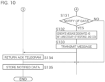
- Figs. 9 and 10 are flowcharts illustrating a communication protocol in the communication related to the centralized control.
- the centralized control device 10 performs communication for centralized monitoring and operation of each of the outdoor units 30 and each of the indoor units 50.
- the centralized control device 10 displays status of each of the outdoor units 30 and each of the indoor units 50 on the display unit 14 using icons, and performs air conditioning control and scheduled operation through an icon operation via the operation unit 15.
- a communication protocol between the centralized control device 10 and the indoor unit 50 will be described.
- the control unit 11 of the centralized control device 10 determines whether to acquire data of the indoor unit 50 (step S121).
- the control unit 11 may refer to the output of the built-in clock or the built-in timer to determine whether the current time point corresponds to a timing set as an acquisition timing, and determine whether to acquire the data of the indoor unit 50.
- a periodic timing is designated.
- the control unit 51 of the indoor unit 50 checks the CoAP header of the received message.
- the method is designated as "GET" in the CoAP header, the necessary or unnecessary of response is “necessary”, and thus the control unit 51 generates a message including the data requested by the centralized control device 10 and returns the message to the centralized control device 10 (step S124).
- the control unit 11 of the centralized control device 10 When receiving the reply message from the indoor unit 50, the control unit 11 of the centralized control device 10 causes the storage unit 12 to store the data included in the received message (step S125).
- the received message may be stored only in the volatile memory provided in the storage unit 12, or may be stored in the volatile memory and then copied and stored in the nonvolatile memory.
- the control unit 11 When determining to update the data of the indoor unit 50 (S126: YES), the control unit 11 generates a message including a CoAP header in which the method is designated as "SET”, the necessary or unnecessary of response is designated as “unnecessary”, and the necessary or unnecessary of retransmission is designated as "CON" (step S127). The control unit 11 transmits the generated message from the communication unit 13 to the indoor unit 50 as a destination (step S128).
- the indoor unit 50 basically only receives communication from the centralized control device 10, but may notify the centralized control device 10 of data when the internal state changes due to an operation of a remote controller, for example.
- the determinations are performed in the order of whether to acquire data, whether to update data of the partner, and whether to notify the partner of the data, but the order of these determinations is merely for convenience, and the determinations can be performed in any order.
- the present embodiment has a configuration in which, in a situation where a response is not necessary, the necessary or unnecessary of response is designated as "unnecessary", and no response is returned to a received request.
- the present embodiment has a configuration in which a telegram is retransmitted in the minimum necessary scene.
- a configuration will be described in which a message is transmitted from the outdoor unit 30 to the indoor unit 50 to designate a transmission timing of data when the indoor unit 50 detects a change in state.
- the change in state of the refrigeration and air conditioning-related unit represents, for example, changes in values of various sensors and actuators provided in the indoor unit 50.
- the outdoor unit 30 (first communication node) generates a message including information related to the transmission timing at which the indoor unit 50 should transmit data when the indoor unit 50 (second communication node) detects a change in state, and transmits the generated message to the indoor unit 50.
- the information related to the transmission timing is described in, for example, a payload of data following the CoAP header.
- the indoor unit 50 avoids load concentration on the outdoor unit 30 by transmitting the data according to the timing described in the message.
- Fig. 11 is an explanatory diagram illustrating a setting example of the transmission timing.
- the transmission timing is defined based on an elapsed time from a reference time synchronized in the plurality of indoor units 50, and is determined as a timing unique to each of the plurality of indoor units 50.
- transmission timings in three indoor units 50, 50, and 50 are shown.
- Time T0 indicates a reference time synchronized in the three indoor units 50, 50, and 50.
- Times T11, T12, T13, and so on indicate transmission timings determined for the first indoor unit 50
- times T21, T22, T23, and so on indicate transmission timings determined for the second indoor unit 50
- times T31, T32, T33, and so on indicate transmission timings determined for the third indoor unit 50.
- a time interval between the reference time and the first transmission timing is set to a value unique to each indoor unit 50. That is, T11 ⁇ T21 ⁇ T31. As described above, it is possible to shift the transmission timing of each of the indoor units 50 by the setting of the transmission timing of each indoor unit 50.
- Each of the indoor units 50 calculates a timing at which the information related to the change in state can be transmitted based on the transmission timing determined for the own device. For example, it is assumed that the change in state is detected in each of the indoor units 50 at a time TA shown in Fig. 11 as an operation command is transmitted from the centralized control device 10 to each of the indoor units 50 simultaneously. In this case, in the first indoor unit 50, since the earliest timing after the detection of the change in state is T14 of the plurality of transmission timings T11, T12, ..., the data transmission is delayed until that time. That is, the delay time of the first indoor unit 50 is T14-TA.
- the delay time of the second indoor unit 50 is T23-TA.
- the delay time of the third indoor unit 50 since the earliest timing after the detection of the change in state is T33 of the plurality of transmission timings T31, T32, ..., the data transmission is delayed until that time. That is, the delay time of the third indoor unit 50 is T33-TA.
- the cycle of the transmission timing set in each of the indoor units 50 is constant, but different cycles may be set between the indoor units 50 as long as the transmission timing does not overlap in two or more indoor units 50.
- the transmission timing of the indoor unit 50 can be appropriately set according to the number of indoor units 50 which should transmit data, the priority of the indoor units 50 which should transmit data, and the like.
- the transmission timing of the indoor unit 50 may be set based on the time that has elapsed since each of the indoor units 50 detects the change in state. For example, when each of the indoor units 50 detects the change in state at the time TA, the first indoor unit 50 may set the timing at which the time T1 has elapsed from the TA as a transmission timing, the second indoor unit 50 may set the timing at which T2 ( ⁇ T1) has elapsed from the time TA as a transmission timing, and the third indoor unit 50 may set the timing at which T3 ( ⁇ T1 ⁇ T2) has elapsed from the time TA as a transmission timing.
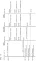
- Fig. 12 is a timing chart illustrating a communication protocol according to the second embodiment.
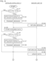
- the control unit 31 of the outdoor unit 30 generates a message including information related to the transmission timing at which each of the indoor units 50 should transmit data, and notifies each of the outdoor units 30 of the transmission timing by transmitting the generated message from the communication unit 33 to each of the indoor units 50 (step S201).
- step S201 since the notification is from the outdoor unit 30 to the indoor unit 50, the control unit 31 generates a message including a CoAP header in which the method is designated as "INF", the necessary or unnecessary of response is designated as “unnecessary”, and the necessary or unnecessary of retransmission is designated as "NON" and including a payload of data in which the transmission timing unique to each of the indoor units 50 is described, and transmits the message to each of the indoor units 50.
- the control unit 31 since the notification is from the outdoor unit 30 to the indoor unit 50, the control unit 31 generates a message including a CoAP header in which the method is designated as "INF”, the necessary or unnecessary of response is designated as “unnecessary”, and the necessary or unnecessary of retransmission is designated as "NON" and including a payload of data in which the transmission timing unique to each of the indoor units 50 is described, and transmits the message to each of the indoor units 50.
- the control unit 51 of each of the indoor units 50 checks the CoAP header of the received message.
- the control unit 51 does not reply to the received message and causes the storage unit 52 to store data including the transmission timing (steps S202 to S204).
- the received message may be stored only in the volatile memory provided in the storage unit 52, or may be stored in the volatile memory and then copied and stored in the nonvolatile memory.
- the control unit 51 of each of the indoor units 50 monitors states of the sensors and actuators provided therein.
- the control unit 51 calculates a timing at which the own device can transmit data, based on the transmission timing stored in the storage unit 52 (steps S208 to S210).
- the transmission timing of the own device may be stored in the volatile memory provided in the storage unit 52, or may be stored in the nonvolatile memory.
- Each of the indoor units 50 determines whether the current time point is a transmittable timing, generates a message including information related to the change in state when determining to be at the transmittable timing, and transmits the generated message from the communication unit 53 to the outdoor unit 30, thereby notifying the outdoor unit 30 of the change in state (steps S211 to S213).
- control unit 31 since the notification is in association with the change in state from the indoor unit 50 to the outdoor unit 30, the control unit 31 generates a message including a CoAP header in which the method is designated as "INF”, the necessary or unnecessary of response is designated as “unnecessary”, and the necessary or unnecessary of retransmission is designated as "CON”, and including the information related to the change in state in the data, and transmits the message to the outdoor unit 30.
- the outdoor unit 30 Every time receiving the message transmitted from each of the indoor units 50, the outdoor unit 30 returns an ACK telegram and causes the storage unit 32 to store the information related to the change in state of each of the indoor units 50 (steps S214 to S216).
- the received message may be stored only in the volatile memory provided in the storage unit 32, or may be stored in the volatile memory and then copied and stored in the nonvolatile memory.
Landscapes
- Engineering & Computer Science (AREA)
- Chemical & Material Sciences (AREA)
- Combustion & Propulsion (AREA)
- Mechanical Engineering (AREA)
- General Engineering & Computer Science (AREA)
- Human Computer Interaction (AREA)
- Signal Processing (AREA)
- Computer Networks & Wireless Communication (AREA)
- Physics & Mathematics (AREA)
- Fuzzy Systems (AREA)
- Mathematical Physics (AREA)
- Air Conditioning Control Device (AREA)
- Small-Scale Networks (AREA)
Abstract
Description
- The present invention relates to a communication method, a refrigeration and air conditioning-related system, and a communication node.
- In a large-scale refrigeration and air conditioning-related system, for example, a network for communication is constructed in which a plurality of outdoor units are connected to one centralized control device and a plurality of indoor units are connected to each of the outdoor units (see, for example, PTL 1). Various types of data are transmitted and received between a plurality of devices including the centralized control device, the outdoor units, and the indoor units, and centralized control, cooperative operation, and the like of the devices are achieved.
- PTL 1:
Japanese Unexamined Patent Application Publication No. 2008-20092 - An object of the present disclosure is to provide a communication method, a refrigeration and air conditioning-related system, and a communication node that can prevent an increase in a processing load on a specific device. Solution to Problem
- An aspect of the present disclosure provides a communication method for communicating data regarding a change in state of a refrigeration and air conditioning-related unit between a plurality of communication nodes, in which a first communication node generates a message including information regarding a timing at which, when a second communication node detects a change in state, the second communication node transmits data to a communication node to which the data is to be transmitted, and transmits the message generated to the second communication node.
- In the communication method according to the aspect of the present disclosure, desirably, the second communication node delays, when detecting the change in state, transmission of the data based on the information regarding the timing included in the message received.
- In the communication method according to the aspect of the present disclosure, desirably, the timing is determined as an earliest timing after the change in state is detected among a plurality of timings uniquely determined for the second communication node.
- In the communication method according to the aspect of the present disclosure, desirably, the timing is defined based on an elapsed time from when the change in state is detected.
- In the communication method according to the aspect of the present disclosure, desirably, the timing is defined based on an elapsed time from a reference time synchronized between second communication nodes.
- In the communication method according to the aspect of the present disclosure, desirably, the timing is defined based on the number and order of communication nodes which are to transmit data.
- In the communication method according to the aspect of the present disclosure, desirably, the first communication node is an outdoor unit and the second communication node is an indoor unit.
- In the communication method according to the aspect of the present disclosure, desirably, the first communication node further includes a centralized control device.
- In the communication method according to the aspect of the present disclosure, desirably, the first communication node further includes a service checker.
- In the communication method according to the aspect of the present disclosure, desirably, the message has a format defined by Constrained Application Protocol (CoAP), and the information regarding the timing is described in a payload in the message.
- An aspect of the present disclosure provides a refrigeration and air conditioning-related system for communicating data regarding a change in state of a refrigeration and air conditioning-related unit between a plurality of communication nodes, in which a first communication node includes a control unit, and a communication unit, the control unit generates a message including information regarding a timing at which, when a second communication node detects a change in state, the second communication node transmits data to a communication node to which the data is to be transmitted, and the communication unit transmits the message generated by the control unit to the second communication node.
- An aspect of the present disclosure provides a communication node in a refrigeration and air conditioning-related system, including a control unit, and a communication unit, in which the control unit generates a message including information regarding a timing at which, when an other communication node detects a change in state of a refrigeration and air conditioning-related unit, the other communication node transmits data to a communication node to which the data is to be transmitted, and the communication unit transmits the message generated by the control unit to the other communication node.
- According to the present disclosure, it is possible to prevent an increase in a processing load on a specific device.
-
- [
Fig. 1] Fig. 1 is a schematic diagram showing a configuration example of a refrigeration and air conditioning-related system according to an embodiment. - [
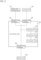
Fig. 2] Fig. 2 is a block diagram illustrating a configuration example of an outdoor unit. - [
Fig. 3] Fig. 3 is a block diagram illustrating a configuration example of an indoor unit. - [
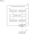
Fig. 4] Fig. 4 is a block diagram illustrating a configuration example of a centralized control device. - [
Fig. 5] Fig. 5 is a block diagram showing a configuration example of a relay device. - [
Fig. 6] Fig. 6 is a conceptual diagram showing a format of a message (telegram) transmitted and received between devices. - [
Fig. 7] Fig. 7 is a flowchart illustrating a communication protocol in communication related to refrigerant control. - [
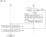
Fig. 8] Fig. 8 is a flowchart illustrating the communication protocol in communication related to refrigerant control. - [
Fig. 9] Fig. 9 is a flowchart illustrating a communication protocol in communication related to centralized control. - [
Fig. 10] Fig. 10 is a flowchart illustrating the communication protocol in communication related to centralized control. - [
Fig. 11] Fig. 11 is an explanatory diagram illustrating a setting example of a transmission timing. - [
Fig. 12] Fig. 12 is a timing chart illustrating a communication protocol in a second embodiment. - Hereinafter, a refrigeration and air conditioning-related system according to embodiments will be specifically described with reference to the drawings. It should be noted that the present technology is not limited to these examples, but is indicated by the scope of claims, and is intended to include all modifications within the meaning and scope equivalent to the scope of the claims.
-
Fig. 1 is a schematic diagram showing a configuration example of a refrigeration and air conditioning-related system according to an embodiment. A refrigeration and air conditioning-related system 1 according to the embodiment is a system for communicating information related to a refrigeration and air conditioning-related unit between a plurality of communication nodes. The communication nodes constituting the refrigeration and air conditioning-related system 1 include refrigeration and air conditioning-related devices, for example, acentralized control device 10, anoutdoor unit 30, anindoor unit 50, and arelay device 70. The information transmitted and received between the communication nodes is information related to the refrigeration and air conditioning-related unit, and includes information related to refrigerant control, information related to a centralized monitoring operation, and the like. Here, the information related to the refrigeration and air conditioning-related unit may be information of the device itself, or may be information related to some of elements constituting the refrigeration and air conditioning-related device. - The communication nodes are not limited to those described above, and may include various refrigeration and air conditioning-related devices such as a service checker, a remote controller, a ventilator, a communication device, and a control device. In the following description, the refrigeration and air conditioning-related devices connected to the refrigeration and air conditioning-
related system 1 as the communication nodes will also be simply referred to as devices. - In the refrigeration and air conditioning-
related system 1 shown inFig. 1 , onecentralized control device 10 and a plurality ofoutdoor units 30 are connected via a transmission line. In the present embodiment, a plurality of devices are connected in a daisy chain manner. That is, a firstoutdoor unit 30 is connected to thecentralized control device 10 via a first transmission line, a secondoutdoor unit 30 is connected to the firstoutdoor unit 30 via a second transmission line, and a thirdoutdoor unit 30 is connected to the secondoutdoor unit 30 via a third transmission line. Here, the plurality of transmission lines connecting thecentralized control device 10 and the plurality ofoutdoor units 30 are electrically conducted. Therefore, for example, a signal transmitted by thecentralized control device 10 can be received by all theoutdoor units 30 connected in a daisy chain manner, and a signal transmitted by any one of theoutdoor units 30 can be received by thecentralized control device 10 and all the otheroutdoor units 30. - In the refrigeration and air conditioning-
related system 1, a plurality ofindoor units 50 are connected to eachoutdoor unit 30 via a transmission line in a daisy chain manner. That is, a firstindoor unit 50 is connected to oneoutdoor unit 30 via a first transmission line, and a secondindoor unit 50 is connected to the firstindoor unit 50 via a second transmission line. The plurality of transmission lines connecting theoutdoor unit 30 and the plurality ofindoor units 50 are electrically conducted, and a signal transmitted by any of the devices can be received by all the devices connected in a daisy chain manner. - Each of the
outdoor units 30 is connected to a transmission line for communicating with thecentralized control device 10 and the otheroutdoor units 30, and a transmission line for communicating with theindoor unit 50. In the present embodiment, the two transmission lines are electrically conducted inside theoutdoor unit 30. Therefore, for example, thecentralized control device 10 can communicate with theindoor unit 50 via theoutdoor unit 30. In addition, theindoor unit 50 connected to a firstoutdoor unit 30 can communicate with anotherindoor unit 50 connected to a secondoutdoor unit 30 via the firstoutdoor unit 30 and the secondoutdoor unit 30. The transmission line for communicating with thecentralized control device 10 and the otheroutdoor units 30 may be electrically isolated from the transmission line for communicating with theindoor unit 50 within theoutdoor unit 30. - The refrigeration and air conditioning-
related system 1 may also include therelay device 70. For example, when a distance between two devices to be directly connected via a transmission line is long and a length of the transmission line exceeds a predetermined length, therelay device 70 is provided between these devices. The refrigeration and air conditioning-related system 1 illustrated inFig. 1 is provided with tworelay devices 70 connected between twoindoor units relay device 70 is connected to a firstindoor unit 50 via a first transmission line, and a secondindoor unit 50 is connected to therelay device 70 via a second transmission line. - The
relay device 70 may be provided at any position in the refrigeration and air conditioning-relatedsystem 1. For example, therelay device 70 may be provided between thecentralized control device 10 and theoutdoor unit 30, between the twooutdoor units outdoor unit 30 and theindoor unit 50. In addition, therelay device 70 may be provided between various devices other than thecentralized control device 10, theoutdoor unit 30, and theindoor unit 50. Therelay device 70 is not essential, and the refrigeration and air conditioning-relatedsystem 1 may be constructed without including therelay device 70. -
Fig. 2 is a block diagram illustrating a configuration example of theoutdoor unit 30. Theoutdoor unit 30 includes, for example, acontrol unit 31, astorage unit 32, acommunication unit 33, andconnection terminals 34 to 36. Thecontrol unit 31 is configured with, for example, an arithmetic processing device such as a microcomputer or a central processing unit (CPU). Thecontrol unit 31 performs various types of processing by reading and executing programs stored in thestorage unit 32. Thecontrol unit 31 performs various types of control processing, for example, control of the operation of each unit of theoutdoor unit 30 and control of communication with thecentralized control device 10, anotheroutdoor unit 30, theindoor unit 50, and the like. Thecontrol unit 31 includes a built-in clock for outputting time information, a built-in timer for measuring elapsed time, and the like. - The
storage unit 32 includes, for example, a nonvolatile memory such as a flash memory or an electrically erasable programmable read only memory (EEPROM), and a volatile memory such as a dynamic random access memory (DRAM) or a static random access memory (SRAM). Thestorage unit 32 stores various programs to be executed by thecontrol unit 31 and various kinds of data necessary for control processing of thecontrol unit 31. Various programs are stored in the nonvolatile memory. On the other hand, various kinds of data may be stored only in the volatile memory, or may be stored in the volatile memory and then copied and stored in the nonvolatile memory. - The
communication unit 33 is configured with, for example, a transceiver integrated circuit (IC). Thecommunication unit 33 communicates with thecentralized control device 10, the otheroutdoor unit 30, and theindoor unit 50 via transmission lines connected to a plurality ofconnection terminals 34 to 36 provided in theoutdoor unit 30. Thecommunication unit 33 modulates data to be transmitted and received by, for example, orthogonal frequency division multiplexing (OFDM) scheme. Specifically, thecommunication unit 33 performs multi-carrier transmission using a frequency band of 2 to 28 MHz. Thecommunication unit 33 transmits data by outputting a signal obtained by modulating transmission data supplied from thecontrol unit 31 to the transmission line, and supplies data obtained by acquiring and demodulating a signal on the transmission line to thecontrol unit 31 as reception data. - The
communication unit 33 may have a multi-hop function. The multi-hop function is a function in which, when a second device receives a signal transmitted from a first device, the second device outputs the same signal as the received signal to a transmission line. Since each device outputs the same signal as the received signal, attenuation of the signal can be reduced, and the transmission distance of the signal can be extended. - Three
connection terminals 34 to 36 are configured by using an electronic component such as a connector or a socket, and the transmission line for communication is detachably connected thereto. In theoutdoor unit 30 according to the present embodiment, the threeconnection terminals 34 to 36 are electrically conducted via, for example, a wiring pattern on a circuit board, and are electrically connected to thecommunication unit 33. Therefore, a signal input from any one of theconnection terminals 34 to 36 is output from theother connection terminals 34 to 36 and is input to thecommunication unit 33. The signal output by thecommunication unit 33 is output from theconnection terminals 34 to 36. In the present embodiment, the threeconnection terminals 34 to 36 are directly conducted via the wiring pattern or the like, but, for example, a filter circuit or the like may be provided between theconnection terminals 34 to 36. The number of connection terminals provided in theoutdoor unit 30 may be two or less, or four or more. -
Fig. 3 is a block diagram illustrating a configuration example of theindoor unit 50. Theindoor unit 50 includes acontrol unit 51, astorage unit 52, acommunication unit 53, and twoconnection terminals control unit 51 is configured with an arithmetic processing device such as a microcomputer or a CPU. Thecontrol unit 51 performs various types of control processing, for example, control of the operation of each unit of theindoor unit 50 and control of communication with thecentralized control device 10, theoutdoor unit 30, anotherindoor unit 50, and the like. Thecontrol unit 51 includes a built-in clock for outputting time information, a built-in timer for measuring elapsed time, and the like. - The
storage unit 52 includes, for example, a nonvolatile memory such as a flash memory or an EEPROM, and a volatile memory such as a DRAM or an SRAM. Thestorage unit 52 stores various programs to be executed by thecontrol unit 51 and various kinds of data necessary for control processing of thecontrol unit 51. Various programs are stored in the nonvolatile memory. On the other hand, various kinds of data may be stored only in the volatile memory, or may be stored in the volatile memory and then copied and stored in the nonvolatile memory. - The
communication unit 53 is configured with, for example, a transceiver IC. Thecommunication unit 53 has the function similar to that of thecommunication unit 33 of theoutdoor unit 30, and an IC can be used that is the same as or similar to the IC used in thecommunication unit 33 of theoutdoor unit 30. Thecommunication unit 53 has a modulation function using an OFDM scheme and a multi-hop function, and communicates with thecentralized control device 10, theoutdoor unit 30, the otherindoor unit 50, and the like via the transmission lines connected to theconnection terminals indoor unit 50. Thecommunication unit 53 transmits data by outputting a signal obtained by modulating transmission data supplied from thecontrol unit 51 to the transmission line, and supplies data obtained by acquiring and demodulating a signal on the transmission line to thecontrol unit 51 as reception data. - Two
connection terminals connection terminals communication unit 53. The number of connection terminals provided in theindoor unit 50 may be one, or three or more. -
Fig. 4 is a block diagram illustrating a configuration example of thecentralized control device 10. Thecentralized control device 10 includes, for example, acontrol unit 11, astorage unit 12, acommunication unit 13, adisplay unit 14, anoperation unit 15, and aconnection terminal 16. Thecontrol unit 11 is configured with an arithmetic processing device such as a CPU. Thecontrol unit 11 performs various types of control processing, for example, control of the operation of each unit of thecentralized control device 10 and control of communication with theoutdoor unit 30, theindoor unit 50, and the like. Thecontrol unit 11 includes a built-in clock for outputting time information, a built-in timer for measuring elapsed time, and the like. - The
storage unit 12 includes a nonvolatile memory such as a flash memory or an EEPROM (or a magnetic storage device such as a hard disk) and a volatile memory such as a DRAM or an SRAM. Thestorage unit 12 stores various programs to be executed by thecontrol unit 11 and various kinds of data necessary for control processing of thecontrol unit 11. Various programs are stored in the nonvolatile memory. On the other hand, various kinds of data may be stored only in the volatile memory, or may be stored in the volatile memory and then copied and stored in the nonvolatile memory. - The
communication unit 13 is configured with, for example, a transceiver IC. Thecommunication unit 13 has the function similar to that of thecommunication unit 33 of theoutdoor unit 30 and thecommunication unit 53 of theindoor unit 50, and an IC can be used that is the same as or similar to the IC used in thecommunication unit 33 of theoutdoor unit 30 and thecommunication unit 53 of theindoor unit 50. Thecommunication unit 13 has a modulation function using an OFDM scheme and a multi-hop function, and communicates with theoutdoor unit 30, theindoor unit 50, and the like via a transmission line connected to theconnection terminal 16 provided in thecentralized control device 10. Thecommunication unit 13 transmits data by outputting a signal obtained by modulating transmission data supplied from thecontrol unit 11 to the transmission line, and supplies data obtained by acquiring and demodulating a signal on the transmission line to thecontrol unit 11 as reception data. - The
display unit 14 is configured with a liquid crystal display or the like, and displays various images, characters, and the like under the control of thecontrol unit 11. Theoperation unit 15 accepts a user's operation and notifies thecontrol unit 11 of the accepted operation. For example, theoperation unit 15 accepts the user's operation through an input device such as a mechanical button or a touch panel provided on the surface of thedisplay unit 14. Furthermore, for example, theoperation unit 15 may be input devices such as a mouse and a keyboard, and these input devices may be configured to be detachable from thecentralized control device 10. Theconnection terminal 16 is configured using, for example, an electronic component such as a connector or a socket, and a transmission line for communication is detachably connected thereto. Theconnection terminal 16 is electrically connected to thecommunication unit 13 via, for example, a wiring pattern on a circuit board. The number of connection terminals provided in thecentralized control device 10 may be two or more. -
Fig. 5 is a block diagram showing a configuration example of therelay device 70. Therelay device 70 according to the present embodiment is configured to include, for example, acommunication unit 71 and twoconnection terminals communication unit 71 is configured using, for example, a transceiver IC. Thecommunication unit 71 has the function similar to that of thecommunication unit 33 of theoutdoor unit 30, thecommunication unit 53 of theindoor unit 50, and thecommunication unit 13 of thecentralized control device 10, and an IC can be used that is the same as or similar to the IC used in these units. Thecommunication unit 71 has a modulation function using an OFDM scheme and a multi-hop function, and communicates with thecentralized control device 10, theoutdoor unit 30, theindoor unit 50, and the like via the transmission lines connected to theconnection terminals relay device 70. Thecommunication unit 71 of therelay device 70 may have at least the multi-hop function, and does not necessarily have the modulation function using the OFDM scheme. - Two
connection terminals connection terminals communication unit 71. The number of connection terminals provided in therelay device 70 may be one or three or more. - In the refrigeration and air conditioning-related
system 1, the plurality of devices such as thecentralized control device 10, theoutdoor unit 30, theindoor unit 50, and therelay device 70 are connected in a daisy chain manner via the transmission lines, and perform multi-carrier communication by the OFDM modulation scheme. The plurality of transmission lines connecting the plurality of devices are electrically conducted, and a signal transmitted by one device can be received by all the other devices. When each of the devices has a multi-hop function of outputting the same signal as the received signal to the transmission line, it is possible to extend the transmission distance of the signal by increasing the intensity of the signal that attenuates according to the transmission distance from the transmission source. - An example of a communication scheme capable of using the OFDM modulation and the multi-hop function includes a communication scheme of high definition power line communication (HD-PLC). The communication unit of each of the devices may be configured with, for example, a transceiver IC that employs the communication scheme of HD-PLC. The communication scheme of HD-PLC performs communication via a power line, but each of the devices in the refrigeration and air conditioning-related
system 1 according to the embodiment does not perform communication via a power line, but performs communication via a transmission line provided separately from the power line. -
Fig. 6 is a conceptual diagram showing a format of a message (telegram) transmitted and received between the devices. A communication protocol used in the refrigeration and air conditioning-relatedsystem 1 according to the embodiment is as follows. HD-PLC and Ethernet (registered trademark) are used for a physical/data link layer. IPv6 is used for a network layer. User datagram protocol (UDP) is used for a transport layer. Constrained Application Protocol (CoAP) is used for an application layer. - A message transmitted and received between the devices includes headers (that is, an HD-PLC header, an IPv6 header, a UDP header, and a CoAP header) corresponding to the respective layers and data in which transmitting contents are described.
- The IPv6 is suitable for the refrigeration and air conditioning-related
system 1. Various devices connected so as to be mutually accessible are identified by IP addresses with a common specification, and can perform communication. - The UDP is suitable for the refrigeration and air conditioning-related
system 1. Even when a large number ofindoor units 50 are connected to theoutdoor unit 30, since no connection is established as in TPC, the memory of theoutdoor unit 30 is not used up. - The CoAP is suitable for the refrigeration and air conditioning-related
system 1. Since a binary format message is used, communication lighter than HTTP is possible. A request and a response can correspond to each other, and data can be retransmitted when the request fails. In addition, when a method to be described below is designated, it is possible to acquire and update data related to control, operating status, and the like between the devices. - In the embodiment, when one device (first communication node) transmits information to another device (second communication node), the first communication node as a transmission source generates a message including a code indicating an attribute of the information and a type indicating a necessary or unnecessary of response to be designated according to the attribute, and transmits the generated message to the second node as a destination.
- The code indicating the attribute of the information represents an operation on data and is also called a method. In the embodiment, "GET" representing an operation of acquiring data of a partner, "SET" representing an operation of updating data of the partner, "INF" representing an operation of notifying its own data, and the like can be used as methods. Since a response is necessary to acquire data, a necessary of response is designated as a type for the method "GET". On the other hand, since a response is unnecessary for an operation of updating a value or an operation of notifying information, an unnecessary of response is designated as a type for the methods "SET" and "INF". The method is not limited to the above, and may include "DELETE" or the like representing an operation of deleting data of the partner.
- Further, a necessary or unnecessary of retransmission may be defined in a message transmitted and received in the refrigeration and air conditioning-related
system 1. For example, even when a message to be periodically transmitted does not reach the destination for some reason, the message may be transmitted at the next transmission timing, and thus retransmission is not necessary. On the other hand, when a user operation is performed using theoperation unit 15 of thecentralized control device 10 or a remote controller, an operation result needs to be reflected in a relatively short time (several seconds), high reliability is required, and thus retransmission is necessary. - The above-described methods, the necessary or unnecessary of response, and the necessary or unnecessary of retransmission can be described in a CoAP header. As the methods "GET", "SET", and "INF", for example, "GET", "POST", and "PUT" defined in CoAP may be used, respectively, and can be designated in the CoAP header.
- Further, a "No Server Response" option of the CoAP can be used for whether a response is necessary. That is, "0" may be designated in the CoAP header when a response is necessary, and "0x32" may be designated in the CoAP header when a response is unnecessary.
- Further, the necessary or unnecessary of retransmission is described in a type field of the CoAP header. That is, "CON (= Confirmable-message)" may be designated when retransmission is necessary, and "NON (= Non-Confirmable message)" may be designated when retransmission is unnecessary. The device, which has received a telegram, checks the type field of the CoAP header, and returns an ACK telegram in the case of CON. When not receiving the ACK telegram for a certain period of time, a transmitting side retransmits the telegram.
- Hereinafter, an application example in the refrigeration and air conditioning-related
system 1 will be described. - The communication in the refrigeration and air conditioning-related
system 1 broadly includes communication related to refrigerant control and communication related to centralized control. The communication related to the refrigerant control is mainly communication between theoutdoor unit 30 and theindoor unit 50 connected by a refrigerant pipe, and is communication for performing air conditioning by appropriately controlling the devices. On the other hand, the communication related to the centralized control is communication for centrally monitoring and operating theoutdoor unit 30 and theindoor unit 50 from thecentralized control device 10. -
Figs. 7 and8 are flowcharts illustrating a communication protocol in the communication related to the refrigerant control. In the communication related to the refrigerant control, oneoutdoor unit 30 serves as a parent in a refrigerant system, and communicates with a plurality of indoor units 50 (children) and other outdoor units 30 (parents). In the flowchart ofFig. 7 , for simplification, a communication protocol between oneoutdoor unit 30 serving as a parent and oneindoor unit 50 serving as a child will be described. Each of theoutdoor unit 30 and theindoor unit 50 internally stores data of a communication partner and updates the data by communication. Theoutdoor unit 30 and theindoor unit 50 determine their own operations with reference to the data stored therein. - The
control unit 31 of theoutdoor unit 30 determines whether to acquire data of the indoor unit 50 (step S101). Thecontrol unit 31 may refer to the output of the built-in clock or the built-in timer to determine whether the current time point corresponds to a timing set as an acquisition timing, and determine whether to acquire the data of theindoor unit 50. As the acquisition timing for data, for example, a periodic timing is designated. - When determining to acquire the data of the indoor unit 50 (S101: YES), the
control unit 31 generates a message including a CoAP header in which the method is designated as "GET", the necessary or unnecessary of response is designated as "necessary", and the necessary or unnecessary of retransmission is designated as "NON" (step S102). Thecontrol unit 31 transmits the generated message from thecommunication unit 33 to theindoor unit 50 as a destination (step S103). - When receiving the message transmitted from the
outdoor unit 30, thecontrol unit 51 of theindoor unit 50 checks the CoAP header of the received message. When the method is designated as "GET" in the CoAP header, the necessary or unnecessary of response is "necessary", and thus thecontrol unit 51 generates a message including the data requested by theoutdoor unit 30 and returns the message to the outdoor unit 30 (step S104). - When receiving the reply message from the
indoor unit 50, thecontrol unit 31 of theoutdoor unit 30 causes thestorage unit 32 to store the data included in the received message (step S105). Here, the received message may be stored only in the volatile memory provided in thestorage unit 32, or may be stored in the volatile memory and then copied and stored in the nonvolatile memory. - Next, the
control unit 31 of theoutdoor unit 30 determines whether to update the data of the indoor unit 50 (step S106). Thecontrol unit 31 may refer to the output of the built-in clock or the built-in timer to determine whether the current time point corresponds to a timing set as an update timing, and determine whether to update the data of theindoor unit 50. For example, a periodic timing is designated as the data update timing. - When determining to update the data of the indoor unit 50 (S106: YES), the
control unit 31 generates a message including a CoAP header in which the method is designated as "SET", the necessary or unnecessary of response is designated as "unnecessary", and the necessary or unnecessary of retransmission is designated as "NON" (step S107). Thecontrol unit 31 transmits the generated message from thecommunication unit 33 to theindoor unit 50 as a destination (step S108). - When receiving the message transmitted from the
outdoor unit 30, thecontrol unit 51 of theindoor unit 50 checks the CoAP header of the received message. When the method is designated as "SET" in the CoAP header, the necessary or unnecessary of response is "unnecessary", and thus thecontrol unit 51 does not reply to the received message and updates the data stored in the storage unit 52 (step S109). The data to be updated may be stored in the volatile memory provided in thestorage unit 52 or the nonvolatile memory. - Next, the
control unit 31 of theoutdoor unit 30 determines whether to notify theindoor unit 50 of its own data (step S110). Thecontrol unit 31 may refer to the output of the built-in clock or the built-in timer to determine whether the current time point corresponds to a timing set as a notification timing, and determine whether to notify theindoor unit 50. As the timing of notification to theindoor unit 50, for example, a periodic timing is designated. Further, as the timing of notification to theindoor unit 50, a timing may be designated at which an internal state has changed. Here, the change in the internal state represents a change in the values of various sensors or actuators provided in the device or a change in the control state. - When determining to notify the
indoor unit 50 of the data (S110: YES), thecontrol unit 31 generates a message including a CoAP header in which the method is designated as "INF", the necessary or unnecessary of response is designated as "unnecessary", and the necessary or unnecessary of retransmission is designated as "NON" (step S111). Thecontrol unit 31 transmits the generated message from thecommunication unit 33 to theindoor unit 50 as a destination (step S112). - When receiving the message transmitted from the
outdoor unit 30, thecontrol unit 51 of theindoor unit 50 checks the CoAP header of the received message. When the method is designated as "INF" in the CoAP header, the necessary or unnecessary of response is "unnecessary", and thus thecontrol unit 51 does not reply to the received message and causes thestorage unit 52 to store the notified data (step S113). Here, the received message may be stored only in the volatile memory provided in thestorage unit 52, or may be stored in the volatile memory and then copied and stored in the nonvolatile memory. - The
indoor unit 50 basically only receives communication from theoutdoor unit 30, but may notify theoutdoor unit 30 of data when the internal state changes due to an operation of a remote controller, for example. - The
control unit 51 of theindoor unit 50 determines whether to notify theindoor unit 50 of its own data (step S114). When there is a change in the internal state of the own device and it is determined to notify the data (S114: YES), thecontrol unit 51 generates a message including a CoAP header in which the method is designated as "INF", the necessary or unnecessary of response is designated as "unnecessary", and the necessary or unnecessary of retransmission is designated as "CON" (step S115). Thecontrol unit 51 transmits the generated message from thecommunication unit 53 to theoutdoor unit 30 as a destination (step S116). - When receiving the message transmitted from the
indoor unit 50, thecontrol unit 31 of theoutdoor unit 30 checks the CoAP header of the received message. When the method is designated as "INF" in the CoAP header, the necessary or unnecessary of response is "unnecessary", but the necessary or unnecessary of retransmission is "CON", so that thecontrol unit 31 returns an ACK telegram from the communication unit 33 (step S117). Further, thecontrol unit 31 causes thestorage unit 32 to store the data included in the message received from the indoor unit 50 (step S118). Here, the received message may be stored only in the volatile memory provided in thestorage unit 32, or may be stored in the volatile memory and then copied and stored in the nonvolatile memory. - When not receiving the ACK telegram for a certain period of time after transmitting the message in step S115, the
control unit 51 of theindoor unit 50 retransmits the message. When retransmitting the message, thecontrol unit 51 may update the content of the data to be transmitted to the latest content and retransmit the message. - In the flowcharts shown in
Figs. 7 and8 , the determinations are performed in the order of whether to acquire data, whether to update data of the partner, and whether to notify the partner of the data, but the order of these determinations is merely for convenience, and the determinations can be performed in any order. -
Figs. 9 and10 are flowcharts illustrating a communication protocol in the communication related to the centralized control. In communication related to centralized control, thecentralized control device 10 performs communication for centralized monitoring and operation of each of theoutdoor units 30 and each of theindoor units 50. Thecentralized control device 10 displays status of each of theoutdoor units 30 and each of theindoor units 50 on thedisplay unit 14 using icons, and performs air conditioning control and scheduled operation through an icon operation via theoperation unit 15. In the flowcharts shown inFigs. 9 and10 , for simplification, a communication protocol between thecentralized control device 10 and theindoor unit 50 will be described. - The
control unit 11 of thecentralized control device 10 determines whether to acquire data of the indoor unit 50 (step S121). Thecontrol unit 11 may refer to the output of the built-in clock or the built-in timer to determine whether the current time point corresponds to a timing set as an acquisition timing, and determine whether to acquire the data of theindoor unit 50. As the acquisition timing for data, for example, a periodic timing is designated. - When determining to acquire the data of the indoor unit 50 (S121: YES), the
control unit 11 generates a message including a CoAP header in which the method is designated as "GET", the necessary or unnecessary of response is designated as "necessary", and the necessary or unnecessary of retransmission is designated as "NON" (step S122). Thecontrol unit 11 transmits the generated message from thecommunication unit 13 to theindoor unit 50 as a destination (step S123). - When receiving the message transmitted from the
centralized control device 10, thecontrol unit 51 of theindoor unit 50 checks the CoAP header of the received message. When the method is designated as "GET" in the CoAP header, the necessary or unnecessary of response is "necessary", and thus thecontrol unit 51 generates a message including the data requested by thecentralized control device 10 and returns the message to the centralized control device 10 (step S124). - When receiving the reply message from the
indoor unit 50, thecontrol unit 11 of thecentralized control device 10 causes thestorage unit 12 to store the data included in the received message (step S125). Here, the received message may be stored only in the volatile memory provided in thestorage unit 12, or may be stored in the volatile memory and then copied and stored in the nonvolatile memory. - Next, the
control unit 11 of thecentralized control device 10 determines whether to update the data of the indoor unit 50 (step S126). For example, when a change in state occurs due to an icon operation via theoperation unit 15 or a schedule, thecontrol unit 11 determines to update the data of theindoor unit 50. - When determining to update the data of the indoor unit 50 (S126: YES), the
control unit 11 generates a message including a CoAP header in which the method is designated as "SET", the necessary or unnecessary of response is designated as "unnecessary", and the necessary or unnecessary of retransmission is designated as "CON" (step S127). Thecontrol unit 11 transmits the generated message from thecommunication unit 13 to theindoor unit 50 as a destination (step S128). - When receiving the message transmitted from the
centralized control device 10, thecontrol unit 51 of theindoor unit 50 checks the CoAP header of the received message. When the method is designated as "SET" in the CoAP header, the necessary or unnecessary of response is "unnecessary", but the necessary or unnecessary of retransmission is "CON", so that thecontrol unit 51 returns an ACK telegram from the communication unit 53 (step S129). In addition, thecontrol unit 51 updates the data stored in thestorage unit 52 in response to the "SET" request (step S130). The data to be updated may be stored in the volatile memory provided in thestorage unit 52 or the nonvolatile memory. - When not receiving the ACK telegram for a certain period of time after transmitting the message in step S128, the
control unit 11 of thecentralized control device 10 retransmits the message. When retransmitting the message, thecontrol unit 11 may update the content of the data to be transmitted to the latest content and retransmit the message. - The
indoor unit 50 basically only receives communication from thecentralized control device 10, but may notify thecentralized control device 10 of data when the internal state changes due to an operation of a remote controller, for example. - The
control unit 51 of theindoor unit 50 determines whether to notify thecentralized control device 10 of its own data (step S131). When there is a change in the internal state of the own device and it is determined to notify the data (S131: YES), thecontrol unit 51 generates a message including a CoAP header in which the method is designated as "INF", the necessary or unnecessary of response is designated as "unnecessary", and the necessary or unnecessary of retransmission is designated as "CON" (step S132). Thecontrol unit 51 transmits the generated message from thecommunication unit 53 to the centralized control device 10 (step S133). - When receiving the message transmitted from the
indoor unit 50, thecontrol unit 11 of thecentralized control device 10 checks the CoAP header of the received message. When the method is designated as "INF" in the CoAP header, the necessary or unnecessary of response is "unnecessary", but the necessary or unnecessary of retransmission is "CON", so that thecontrol unit 11 returns an ACK telegram from the communication unit 13 (step S134). Further, thecontrol unit 11 causes thestorage unit 32 to store the data included in the message received from the indoor unit 50 (step S135). Here, the received message may be stored only in the volatile memory provided in thestorage unit 32, or may be stored in the volatile memory and then copied and stored in the nonvolatile memory. - When not receiving the ACK telegram for a certain period of time after transmitting the message in step S133, the
control unit 51 of theindoor unit 50 retransmits the message. When retransmitting the message, thecontrol unit 51 may update the content of the data to be transmitted to the latest content and retransmit the message. - In the flowcharts shown in
Figs. 9 and10 , the determinations are performed in the order of whether to acquire data, whether to update data of the partner, and whether to notify the partner of the data, but the order of these determinations is merely for convenience, and the determinations can be performed in any order. - Generally, a relationship between a request and a response is defined in communication, but the present embodiment has a configuration in which, in a situation where a response is not necessary, the necessary or unnecessary of response is designated as "unnecessary", and no response is returned to a received request. In addition, although there is a case where a telegram is retransmitted in order to secure reliability, the present embodiment has a configuration in which a telegram is retransmitted in the minimum necessary scene. With the above-described configuration, according to the present embodiment, it is possible to secure a communication band and to reduce a load on each of the devices.
- In a second embodiment, a configuration will be described in which a message is transmitted from the
outdoor unit 30 to theindoor unit 50 to designate a transmission timing of data when theindoor unit 50 detects a change in state. - In the second embodiment, when data relating to the change in state of the refrigeration and air conditioning-related unit is transmitted from the
indoor unit 50 to theoutdoor unit 30, time slicing is performed so that the load is not concentrated on theoutdoor unit 30. Here, the change in state of the refrigeration and air conditioning-related unit represents, for example, changes in values of various sensors and actuators provided in theindoor unit 50. - Specifically, the outdoor unit 30 (first communication node) generates a message including information related to the transmission timing at which the
indoor unit 50 should transmit data when the indoor unit 50 (second communication node) detects a change in state, and transmits the generated message to theindoor unit 50. The information related to the transmission timing is described in, for example, a payload of data following the CoAP header. Theindoor unit 50 avoids load concentration on theoutdoor unit 30 by transmitting the data according to the timing described in the message. -
Fig. 11 is an explanatory diagram illustrating a setting example of the transmission timing. The transmission timing is defined based on an elapsed time from a reference time synchronized in the plurality ofindoor units 50, and is determined as a timing unique to each of the plurality ofindoor units 50. In the example ofFig. 11 , transmission timings in threeindoor units - Time T0 indicates a reference time synchronized in the three
indoor units indoor unit 50, times T21, T22, T23, and so on indicate transmission timings determined for the secondindoor unit 50, and times T31, T32, T33, and so on indicate transmission timings determined for the thirdindoor unit 50. - In the example of
Fig. 11 , theindoor units 50 have the same cycle of the transmission timing. That is, T12 - T11 (= T13 - T12 = T14 - T13=...) = T22 - T21 (= T23 - T22 = T24 - T23 =...) = T32 - T31 (= T33 - T32 = T34 - T33 =...). In the example ofFig. 11 , a time interval between the reference time and the first transmission timing is set to a value unique to eachindoor unit 50. That is, T11 ≠ T21 ≠ T31. As described above, it is possible to shift the transmission timing of each of theindoor units 50 by the setting of the transmission timing of eachindoor unit 50. - Each of the
indoor units 50 calculates a timing at which the information related to the change in state can be transmitted based on the transmission timing determined for the own device. For example, it is assumed that the change in state is detected in each of theindoor units 50 at a time TA shown inFig. 11 as an operation command is transmitted from thecentralized control device 10 to each of theindoor units 50 simultaneously. In this case, in the firstindoor unit 50, since the earliest timing after the detection of the change in state is T14 of the plurality of transmission timings T11, T12, ..., the data transmission is delayed until that time. That is, the delay time of the firstindoor unit 50 is T14-TA. Further, in the secondindoor unit 50, since the earliest timing after the detection of the change in state is T23 of the plurality of transmission timings T21, T22, ..., the data transmission is delayed until that time. That is, the delay time of the secondindoor unit 50 is T23-TA. Similarly, in the thirdindoor unit 50, since the earliest timing after the detection of the change in state is T33 of the plurality of transmission timings T31, T32, ..., the data transmission is delayed until that time. That is, the delay time of the thirdindoor unit 50 is T33-TA. - In the example of
Fig. 11 , the cycle of the transmission timing set in each of theindoor units 50 is constant, but different cycles may be set between theindoor units 50 as long as the transmission timing does not overlap in two or moreindoor units 50. The transmission timing of theindoor unit 50 can be appropriately set according to the number ofindoor units 50 which should transmit data, the priority of theindoor units 50 which should transmit data, and the like. - Further, the transmission timing of the
indoor unit 50 may be set based on the time that has elapsed since each of theindoor units 50 detects the change in state. For example, when each of theindoor units 50 detects the change in state at the time TA, the firstindoor unit 50 may set the timing at which the time T1 has elapsed from the TA as a transmission timing, the secondindoor unit 50 may set the timing at which T2 (≠ T1) has elapsed from the time TA as a transmission timing, and the thirdindoor unit 50 may set the timing at which T3 (≠ T1 ≠ T2) has elapsed from the time TA as a transmission timing. -
Fig. 12 is a timing chart illustrating a communication protocol according to the second embodiment. Thecontrol unit 31 of theoutdoor unit 30 generates a message including information related to the transmission timing at which each of theindoor units 50 should transmit data, and notifies each of theoutdoor units 30 of the transmission timing by transmitting the generated message from thecommunication unit 33 to each of the indoor units 50 (step S201). In step S201, since the notification is from theoutdoor unit 30 to theindoor unit 50, thecontrol unit 31 generates a message including a CoAP header in which the method is designated as "INF", the necessary or unnecessary of response is designated as "unnecessary", and the necessary or unnecessary of retransmission is designated as "NON" and including a payload of data in which the transmission timing unique to each of theindoor units 50 is described, and transmits the message to each of theindoor units 50. - When receiving the message transmitted from the
outdoor unit 30, thecontrol unit 51 of each of theindoor units 50 checks the CoAP header of the received message. When the method is designated as "INF" in the CoAP header, since the necessary or unnecessary of response is "unnecessary", thecontrol unit 51 does not reply to the received message and causes thestorage unit 52 to store data including the transmission timing (steps S202 to S204). Here, the received message may be stored only in the volatile memory provided in thestorage unit 52, or may be stored in the volatile memory and then copied and stored in the nonvolatile memory. - The
control unit 51 of each of theindoor units 50 monitors states of the sensors and actuators provided therein. When detecting a change in state of the own device (steps S205 to S207), thecontrol unit 51 calculates a timing at which the own device can transmit data, based on the transmission timing stored in the storage unit 52 (steps S208 to S210). Here, the transmission timing of the own device may be stored in the volatile memory provided in thestorage unit 52, or may be stored in the nonvolatile memory. - Each of the
indoor units 50 determines whether the current time point is a transmittable timing, generates a message including information related to the change in state when determining to be at the transmittable timing, and transmits the generated message from thecommunication unit 53 to theoutdoor unit 30, thereby notifying theoutdoor unit 30 of the change in state (steps S211 to S213). In steps S211 to S213, since the notification is in association with the change in state from theindoor unit 50 to theoutdoor unit 30, thecontrol unit 31 generates a message including a CoAP header in which the method is designated as "INF", the necessary or unnecessary of response is designated as "unnecessary", and the necessary or unnecessary of retransmission is designated as "CON", and including the information related to the change in state in the data, and transmits the message to theoutdoor unit 30. - Every time receiving the message transmitted from each of the
indoor units 50, theoutdoor unit 30 returns an ACK telegram and causes thestorage unit 32 to store the information related to the change in state of each of the indoor units 50 (steps S214 to S216). Here, the received message may be stored only in the volatile memory provided in thestorage unit 32, or may be stored in the volatile memory and then copied and stored in the nonvolatile memory. - For example, it is assumed that the change in state is detected in each of the
indoor units 50 at a time TA shown in Fig. 50 as an operation command is transmitted from thecentralized control device 10 to each of theindoor units 50 simultaneously. - The present embodiment has a configuration in which the
outdoor unit 30 notifies each of theindoor units 50 of the transmission timing, but thecentralized control device 10 may notify each of theindoor units 50 of the transmission timing, or a service checker may be connected to the refrigeration and air conditioning-related unit and the service checker may notify each of theindoor units 50 of the transmission timing. - It should be understood that the embodiments disclosed herein are illustrative in all respects and not restrictive. The scope of the present invention is defined by the appended claims, not by the above-described meaning, and is intended to include all modifications within the scope and meaning equivalent to the appended claims.
-
- 1
- REFRIGERATION AND AIR CONDITIONING-RELATED SYSTEM
- 10
- CENTRALIZED CONTROL DEVICE
- 11
- CONTROL UNIT
- 12
- STORAGE UNIT
- 13
- COMMUNICATION UNIT
- 14
- DISPLAY UNIT
- 15
- OPERATION UNIT
- 16
- CONNECTION TERMINAL
- 30
- OUTDOOR UNIT
- 31
- CONTROL UNIT
- 32
- STORAGE UNIT
- 33
- COMMUNICATION UNIT
- 34-36
- CONNECTION TERMINAL
- 50
- INDOOR UNIT
- 51
- CONTROL UNIT
- 52
- STORAGE UNIT
- 53
- COMMUNICATION UNIT
- 54-55
- CONNECTION TERMINAL
Claims (12)
- A communication method for communicating data regarding a change in state of a refrigeration and air conditioning-related unit between a plurality of communication nodes, whereina first communication nodegenerates a message including information regarding a timing at which, when a second communication node detects a change in state, the second communication node transmits data to a communication node to which the data is to be transmitted, andtransmits the message generated to the second communication node.
- The communication method according to claim 1, wherein
the second communication node delays, when detecting the change in state, transmission of the data, based on the information regarding the timing included in the message received. - The communication method according to claim 1 or 2, wherein the timing is determined as an earliest timing after the change in state is detected among a plurality of timings uniquely determined for the second communication node.
- The communication method according to claim 1 or 2, wherein the timing is defined based on an elapsed time from when the change in state is detected.
- The communication method according to any one of claims 1 to 3, wherein the timing is defined based on an elapsed time from a reference time synchronized between second communication nodes.
- The communication method according to any one of claims 1 to 5, wherein the timing is defined based on the number and order of communication nodes which are to transmit data.
- The communication method according to any one of claims 1 to 6, wherein the first communication node is an outdoor unit and the second communication node is an indoor unit.
- The communication method according to claim 7, wherein the first communication node further includes a centralized control device.
- The communication method according to claim 7, wherein the first communication node further includes a service checker.
- The communication method according to any one of claims 1 to 9, wherein the message has a format defined by Constrained Application Protocol (CoAP), and the information regarding the timing is described in a payload in the message.
- A refrigeration and air conditioning-related system for communicating data regarding a change in state of a refrigeration and air conditioning-related unit between a plurality of communication nodes, whereina first communication node includesa control unit, anda communication unit,the control unit generates a message including information regarding a timing at which, when a second communication node detects a change in state, the second communication node transmits data to a communication node to which the data is to be transmitted, andthe communication unit transmits the message generated by the control unit to the second communication node.
- A communication node in a refrigeration and air conditioning-related system, comprising:a control unit; anda communication unit, whereinthe control unit generates a message including information regarding a timing at which, when an other communication node detects a change in state of a refrigeration and air conditioning-related unit, the other communication node transmits data to a communication node to which the data is to be transmitted, andthe communication unit transmits the message generated by the control unit to the other communication node.
Applications Claiming Priority (2)
| Application Number | Priority Date | Filing Date | Title |
|---|---|---|---|
| JP2022136958A JP7453579B2 (en) | 2022-08-30 | 2022-08-30 | Communication methods, refrigeration and air conditioning related systems, and communication nodes |
| PCT/JP2023/030406 WO2024048401A1 (en) | 2022-08-30 | 2023-08-24 | Communication method, refrigeration/air conditioning-related system, and communication nodes |
Publications (2)
| Publication Number | Publication Date |
|---|---|
| EP4583462A1 true EP4583462A1 (en) | 2025-07-09 |
| EP4583462A4 EP4583462A4 (en) | 2025-12-17 |
Family
ID=90099721
Family Applications (1)
| Application Number | Title | Priority Date | Filing Date |
|---|---|---|---|
| EP23860164.5A Pending EP4583462A4 (en) | 2022-08-30 | 2023-08-24 | COMMUNICATION METHOD, SYSTEM IN CONNECTION WITH COOLING/AIR CONDITIONING SYSTEMS AND COMMUNICATION NODES |
Country Status (5)
| Country | Link |
|---|---|
| US (1) | US20260002689A1 (en) |
| EP (1) | EP4583462A4 (en) |
| JP (1) | JP7453579B2 (en) |
| CN (1) | CN119790629A (en) |
| WO (1) | WO2024048401A1 (en) |
Family Cites Families (13)
| Publication number | Priority date | Publication date | Assignee | Title |
|---|---|---|---|---|
| JP2005249337A (en) * | 2004-03-05 | 2005-09-15 | Mitsubishi Electric Corp | Refrigeration / air conditioner, control method of refrigeration / air conditioner |
| JP2005352792A (en) | 2004-06-10 | 2005-12-22 | Sanyo Electric Co Ltd | Electrical equipment monitoring device, electrical equipment management device, and electrical equipment management system |
| JP4165581B2 (en) * | 2006-07-11 | 2008-10-15 | ダイキン工業株式会社 | Air conditioner transmission device |
| KR101611157B1 (en) * | 2009-11-24 | 2016-04-11 | 삼성전자 주식회사 | Air conditioner and communication method thereof |
| JP5627504B2 (en) * | 2011-02-22 | 2014-11-19 | 三菱電機株式会社 | Air conditioning equipment maintenance system and data analysis device |
| CN104334976B (en) * | 2012-06-13 | 2017-07-11 | 三菱电机株式会社 | Air-conditioning system and relay |
| CN104125108A (en) | 2013-04-26 | 2014-10-29 | 富士通株式会社 | Fault diagnosis device and method thereof and setting method of back-off time |
| JP6282216B2 (en) * | 2014-11-20 | 2018-02-21 | 国立大学法人名古屋大学 | Communication system and communication apparatus |
| CN105681147B (en) * | 2016-01-12 | 2019-04-30 | 广东美的暖通设备有限公司 | Air conditioning system and communication method thereof |
| WO2017138141A1 (en) * | 2016-02-12 | 2017-08-17 | 三菱電機株式会社 | Air-conditioning control system and remote control device |
| JP2018146194A (en) * | 2017-03-08 | 2018-09-20 | 日立ジョンソンコントロールズ空調株式会社 | Remote control system of refrigeration cycle equipment and communication adaptor |
| JP6995982B2 (en) * | 2019-02-19 | 2022-02-04 | 日立ジョンソンコントロールズ空調株式会社 | Air conditioning system, information processing device, information processing method and program |
| WO2021090375A1 (en) * | 2019-11-06 | 2021-05-14 | 三菱電機株式会社 | Air-conditioning device and air-conditioning system |
-
2022
- 2022-08-30 JP JP2022136958A patent/JP7453579B2/en active Active
-
2023
- 2023-08-24 US US19/105,834 patent/US20260002689A1/en active Pending
- 2023-08-24 EP EP23860164.5A patent/EP4583462A4/en active Pending
- 2023-08-24 CN CN202380062404.0A patent/CN119790629A/en active Pending
- 2023-08-24 WO PCT/JP2023/030406 patent/WO2024048401A1/en not_active Ceased
Also Published As
| Publication number | Publication date |
|---|---|
| EP4583462A4 (en) | 2025-12-17 |
| US20260002689A1 (en) | 2026-01-01 |
| JP7453579B2 (en) | 2024-03-21 |
| WO2024048401A1 (en) | 2024-03-07 |
| CN119790629A (en) | 2025-04-08 |
| JP2024033404A (en) | 2024-03-13 |
Similar Documents
| Publication | Publication Date | Title |
|---|---|---|
| JP4917678B2 (en) | System and method for adaptive network technology using isochronous transmission | |
| US7124184B2 (en) | Home networking system having alive and connection termination messages and method for operating same | |
| US20100106836A1 (en) | Networked control system and device for a networked control system | |
| CN107005443A (en) | Relaying residential gateway between terminal installation and server | |
| US9692538B2 (en) | Latency mitigation | |
| US9049040B2 (en) | System and a method for remotely using electrical devices | |
| EP2547140A1 (en) | Method for configuring a node | |
| EP1870850A1 (en) | Connection adapter for communication device | |
| JP2016123018A (en) | COMMUNICATION DEVICE, COMMUNICATION DEVICE SYNCHRONIZATION METHOD, COMMUNICATION PROGRAM, AND COMMUNICATION SYSTEM | |
| JP4158585B2 (en) | Survival confirmation method of remote device monitoring control system and remote device monitoring control system | |
| US20260002689A1 (en) | Communication method, refrigeration and air conditioning-related system, and communication node | |
| US12556609B2 (en) | Communication method, refrigeration and air conditioning-related system, and communication node | |
| JP4626443B2 (en) | Remote monitoring control system, gateway device, and center server | |
| EP2823629B1 (en) | System and method of transmitting a message to a wireless limited node | |
| JP2005260635A (en) | Relay master device and remote monitoring system | |
| KR101961553B1 (en) | Wireless-sensor automatic detection home automatation control device | |
| JP5760175B2 (en) | Wireless communication system, relay device and relay device program, wireless terminal and wireless terminal program | |
| JPH08307964A (en) | Telemeter / telecontrol system | |
| ES2989361T3 (en) | Procedure for managing the frequency of message transmission on a communication link | |
| JP2005291772A (en) | Electronic device apparatus and control system thereof | |
| JP4639597B2 (en) | Wireless communication apparatus and program | |
| JP2008113319A (en) | Network device and control method thereof | |
| JP2022178584A (en) | Communication device, communication method and program | |
| JP2006066941A (en) | Device for network construction, network construction method, and network construction program |
Legal Events
| Date | Code | Title | Description |
|---|---|---|---|
| STAA | Information on the status of an ep patent application or granted ep patent |
Free format text: STATUS: THE INTERNATIONAL PUBLICATION HAS BEEN MADE |
|
| PUAI | Public reference made under article 153(3) epc to a published international application that has entered the european phase |
Free format text: ORIGINAL CODE: 0009012 |
|
| STAA | Information on the status of an ep patent application or granted ep patent |
Free format text: STATUS: REQUEST FOR EXAMINATION WAS MADE |
|
| 17P | Request for examination filed |
Effective date: 20250124 |
|
| AK | Designated contracting states |
Kind code of ref document: A1 Designated state(s): AL AT BE BG CH CY CZ DE DK EE ES FI FR GB GR HR HU IE IS IT LI LT LU LV MC ME MK MT NL NO PL PT RO RS SE SI SK SM TR |
|
| DAV | Request for validation of the european patent (deleted) | ||
| DAX | Request for extension of the european patent (deleted) | ||
| A4 | Supplementary search report drawn up and despatched |
Effective date: 20251117 |
|
| RIC1 | Information provided on ipc code assigned before grant |
Ipc: H04L 12/28 20060101AFI20251111BHEP Ipc: F24F 11/54 20180101ALI20251111BHEP Ipc: F24F 11/30 20180101ALI20251111BHEP Ipc: F24F 11/56 20180101ALI20251111BHEP Ipc: F24F 11/61 20180101ALI20251111BHEP Ipc: F24F 11/62 20180101ALI20251111BHEP Ipc: H04L 12/12 20060101ALI20251111BHEP Ipc: F24F 140/00 20180101ALI20251111BHEP |
|
| GRAP | Despatch of communication of intention to grant a patent |
Free format text: ORIGINAL CODE: EPIDOSNIGR1 |
|
| STAA | Information on the status of an ep patent application or granted ep patent |
Free format text: STATUS: GRANT OF PATENT IS INTENDED |
|
| INTG | Intention to grant announced |
Effective date: 20260714 |