EP4583419A2 - Wireless communication system, wireless communication apparatus, and wireless communication method - Google Patents
Wireless communication system, wireless communication apparatus, and wireless communication method Download PDFInfo
- Publication number
- EP4583419A2 EP4583419A2 EP25178572.1A EP25178572A EP4583419A2 EP 4583419 A2 EP4583419 A2 EP 4583419A2 EP 25178572 A EP25178572 A EP 25178572A EP 4583419 A2 EP4583419 A2 EP 4583419A2
- Authority
- EP
- European Patent Office
- Prior art keywords
- base station
- antennas
- antenna
- mobile relay
- time
- Prior art date
- Legal status (The legal status is an assumption and is not a legal conclusion. Google has not performed a legal analysis and makes no representation as to the accuracy of the status listed.)
- Pending
Links
Images











Classifications
-
- H—ELECTRICITY
- H04—ELECTRIC COMMUNICATION TECHNIQUE
- H04B—TRANSMISSION
- H04B7/00—Radio transmission systems, i.e. using radiation field
- H04B7/02—Diversity systems; Multi-antenna system, i.e. transmission or reception using multiple antennas
- H04B7/04—Diversity systems; Multi-antenna system, i.e. transmission or reception using multiple antennas using two or more spaced independent antennas
- H04B7/06—Diversity systems; Multi-antenna system, i.e. transmission or reception using multiple antennas using two or more spaced independent antennas at the transmitting station
- H04B7/0602—Diversity systems; Multi-antenna system, i.e. transmission or reception using multiple antennas using two or more spaced independent antennas at the transmitting station using antenna switching
- H04B7/0608—Antenna selection according to transmission parameters
-
- H—ELECTRICITY
- H04—ELECTRIC COMMUNICATION TECHNIQUE
- H04B—TRANSMISSION
- H04B7/00—Radio transmission systems, i.e. using radiation field
- H04B7/02—Diversity systems; Multi-antenna system, i.e. transmission or reception using multiple antennas
- H04B7/04—Diversity systems; Multi-antenna system, i.e. transmission or reception using multiple antennas using two or more spaced independent antennas
- H04B7/08—Diversity systems; Multi-antenna system, i.e. transmission or reception using multiple antennas using two or more spaced independent antennas at the receiving station
- H04B7/0802—Diversity systems; Multi-antenna system, i.e. transmission or reception using multiple antennas using two or more spaced independent antennas at the receiving station using antenna selection
-
- H—ELECTRICITY
- H04—ELECTRIC COMMUNICATION TECHNIQUE
- H04B—TRANSMISSION
- H04B7/00—Radio transmission systems, i.e. using radiation field
- H04B7/14—Relay systems
- H04B7/15—Active relay systems
- H04B7/155—Ground-based stations
- H04B7/15528—Control of operation parameters of a relay station to exploit the physical medium
-
- H—ELECTRICITY
- H04—ELECTRIC COMMUNICATION TECHNIQUE
- H04B—TRANSMISSION
- H04B7/00—Radio transmission systems, i.e. using radiation field
- H04B7/14—Relay systems
- H04B7/15—Active relay systems
- H04B7/185—Space-based or airborne stations; Stations for satellite systems
- H04B7/1851—Systems using a satellite or space-based relay
- H04B7/18513—Transmission in a satellite or space-based system
-
- H—ELECTRICITY
- H04—ELECTRIC COMMUNICATION TECHNIQUE
- H04B—TRANSMISSION
- H04B7/00—Radio transmission systems, i.e. using radiation field
- H04B7/02—Diversity systems; Multi-antenna system, i.e. transmission or reception using multiple antennas
- H04B7/04—Diversity systems; Multi-antenna system, i.e. transmission or reception using multiple antennas using two or more spaced independent antennas
- H04B7/0413—MIMO systems
Definitions
- the present invention relates to a wireless communication system, a wireless communication apparatus, and a wireless communication method.
- MIMO communication is one of communication schemes performing highspeed and high-reliability wireless communication using a plurality of antennas.
- this MIMO communication there is a technology for selecting a subset of reception antennas on the basis of channel state information (CSI) such that a channel capacity is maximized (for example, see Non Patent Document 1).
- CSI channel state information
- a transmission capacity that is close to an optimal value is established at a low cost.
- there is a technology for selecting a subset of antennas, which are used for wireless communication, among a plurality of antennas using CSI that has been fed back for example, see Non Patent Document 2.
- Non Patent Document 3 shows that MIMO can be applied to satellites by building a communication channel model with orbit conditions of a satellite that is a moving body and it is analytically derived that a communication channel capacity can be controlled in accordance with a distance between transmission antennas or reception antennas, there is periodicity in changes of the channel capacity over time in a satellite communication channel, and a time frame in which signals completely interfere with each other in accordance with an influence of the periodicity occurs, whereby there are problems in that the communication capacity decreases, and the stability of the communication channel deteriorates.
- the base station 4 is caused to store a transmission capacity of each antenna station 41 at each time.
- a transmission capacity is a channel capacity of a downlink calculated in advance as described above.
- the base station 4 uses a data series of wireless signals received by antenna stations 41 of a predetermined number having large transmission capacities from the mobile relay station 2 at each time for a reception process. For example, the base station 4 performs a reception process using wireless signals received by antenna stations 41-1 and 41-2 at a time t1 and performs a reception process using wireless signals received by antenna stations 41-3 and 41-4 at a time t2.
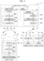
- FIG. 2 is a functional block diagram of a wireless communication system 1 according to a first embodiment.
- the controller 242 instructs the transmission data modulator 243 to transmit terminal transmission data.
- the controller 242 instructs the transmitter 244 to a transmission weight each transmission time read from the storage 241.
- the transmission data modulator 243 receives an instruction from the controller 242 and reads terminal transmission data from the data storage 23 as transmission data.
- the transmission data modulator 243 converts the read transmission data into parallel signals and then modulates the parallel signals.
- the transmitter 244 performs weighting of the modulated parallel signals using a transmission weight instructed from the controller 242 and generates a base station downlink signal transmitted from each of the antennas 25.
- the transmitter 244 transmits the generated base station downlink signals from the antennas 25 using MIMO.
- the terminal station 3 includes a data storage 31, a transmitter 32, and one or a plurality of antennas 33.
- the data storage 31 stores sensor data and the like.
- the transmitter 32 reads sensor data from the data storage 31 as terminal transmission data and wirelessly transmits a terminal uplink signal in which the read terminal transmission data has been set through the antennas 33.
- the transmission unit 32 transmits a signal according to, for example, Low Power Wide Area (LPWA).
- LPWA Low Power Wide Area
- the transmitter 32, as well as other terminal stations 3 may perform transmission according to time division multiplexing, Orthogonal Frequency Division Multiplexing (OFDM), MIMO, or the like.
- OFDM Orthogonal Frequency Division Multiplexing
- the base station 4 includes a plurality of antenna stations 41, a receiver 42, and a base station signal reception processor 43.
- Antenna station 41 converts base station downlink signal received from the mobile relay station 2 into an electric signal and outputs the electric signal to the receiver 42.
- the receiver 42 aggregates base station downlink signals received from the plurality of antenna stations 41.
- the receiver 42 includes a storage 421, a controller 422, and an adder 423.
- the storage 421 stores a reception weight for each reception time and transmission capacity information in advance.
- the transmission capacity information represents a transmission capacity of a downlink of each antenna station 41 for each reception time.
- a reception weight for each reception time is calculated on the basis of orbit information of the LEO satellite and a position of each antenna station 41.
- the controller 422 selects antenna stations 41 of a predetermined number in order of largest to smallest transmission capacity at each reception time by referring to the transmission capacity information stored in the storage 421.
- the number of antenna stations 41 that are selected is smaller than a total number of antenna stations 41 included in the base station 4.
- the controller 422 instructs the adder 423 to add reception signals of the selected antenna stations 41.
- the controller 422 reads a reception weight of each reception signal for each reception time from the storage 421 and instructs the read reception weight to the adder 423.
- the adder 423 multiplies a reception signal of each of antenna stations 41 instructed to be added from the controller 422 by a reception weight instructed from the controller 422 and adds and synthesizes reception signals multiplied by reception weights.
- the same reception weight may be used regardless of the reception time.
- the base station signal reception processor 43 demodulates and decodes a reception signal acquired by adding and synthesizing the reception signals using the adder 423, thereby acquiring terminal transmission data.
- the mobile relay station 2 accumulates terminal transmission data received from each terminal station 3 in the data storage 23. More specifically, each terminal station 3 acquires data detected by a sensor, which is not illustrated, provided outside or inside as required and writes the acquired data in the data storage 31.
- the transmitter 32 reads sensor data from the data storage 31 as terminal transmission data and wirelessly transmits a terminal uplink signal in which the read terminal transmission data is set from the antenna 33.
- the receiver 221 of the mobile relay station 2 receives a terminal uplink signal transmitted from each terminal station 3, and the terminal signal reception processor 222 demodulates and decodes the terminal uplink signal received by the receiver 221, thereby acquiring terminal transmission data.
- the data recorder 223 writes the terminal transmission data in the data storage 23.
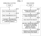
- FIG. 3 is a flowchart illustrating a process of the wireless communication system 1 of a case in which a base station downlink signals are transmitted from the mobile relay station 2.
- the controller 242 included in the base station communicator 24 of the mobile relay station 2 reads transmission weights corresponding to the current time from the storage 241 and gives an instruction of the transmission weights to the transmitter 244 (Step S111).
- the transmission data modulator 243 receives an instruction from the controller 242 and reads terminal transmission data accumulated in the data storage 23 as transmission data (Step S112).
- the transmission data modulator 243 encodes the read transmission data, performs parallel conversion of the encoded transmission data, and then modulates the converted data.
- the transmitter 244 performs weighting of the transmission data modulated by the transmission data modulator 243 using transmission weights instructed from the controller 242, thereby generating a base station downlink signal that is a transmission signal to be transmitted from each antenna 25.
- the transmitter 244 transmits each generated base station downlink signal from the antennas 25 using MIMO (Step S113).
- the mobile relay station 2 repeats the process from Step S111. In addition, the mobile relay station 2 may perform the process of Step S111 after the process of Step S112.
- Each antenna station 41 of the base station 4 outputs a reception signal acquired by converting the base station downlink signal received from the mobile relay station 2 into an electric signal to the receiver 42 (Step S121).
- the controller 422 selects some antenna stations 41 of a predetermined number having large transmission capacities at the current time among all the antenna stations 41 as a subset by referring to the transmission capacity information stored in the storage 421 (Step 122).
- the controller 422 instructs the adder 423 to use reception signals of the selected antenna stations 41 of the subset for reception.
- the controller 422 reads a reception weight corresponding to the current time from the storage 421 and gives an instruction of the read reception weight to the adder 423 (Step S123).
- the adder 423 selects a reception signal of each antenna station 41 instructed to be used for reception from the controller 422 and multiplies the selected reception signal by a reception weight instructed from the controller 422.
- the adder 423 adds reception signals that have been multiplied by reception weights (Step S124).
- the base station signal reception processor 43 demodulates the added reception signal and decodes the demodulated reception signal to acquire terminal transmission data (Step S125).
- the base station 4 repeats the process from Step S121.
- Step S113 the transmission data modulator 243 modulates transmission data of a serial signal, and the transmitter 244 transmits a base station downlink signal in which the modulated transmission data is set from the antenna 25.
- the controller 422 may generate such information as required and write the generated information in the storage 421.
- the storage 421 may store antenna stations 41 of a subset for each time or for each time frame in place of the transmission capacity information.
- Antenna stations 41 of a predetermined number are selected as a subset in order of largest to smallest transmission capacity on the basis of a transmission capacity of a downlink of each antenna station 41 for each time.
- the controller 422 reads information of the antenna stations 41 of the subset corresponding to the current time from the storage 421 in Step S122.
- the mobile relay station 2 may receive a base station uplink signal transmitted from the base station 4.
- a transmission capacity of an uplink between each antenna of the mobile relay station 2 and each antenna station 41 of the base station 4 at each time is calculated in advance on the basis of movement schedule information of the mobile relay station 2, information of the position of each antenna station 41 of the base station 4, and a frequency of wireless communication.
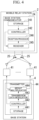
- FIG. 4 is a block diagram illustrating a configuration of the mobile relay station 2 and the base station 4 of a case in which the mobile relay station 2 receives a base station uplink signal from the base station 4.
- FIG. 4 only functional modules relating to transmission/reception of base station uplink signals are extracted and illustrated.
- the base station 4 includes a transmitter 44.
- the transmitter 44 includes a storage 441, a controller 442, a transmission data modulator 443, and a weight multiplicator 444.
- the storage 441 stores transmission capacity information and a transmission weight for each transmission time in advance.
- the transmission capacity information stored by the storage 441 represents a transmission capacity of an uplink between each antenna station 41 and the mobile relay station 2 for each transmission time.
- a transmission weight for each transmission time is calculated on the basis of orbit information of the LEO satellite and a position of each antenna station 41.
- the controller 442 selects antenna stations 41 of a predetermined number in order of largest to smallest transmission capacity of the uplink at each transmission time by referring to the transmission capacity information stored in the storage 441.
- the number of selected antenna stations 41 is smaller than a total number of the antenna stations 41 included in the base station 4.
- the controller 442 instructs the transmission data modulator 443 to transmit a terminal uplink signal using the antenna station 41 selected for each transmission time.
- the controller 442 reads a transmission weight of each antenna station 41 for each transmission time from the storage 441 and gives an instruction of the read transmission weight to the weight multiplicator 444.
- the transmission data modulator 443 encodes transmission data to be transmitted to the mobile relay station 2.
- the transmission data modulator 443 converts the encoded transmission data into parallel signals to be transmitted from each antenna station 41 instructed from the controller 442 and then modulates the parallel signals.
- the weight multiplicator 444 performs weighting of the modulated parallel signals using transmission weights instructed from the controller 442 and generates a base station uplink signal transmitted from each of antenna stations 41.
- the weight multiplicator 444 outputs the generated base station uplink signals to a corresponding antenna stations 41.
- Each of the antenna stations 41 selected by the controller 442 wirelessly transmits the base station uplink signal.
- the base station communicator 24 of the mobile relay station 2 includes a storage 241, a controller 242, a receiver 245, and a reception processor 246.
- the storage 241 stores a reception weight of the base station uplink signal, which is received by each antenna 25, for each reception time in advance.
- the reception weight for each reception time is calculated on the basis of the orbit information of the LEO satellite and the position of each antenna station 41. In addition, a constant reception weight may be used regardless of the reception time.
- the controller 242 reads a reception weight of each antenna 25 for each reception time from the storage 241 and gives an instruction of the read reception weight to the receiver 245.
- the receiver 245 receives a base station uplink signal using each antenna 25 and performs weighting of the reception signal received by each antenna 25 using a reception weight instructed from the controller 242 and then adds and synthesizes the reception signals.
- the reception processor 246 demodulates and decodes the reception signal added and synthesized by the receiver 245, thereby acquiring transmission data transmitted by the base station 4.
- FIG. 5 is a flowchart illustrating a process of the wireless communication system 1 of a case in which a base station uplink signal is transmitted from the base station 4.
- the controller 442 of the base station 4 selects antenna stations 41 of a predetermined number in order of largest to smallest transmission capacity of the uplink at the current time as a subset by referring to the transmission capacity information stored in the storage 441 (Step S211).
- the controller 442 instructs the transmission data modulator 443 to transmit terminal uplink signals using the antenna stations 41 of the subset.
- the controller 442 reads a transmission weight of each of the antenna stations 41 of the subset corresponding to the current time from the storage 441 and gives an instruction of the read transmission weight to the weight multiplicator 444 (Step S212).
- the transmission data modulator 443 encodes transmission data transmitted to the mobile relay station 2, converts the encoded transmission data into parallel signals to be transmitted from each of the antenna stations 41 of the subset, and then modulates the parallel signals.
- the weight multiplicator 444 performs weighting of the modulated parallel signals using a transmission weight instructed from the controller 442 and generates a base station uplink signal to be transmitted from each of the antenna stations 41 of the subset.
- the weight multiplicator 444 outputs the generated base station uplink signal to a corresponding antenna station 41.
- Each of the antenna stations 41 of the subset wirelessly transmits the base station uplink signal (Step S213).
- the controller 442 may generate such information as required and write the generated information in the storage 441.
- the base station 4 may transmit information of a transmission weight and a reception weight of each antenna 25 for each time to the mobile relay station 2 using a base station uplink signal.
- the base station 4 performs a process represented in FIG. 6 in place of the processes of Step S121 to Step S122 represented in FIG. 3 .
- FIG. 6 is a flowchart illustrating the process of the base station 4 according to this embodiment.
- the base station 4a wirelessly communicates with the mobile relay station 2an that is described to be a communication destination at the current time in the communication destination relay station information. For example, in a time frame in which transmission capacity C1 > transmission capacity C2, the base station 4a communicates with the mobile relay station 2a-1, and, at a timing at which transmission capacity C1 ⁇ transmission capacity C2, the base station 4a switches the communication destination from the mobile relay station 2a-1 to the mobile relay station 2a-2.
- controller 442a may generate information stored in the storage 421a of the base station 4a as required. Furthermore, the controller 442a may generate the information stored in the storage 441a of the base station 4a as required. In addition, the base station 4a may transmit the information stored in the storage 241a to the mobile relay station 2a using the base station uplink signal.
- the process of the first or second embodiment may be performed between the base station 4a and the mobile relay station 2a that is the communication destination.
- selection and switching of an antenna station performing reception for a base station are performed.
- selection and switching of an antenna performing transmission are performed also in a mobile relay station.
- this embodiment will be described with focusing on differences from the first embodiment.
- the mobile relay station 2b includes one or more antennas 21, a terminal communicator 22, a data storage 23, a base station communicator 24, and a plurality of antennas 25.
- the mobile relay station 2b includes three or more antennas 25, and selection and switching of antennas 25 are performed at the time of performing wireless communication with the base station 4b using MIMO will be described.
- the mobile relay station 2b uses two antennas 25 at the time of wirelessly communicating with the base station 4b using MIMO, two antennas 25 among three or more antennas 25 included in the mobile relay station 2b are selected.
- the mobile relay station 2b performs switching of antennas 25 such that communication is performed using the two antennas 25 that have been selected.
- the base station communicator 24b transmits terminal transmission data to the base station 4b.
- the base station communicator 24b includes a storage 241b, a controller 242b, a transmission data modulator 243, and a transmitter 244.
- the storage 241b stores in advance a transmission weight for each transmission time of a base station downlink signal transmitted from each antenna 25.
- the storage 241b stores information of used antennas 25 (hereinafter, referred to as "mobile relay station used antenna information") for each time.
- the mobile relay station used antenna information for example, is information in which the number of used antennas 25 and a time are associated with each other.
- the controller 242b determines a combination of antennas 25, which are included in the mobile relay station 2b, used for communication between the mobile relay station 2b and the base station 4b and antenna stations 41, which are included in the base station 4b, used for communication between the mobile relay station 2b and the base station 4b (hereinafter, referred to as "a combination of used antennas") for each time on the basis of a channel capacity (transmission capacity) between the mobile relay station 2b and the base station 4b.
- the combination of used antennas described here is a combination of the number of antennas 25 and antenna stations 41 used for communication between the mobile relay station 2b and the base station 4b. More specifically, the combination of used antennas is a combination of the number of antennas 25 and the number of antenna stations 41 used at each time.
- the controller 242b selects antennas 25 to be used for communication with the base station 4b among antennas 25 included in the mobile relay station 2b in accordance with the determined combination of used antennas for each time.
- the controller 242b performs switching among a plurality of antennas 25 such that communication is performed using the selected antennas 25.
- a switch may be used for switching among antennas 25, a switch may be used.
- the controller 242b instructs the transmission data modulator 243 to transmit the terminal transmission data.
- the controller 242b gives an instruction of a transmission weight for each transmission time that has been read from the storage 241 to the transmitter 244.
- the base station 4b includes a plurality of antenna stations 41, a receiver 42b, and a base station signal reception processor 43.
- the receiver 42b aggregates base station downlink signals received from a plurality of antenna stations 41.
- the receiver 42b aggregates base station downlink signals received from antenna stations 41 corresponding to a number notified from the mobile relay station 2b in advance.
- the receiver 42b includes a storage 421b, a controller 422b, and an adder 423.
- the storage 421b stores information of used antenna stations 41 (hereinafter, referred to as "base station used antenna information") for each time, transmission capacity information, and a reception weight for each reception time in advance.
- the base station used antenna information is information in which the number of antenna stations 41 to be used and a time are associated with each other.
- the controller 422b selects antenna stations 41 to be used for communication with the mobile relay station 2b among antenna stations 41 included in the base station 4b on the basis of the base station used antenna information and the transmission capacity information notified from the mobile relay station 2b. For example, the controller 422b selects antenna stations 41 corresponding to the number included in the base station used antenna information in order of largest to smallest transmission capacity at each reception time.
- the controller 422b instructs the adder 423 to add reception signals of the selected antenna stations 41.
- the controller 422b reads a reception weight of each reception signal for each reception time from the storage 421 and gives an instruction of the read reception weight to the adder 423.
- FIG. 12 is a diagram illustrating an example of arrangement of antennas 25 arranged in the mobile relay station 2b.
- M represents a total number of antennas 25 arranged in the mobile relay station 2b
- N represents the number of antennas 25 used for communication with the base station 4b in the mobile relay station 2b.
- an antenna 25 used for communication with the base station 4b is denoted by 25-1
- an antenna 25 not used for communication with the base station 4b is denoted by 25-2.
- FIG. 12(A) illustrates arrangement positions of antennas 25 of a case in which a total number of antennas 25 arranged in the mobile relay station 2b is 2, and the number of antennas 25 used by the mobile relay station 2b is 2.
- FIG. 12(B) illustrates arrangement positions of antennas 25 of a case in which a total number of antennas 25 arranged in the mobile relay station 2b is 3, and the number of antennas 25 used by the mobile relay station 2b is 2.
- FIG. 12(C) illustrates arrangement positions of antennas 25 of a case in which a total number of antennas 25 arranged in the mobile relay station 2b is 4, and the number of antennas 25 used by the mobile relay station 2b is 2.
- FIG. 12(D) illustrates arrangement positions of antennas 25 of a case in which a total number of antennas 25 arranged in the mobile relay station 2b is 6, and the number of antennas 25 used by the mobile relay station 2b is 2.
- the antennas 25 are disposed at the interval of 2 ⁇ /M.
- M is a total number of antennas 25.
- FIG. 13 illustrates a result of analysis of a channel capacity at the time of performing MIMO communication between the mobile relay station 2b and the base station 4b.
- the horizontal axis represents time
- the vertical axis represents a channel capacity.
- FIG. 13(A) illustrates a result of analysis of a channel capacity in the case of the arrangement of antennas 25 illustrated in FIG. 12(A)
- FIG. 13(B) illustrates a result of analysis of a channel capacity in the case of the arrangement of antennas 25 illustrated in FIG. 12(B)
- FIG. 13(C) illustrates a result of analysis of a channel capacity in the case of the arrangement of antennas 25 illustrated in FIG. 12(C) .
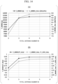
- FIG. 14 is a diagram illustrating a result of analysis of a MIMO application time and a channel capacity average value per week for each number of antennas.
- a time frame in which the channel capacity is above "the channel capacity (C1) at time of complete separation of signals” in Fig. 13 is defined as an MIMO applicable time.
- SISO is at time of transmission using one antenna
- MIMO is at time of transmission using two antennas
- transmission power of one antenna is assumed to be constant.
- FIG. 15 is a flowchart illustrating a process of the mobile relay station 2b determining a combination of used antennas.
- a process of the mobile relay station 2b determining a combination of antennas to be used for a visualization time before the mobile relay station 2b starts communication for transmitting data acquired from the terminal station 3 to the base station 4b will be described.
- the visualization time may be calculated on the basis of the orbit information of the mobile relay station 2b and the position information of the base station 4b or may be set in advance.
- the mobile relay station 2b determines the number of antennas 25 used for transmission in the mobile relay station 2b. In accordance with this, a combination of used antennas for which the transmission capacity becomes higher can be determined. As a result, communication that is more efficient than that according to each embodiment described above can be performed.
- the mobile relay station 2b includes a base station communicator 24b.
- the base station communicator 24b includes a storage 241b, a controller 242b, a receiver 245, and a reception processor 246.
- the receiver 245 of the mobile relay station 2b receives the base station uplink signal using the antennas 25 selected by the controller 242b (Step S632).
- the controller 242b reads a reception weight of each antenna 25 corresponding to the current time from the storage 241b and gives an instruction of the read reception weight to the receiver 245 (Step S633).
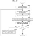
- the controller 242b determines whether or not the current time t is a time T (Step S636). In a case in which the current time t is the time T (Step S636 - Yes), the mobile relay station 2b ends the process illustrated in FIG. 25 .
- Step S636 - No the controller 242b selects antennas 25 to be used for reception according to the current time by referring to the time again (Step S637).
- the controller 242b may not perform switching of the antennas 25. Thereafter, the mobile relay station 2b performs a process of Step S632 and subsequent steps.
- the controller 242b may be configured to select antennas 25 used for communication with the base station 4b using the transmission capacity information.
- transmission capacity information is additionally stored in the storage 241b.
- the transmission capacity information stored by the storage 241b represents a transmission capacity of the uplink of each antenna 25 for each reception time.
- the controller 242b selects antennas 25 corresponding to the determined number in order of largest to smallest transmission capacity at each reception time by referring to the transmission capacity information stored in the storage 241b.
- the configuration of the wireless communication system according to this embodiment is similar to the configuration illustrated in FIG. 22 .
- a difference in the process between the configuration of this embodiment and the configuration illustrated in FIG. 22 is in that the mobile relay station 2b determines a combination of used antennas in real time and receives a base station uplink signal in the configuration illustrated in FIG. 22 .
- the mobile relay station 2b performs the processes of Steps S501 and S502 illustrated in FIG. 15 in advance and stores results of the processes in the storage 241b.
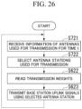
- FIG. 26 is a flowchart illustrating a process of the base station 4b selecting antenna stations used for transmission and transmitting a base station uplink signal in real time.
- Each antenna station 41 of the base station 4b receives information of a transmission antenna of a time t transmitted from the mobile relay station 2b (Step S721).
- the transmission antenna information of the time t is information that represents the number of antenna stations 41 used by the base station 4b for transmission of a base station uplink signal at the time t.
- the controller 442b selects antenna stations 41 to be used for transmission at the time t among all the antenna stations 41 as a subset by referring to the information of transmission antennas and the transmission capacity information received through the antenna station 41 (Step S722). Thereafter, the base station 4b performs the process of Step S622 and subsequent steps. In accordance with this, the base station 4b receives the information of transmission antennas of each time as required and selects antenna stations 41 on the basis of the latest information of transmission antennas.
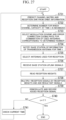
- the controller 242b determines a number x(t) of a combination of used antennas that maximizes a channel capacity C x at a time t on the basis of Equation (2) described above and a number for each combination of used antennas stored in the storage 241b (Step S732).
- the controller 242b stores information of the number of antennas 25 in the combination of used antennas associated with the determined number x(t) in the storage 241b as mobile relay station used antenna information.
- the controller 242b selects a modulation scheme and an error correction coding rate in the combination of used antennas associated with the determined number x(t) (Step S733).
- the controller 242b causes the storage 241b to store information of the modulation scheme and the error correction coding rate in the combination of used antennas associated with the determined number x(t).
- the controller 242b notifies the base station 4b of the information of transmission antennas of the time t through an antenna 25 (Step S734).
- the controller 242b selects antennas 25 used for reception at the time t by referring to mobile relay station used antenna information stored in the storage 241b (Step S735).
- the controller 242b performs switching of antennas 25 such that a base station uplink signal is received by the selected antennas 25.
- the receiver 245 of the mobile relay station 2b receives the base station uplink signal using the antennas 25 selected by the controller 242b (Step S736).
- the controller 242b reads a reception weight of each antenna 25 corresponding to the current time from the storage 241b and gives an instruction of the read reception weight to the receiver 245 (Step S637).
- the receiver 245 performs weighting of a reception signal received by each antenna 25 selected by the controller 242b using a reception weight instructed from the controller 242b and then performs addition and synthesis of the reception signals (Step S738).
- the reception processor 246 demodulates and decodes the reception signal acquired by performing addition and synthesis using the receiver 245 and acquires transmission data transmitted by the base station 4b (Step S739).
- the controller 242b determines whether or not the current time t is a time T (Step S740). In a case in which the current time t is the time T (Step S740 - Yes), the mobile relay station 2b ends the process illustrated in FIG. 27 .
- Step S740 - No the controller 242b checks the current time t by referring to the time again (Step S741). Thereafter, the mobile relay station 2b performs the process of Step S731 and subsequent steps.
- the controller 242b may be configured to select antennas 25 used for communication with the base station 4b using the transmission capacity information.
- transmission capacity information is additionally stored in the storage 241b.
- the controller 242b selects antennas 25 corresponding to the determined number in order of largest to smallest transmission capacity at each reception time by referring to the transmission capacity information stored in the storage 241b.
- FIG. 28 is a block diagram illustrating a configuration of the mobile relay station 2c and the base station 4b of a case in which the mobile relay station 2c receives a base station uplink signal from the base station 4b.
- the antenna quantity determining station 5 illustrated in FIG. 28 performs the process represented in the sixth embodiment. In FIG. 28 , only functional modules relating to transmission/reception of base station uplink signals are extracted and illustrated.
- the process of determining a combination of used antennas illustrated in FIG. 20 is performed by the antenna quantity determining station 5, and information of used antennas for a visualization time is stored in each of the mobile relay station 2c and the base station 4b.
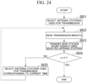
- the process performed in a case in which the base station 4b transmits a base station uplink signal is similar to that illustrated in FIG. 24 .
- a process performed in a case in which the mobile relay station 2c receives a base station uplink signal from the base station 4b is similar to that illustrated in FIG. 25 .
- the configuration of the wireless communication system according to this embodiment is similar to the configuration illustrated in FIG. 27 .
- a difference in the process between the configuration of this embodiment and the configuration illustrated in FIG. 27 is in that the antenna quantity determining station 5 determines a combination of used antennas in real time in the configuration illustrated in FIG. 27 .
- the antenna quantity determining station 5 performs the processes of Steps S801 and S802 illustrated in FIG. 20 in advance and stores results of the processes in the storage 51.
- FIG. 29 is a flowchart illustrating a process of the mobile relay station 2c receiving a base station uplink signal.
- a visualization time t 1
- reference signs similar to those illustrated in FIG. 27 are assigned to the same processes as those illustrated in FIG. 27 , and description thereof will be omitted.
- the terminal communicator 22c outputs the received transmission information to a base station communicator 24c.
- a controller 242c of the base station communicator 24c stores the information of a combination of used antennas and the information of a modulation scheme and an error correction coding rate for the combination of used antennas that are included in the acquired transmission information in a storage 241c.
- the controller 242c notifies the base station 4b of the information of the number of antennas used for reception for the time t in the information of the combination of used antennas through the antenna 25 (Step S922). Thereafter, the mobile relay station 2c performs the process of Step S735 and subsequent steps.
- the process of the base station 4b is similar to that illustrated in FIG. 26 .
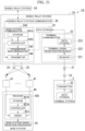
- FIG. 31 is a block diagram illustrating a configuration of the wireless communication system 1d according to the eighth embodiment.
- the same reference signs will be assigned to the same parts as those of the wireless communication system 1b according to the fourth embodiment illustrated in FIG. 11 , and description thereof will be omitted.
Landscapes
- Engineering & Computer Science (AREA)
- Computer Networks & Wireless Communication (AREA)
- Signal Processing (AREA)
- Physics & Mathematics (AREA)
- Astronomy & Astrophysics (AREA)
- Aviation & Aerospace Engineering (AREA)
- General Physics & Mathematics (AREA)
- Mobile Radio Communication Systems (AREA)
Abstract
Description
- The present invention relates to a wireless communication system, a wireless communication apparatus, and a wireless communication method.
- Priority is claimed on International Patent Application No.
PCT/JP2020/022650, filed June 9, 2020 - MIMO communication is one of communication schemes performing highspeed and high-reliability wireless communication using a plurality of antennas. In this MIMO communication, there is a technology for selecting a subset of reception antennas on the basis of channel state information (CSI) such that a channel capacity is maximized (for example, see Non Patent Document 1). In accordance with this, a transmission capacity that is close to an optimal value is established at a low cost. In addition, there is a technology for selecting a subset of antennas, which are used for wireless communication, among a plurality of antennas using CSI that has been fed back (for example, see Non Patent Document 2).
-
- [Non Patent Document 1]
Alexei Gorokhov, Dhananjay A. Gore, and Arogyaswami J. Paulraj, "Receive Antenna Selection for MIMO Spatial Multiplexing: Theory and Algorithms", IEEE Transactions on Signal Processing, Vol. 51, No. 11, 2003, p. 2796 - 2807 - [Non Patent Document 2]
Shahab Sanayei and Aria Nosratinia, "Antenna Selection in MIMO Systems", IEEE Communications magazine, Vol. 42, No. 10, 2004, p. 68 - 73 - [Non Patent Document 3]
C. Kato, M. Nakadai, D. Goto, H. Shibayama and F. Yamashita, "Channel Capacity Analysis of Satellite MIMO System Depending on the Orbital Altitude," in 37th AIAA International Communication Satellite Systems Conference (ICSSC 2019), Oct. 2019. - In a case in which a wireless communication apparatus is mounted on a moving body, CSI changes in accordance with movement of the wireless communication apparatus. In the technologies disclosed in
Non Patent Document Non Patent Document 3 shows that MIMO can be applied to satellites by building a communication channel model with orbit conditions of a satellite that is a moving body and it is analytically derived that a communication channel capacity can be controlled in accordance with a distance between transmission antennas or reception antennas, there is periodicity in changes of the channel capacity over time in a satellite communication channel, and a time frame in which signals completely interfere with each other in accordance with an influence of the periodicity occurs, whereby there are problems in that the communication capacity decreases, and the stability of the communication channel deteriorates. - In consideration of the situations described above, an object of the present invention is to provide a wireless communication system, a wireless communication apparatus, and a wireless communication method capable of performing wireless communication with high communication quality while a load is reduced even in a case in which the wireless communication apparatus is moving.
- According to one aspect of the present invention, there is provided a wireless communication system including: a first wireless communication apparatus; and a second wireless communication apparatus, in which the first wireless communication apparatus includes: one or more first antennas; and a first communicator configured to wirelessly communicate with the second wireless communication apparatus using the one or more first antennas, the second wireless communication apparatus includes: one or more second antennas; and a second communicator configured to wirelessly communicate with the first wireless communication apparatus using the one or more second antennas, the wireless communication system further including: a controller configured to perform control to change one or both of first antennas wirelessly communicating with the second wireless communication apparatus among the one or more first antennas of a plurality of first wireless communication apparatuses or second antennas wirelessly communicating with the first wireless communication apparatus among a plurality of second antennas of the second wireless communication apparatus for maximizing communication quality on the basis of the communication quality for each time between first antenna and second antenna calculated using a position of the one or more second antennas and movement schedule information representing a position of the first wireless communication apparatus for each time.
- According to one aspect of the present invention, there is provided a wireless communication apparatus including: one or more antennas; a communicator configured to wirelessly communicate with a communication destination apparatus using the one or more antennas; and a controller configured to perform control to change one or both of antennas wirelessly communicating with the wireless communication apparatus among antennas of a plurality of the communication destination apparatuses or antennas wirelessly communicating with the communication destination apparatus among a plurality of the antennas of the wireless communication apparatus for maximizing communication quality on the basis of the communication quality for each time between the one or more antennas and the antennas of a plurality of the communication destination apparatuses calculated using a position of the one or more antennas and movement schedule information representing a position of the communication destination apparatus for each time.
- According to one aspect of the present invention, there is provided a wireless communication apparatus in a wireless communication system including a plurality of the wireless communication apparatuses, the wireless communication apparatus including: one or more antennas; a communicator configured to wirelessly communicate with a communication destination apparatus using the one or more antennas; and a controller configured to perform control of the communicator to transmit a wireless signal to the communication destination apparatus at a time at which the one or more antennas of wireless communication apparatus are selected as a communication destination of the communication destination apparatus for maximizing communication quality on the basis of communication quality for each time between antenna of each of the plurality of the wireless communication apparatuses and antennas of the communication destination apparatus calculated using a position of antennas of the communication destination apparatus and movement schedule information representing a position of each of the plurality of the wireless communication apparatuses for each time.
- According to one aspect of the present invention, there is provided a wireless communication method executed by a wireless communication system including a first wireless communication apparatus and a second wireless communication apparatus, the wireless communication method including: wirelessly communicating with the second wireless communication apparatus using one or more first antennas by the first wireless communication apparatus; wirelessly communicating with the first wireless communication apparatus using one or more second antennas by the second wireless communication apparatus; and performing control to change one or both of first antennas wirelessly communicating with the second wireless communication apparatus among the one or more first antennas of a plurality of first wireless communication apparatuses or second antennas wirelessly communicating with the first wireless communication apparatus among a plurality of second antennas of the second wireless communication apparatus for maximizing communication quality on the basis of the communication quality for each time between first antenna and second antenna calculated using a position of the one or more second antennas and movement schedule information representing a position of the first wireless communication apparatus for each time by a controller.
- According to one aspect of the present invention, there is provided a wireless communication method executed by a wireless communication apparatus, the wireless communication method including: wirelessly communicating with a communication destination apparatus using one or more antennas; and performing control to change one or both of antennas wirelessly communicating with the wireless communication apparatus among antennas of a plurality of the communication destination apparatuses or antennas wirelessly communicating with the communication destination apparatus among a plurality of the antennas of the wireless communication apparatus for maximizing communication quality on the basis of the communication quality for each time between the one or more antennas and the antennas of a plurality of the communication destination apparatuses calculated using a position of the one or more antennas and movement schedule information representing a position of the communication destination apparatus for each time.
- According to one aspect of the present invention, there is provided a wireless communication method executed by a wireless communication apparatus in a wireless communication system including a plurality of wireless communication apparatuses, the wireless communication method including: wirelessly communicating with a communication destination apparatus using one or more antennas; a performing control to perform control of the communicator to transmit a wireless signal to the communication destination apparatus at a time at which the one or more antennas of wireless communication apparatus are selected as a communication destination of the communication destination apparatus for maximizing communication quality on the basis of communication quality for each time between antenna of each of the plurality of the wireless communication apparatuses and antennas of the communication destination apparatus calculated using a position of antennas of the communication destination apparatus and movement schedule information representing a position of each of the plurality of the wireless communication apparatuses for each time.
- According to the present invention, wireless communication can be performed with high communication quality while suppressing a load even in a case in which a wireless communication apparatus moves.
-
-
FIG. 1 is a diagram illustrating an overview of a wireless communication system according to a first embodiment of the present invention. -
FIG. 2 is a functional block diagram of the wireless communication system according to this embodiment. -
FIG. 3 is a flowchart illustrating a process of the wireless communication system according to this embodiment. -
FIG. 4 is a functional block diagram of a mobile relay station and a base station according to this embodiment. -
FIG. 5 is a flowchart illustrating a process of the wireless communication system according to this embodiment. -
FIG. 6 is a flowchart illustrating a process of a base station according to a second embodiment. -
FIG. 7 is a diagram illustrating an overview of a wireless communication system according to a third embodiment. -
FIG. 8 is a configuration diagram of the wireless communication system according to the third embodiment. -
FIG. 9 is a flowchart illustrating a process of the wireless communication system according to this embodiment. -
FIG. 10 is a functional block diagram of a mobile relay station and a base station according to this embodiment. -
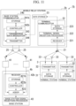
FIG. 11 is a diagram illustrating an overview of a wireless communication system according to a fourth embodiment. -
FIG. 12 is a diagram illustrating an example of arrangement of antennas arranged in a mobile relay station. -
FIG. 13 is a diagram illustrating a result of analysis of a channel capacity at the time of performing MIMO communication between a mobile relay station and a base station. -
FIG. 14 is a diagram illustrating a result of analysis of a MIMO application time and a channel capacity average value per week for each number of antennas. -
FIG. 15 is a flowchart illustrating a process of a mobile relay station determining a combination of antennas to be used. -
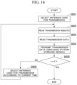
FIG. 16 is a flowchart illustrating a process of transmitting a base station downlink signal from a mobile relay station. -
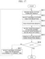
FIG. 17 is a flowchart illustrating a process of a base station receiving a base station downlink signal from a mobile relay station. -
FIG. 18 is a flowchart illustrating a process of a mobile relay station determining a combination of used antennas and transmitting a base station downlink signal. -
FIG. 19 is a diagram illustrating an overview of a wireless communication system according to a sixth embodiment. -
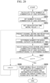
FIG. 20 is a flowchart illustrating a process of an antenna quantity determining station determining a combination of used antennas. -
FIG. 21 is a flowchart illustrating a process of an antenna quantity determining station determining a combination of used antennas. -
FIG. 22 is a flowchart illustrating a process of transmitting a base station downlink signal from a mobile relay station. -
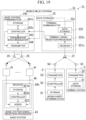
FIG. 23 is a block diagram illustrating a configuration of a mobile relay station and a base station of a case in which the mobile relay station receives a base station uplink signal from the base station. -
FIG. 24 is a flowchart illustrating a process of transmitting a base station uplink signal from a base station. -
FIG. 25 is a flowchart illustrating a process of a mobile relay station receiving a base station uplink signal from a base station. -
FIG. 26 is a flowchart illustrating a process of a base station selecting antenna stations used for transmission and transmitting a base station uplink signal in real time. -
FIG. 27 is a flowchart illustrating a process of a mobile relay station determining a combination of used antennas and receiving a base station uplink signal. -
FIG. 28 is a block diagram illustrating a configuration of a mobile relay station and a base station of a case in which the mobile relay station receives a base station uplink signal from the base station. -
FIG. 29 is a flowchart illustrating a process of a mobile relay station receiving a base station uplink signal. -
FIG. 30 is a diagram illustrating an overview of a wireless communication system according to an eighth embodiment. -
FIG. 31 is a configuration diagram of the wireless communication system according to the eighth embodiment. - Hereinafter, embodiments of the present invention will be described in detail with reference to the drawings.
-
FIG. 1 is a diagram illustrating an overview of awireless communication system 1 according to a first embodiment. Thewireless communication system 1 includes amobile relay station 2, aterminal station 3, and abase station 4. The number of each of themobile relay stations 2, theterminal stations 3, and thebase stations 4 included in thewireless communication system 1 is arbitrary, but it is assumed that there are a large number ofterminal stations 3. - The
mobile relay station 2 is an example of a wireless communication apparatus which is mounted on a moving body, and an area in which themobile relay station 2 can perform communication moves with the passage of time. Themobile relay station 2 is provided in, for example, a low Earth orbit (LEO) satellite. Theterminal station 3 and thebase station 4 are installed on the Earth such as on the ground or the sea. Theterminal station 3 is, for example, an IoT terminal. Theterminal station 3 collects data such as environmental data detected by a sensor and wirelessly transmits the data to themobile relay station 2. Themobile relay station 2 receives data transmitted from each of the plurality ofterminal stations 3 through wireless signals and wirelessly transmits the received data to thebase station 4 while moving over the Earth. Thebase station 4 receives the data collected by theterminal station 3 from themobile relay station 2. - It is conceivable to use a relay apparatus mounted on an unmanned aerial vehicle such as a geostationary satellite, a drone or a high altitude platform station (HAPS) as a mobile relay station. However, in the case of a relay station mounted on a geostationary satellite, the coverage area (footprint) on the ground is wide, but a link budget for IoT terminals installed on the ground is considerably small due to a high altitude. On the other hand, in the case of a relay station mounted on a drone or a HAPS, the link budget is high, but the coverage area is narrow. Furthermore, drones require batteries and HAPS require solar panels. In the present embodiment, the
mobile relay station 2 is mounted on a LEO satellite. Therefore, in addition to keeping the link budget within a limit, the LEO satellite has no air resistance and consumes less fuel because it orbits outside the atmosphere. In addition, the footprint is also large as compared to the case where a relay station is mounted on a drone or a HAPS. - However, the
mobile relay station 2 mounted on the LEO performs communication while moving at a high speed, and thus the relay station mounted on the LEO has a link budget smaller than that of a case in which a relay station is mounted on a drone or a HAPS. Thus, thebase station 4 according to the present embodiment receives a wireless signal from themobile relay station 2 using a plurality ofantenna stations 41. InFIG. 1 , fourantenna stations 41 included in thebase station 4 are denoted as antenna stations 41-1, 41-2, 41-3, and 41-4. In accordance with a diversity effect of communication and a beam forming effect according to use of the plurality ofantenna stations 41, the communication quality is improved, and the transmission capacity can be raised. - The plurality of
antenna stations 41 included in thebase station 4 are disposed at positions separated from each other such that an arrival angle difference between signals from the plurality of antennas of themobile relay station 2 is large. By disposing theantenna stations 41 at positions separated from each other, phase differences occur in wireless signals received from themobile relay station 2 by theantenna stations 41. In this way, since theantenna stations 41 are installed at positions geographically separated from each other, channel states between themobile relay station 2 and theantenna stations 41 are different from each other, and themobile relay station 2 move at high speed, and thus the channel states change over time. - Also, when a channel state changes in accordance with movement of the
mobile relay station 2, in order to cause themobile relay station 2 and thebase station 4 to perform communication using as high a transmission capacity as possible, a transmission capacity of each antenna of themobile relay station 2 and eachantenna station 41 of thebase station 4 at each time is calculated in advance in the present embodiment. This transmission capacity at each time is calculated on the basis of movement schedule information of themobile relay station 2, information of a position of eachantenna station 41, and a frequency of wireless communication. The movement schedule information is information that represents a position, a speed, and a movement direction of themobile relay station 2 at each time. In the present embodiment, as the movement schedule information, orbit information of a LEO satellite mounted on themobile relay station 2 is used. The orbit information is information from which a position, a speed, a movement direction, and the like of a LEO satellite at an arbitrary time can be acquired. A slant range that is a distance between antennas is acquired from the position of the antenna of themobile relay station 2 and the position of theantenna station 41 of thebase station 4. The position of the antenna of themobile relay station 2 may be a position of the LEO satellite acquired from orbit information or a position deviating from the position of the LEO satellite by a predetermined distance and a predetermined direction. In addition, a Doppler shift amount is acquired using a frequency and a speed of the LEO satellite. For a channel between the LEO satellite and theantenna station 41 of thebase station 4, an open environment is assumed. For this reason, an influence of multi-path fading occurring from reflected waves according to an obstacle can be ignored, and the channel becomes a channel in which a direct wave is dominant. In accordance with this, CSI such as a damping coefficient and a phase difference can be assumed to be uniquely determined on the basis of slant range information between the LEO satellite and theantenna station 41 of thebase station 4. As above, a channel capacity between transmission/reception antennas is calculated using Shannon's theorem from an SNR calculated on the basis of a slant range and a Doppler shift amount and a channel matrix acquired on the basis of a slant range between the antenna of themobile relay station 2 and theantenna station 41. - Then, the
base station 4 is caused to store a transmission capacity of eachantenna station 41 at each time. A transmission capacity is a channel capacity of a downlink calculated in advance as described above. Thebase station 4 uses a data series of wireless signals received byantenna stations 41 of a predetermined number having large transmission capacities from themobile relay station 2 at each time for a reception process. For example, thebase station 4 performs a reception process using wireless signals received by antenna stations 41-1 and 41-2 at a time t1 and performs a reception process using wireless signals received by antenna stations 41-3 and 41-4 at a time t2. - A configuration of each apparatus will be described.
FIG. 2 is a functional block diagram of awireless communication system 1 according to a first embodiment. - The
mobile relay station 2 includes one ormore antennas 21, aterminal communicator 22, adata storage 23, abase station communicator 24, and one ormore antennas 25. In the present embodiment, an example of a case where themobile relay station 2 includes a plurality ofantennas 25 and wirelessly communicates with thebase station 4 using Multiple Input Multiple Output (MIMO) will be described. - The
terminal communicator 22 includes areceiver 221, a terminalsignal reception processor 222, and adata recorder 223. Thereceiver 221 receives a terminal uplink signal transmitted from eachterminal station 3 using the one ormore antennas 21. The terminalsignal reception processor 222 performs a process of receiving a terminal uplink signal. In the reception process, the terminal uplink signal received by thereceiver 221 is demodulated and decoded, and terminal transmission data transmitted by theterminal station 3 is acquired. Thedata recorder 223 writes the terminal transmission data acquired using the reception process into thedata storage 23. - The
base station communicator 24 transmits terminal transmission data to thebase station 4. Thebase station communicator 24 includes astorage 241, acontroller 242, atransmission data modulator 243, and atransmitter 244. - The
storage 241 stores in advance a transmission weight for each transmission time of a base station downlink signal transmitted from eachantenna 25. The transmission weight for each transmission time is calculated on the basis of orbit information of the LEO satellite and the position of eachantenna station 41. A constant transmission weight may be used regardless of the transmission time. - The
controller 242 instructs the transmission data modulator 243 to transmit terminal transmission data. In addition, thecontroller 242 instructs thetransmitter 244 to a transmission weight each transmission time read from thestorage 241. Thetransmission data modulator 243 receives an instruction from thecontroller 242 and reads terminal transmission data from thedata storage 23 as transmission data. Thetransmission data modulator 243 converts the read transmission data into parallel signals and then modulates the parallel signals. Thetransmitter 244 performs weighting of the modulated parallel signals using a transmission weight instructed from thecontroller 242 and generates a base station downlink signal transmitted from each of theantennas 25. Thetransmitter 244 transmits the generated base station downlink signals from theantennas 25 using MIMO. - The
terminal station 3 includes adata storage 31, atransmitter 32, and one or a plurality ofantennas 33. Thedata storage 31 stores sensor data and the like. Thetransmitter 32 reads sensor data from thedata storage 31 as terminal transmission data and wirelessly transmits a terminal uplink signal in which the read terminal transmission data has been set through theantennas 33. Thetransmission unit 32 transmits a signal according to, for example, Low Power Wide Area (LPWA). Further, thetransmitter 32, as well asother terminal stations 3, may perform transmission according to time division multiplexing, Orthogonal Frequency Division Multiplexing (OFDM), MIMO, or the like. - The
base station 4 includes a plurality ofantenna stations 41, areceiver 42, and a base stationsignal reception processor 43.Antenna station 41 converts base station downlink signal received from themobile relay station 2 into an electric signal and outputs the electric signal to thereceiver 42. Thereceiver 42 aggregates base station downlink signals received from the plurality ofantenna stations 41. Thereceiver 42 includes astorage 421, acontroller 422, and anadder 423. - The
storage 421 stores a reception weight for each reception time and transmission capacity information in advance. The transmission capacity information represents a transmission capacity of a downlink of eachantenna station 41 for each reception time. A reception weight for each reception time is calculated on the basis of orbit information of the LEO satellite and a position of eachantenna station 41. - The
controller 422 selectsantenna stations 41 of a predetermined number in order of largest to smallest transmission capacity at each reception time by referring to the transmission capacity information stored in thestorage 421. The number ofantenna stations 41 that are selected is smaller than a total number ofantenna stations 41 included in thebase station 4. Thecontroller 422 instructs theadder 423 to add reception signals of the selectedantenna stations 41. In addition, thecontroller 422 reads a reception weight of each reception signal for each reception time from thestorage 421 and instructs the read reception weight to theadder 423. - The
adder 423 multiplies a reception signal of each ofantenna stations 41 instructed to be added from thecontroller 422 by a reception weight instructed from thecontroller 422 and adds and synthesizes reception signals multiplied by reception weights. The same reception weight may be used regardless of the reception time. - The base station
signal reception processor 43 demodulates and decodes a reception signal acquired by adding and synthesizing the reception signals using theadder 423, thereby acquiring terminal transmission data. - An operation of the
wireless communication system 1 will be described. Themobile relay station 2 accumulates terminal transmission data received from eachterminal station 3 in thedata storage 23. More specifically, eachterminal station 3 acquires data detected by a sensor, which is not illustrated, provided outside or inside as required and writes the acquired data in thedata storage 31. Thetransmitter 32 reads sensor data from thedata storage 31 as terminal transmission data and wirelessly transmits a terminal uplink signal in which the read terminal transmission data is set from theantenna 33. Thereceiver 221 of themobile relay station 2 receives a terminal uplink signal transmitted from eachterminal station 3, and the terminalsignal reception processor 222 demodulates and decodes the terminal uplink signal received by thereceiver 221, thereby acquiring terminal transmission data. Thedata recorder 223 writes the terminal transmission data in thedata storage 23. -
FIG. 3 is a flowchart illustrating a process of thewireless communication system 1 of a case in which a base station downlink signals are transmitted from themobile relay station 2. Thecontroller 242 included in thebase station communicator 24 of themobile relay station 2 reads transmission weights corresponding to the current time from thestorage 241 and gives an instruction of the transmission weights to the transmitter 244 (Step S111). Thetransmission data modulator 243 receives an instruction from thecontroller 242 and reads terminal transmission data accumulated in thedata storage 23 as transmission data (Step S112). - The
transmission data modulator 243 encodes the read transmission data, performs parallel conversion of the encoded transmission data, and then modulates the converted data. Thetransmitter 244 performs weighting of the transmission data modulated by thetransmission data modulator 243 using transmission weights instructed from thecontroller 242, thereby generating a base station downlink signal that is a transmission signal to be transmitted from eachantenna 25. Thetransmitter 244 transmits each generated base station downlink signal from theantennas 25 using MIMO (Step S113). Themobile relay station 2 repeats the process from Step S111. In addition, themobile relay station 2 may perform the process of Step S111 after the process of Step S112. - Each
antenna station 41 of thebase station 4 outputs a reception signal acquired by converting the base station downlink signal received from themobile relay station 2 into an electric signal to the receiver 42 (Step S121). Thecontroller 422 selects someantenna stations 41 of a predetermined number having large transmission capacities at the current time among all theantenna stations 41 as a subset by referring to the transmission capacity information stored in the storage 421 (Step 122). Thecontroller 422 instructs theadder 423 to use reception signals of the selectedantenna stations 41 of the subset for reception. In addition, thecontroller 422 reads a reception weight corresponding to the current time from thestorage 421 and gives an instruction of the read reception weight to the adder 423 (Step S123). - The
adder 423 selects a reception signal of eachantenna station 41 instructed to be used for reception from thecontroller 422 and multiplies the selected reception signal by a reception weight instructed from thecontroller 422. Theadder 423 adds reception signals that have been multiplied by reception weights (Step S124). The base stationsignal reception processor 43 demodulates the added reception signal and decodes the demodulated reception signal to acquire terminal transmission data (Step S125). Thebase station 4 repeats the process from Step S121. - In addition, in a case in which the
mobile relay station 2 includes only oneantenna 25, themobile relay station 2 does not perform the process of Step S111. Then, in Step S113, thetransmission data modulator 243 modulates transmission data of a serial signal, and thetransmitter 244 transmits a base station downlink signal in which the modulated transmission data is set from theantenna 25. - In the description presented above, although the
storage 421 of thebase station 4 stores transmission capacity information and reception weights that have been calculated in advance, thecontroller 422 may generate such information as required and write the generated information in thestorage 421. - In addition, the
storage 421 may storeantenna stations 41 of a subset for each time or for each time frame in place of the transmission capacity information.Antenna stations 41 of a predetermined number are selected as a subset in order of largest to smallest transmission capacity on the basis of a transmission capacity of a downlink of eachantenna station 41 for each time. Thecontroller 422 reads information of theantenna stations 41 of the subset corresponding to the current time from thestorage 421 in Step S122. - The
mobile relay station 2 may receive a base station uplink signal transmitted from thebase station 4. In such a case, as described above, a transmission capacity of an uplink between each antenna of themobile relay station 2 and eachantenna station 41 of thebase station 4 at each time is calculated in advance on the basis of movement schedule information of themobile relay station 2, information of the position of eachantenna station 41 of thebase station 4, and a frequency of wireless communication. -
FIG. 4 is a block diagram illustrating a configuration of themobile relay station 2 and thebase station 4 of a case in which themobile relay station 2 receives a base station uplink signal from thebase station 4. InFIG. 4 , only functional modules relating to transmission/reception of base station uplink signals are extracted and illustrated. - The
base station 4 includes atransmitter 44. Thetransmitter 44 includes astorage 441, acontroller 442, atransmission data modulator 443, and aweight multiplicator 444. - The
storage 441 stores transmission capacity information and a transmission weight for each transmission time in advance. The transmission capacity information stored by thestorage 441 represents a transmission capacity of an uplink between eachantenna station 41 and themobile relay station 2 for each transmission time. A transmission weight for each transmission time is calculated on the basis of orbit information of the LEO satellite and a position of eachantenna station 41. - The
controller 442 selectsantenna stations 41 of a predetermined number in order of largest to smallest transmission capacity of the uplink at each transmission time by referring to the transmission capacity information stored in thestorage 441. The number of selectedantenna stations 41 is smaller than a total number of theantenna stations 41 included in thebase station 4. Thecontroller 442 instructs the transmission data modulator 443 to transmit a terminal uplink signal using theantenna station 41 selected for each transmission time. In addition, thecontroller 442 reads a transmission weight of eachantenna station 41 for each transmission time from thestorage 441 and gives an instruction of the read transmission weight to theweight multiplicator 444. - The
transmission data modulator 443 encodes transmission data to be transmitted to themobile relay station 2. Thetransmission data modulator 443 converts the encoded transmission data into parallel signals to be transmitted from eachantenna station 41 instructed from thecontroller 442 and then modulates the parallel signals. Theweight multiplicator 444 performs weighting of the modulated parallel signals using transmission weights instructed from thecontroller 442 and generates a base station uplink signal transmitted from each ofantenna stations 41. Theweight multiplicator 444 outputs the generated base station uplink signals to acorresponding antenna stations 41. Each of theantenna stations 41 selected by thecontroller 442 wirelessly transmits the base station uplink signal. - The
base station communicator 24 of themobile relay station 2 includes astorage 241, acontroller 242, areceiver 245, and areception processor 246. Thestorage 241 stores a reception weight of the base station uplink signal, which is received by eachantenna 25, for each reception time in advance. The reception weight for each reception time is calculated on the basis of the orbit information of the LEO satellite and the position of eachantenna station 41. In addition, a constant reception weight may be used regardless of the reception time. - The
controller 242 reads a reception weight of eachantenna 25 for each reception time from thestorage 241 and gives an instruction of the read reception weight to thereceiver 245. Thereceiver 245 receives a base station uplink signal using eachantenna 25 and performs weighting of the reception signal received by eachantenna 25 using a reception weight instructed from thecontroller 242 and then adds and synthesizes the reception signals. Thereception processor 246 demodulates and decodes the reception signal added and synthesized by thereceiver 245, thereby acquiring transmission data transmitted by thebase station 4. -
FIG. 5 is a flowchart illustrating a process of thewireless communication system 1 of a case in which a base station uplink signal is transmitted from thebase station 4. Thecontroller 442 of thebase station 4 selectsantenna stations 41 of a predetermined number in order of largest to smallest transmission capacity of the uplink at the current time as a subset by referring to the transmission capacity information stored in the storage 441 (Step S211). Thecontroller 442 instructs the transmission data modulator 443 to transmit terminal uplink signals using theantenna stations 41 of the subset. In addition, thecontroller 442 reads a transmission weight of each of theantenna stations 41 of the subset corresponding to the current time from thestorage 441 and gives an instruction of the read transmission weight to the weight multiplicator 444 (Step S212). - The
transmission data modulator 443 encodes transmission data transmitted to themobile relay station 2, converts the encoded transmission data into parallel signals to be transmitted from each of theantenna stations 41 of the subset, and then modulates the parallel signals. Theweight multiplicator 444 performs weighting of the modulated parallel signals using a transmission weight instructed from thecontroller 442 and generates a base station uplink signal to be transmitted from each of theantenna stations 41 of the subset. Theweight multiplicator 444 outputs the generated base station uplink signal to acorresponding antenna station 41. Each of theantenna stations 41 of the subset wirelessly transmits the base station uplink signal (Step S213). - The
receiver 245 of themobile relay station 2 receives the base station uplink signal using each antenna 25 (Step S221). Thecontroller 242 reads a reception weight of eachantenna 25 corresponding to the current time from thestorage 241 and gives an instruction of the read reception weight to the receiver 245 (Step S222). Thereceiver 245 performs weighting of a reception signal received by eachantenna 25 using a reception weight instructed from thecontroller 242 and then performs addition and synthesis of the reception signals (Step S223). Thereception processor 246 demodulates and decodes the reception signal acquired by performing addition and synthesis using thereceiver 245 and acquires transmission data transmitted by the base station 4 (Step S224). - In addition, in a case in which the
mobile relay station 2 includes only oneantenna 25, themobile relay station 2 does not perform the processes of Step S222 and Step S223. In Step S224, thereception processor 246 demodulates and decodes the base station uplink signal received by thereceiver 245 using theantenna 25. - In addition, in the description presented above, although the
storage 441 of thebase station 4 stores the transmission capacity information and the transmission weights calculated in advance, thecontroller 442 may generate such information as required and write the generated information in thestorage 441. In addition, thebase station 4 may transmit information of a transmission weight and a reception weight of eachantenna 25 for each time to themobile relay station 2 using a base station uplink signal. - In addition, the
storage 441 may storeantenna stations 41 of a subset for each time or each time frame in place of the transmission capacity information.Antenna stations 41 of a predetermined number are selected as a subset in order of largest to smallest transmission capacity on the basis of the transmission capacity of the uplink of eachantenna station 41 for each time. Thecontroller 442 reads information of theantenna stations 41 of the subset corresponding to the current time from thestorage 441 in Step S211. - According to the embodiment described above, the
base station 4 can receive data collected from a plurality ofterminal stations 3 from themobile relay station 2 with good quality usingantenna stations 41 of a subset. In addition, in the present embodiment, a channel model is designated in advance, and a reception weight and a transmission weight according to movement of themobile relay station 2 and information orantenna stations 41 of a subset for selectingantenna stations 41 of a subset used for transmission/reception are calculated in advance. For this reason, feedback of CSI is not required, and a transmission/reception process between themobile relay station 2 and thebase station 4 can be reduced. In addition, by storing transmission capacities calculated in advance in thebase station 4 and selectingantenna stations 41 of a subset on the basis of the stored transmission capacities, in a case in which a transmission capacity ofantenna stations 41 selected as a subset is reduced for a certain reason,other antenna stations 41 can be selected. - In the first embodiment, data is received by all the antenna stations of a base station. In the present embodiment, switching to antenna stations having a high transmission capacity is sequentially performed. Hereinafter, this embodiment will be described with focusing on differences from the first embodiment.
- A configuration of a wireless communication system according to this embodiment is similar to the
wireless communication system 1 according to the first embodiment illustrated inFIG. 2 . Similar to the first embodiment, in the present embodiment, a transmission capacity between anantenna 25 of amobile relay station 2 and eachantenna station 41 of abase station 4 is calculated at each time.Antenna stations 41 of a predetermined number are selected as the subset such that a transmission capacity of a downlink becomes a maximum for each time. In astorage 241 of themobile relay station 2, transmission weights used for transmitting a base station downlink signal to theantenna stations 41 of the subset selected for each time or each time frame are stored in advance. In addition, in astorage 421 of thebase station 4, selected antenna information representingantenna stations 41 of a subset selected for each time or a time frame and a reception weight with which a reception signal according to theantenna stations 41 of the subset selected for each time is multiplied are stored in advance. - The
base station 4 according to this embodiment performs a process represented inFIG. 6 in place of the processes of Step S121 to Step S122 represented inFIG. 3 .FIG. 6 is a flowchart illustrating the process of thebase station 4 according to this embodiment. - A
controller 422 of thebase station 4 reads selected antenna information stored in thestorage 421 that is information ofantenna stations 41 of a subset at the current time and instructs theantenna stations 41 of the subset represented by the read selected antenna information to perform reception (Step S311). In addition, thecontroller 422 may instructantenna stations 41 not included in the subset to stop reception. Eachantenna station 41 instructed to perform reception receives a base station downlink signal from themobile relay station 2 and outputs a reception signal acquired by converting the received base station downlink signal into an electric signal to areceiver 42. - The
controller 422 reads a reception weight for a reception signal of each of theantenna stations 41 of the subset from thestorage 421 and gives an instruction to the adder 423 (Step S312). Theadder 423 multiplies each of reception signals input from theantenna stations 41 of the subset with the reception weight instructed from thecontroller 422. Theadder 423 adds reception signals with which reception weights have been multiplied (Step S313). A base stationsignal reception processor 43 demodulates the added reception signal and decodes the demodulated reception signal, thereby acquiring terminal transmission data (Step S314). Thebase station 4 repeats the process from Step S311. - In addition, the
storage 421 may store transmission capacity information similar to that according to the first embodiment. In Step S311, thecontroller 422 selects someantenna stations 41 of a predetermined number having large transmission capacities at the current time among all theantenna stations 41 as a subset by referring to the transmission capacity information. In addition, information stored in thestorage 421 of thebase station 4 may be generated by thecontroller 422 as required. - In a case in which the
mobile relay station 2 according to this embodiment receives a base station uplink signal from thebase station 4, themobile relay station 2 and thebase station 4 have the configuration according to the first embodiment illustrated inFIG. 4 . However, astorage 441 of thebase station 4 stores selected antenna information representingantenna stations 41 of a subset selected for each time or each time frame and a transmission weight by which a transmission signal transmitted from each of theantenna stations 41 of the subset selected for each transmission time is multiplied in advance. Theantenna stations 41 of the subset are selected on the basis of a transmission capacity of an uplink between theantenna 25 of themobile relay station 2 and eachantenna station 41 of thebase station 4 for each time. In addition, thestorage 241 of themobile relay station 2 stores a reception weight used for receiving a base station uplink signal from theantenna station 41 of the subset selected for each time or each time frame. - The
mobile relay station 2 and thebase station 4 according to this embodiment perform processes similar to those according to the first embodiment illustrated inFIG. 5 except for the following points. In other words, in Step S211, acontroller 442 of thebase station 4 readsantenna stations 41 of a subset at the current time from selected antenna information stored in astorage 441 and instructs the readantenna station 41 of the subset to perform transmission. In addition, thecontroller 442 may instructantenna stations 41 not included in the subset to stop transmission. - Furthermore, a
storage 441 may store transmission capacity information similar to that according to the first embodiment. Thecontroller 442 selects someantenna stations 41 of a predetermined number having large transmission capacities at the current time among all theantenna stations 41 as a subset by referring to the transmission capacity information. In addition, information stored in thestorage 441 of thebase station 4 may be generated by thecontroller 442 as required. - In the first and second embodiments, antenna stations among a plurality of antenna stations of a base station that is to be used is selected in accordance with movement of a mobile relay station. In the present embodiment, a mobile relay station to communicate with a base station is selected among a plurality of mobile relay stations. This embodiment will be described with focusing on differences from the first embodiment.
-
FIG. 7 is a diagram illustrating an overview of awireless communication system 1a according to this embodiment. Thewireless communication system 1a includes amobile relay station 2a, aterminal station 3, and abase station 4a. In the drawing, illustration of theterminal station 3 is omitted. Hereinafter, N (here, N is an integer equal to or larger than 2)mobile relay stations 2a will be referred to asmobile relay stations 2a-1 to 2a-N.FIG. 7 illustrates an example of a case in which N = 2. - In the present embodiment, a transmission capacity Cn between a
mobile relay station 2a-n and all theantenna stations 41 of abase station 4a for each time is calculated on the basis of orbit information of a LEO satellite in whichmobile relay stations 2a-n (here, n is an integer equal to or larger than 1 and equal to or smaller than N) are mounted, information of a position of eachantenna station 41, and a frequency of wireless communication. Then, amobile relay station 2a-n of which a transmission capacity Cn is a maximum at each time is selected as a communication destination. Thebase station 4a stores communication destination relay station information representing amobile relay station 2a-n of a communication destination selected at each time in advance. Thebase station 4a wirelessly communicates with the mobile relay station 2an that is described to be a communication destination at the current time in the communication destination relay station information. For example, in a time frame in which transmission capacity C1 > transmission capacity C2, thebase station 4a communicates with themobile relay station 2a-1, and, at a timing at which transmission capacity C1 < transmission capacity C2, thebase station 4a switches the communication destination from themobile relay station 2a-1 to themobile relay station 2a-2. -
FIG. 8 is a block diagram illustrating a configuration of thewireless communication system 1a according to this embodiment. In the drawing, the same reference signs will be assigned to the same parts as those of thewireless communication system 1 according to the first embodiment illustrated inFig. 2 , and description thereof will be omitted. - The
mobile relay station 2a includes one ormore antennas 21, aterminal communicator 22, adata storage 23, abase station communicator 24a, and one ormore antennas 25. In the present embodiment, an example of a case where themobile relay station 2a includes a plurality ofantennas 25 and wirelessly communicates with thebase station 4a using MIMO will be described. Thebase station communicator 24a includes astorage 241a, acontroller 242a, atransmission data modulator 243, and a transmitter Thestorage 241a stores communication destination base station information in which a communication time frame and abase station 4a of which a communication destination is its own mobile relay station in the communication time frame are associated with each other.244. - The
storage 241a stores communication destination base station information in which a communication time frame and abase station 4a of which a communication destination is its own mobile relay station in the communication time frame are associated with each other. In a communication time frame set in the communication destination base station information, thecontroller 242a performs control of thetransmission data modulator 243 and thetransmitter 244 to communicate with abase station 4a associated with the communication time frame. In addition, thestorage 241a stores a transmission weight of a base station downlink signal transmitted from eachantenna 25 to thebase station 4a that is the communication destination for each transmission time in advance. The transmission weight for each transmission time is calculated on the basis of the orbit information of the LEO satellite and the position of theantenna station 41 of thebase station 4a that is the communication destination. - The
base station 4a includes a plurality ofantenna stations 41, areceiver 42a, and a base stationsignal reception processor 43. Thereceiver 42a includes astorage 421a, acontroller 422a, and anadder 423. - The
storage 421a stores communication destination relay station information and a reception weight for each reception time in advance. The communication destination relay station information represents amobile relay station 2a of a communication destination for each reception time or each communication time frame. The reception weight for each reception time is calculated on the basis of the orbit information of the LEO satellite in which themobile relay station 2a of the communication destination is mounted at the reception time and the position of eachantenna station 41. By using the reception weight, a base station downlink signal can be selectively received from themobile relay station 2a of the communication destination by generating a beam. Thecontroller 422a reads a reception weight of a reception signal according to eachantenna station 41 for each reception time from thestorage 421a and gives an instruction of the read reception weight to theadder 423. - An operation of the
wireless communication system 1a will be described. -
FIG. 9 is a flowchart illustrating a process of thewireless communication system 1a of a case in which a base station downlink signal is transmitted from themobile relay station 2a. When it is detected that the current time is a start time of a communication time frame set in the communication destination base station information, thecontroller 242a of themobile relay station 2a notifies thetransmission data modulator 243 of abase station 4a associated with the communication time frame as a communication destination (Step S411). Thecontroller 242a reads a transmission weight corresponding to the current time from thestorage 241a and gives an instruction to the transmitter 244 (Step S412). - The
transmission data modulator 243 reads terminal transmission data to be transmitted to thebase station 4a that is the communication destination from thedata storage 23 as transmission data (Step S413). Thetransmission data modulator 243 encodes the read transmission data. Thetransmission data modulator 243 converts the encoded transmission data into parallel data and then modulates the parallel data. Thetransmitter 244 performs weighting of the transmission data modulated by thetransmission data modulator 243 using a transmission weight instructed from thecontroller 242a, thereby generating a base station downlink signal that is a transmission signal to be transmitted from eachantenna 25. Thetransmitter 244 transmits each base station downlink signal that has been generated from theantenna 25 using MIMO (Step S414). - The
controller 242a determines whether or not the current time exceeds the communication time frame detected in Step S411 (Step S415). In a case in which it is determined that the current time has not exceeded the communication time frame (Step S415: No), thecontroller 242a repeats the process from Step S412, and, in a case in which it is determined that the current time has exceeded the communication time frame (Step S415: Yes), the controller ends the process. In addition, in a case in which all the terminal transmission data to be transmitted to themobile relay station 2a that is the communication destination has been transmitted, thecontroller 242a may end the process. - Each
antenna station 41 of thebase station 4a converts the base station downlink signal received from themobile relay station 2a into an electric signal and outputs a reception signal converted into the electric signal to thereceiver 42a (Step S421). Thecontroller 422a gives an instruction of a reception weight corresponding to the current time to the adder 423 (Step S422). Theadder 423 multiplies the reception signal of eachantenna station 41 by the reception weight instructed from thecontroller 422a. Theadder 423 adds the reception signals multiplied by weights and outputs the added reception signal to the base station signal reception processor 43 (Step S423). The base stationsignal reception processor 43 demodulates the reception signal input from thereceiver 42a and decodes the demodulated reception signal, thereby acquiring terminal transmission data (Step S424). - In addition, in a case in which the
mobile relay station 2a includes only oneantenna 25, themobile relay station 2a does not perform the process of Step S412. Then, in Step S414, thetransmission data modulator 243 modulates transmission data of a serial signal, and thetransmitter 244 transmits a base station downlink signal in which the modulated transmission data is set from theantenna 25. In addition, in a case in which thebase station 4a includes only oneantenna station 41, thereceiver 42a outputs the reception signal to the base stationsignal reception processor 43 without performing the processes of Step S422 and Step S423. - In addition, the
mobile relay station 2a may receive a base station uplink signal transmitted from thebase station 4a. In such a case, as described above, a transmission capacity between eachmobile relay station 2a and all theantenna stations 41 of thebase station 4a is calculated, and amobile relay station 2a of which a transmission capacity of the uplink at each time is a maximum is selected as a communication destination. -
FIG. 10 is a block diagram illustrating a configuration of themobile relay station 2a and thebase station 4a of a case in which themobile relay station 2a receives a base station uplink signal from thebase station 4a. InFIG. 10 , only functional modules relating to transmission/reception of base station uplink signals are extracted and illustrated. - The
base station 4a includes atransmitter 44a. Thetransmitter 44a includes astorage 441a, acontroller 442a, atransmission data modulator 443, and aweight multiplicator 444. - The
storage 441a stores amobile relay station 2a that is a communication destination and a transmission weight for each transmission time in advance. A transmission weight for each transmission time is calculated on the basis of the orbit information of the LEO satellite in which themobile relay station 2a that is a communication destination at the transmission time is mounted and the position of eachantenna station 41. - The
controller 442a reads a transmission weight of a transmission signal according to eachantenna station 41 for each transmission time from thestorage 441a and gives an instruction of the read transmission weight to theweight multiplicator 444. Thetransmission data modulator 443 converts transmission data to be transmitted to themobile relay station 2a into parallel signals to be transmitted from eachantenna station 41 and then modulates the parallel signals. Theweight multiplicator 444 performs weighting of the modulated parallel signals using the transmission weight instructed from thecontroller 442a, thereby generating a base station uplink signal to be transmitted from eachantenna station 41. Theweight multiplicator 444 outputs the generated base station uplink signal to acorresponding antenna station 41. Theantenna station 41 wirelessly transmits the base station uplink signal. - The
base station communicator 24a of themobile relay station 2a includes astorage 241a, acontroller 242a, areceiver 245, and areception processor 246. As described above, thestorage 241a stores the communication destination base station information in which a communication time frame and abase station 4a of which a communication destination is its own mobile relay station in the communication time frame are associated with each other. In addition, thestorage 241a stores a reception weight of a base station uplink signal received by eachantenna 25 from thebase station 4a that is the communication destination for each reception time. The reception weight for each reception time is calculated on the basis of the orbit information of the LEO satellite and the position of eachantenna station 41 of thebase station 4a that is a communication destination. - The
controller 242a reads a reception weight of eachantenna 25 for each reception time from thestorage 241a and gives an instruction of the read reception weight to thereceiver 245. Thereceiver 245 receives a base station uplink signal using eachantenna 25, multiplies the reception signal received by eachantenna 25 by the reception weight instructed from thecontroller 242a, and then adds and synthesizes resultant reception signals. Thereception processor 246 demodulates and decodes a reception signal acquired by adding and synthesizing the reception signals using thereceiver 245, thereby acquiring transmission data transmitted by thebase station 4a. - A process of the
wireless communication system 1a of a case in which a base station uplink signal is transmitted from thebase station 4a is similar to the process of the first embodiment illustrated inFIG. 5 except for the following points. In other words, thebase station 4a selects all theantenna stations 41 in place ofantenna stations 41 of a subset without performing the process of Step S211. - In addition, in a case in which the
base station 4a includes only oneantenna station 41, thebase station 4a does not perform the processes of Step S221 and Step S222. Thetransmission data modulator 443 modulates encoded transmission data and outputs a base station uplink signal in which the modulated transmission data is set to theantenna station 41. In addition, in a case in which themobile relay station 2a includes only oneantenna 25, themobile relay station 2a does not performed the processes of Step S222 and Step S223. Then, in Step S224, thereception processor 246 demodulates and decodes the base station uplink signal received by thereceiver 245 using theantenna 25. - In addition, the
controller 442a may generate information stored in thestorage 421a of thebase station 4a as required. Furthermore, thecontroller 442a may generate the information stored in thestorage 441a of thebase station 4a as required. In addition, thebase station 4a may transmit the information stored in thestorage 241a to themobile relay station 2a using the base station uplink signal. - Furthermore, the process of the first or second embodiment may be performed between the
base station 4a and themobile relay station 2a that is the communication destination. - In the first and second embodiments described above, selection and switching of an antenna station performing reception for a base station are performed. In the present embodiment, in addition to selection and switching of an antenna station performing reception for a base station, selection and switching of an antenna performing transmission are performed also in a mobile relay station. Hereinafter, this embodiment will be described with focusing on differences from the first embodiment.
-
FIG. 11 is a diagram illustrating an overview of awireless communication system 1b according to a fourth embodiment. Thewireless communication system 1b includesmobile relay station 2b,terminal stations 3, andbase stations 4b. The number of each of themobile relay stations 2b, theterminal stations 3, and thebase stations 4b included in thewireless communication system 1b is arbitrary, but it is assumed that there are a large number ofterminal stations 3. - The
mobile relay station 2b includes one ormore antennas 21, aterminal communicator 22, adata storage 23, abase station communicator 24, and a plurality ofantennas 25. In the present embodiment, an example of a case where themobile relay station 2b includes three ormore antennas 25, and selection and switching ofantennas 25 are performed at the time of performing wireless communication with thebase station 4b using MIMO will be described. For example, in a case in which themobile relay station 2b uses twoantennas 25 at the time of wirelessly communicating with thebase station 4b using MIMO, twoantennas 25 among three ormore antennas 25 included in themobile relay station 2b are selected. Themobile relay station 2b performs switching ofantennas 25 such that communication is performed using the twoantennas 25 that have been selected. - The
base station communicator 24b transmits terminal transmission data to thebase station 4b. Thebase station communicator 24b includes astorage 241b, acontroller 242b, atransmission data modulator 243, and atransmitter 244. - The
storage 241b stores in advance a transmission weight for each transmission time of a base station downlink signal transmitted from eachantenna 25. In addition, thestorage 241b stores information of used antennas 25 (hereinafter, referred to as "mobile relay station used antenna information") for each time. The mobile relay station used antenna information, for example, is information in which the number of usedantennas 25 and a time are associated with each other. - The
controller 242b determines a combination ofantennas 25, which are included in themobile relay station 2b, used for communication between themobile relay station 2b and thebase station 4b andantenna stations 41, which are included in thebase station 4b, used for communication between themobile relay station 2b and thebase station 4b (hereinafter, referred to as "a combination of used antennas") for each time on the basis of a channel capacity (transmission capacity) between themobile relay station 2b and thebase station 4b. The combination of used antennas described here is a combination of the number ofantennas 25 andantenna stations 41 used for communication between themobile relay station 2b and thebase station 4b. More specifically, the combination of used antennas is a combination of the number ofantennas 25 and the number ofantenna stations 41 used at each time. - The
controller 242b selectsantennas 25 to be used for communication with thebase station 4b amongantennas 25 included in themobile relay station 2b in accordance with the determined combination of used antennas for each time. Thecontroller 242b performs switching among a plurality ofantennas 25 such that communication is performed using the selectedantennas 25. For switching amongantennas 25, a switch may be used. Thecontroller 242b instructs the transmission data modulator 243 to transmit the terminal transmission data. Thecontroller 242b gives an instruction of a transmission weight for each transmission time that has been read from thestorage 241 to thetransmitter 244. - The
base station 4b includes a plurality ofantenna stations 41, areceiver 42b, and a base stationsignal reception processor 43. Thereceiver 42b aggregates base station downlink signals received from a plurality ofantenna stations 41. For example, thereceiver 42b aggregates base station downlink signals received fromantenna stations 41 corresponding to a number notified from themobile relay station 2b in advance. Thereceiver 42b includes astorage 421b, acontroller 422b, and anadder 423. - The
storage 421b stores information of used antenna stations 41 (hereinafter, referred to as "base station used antenna information") for each time, transmission capacity information, and a reception weight for each reception time in advance. For example, the base station used antenna information is information in which the number ofantenna stations 41 to be used and a time are associated with each other. - The
controller 422b selectsantenna stations 41 to be used for communication with themobile relay station 2b amongantenna stations 41 included in thebase station 4b on the basis of the base station used antenna information and the transmission capacity information notified from themobile relay station 2b. For example, thecontroller 422b selectsantenna stations 41 corresponding to the number included in the base station used antenna information in order of largest to smallest transmission capacity at each reception time. - The
controller 422b instructs theadder 423 to add reception signals of the selectedantenna stations 41. In addition, thecontroller 422b reads a reception weight of each reception signal for each reception time from thestorage 421 and gives an instruction of the read reception weight to theadder 423. -
FIG. 12 is a diagram illustrating an example of arrangement ofantennas 25 arranged in themobile relay station 2b. - In
FIG. 12 , M represents a total number ofantennas 25 arranged in themobile relay station 2b, and N represents the number ofantennas 25 used for communication with thebase station 4b in themobile relay station 2b. In addition, inFIG. 12 , anantenna 25 used for communication with thebase station 4b is denoted by 25-1, and anantenna 25 not used for communication with thebase station 4b is denoted by 25-2. -
FIG. 12(A) illustrates arrangement positions ofantennas 25 of a case in which a total number ofantennas 25 arranged in themobile relay station 2b is 2, and the number ofantennas 25 used by themobile relay station 2b is 2.FIG. 12(B) illustrates arrangement positions ofantennas 25 of a case in which a total number ofantennas 25 arranged in themobile relay station 2b is 3, and the number ofantennas 25 used by themobile relay station 2b is 2.FIG. 12(C) illustrates arrangement positions ofantennas 25 of a case in which a total number ofantennas 25 arranged in themobile relay station 2b is 4, and the number ofantennas 25 used by themobile relay station 2b is 2.FIG. 12(D) illustrates arrangement positions ofantennas 25 of a case in which a total number ofantennas 25 arranged in themobile relay station 2b is 6, and the number ofantennas 25 used by themobile relay station 2b is 2. - As illustrated in
FIG. 12 , theantennas 25 are disposed at the interval of 2π/M. In addition, M is a total number ofantennas 25. -
FIG. 13 illustrates a result of analysis of a channel capacity at the time of performing MIMO communication between themobile relay station 2b and thebase station 4b. InFIG. 13 , the horizontal axis represents time, and the vertical axis represents a channel capacity.FIG. 13(A) illustrates a result of analysis of a channel capacity in the case of the arrangement ofantennas 25 illustrated inFIG. 12(A) ,FIG. 13(B) illustrates a result of analysis of a channel capacity in the case of the arrangement ofantennas 25 illustrated inFIG. 12(B) , andFIG. 13(C) illustrates a result of analysis of a channel capacity in the case of the arrangement ofantennas 25 illustrated inFIG. 12(C) . - As illustrated in
FIG. 13 , in accordance with an increase in the total antenna number M ofantennas 25, a result "a channel capacity (C_MIMO) at the time of applying MIMO gradually approaching a maximum value (C3) = an interference time being decreased" was acquired. - Details of the general example illustrated in
FIG. 13 are illustrated below. - C_MIMO: channel capacity at time of applying MIMO (after combination optimization)
- C1: channel capacity at time of complete separation of signal (channel matrix has only diagonal elements)
- C2: minimum value of channel capacity (channel correlation 0)
- C3: maximum value of channel capacity (channel correlation 1)
- C_MIMO_AB: channel capacity at time of selection of antennas A and B (see
FIG. 13(D) ) - C_MIMO_BC: channel capacity at time of selection of antennas B and C (see
FIG. 13(D) ) - C_MIMO_CD: channel capacity at time of selection of antennas C and D (see
FIG. 13(D) ) - C_MIMO_DA: channel capacity at time of selection of antennas D and A (see
FIG. 13(D) ) - C_MIMO_AC, C_MIMO_CA: channel capacity at time of selection of antennas A and C (see
FIG. 13(D) ) - C_MIMO_BD: channel capacity at time of selection of antennas B and D (see
FIG. 13(D) ) -
FIG. 14 is a diagram illustrating a result of analysis of a MIMO application time and a channel capacity average value per week for each number of antennas. - In
FIG. 14 , a time frame in which the channel capacity is above "the channel capacity (C1) at time of complete separation of signals" inFig. 13 is defined as an MIMO applicable time. SISO is at time of transmission using one antenna, MIMO is at time of transmission using two antennas, and transmission power of one antenna is assumed to be constant. As illustrated inFIG. 14 , a result "in accordance with an increase in the total antenna number M, the MIMO applicable time and the average channel capacity increasing = the interference time being decreased" was acquired. - Details of the general example illustrated in
FIG. 13 are illustrated below. - T_MIMO: sum of time frames in which C_MIMO > C1 in all visualization time during 1 week
- T_MIMO: sum of all visualization times during 1 week
- C_MIMO_Ave.: average value of channel capacity in all visualization paths during 1 week at time of performing MIMO (at time of transmission using 2 antennas)
- C_SISO_Ave.: average value of channel capacity in all visualization paths during 1 week at time of performing SISO (at time of transmission using 1 antenna)
- An operation of the
wireless communication system 1b will be described. -
FIG. 15 is a flowchart illustrating a process of themobile relay station 2b determining a combination of used antennas. InFIG. 15 , a process of themobile relay station 2b determining a combination of antennas to be used for a visualization time before themobile relay station 2b starts communication for transmitting data acquired from theterminal station 3 to thebase station 4b will be described. The visualization time may be calculated on the basis of the orbit information of themobile relay station 2b and the position information of thebase station 4b or may be set in advance. - The
controller 242b, first, derives a total combination number X of used antennas on the basis of the following Equation (1) (Step S501).
[Math. 1]
- In Equation (1), Ms represents the number of
mobile relay stations 2b, Mt represents the number of antennas (for example, the antennas 25) to be used for transmission, Mr represents the number of antennas (for example, the antenna stations 41) to be used for reception, and N represents the number of streams (N = 2 in the case of 2×2 MIMO). In the example of this embodiment, the number ofmobile relay stations 2b is one, and thus Ms is 1. Here, in a case in which a plurality ofmobile relay stations 2b are included in thewireless communication system 1b, the number ofmobile relay stations 2b is the value of Ms. - Next, the
controller 242b sets a number for each combination of used antennas (Step S502). For example, thecontroller 242b sequentially sets the number, for example, x = 1, 2, ..., X for each combination of used antennas. As one example, a combination of the number "1" ofmobile relay stations 2b, the number "2" ofantennas 25, and the number "2" ofantenna stations 41 is set as Sequence "1". Thecontroller 242b may store a combination and the number of used antennas in thestorage 241b in association with each other. - Next, the
controller 242b sets an initial value of a visualization time t to 1 (Step S503). Here, the visualization time t represents a time in which themobile relay station 2b and thebase station 4b can communicate with each other. Thecontroller 242b predicts a channel matrix (H) and a reception SNR(γ) from the orbit information of themobile relay station 2b at the time t (Step S504). Thecontroller 242b determines a number x(t) of a combination of used antennas for maximizing a channel capacity Cx at the time t using the channel matrix (H) and the reception SNR(γ) that have been predicted (Step S505). For example, as an example of optimization of the channel capacity Cx, thecontroller 242b determines a number x(t) of a combination of used antennas for maximizing the channel capacity Cx in accordance with the following Equation (2). As a parameter that becomes an index, an arbitrary value other than the channel capacity may be used. In addition, in description of this specification (this embodiment and other embodiments), as an example of optimization of the channel capacity Cx, a case in which Equation (2) is used will be described. Thecontroller 242b stores information of the number of antennas (for example, the antennas 25) used for transmission in the combination of used antennas associated with the determined number x(t) in thestorage 241b as mobile relay station used antenna information.
[Math. 2]
- In Equation (2), IN represents a unit matrix of N×N. The
controller 242b selects a modulation scheme and an error correction coding rate in the combination of used antennas associated with the determined number x(t) (Step S506). Thecontroller 242b stores information of the modulation scheme and the error correction coding rate in the combination of used antennas being associated with the determined number x(t) in thestorage 241b. - The
controller 242b determines whether or not t = T (Step S507). T represents an end time of the visualization time. In a case in which t ≠ T (Step S507 - No), thecontroller 242b adds 1 to the value of t and repeatedly performs the process of Step S504 and subsequent steps (Step S508). In this way, thecontroller 242b determines a combination of used antennas for each visualization time. - On the other hand, in a case in which t = T (Step S507 - Yes), the
controller 242b acquires information of the number of reception antennas (for example, the number of antenna stations 41) in the combination of used antennas determined for each visualization time. Thecontroller 242b gathers the information of the number of reception antennas (for example, the number of antenna stations 41) in the acquired visualization time (t = 1 to T) and notifies thebase station 4b of the information through the antennas 25 (Step S509). -
FIG. 16 is a flowchart illustrating a process of transmitting a base station downlink signal from themobile relay station 2b. The process illustrated inFIG. 16 is performed in a case in which it becomes a communication time (visualization time t = 1) for thebase station 4b. - The
controller 242b of themobile relay station 2b selects theantenna 25 to be used for transmission by referring to the mobile relay station used antenna information stored in thestorage 241b (Step S601). For example, in a case in which it is stored in thestorage 241b as the mobile relay station used antenna information that a total number ofantennas 25 used for transmission at a time t is two, thecontroller 242b selects twoantennas 25 among a plurality ofantennas 25. Theantennas 25 to be selected may be selected on the basis of a relation as illustrated inFIG. 11 . For example, in a case in which a total number ofantennas 25 to be used for transmission at the time t is 2, thecontroller 242b may select twoantennas 25 for which an angle between the twoantennas 25 is π as illustrated in FIG. 11(A). In addition, in a case in which there are a plurality of combinations ofantennas 25 for which an angle between the twoantennas 25 is π, thecontroller 242b may randomly select one combination ofantennas 25 among the plurality of combinations ofantennas 25. Thecontroller 242b performs switching ofantennas 25 such that base station downlink signals are transmitted by the selectedantennas 25. - The
controller 242b reads a transmission weight corresponding to the current time t from thestorage 241b and gives an instruction of the transmission weight to the transmitter 244 (Step S602). Thetransmission data modulator 243 receives an instruction from thecontroller 242b and reads terminal transmission data accumulated in thedata storage 23 as transmission data (Step S603). - The
transmission data modulator 243 encodes the read transmission data using an error correction coding rate at the time t, converts the encoded transmission data into parallel data, and then modulates the parallel data using a modulation scheme at the time t. The error correction coding rate and the modulation scheme for each time are stored in thecontroller 242b. Thetransmitter 244 performs weighting of the transmission data modulated by thetransmission data modulator 243 using the transmission weight instructed from thecontroller 242, thereby generating a base station downlink signal that is a transmission signal to be transmitted from a selectedantenna 25. Thetransmitter 244 transmits each base station downlink signal that has been generated from the selectedantenna 25 using MIMO (Step S604). - The
controller 242b determines whether or not the current time t is a time T (Step S605). In a case in which the current time t is the time T (Step S605 - Yes), themobile relay station 2b ends the process illustrated inFIG. 16 . - On the other hand, in a case in which the current time t is not the time T (Step S605 - No), the
controller 242b selectsantennas 25 to be used for transmission according to the current time by referring to the time again (Step S606). - Since the time slowly elapses, after the
mobile relay station 2b transmits the base station downlink signal to thebase station 4b, the time becomes a time different from a time at which theantennas 25 were selected at the previous time. Thus, thecontroller 242b selectsantennas 25 to be used for transmission again with the time after transmission of the base station downlink signal set as the current time. Here, a time after the transmission of the base station downlink signal may be a timing at which the process of Step S604 ends. In addition, in a case in which thesame antennas 25 as those of the previous time are selected, thecontroller 242b may not perform switching of theantennas 25. Thereafter, themobile relay station 2b performs a process of Step S602 and subsequent steps. -
FIG. 17 is a flowchart illustrating a process of thebase station 4b receiving a base station downlink signal from themobile relay station 2b. The process illustrated inFIG. 17 is performed in a case in which it becomes a communication time (the visualization time t = 1) for themobile relay station 2b. When the process illustrated inFIG. 17 starts, the base station used antenna information for time t to time T is assumed to be stored in thestorage 421b of thebase station 4b. - Each
antenna station 41 of thebase station 4b outputs a reception signal acquired by converting the base station downlink signal received from themobile relay station 2b into an electric signal to thereceiver 42b (Step S611). Thecontroller 422b selectsantenna stations 41 to be used for reception at the current time t among all theantenna stations 41 as a subset by referring to the base station used antenna information and the transmission capacity information stored in thestorage 421b (Step S612). Thecontroller 422b instructs theadder 423 to use reception signals of the selectedantenna stations 41 of the subset for reception. In addition, thecontroller 422b reads a reception weight corresponding to the current time t from thestorage 421 and gives an instruction of the read reception weight to the adder 423 (Step S613). - The
adder 423 selects a reception signal of eachantenna station 41 instructed from thecontroller 422b to be used for reception and multiplies the selected reception signal by the reception weight instructed from thecontroller 422b. Theadder 423 adds the reception signals that have been multiplied by the reception weights (Step S614). The base stationsignal reception processor 43 demodulates the added reception signal and decodes the demodulated reception signal, thereby acquiring terminal transmission data (Step S615). - The
controller 422b determines whether or not the current time t is the time T (Step S616). In a case in which the current time t is the time T (Step S616 - Yes), thebase station 4b ends the process illustrated inFIG. 17 . - On the other hand, in a case in which the current time t is not the time T (Step S616 - No), the
controller 422b selectsantennas 25 to be used for reception according to the current time by referring to the time again (Step S617). - Since the time slowly elapses, after the
base station 4b receives the base station downlink signal, the time becomes a time different from the time at which theantenna stations 41 were selected at the previous time. Thus, thecontroller 422b selectsantenna stations 41 to be used for reception with the time after reception of the base station downlink signal set as the current time again. Here, the time after the reception of the base station downlink signal may be a timing at which the process of Step S611 ends or a timing at which the process of Step S615 ends. In addition, in a case in which thesame antenna stations 41 as those of the previous time were selected, thecontroller 422b may not give an instruction to theadder 423. Thereafter, thebase station 4b performs the process of Step S611 and subsequent steps. - According to the embodiment described above, on the basis of a transmission capacity between the
mobile relay station 2b and thebase station 4b, in addition to determination of the number ofantenna stations 41 to be used for reception in thebase station 4b, themobile relay station 2b determines the number ofantennas 25 used for transmission in themobile relay station 2b. In accordance with this, a combination of used antennas for which the transmission capacity becomes higher can be determined. As a result, communication that is more efficient than that according to each embodiment described above can be performed. - The
controller 242b may be configured to selectantennas 25 to be used for communication with thebase station 4b using the transmission capacity information. In the case of such a configuration, the transmission capacity information is additionally stored in thestorage 241b. The transmission capacity information stored in thestorage 241b represents a transmission capacity of a downlink of eachantenna 25 for each transmission time. Thecontroller 242b selectsantennas 25 corresponding to the determined number in order of largest to smallest transmission capacity at each transmission time by referring to the transmission capacity information stored in thestorage 241b. - In the fourth embodiment, data is received by all the
antenna stations 41 of thebase station 4b. In contrast to this, switching ofantenna stations 41 performing reception may be configured to be sequentially performed in accordance with time. Hereinafter, differences from the fourth embodiment will be focused in description. - In the
storage 421b of thebase station 4b, base station used antenna information is stored. Thus, thecontroller 422b performs the following process in place of the processes of Steps S611 and S612 illustrated inFIG. 17 . More specifically, thecontroller 422b reads information representing the number ofantenna stations 41 to be used at the current time from thestorage 421b by referring to the base station used antenna information. Thecontroller 422b selectsantenna stations 41 to be used for reception amongantenna stations 41 included in thebase station 4b on the basis of the read information representing the number ofantenna stations 41. For example, thecontroller 422b selectsantenna stations 41 corresponding to the number, which is included in the base station used antenna information, in order of largest to smallest transmission capacity at the current time by referring to the transmission capacity information. Thecontroller 422b instructs the selectedantenna stations 41 to perform reception. In addition, thecontroller 422b may instructantenna stations 41 that have not been selected to stop reception. Theantenna station 41 that has been instructed to perform reception receives a base station downlink signal from themobile relay station 2b and outputs a reception signal acquired by converting the received base station downlink signal into an electric signal to thereceiver 42b. - By configuring as described above,
antenna stations 41 that are not necessary for reception do not need to be operated, and thus power consumption can be reduced. - In the fourth embodiment, before the mobile relay station starts communication for transmitting data acquired from the terminal station to the base station, a combination of antennas to be used for a visualization time is determined. In the present embodiment, a configuration in which a combination of used antennas is determined as required while a mobile relay station is performing communication for transmitting data acquired from a terminal station to a base station (in real time) will be described. Hereinafter, this embodiment will be described focusing on differences from the fourth embodiment.
- A configuration of a wireless communication system according to this embodiment is similar to that of the
wireless communication system 1b according to the fourth embodiment illustrated inFIG. 10 . As a difference in the process between this embodiment and the fourth embodiment, while themobile relay station 2b determines a combination of antennas to be used for a visualization time before start of communication in the fourth embodiment, in the present embodiment, amobile relay station 2b determines a combination of antennas to be used at a different timing after start of communication. In addition, themobile relay station 2b performs the processes of Steps S501 and S502 illustrated inFIG. 15 in advance and stores results of the processes in astorage 241b. -
FIG. 18 is a flowchart illustrating a process of themobile relay station 2b determining a combination of antennas to be used and transmitting a base station downlink signal. The process illustrated inFIG. 18 is performed in a case in which it is a communication time (a visualization time t = 1) for abase station 4b. - A
controller 242b predicts a channel matrix (H) and a reception SNR (γ) from orbit information of themobile relay station 2b at a time t (for example t = 1) (Step S701). Thecontroller 242b determines a number x(t) of a combination of used antennas that maximizes a channel capacity Cx at a time t on the basis of Equation (2) described above and a number for each combination of used antennas stored in thestorage 241b (Step S702). Thecontroller 242b stores information of the number of antennas (for example, antennas 25) to be used for transmission in the combination of used antennas associated with the determined number x(t) in thestorage 241b as mobile relay station used antenna information. - The
controller 242b selects a modulation scheme and an error correction coding rate in the combination of used antennas associated with the determined number x(t) (Step S703). Thecontroller 242b causes thestorage 241b to store information of the modulation scheme and the error correction coding rate in the combination of used antennas associated with the determined number x(t). Thecontroller 242b notifies abase station 4b of information of the number of reception antennas at the time t through an antenna 25 (Step S704). - Thereafter, the
controller 242b selectsantennas 25 used for transmission at the time t by referring to mobile relay station used antenna information stored in thestorage 241b (Step S705). Thecontroller 242b reads a transmission weight corresponding to the current time t from thestorage 241b and gives an instruction of the transmission weight to the transmitter 244 (Step S706). Atransmission data modulator 243 receives an instruction from thecontroller 242b and reads terminal transmission data accumulated in adata storage 23 as transmission data (Step S707). - The
transmission data modulator 243 encodes the read transmission data with the error correction coding rate at the time t, converts the encoded transmission data into parallel data, and then modulates the parallel data using a modulation scheme for the time t. Thetransmitter 244 performs weighting of the transmission data modulated by thetransmission data modulator 243 using a transmission weight instructed from thecontroller 242, thereby generating a base station downlink signal that is a transmission signal to be transmitted from the selectedantenna 25. Thetransmitter 244 transmits each base station downlink signal, which has been generated, from the selectedantenna 25 using MIMO (Step S708). - The
controller 242b determines whether or not the current time t is a time T (Step S709). In a case in which the current time t is the time T (Step S709 - Yes), themobile relay station 2b ends the process illustrated inFIG. 18 . - On the other hand, in a case in which the current time t is not the time T (Step S709 - No), the
controller 242b checks the current time t by referring to the time again (Step S710). Thereafter, themobile relay station 2b performs the process of Step S701 and subsequent steps. - As described above, the
mobile relay station 2b according to the fifth embodiment selectsantennas 25 to be used for transmission in real time and notifies thebase station 4b of information of the number ofantenna stations 41 used for reception. - In addition, the process of the
base station 4b is similar to that according to the fourth embodiment except that information of the number ofantenna stations 41 used for reception is notified from themobile relay station 2b, andantenna stations 41 used for reception are selected on the basis of the notified information. - According to the embodiment described above, the
mobile relay station 2b can determine the number ofantenna stations 41 used for reception in thebase station 4b and the number ofantennas 25 used for transmission in themobile relay station 2b in real time. In accordance with this, as in the fourth embodiment, compared to a case in which themobile relay station 2b determines a combination of used antennas for a visualization time in advance, a combination of used antennas can be determined more in correspondence with a change in a communication environment. For this reason, in a communication environment changing every moment, a combination of used antennas for which the transmission capacity increases can be determined. - The
controller 242b according to the fifth embodiment may be configured to selectantennas 25 used for communication with thebase station 4b using the transmission capacity information. In the case of such a configuration, transmission capacity information is additionally stored in thestorage 241b. Thecontroller 242b selectsantennas 25 corresponding to the determined number in order of largest to smallest transmission capacity at each transmission time by referring to the transmission capacity information stored in thestorage 241b. - In the fifth embodiment, all the antenna stations of the
base station 4b performs reception. In contrast to this, in accordance with the time, sequential switching ofantenna stations 41 performing reception may be configured to be performed. Hereinafter, differences from the fifth embodiment will be focused in description. - The
base station 4b stores information of the number of reception antennas (for example, the number of antenna stations 41) at the time t notified from themobile relay station 2b in real time as base station used antenna information. Thus, every time when the information of the number of reception antennas for each time is notified from themobile relay station 2b, thecontroller 422b selectsantenna stations 41 used for reception amongantenna stations 41 included in thebase station 4b on the basis of the information representing the number ofantenna stations 41 included in the notified information of the number of reception antennas. Thecontroller 422b instructs the selectedantenna stations 41 to perform reception. In addition, thecontroller 422b may instructantenna stations 41 that have not been selected to stop reception. Theantenna station 41 that has been instructed to perform reception receives a base station downlink signal from themobile relay station 2b and outputs a reception signal acquired by converting the received base station downlink signal into an electric signal to thereceiver 42b. - By configuring as described above,
antenna stations 41 that are not necessary for reception do not need to be operated also during real-time communication, and thus power consumption can be reduced. - In the fourth embodiment described above, the mobile relay station determines a combination of used antennas for each visualization time. In the present embodiment, an apparatus installed on the ground determines a combination of used antennas for each visualization time. Hereinafter, this embodiment will be described with focusing on differences from the fourth embodiment.
-
FIG. 19 is a diagram illustrating an overview of awireless communication system 1c according to a sixth embodiment. Thewireless communication system 1c includesmobile relay stations 2c,terminal stations 3,base stations 4b, and an antennaquantity determining station 5. The number of each of themobile relay stations 2c, theterminal stations 3, and thebase stations 4b included in thewireless communication system 1c is arbitrary, but it is assumed that there are a large number ofterminal stations 3. - The antenna
quantity determining station 5 determines a combination of used antennas for each visualization time. The antennaquantity determining station 5 includes astorage 51, acontroller 52, atransmitter 53, and anantenna 54. - The
storage 51 stores orbit information and position information of thebase station 4b in advance. - The
controller 52 determines a combination of used antennas for each time on the basis of a channel capacity (a transmission capacity) between themobile relay station 2c and thebase station 4b. In addition, thecontroller 52 selects information of a modulation scheme and an error correction coding rate for a combination of used antennas. - The
controller 52 may acquire information of a channel capacity from themobile relay station 2c. In addition, thecontroller 52 may calculate a transmission capacity at each time between themobile relay station 2c and all theantenna stations 41 of thebase station 4b on the basis of orbit information of themobile relay station 2c, information of a position of eachantenna station 41, and a frequency of wireless communication. - The
transmitter 53 transmits transmission information including the information of a combination of used antennas determined by thecontroller 52 and the information of the modulation scheme and the error correction coding rate for the combination of the used antennas for a visualization time to themobile relay station 2c through theantenna station 54. - The
mobile relay station 2c includes one ormore antennas 21, aterminal communicator 22c, adata storage 23, abase station communicator 24c, and a plurality ofantennas 25. In the present embodiment, a case in which themobile relay station 2c includes three ormore antennas 25 and performs switching ofantennas 25 at the time of wirelessly communicating with thebase station 4b using MIMO will be described as an example. - The
terminal communicator 22c includes areceiver 221c, a terminalsignal reception processor 222c, and adata recorder 223. Thereceiver 221c receives a terminal uplink signal transmitted from eachterminal station 3 using the one ormore antennas 21. In addition, thereceiver 221c receives transmission information transmitted from the antennaquantity determining station 5. - The terminal
signal reception processor 222c performs a process of receiving a terminal uplink signal. The terminalsignal reception processor 222c outputs the transmission information received through thereceiver 221c to thebase station communicator 24c. - The
base station communicator 24c transmits the terminal transmission data to thebase station 4b. Thebase station communicator 24c includes astorage 241c, acontroller 242c, atransmission data modulator 243, and atransmitter 244. - The
storage 241c stores in advance a transmission weight for each transmission time of a base station downlink signal transmitted from eachantenna 25. In addition, thestorage 241c stores the information of a combination of used antennas and the information of the modulation scheme and the error correction coding rate for the combination of the used antennas that are included in the transmission information. - The
controller 242c selectsantennas 25 used for communication with thebase station 4b amongantennas 25 included in themobile relay station 2c on the basis of the information of a combination of used antennas for each time that is stored in thestorage 241c. Thecontroller 242c performs switching among a plurality ofantennas 25 such that communication is performed using selectedantennas 25. Thecontroller 242c instructs the transmission data modulator 243 to transmit terminal transmission data. - The
controller 242c instructs thetransmitter 244 to transmit a transmission weight for each transmission time read from thestorage 241c. In addition, thecontroller 242c notifies thebase station 4b of information of the number ofantenna stations 41 used by thebase station 4b for reception in the information of a combination of used antennas for each time transmitted from the antennaquantity determining station 5. - The
transmission data modulator 243 receives an instruction from thecontroller 242c and reads terminal transmission data accumulated in thedata storage 23 as transmission data. Thetransmission data modulator 243 encodes the read transmission data with an error correction coding rate at the time t, converts the encoded transmission data into parallel data, and modulates the parallel data using a modulation scheme for the time t. - An operation of the
wireless communication system 1c will be described. -
FIG. 20 is a flowchart illustrating a process of the antennaquantity determining station 5 determining a combination of used antennas.FIG. 20 illustrates a process of the antennaquantity determining station 5 determining a combination of used antennas for a visualization time before themobile relay station 2c and thebase station 4b start communication. - First, the
controller 52 of the antennaquantity determining station 5 derives a total number X of combinations of used antennas on the basis of Equation (1) described above (Step S801). Next, thecontroller 52 sets a number for each combination of used antennas (Step S802). Thecontroller 52 may cause thestorage 51 to store a combination of used antennas and a number in association with each other. Next, thecontroller 52 sets an initial value of the visualization time t to 1 (Step S803). - The
controller 52 predicts a channel matrix (H) and a reception SNR(γ) using the orbit information of themobile relay station 2b at the time t that is stored in the storage 51 (Step S804). Thecontroller 52 determines a number x(t) of a combination of used antennas for maximizing a channel capacity Cx at the time t on the basis of Equation (2) represented above (Step S805). - The
controller 52 selects a modulation scheme and an error correction coding rate in the combination of used antennas associated with the determined number x(t) (Step S806). Thecontroller 52 stores information of the modulation scheme and the error correction coding rate in the combination of used antennas being associated with the determined number x(t) in thestorage 51. - The
controller 52 determines whether or not t = T (Step S807). In a case in which t ≠ T (Step S807 - No), thecontroller 52 adds 1 to the value of t and repeatedly performs the process of Step S804 and subsequent steps (Step S808). In this way, thecontroller 52 determines a combination of used antennas for each visualization time. - On the other hand, in a case in which t = T (Step S807 - Yes), the
controller 52 notifies themobile relay station 2c of the information of a combination of used antennas and information of a modulation scheme and an error correction coding rate for the combination of used antennas for the visualization time (t = 1 to T) through the antenna 54 (Step S809). - According to the embodiment described above, the antenna
quantity determining station 5 installed on the ground determinesantennas 25 used for transmission in themobile relay station 2c on the basis of a communication capacity between themobile relay station 2c and thebase station 4b in addition to selection ofantenna stations 41 used for reception in thebase station 4b. The antennaquantity determining station 5 notifies themobile relay station 2c of the information of a combination of used antennas for each time that has been determined. In accordance with this, a combination of used antennas does not need to be determined by themobile relay station 2c. For this reason, the processing load of themobile relay station 2c can be alleviated. - In addition, the
mobile relay station 2c determines the number ofantennas 25 used for transmission on the basis of the information of a combination of used antennas notified from the antennaquantity determining station 5. Themobile relay station 2c notifies thebase station 4b of the information ofantenna stations 41 used for reception. In accordance with this, communication can be performed between themobile relay station 2c and thebase station 4b using a combination of used antennas for which the transmission capacity is high. As a result, efficient communication can be performed. - The
mobile relay station 2c according to the sixth embodiment may be changed in the form to be similar to themobile relay station 2b according to the fourth embodiment. - Similar to the
base station 4b according to the fourth embodiment, thebase station 4b according to the sixth embodiment may be configured to causeantenna stations 41 other thanantenna stations 41 used for reception to stop reception. - According to the sixth embodiment, the antenna quantity determining station determines a combination of used antennas for a visualization time before the mobile relay station and the base station start communication. In the present embodiment, a configuration in which an antenna quantity determining station determines a combination of used antennas as required while a mobile relay station and a base station are communicating with each other (in real time) will be described. Hereinafter, this embodiment will be described focusing on differences from the sixth embodiment.
- A configuration of a wireless communication system according to this embodiment is similar to that of the
wireless communication system 1c according to the sixth embodiment illustrated inFIG. 19 . As a difference in the process between this embodiment and sixth embodiment, while the antennaquantity determining station 5 determines a combination of used antennas for a visualization time before start of communication in the sixth embodiment, in the present embodiment, an antennaquantity determining station 5 determines a combination of used antennas at a different timing after start of communication. In addition, the antennaquantity determining station 5 performs the processes of Steps S801 and S802 illustrated inFIG. 20 in advance and stores results of the processes in astorage 51. -
FIG. 21 is a flowchart illustrating a process of the antennaquantity determining station 5 determining a combination of used antennas. The process illustrated inFIG. 21 is performed in a case in which it is a communication time between amobile relay station 2c and abase station 4b (a visualization time t = 1). - A
controller 52 predicts a channel matrix (H) and a reception SNR (γ) from orbit information of amobile relay station 2c at a time t (for example t = 1) stored in a storage 51 (Step S901). Thecontroller 52 determines a number x(t) of a combination of used antennas that maximizes a channel capacity Cx at a time t on the basis of Equation (2) described above and a number for each combination of used antennas stored in the storage 51 (Step S902). In accordance with this, thecontroller 52 determines a combination of the number ofantennas 25 used by themobile relay station 2c for transmission and the number ofantenna stations 41 used by abase station 4b for reception for the time t. - The
controller 52 selects a modulation scheme and an error correction coding rate in the combination of used antennas associated with the determined number x(t) (Step S903). Thecontroller 52 notifies themobile relay station 2c notifies themobile relay station 2c of transmission information including the information of a combination of used antennas and the information of a modulation scheme and an error correction coding rate for the combination of used antennas at the time t through an antenna 54 (Step S904). - The
controller 52 determines whether or not the current time t is a time T (Step S909). In a case in which the current time t is the time T (Step S905 - Yes), the antennaquantity determining station 5 ends the process illustrated inFIG. 21 . - On the other hand, in a case in which the current time t is not the time T (Step S905 - No), the
controller 52 checks the current time t by referring to time again (Step S906). Thereafter, the antennaquantity determining station 5 performs the process of Step S901 and subsequent steps. - As described above, the antenna
quantity determining station 5 according to the seventh embodiment notifies themobile relay station 2c of the information of a combination of antennas used for transmission in themobile relay station 2c and antenna stations used for reception in thebase station 4b in real time. -
FIG. 22 is a flowchart illustrating a process of transmitting a base station downlink signal from themobile relay station 2c. The process illustrated inFIG. 22 is performed in a case in which it becomes a communication time (the visualization time t = 1) for thebase station 4b. - The
terminal communicator 22c receives transmission information for the time t (for example, t = 1) that is transmitted from the antenna quantity determining station 5 (Step S911). Theterminal communicator 22c outputs the received transmission information to abase station communicator 24c. Acontroller 242c of thebase station communicator 24c stores the information of a combination of used antennas and the information of a modulation scheme and an error correction coding rate for the combination of used antennas that are included in the acquired transmission information in astorage 241c. Thecontroller 242c notifies thebase station 4b of the information of the number of antennas used for reception for the time t in the information of the combination of used antennas through the antenna 25 (Step S912). - The
controller 242c selectsantennas 25 used for transmission at the time t in the acquired information of a combination of used antennas (Step S913). Thecontroller 242c reads a transmission weight corresponding to the current time t from thestorage 241b and gives an instruction of the read transmission weight to the transmitter 244 (Step S914). Thetransmission data modulator 243 receives an instruction from thecontroller 242c and reads terminal transmission data accumulated in thedata storage 23 as transmission data (Step S915). - The
transmission data modulator 243 encodes the read transmission data with the error correction coding rate at the time t, converts the encoded transmission data into parallel data, and then modulates the parallel data using a modulation scheme for the time t. Thetransmitter 244 performs weighting of the transmission data modulated by thetransmission data modulator 243 using a transmission weight instructed from thecontroller 242, thereby generating a base station downlink signal that is a transmission signal to be transmitted from the selectedantenna 25. Thetransmitter 244 transmits each base station downlink signal, which has been generated, from the selectedantenna 25 using MIMO (Step S916). - The
controller 242c determines whether or not the current time t is a time T (Step S917). In a case in which the current time t is the time T (Step S917 - Yes), themobile relay station 2c ends the process illustrated inFIG. 22 . - On the other hand, in a case in which the current time t is not the time T (Step S917 - No), the
mobile relay station 2c performs the process of Step S911 and subsequent steps. - As described above, the
mobile relay station 2c according to the seventh embodiment selectsantennas 25 to be used for transmission in real time on the basis of the information from the antennaquantity determining station 5 and notifies thebase station 4b of information of the number ofantenna stations 41 used for reception. - In addition, the process of the
base station 4b is similar to that according to the sixth embodiment except that information of the number ofantenna stations 41 used for reception is notified from themobile relay station 2c, andantenna stations 41 used for reception are selected on the basis of the notified information. - According to the embodiment described above, the antenna
quantity determining station 5 can determine the number ofantenna stations 41 used for reception in thebase station 4b and the number ofantennas 25 used for transmission in themobile relay station 2c in real time. In accordance with this, as in the sixth embodiment, compared to a case in which the antennaquantity determining station 5 determines a combination of used antennas for a visualization time in advance, a combination of used antennas can be determined more in correspondence with a change in a communication environment. For this reason, in a communication environment changing every moment, a combination of used antennas for which the transmission capacity increases can be determined. - The
mobile relay station 2c according to the seventh embodiment may be changed in the form to be similar to themobile relay station 2b according to the fifth embodiment. - Similar to the
base station 4b according to the fifth embodiment, thebase station 4b according to the seventh embodiment may be configured to causeantenna stations 41 other thanantenna stations 41 used for reception to stop reception. - In the fourth embodiment to the seventh embodiment described above, transmission of a base station downlink signal from the mobile relay station to the base station has been mainly described. In the fourth embodiment to the seventh embodiment described above, the mobile relay station may receive a base station uplink signal transmitted from the base station. In such a case, a transmission capacity of an uplink between each
antenna 25 of the mobile relay station and eachantenna station 41 at each time is assumed to be calculated in advance. The method of calculating a transmission capacity of the uplink has been described in the first embodiment, and thus description thereof will be omitted. Hereinafter, a configuration in which the mobile relay station receives a base station uplink signal in each of the fourth embodiment to the seventh embodiment has been described. -
FIG. 23 is a block diagram illustrating a configuration of themobile relay station 2b and thebase station 4b of a case in which themobile relay station 2b receives a base station uplink signal from thebase station 4b. InFIG. 23 , only functional modules relating to transmission/reception of a base station uplink signal are extracted and illustrated. - The
base station 4b includes atransmitter 44b. Thetransmitter 44b includes astorage 441b, acontroller 442b, atransmission data modulator 443, and aweight multiplicator 444. - The
storage 441b stores transmission capacity information and a transmission weight for each transmission time in advance. In addition, thestorage 441b stores base station used antenna information. The base station used antenna information stored by thestorage 441b is assumed to be transmitted from themobile relay station 2b to thebase station 4b in advance using the method described in the fourth embodiment. - The
controller 442b selectsantenna stations 41 to be used for communication with themobile relay station 2b amongantenna stations 41 included in thebase station 4b on the basis of the base station used antenna information and the transmission capacity information stored in thestorage 441b. For example, thecontroller 422b selectsantenna stations 41 corresponding to the number included in the base station used antenna information in order of largest to smallest transmission capacity of the uplink at each transmission time. - The
controller 442b instructs the transmission data modulator 443 to transmit a terminal uplink signal using the selectedantenna stations 41 for each transmission time. Thecontroller 442b reads a transmission weight of eachantenna station 41 for each transmission time from thestorage 441b and gives an instruction of the read transmission weight to theweight multiplicator 444. - The
transmission data modulator 443 encodes transmission data to be transmitted to themobile relay station 2b. Thetransmission data modulator 443 converts the encoded transmission data into parallel signals transmitted from eachantenna station 41 instructed from thecontroller 442b and then modulates the parallel signals. In addition, an error correction coding rate used for encoding and a modulation scheme used for modulation are determined by themobile relay station 2b and are notified to thebase station 4b. - The
weight multiplicator 444 performs weighting of the modulated parallel signals using the transmission weight instructed from thecontroller 442b, thereby generating a base station uplink signal to be transmitted from eachantenna station 41. Theweight multiplicator 444 outputs the generated base station uplink signal to anantenna station 41 selected by thecontroller 442b. Theantenna station 41 selected by thecontroller 442 wirelessly transmits a base station uplink signal. - The
mobile relay station 2b includes abase station communicator 24b. Thebase station communicator 24b includes astorage 241b, acontroller 242b, areceiver 245, and areception processor 246. - The
storage 241b stores in advance a reception weight for each reception time of a base station uplink signal received by eachantenna 25. The reception weight for each reception time is calculated on the basis of the orbit information of the LEO satellite and the position of eachantenna station 41. In addition, a constant reception weight may be used regardless of the reception time. Furthermore, thestorage 241b stores the mobile relay station used antenna information. - The
controller 242b determines a combination of used antennas for each time on the basis of a channel capacity (a transmission capacity) between themobile relay station 2b and thebase station 4b. A method of determining a combination of used antennas of a case in which a base station uplink signal is received by themobile relay station 2b is partly different from that according to the fourth embodiment. More specifically, according to the fourth embodiment, in Equation (1) used for deriving a total number X of combinations of used antennas, Mt is the number ofantennas 25 used for transmission, and Mr is the number ofantenna stations 41 used for reception. In contrast to this, in a configuration in which themobile relay station 2b receives a base station uplink signal, in Equation (1), Mt is the number ofantenna stations 41 used for transmission, and Mr is the number ofantennas 25 used for reception. - The
controller 242b reads a reception weight of eachantenna 25 for each reception time from thestorage 241b and gives an instruction of the read reception weight to thereceiver 245. Thereceiver 245 receives a base station uplink signal using eachantenna 25 and performs weighting of the reception signal received by eachantenna 25 using a reception weight instructed from thecontroller 242b and then adds and synthesizes the reception signals. Thereception processor 246 demodulates and decodes the reception signal added and synthesized by thereceiver 245, thereby acquiring transmission data transmitted by thebase station 4b. -
FIG. 24 is a flowchart illustrating a process of transmitting a base station uplink signal from thebase station 4b. The process illustrated inFIG. 24 is performed in a case in which it is a communication time for themobile relay station 2b (a visualization time t = 1). At the time of start of the process illustrated inFIG. 24 , the base station used antenna information at time t to time T is assumed to be stored in thestorage 441b of thebase station 4b. - The
controller 442b of thebase station 4b selectsantenna stations 41 to be used for transmission at the current time t among all theantenna stations 41 as a subset by referring to the base station used antenna information and the transmission capacity information stored in thestorage 441b (Step S621). For example, thecontroller 442b selectsantenna stations 41 corresponding to the number represented in the base station used antenna information as a subset in order of largest to smallest transmission capacity of the uplink. - The
controller 442b instructs the transmission data modulator 443 to transmit terminal uplink signals using theantenna stations 41 of the subset. In addition, thecontroller 442b reads a transmission weight of each of theantenna stations 41 of the subset corresponding to the current time from thestorage 441b and gives an instruction of the read transmission weight to the weight multiplicator 444 (Step S622). - The
transmission data modulator 443 encodes transmission data transmitted to themobile relay station 2b with an error correction coding rate at the time t, converts the encoded transmission data into parallel signals to be transmitted from each of theantenna stations 41 of the subset, and then modulates the parallel signals using a modulation scheme of the time t. - The
weight multiplicator 444 performs weighting of the modulated parallel signals using a transmission weight instructed from thecontroller 442b and generates a base station uplink signal to be transmitted from each of theantenna stations 41 of the subset. Theweight multiplicator 444 outputs the generated base station uplink signal to acorresponding antenna station 41. Each of theantenna stations 41 of the subset wirelessly transmits the base station uplink signal (Step S623). - The
controller 442b determines whether or not the current time t is a time T (Step S624). In a case in which the current time t is the time T (Step S624 - Yes), thebase station 4b ends the process illustrated inFIG. 24 . - On the other hand, in a case in which the current time t is not the time T (Step S624 - No), the
controller 442b selectsantenna stations 41 to be used for transmission according to the current time by referring to the time again (Step S625). In addition, in a case in which thesame antenna stations 41 as those of the previous time are selected, thecontroller 442b may not perform switching of theantenna stations 41. Thereafter, thebase station 4b performs the process of Step S622 and subsequent steps. -
FIG. 25 is a flowchart illustrating a process of themobile relay station 2b receiving a base station uplink signal from thebase station 4b. The process illustrated inFIG. 25 is performed in a case in which it is a communication time for thebase station 4b (a visualization time t = 1). At the time of start of the process illustrated inFIG. 25 , the mobile relay station used antenna information at time t to time T is assumed to be stored in thestorage 241b of thecontroller 242b. - The
controller 242b of themobile relay station 2b selectsantennas 25 to be used for reception by referring to the mobile relay station used antenna information stored in thestorage 241b (Step S631). Thecontroller 242b performs switching ofantennas 25 such that the base station uplink signal is received by the selectedantennas 25. - The
receiver 245 of themobile relay station 2b receives the base station uplink signal using theantennas 25 selected by thecontroller 242b (Step S632). Thecontroller 242b reads a reception weight of eachantenna 25 corresponding to the current time from thestorage 241b and gives an instruction of the read reception weight to the receiver 245 (Step S633). - The
receiver 245 performs weighting of a reception signal received by eachantenna 25 selected by thecontroller 242b using a reception weight instructed from thecontroller 242b and then performs addition and synthesis of the reception signals (Step S634). Thereception processor 246 demodulates and decodes the reception signal acquired by performing addition and synthesis using thereceiver 245 and acquires transmission data transmitted by thebase station 4b (Step S635). - The
controller 242b determines whether or not the current time t is a time T (Step S636). In a case in which the current time t is the time T (Step S636 - Yes), themobile relay station 2b ends the process illustrated inFIG. 25 . - On the other hand, in a case in which the current time t is not the time T (Step S636 - No), the
controller 242b selectsantennas 25 to be used for reception according to the current time by referring to the time again (Step S637). In addition, in a case in which thesame antennas 25 as those of the previous time are selected, thecontroller 242b may not perform switching of theantennas 25. Thereafter, themobile relay station 2b performs a process of Step S632 and subsequent steps. - According to the embodiment described above, also in transmission/reception of base station uplink signals, similar to the fourth embodiment, efficient communication can be performed.
- The
controller 242b may be configured to selectantennas 25 used for communication with thebase station 4b using the transmission capacity information. In the case of such a configuration, transmission capacity information is additionally stored in thestorage 241b. In this case, the transmission capacity information stored by thestorage 241b represents a transmission capacity of the uplink of eachantenna 25 for each reception time. Thecontroller 242b selectsantennas 25 corresponding to the determined number in order of largest to smallest transmission capacity at each reception time by referring to the transmission capacity information stored in thestorage 241b. - The configuration of the wireless communication system according to this embodiment is similar to the configuration illustrated in
FIG. 22 . A difference in the process between the configuration of this embodiment and the configuration illustrated inFIG. 22 is in that themobile relay station 2b determines a combination of used antennas in real time and receives a base station uplink signal in the configuration illustrated inFIG. 22 . In addition, themobile relay station 2b performs the processes of Steps S501 and S502 illustrated inFIG. 15 in advance and stores results of the processes in thestorage 241b. -
FIG. 26 is a flowchart illustrating a process of thebase station 4b selecting antenna stations used for transmission and transmitting a base station uplink signal in real time. The process illustrated inFIG. 26 is performed in a case in which it is a communication time for themobile relay station 2b (a visualization time t = 1). InFIG. 26 , reference signs similar to those illustrated inFIG. 24 are assigned to the same processes as those illustrated inFIG. 24 , and description thereof will be omitted. - Each
antenna station 41 of thebase station 4b receives information of a transmission antenna of a time t transmitted from themobile relay station 2b (Step S721). Here, the transmission antenna information of the time t is information that represents the number ofantenna stations 41 used by thebase station 4b for transmission of a base station uplink signal at the time t. Thecontroller 442b selectsantenna stations 41 to be used for transmission at the time t among all theantenna stations 41 as a subset by referring to the information of transmission antennas and the transmission capacity information received through the antenna station 41 (Step S722). Thereafter, thebase station 4b performs the process of Step S622 and subsequent steps. In accordance with this, thebase station 4b receives the information of transmission antennas of each time as required and selectsantenna stations 41 on the basis of the latest information of transmission antennas. -
FIG. 27 is a flowchart illustrating a process of themobile relay station 2b determining a combination of used antennas and receiving a base station uplink signal. The process illustrated inFIG. 27 is performed in a case in which it is a communication time (a visualization time t = 1) for thebase station 4b. - A
controller 242b predicts a channel matrix (H) and a reception SNR (γ) from orbit information of themobile relay station 2b at a time t (for example t = 1) (Step S731). - The
controller 242b determines a number x(t) of a combination of used antennas that maximizes a channel capacity Cx at a time t on the basis of Equation (2) described above and a number for each combination of used antennas stored in thestorage 241b (Step S732). Thecontroller 242b stores information of the number ofantennas 25 in the combination of used antennas associated with the determined number x(t) in thestorage 241b as mobile relay station used antenna information. - The
controller 242b selects a modulation scheme and an error correction coding rate in the combination of used antennas associated with the determined number x(t) (Step S733). Thecontroller 242b causes thestorage 241b to store information of the modulation scheme and the error correction coding rate in the combination of used antennas associated with the determined number x(t). Thecontroller 242b notifies thebase station 4b of the information of transmission antennas of the time t through an antenna 25 (Step S734). - Thereafter, the
controller 242b selectsantennas 25 used for reception at the time t by referring to mobile relay station used antenna information stored in thestorage 241b (Step S735). Thecontroller 242b performs switching ofantennas 25 such that a base station uplink signal is received by the selectedantennas 25. - The
receiver 245 of themobile relay station 2b receives the base station uplink signal using theantennas 25 selected by thecontroller 242b (Step S736). Thecontroller 242b reads a reception weight of eachantenna 25 corresponding to the current time from thestorage 241b and gives an instruction of the read reception weight to the receiver 245 (Step S637). - The
receiver 245 performs weighting of a reception signal received by eachantenna 25 selected by thecontroller 242b using a reception weight instructed from thecontroller 242b and then performs addition and synthesis of the reception signals (Step S738). Thereception processor 246 demodulates and decodes the reception signal acquired by performing addition and synthesis using thereceiver 245 and acquires transmission data transmitted by thebase station 4b (Step S739). - The
controller 242b determines whether or not the current time t is a time T (Step S740). In a case in which the current time t is the time T (Step S740 - Yes), themobile relay station 2b ends the process illustrated inFIG. 27 . - On the other hand, in a case in which the current time t is not the time T (Step S740 - No), the
controller 242b checks the current time t by referring to the time again (Step S741). Thereafter, themobile relay station 2b performs the process of Step S731 and subsequent steps. - According to the embodiment described above, also in transmission/reception of base station uplink signals, similar to the fifth embodiment, efficient communication can be performed.
- The
controller 242b may be configured to selectantennas 25 used for communication with thebase station 4b using the transmission capacity information. In the case of such a configuration, transmission capacity information is additionally stored in thestorage 241b. Thecontroller 242b selectsantennas 25 corresponding to the determined number in order of largest to smallest transmission capacity at each reception time by referring to the transmission capacity information stored in thestorage 241b. -
FIG. 28 is a block diagram illustrating a configuration of themobile relay station 2c and thebase station 4b of a case in which themobile relay station 2c receives a base station uplink signal from thebase station 4b. The antennaquantity determining station 5 illustrated inFIG. 28 performs the process represented in the sixth embodiment. InFIG. 28 , only functional modules relating to transmission/reception of base station uplink signals are extracted and illustrated. - In the configuration illustrated in
FIG. 28 , the process of determining a combination of used antennas illustrated inFIG. 20 is performed by the antennaquantity determining station 5, and information of used antennas for a visualization time is stored in each of themobile relay station 2c and thebase station 4b. In this case, the process performed in a case in which thebase station 4b transmits a base station uplink signal is similar to that illustrated inFIG. 24 . Furthermore, a process performed in a case in which themobile relay station 2c receives a base station uplink signal from thebase station 4b is similar to that illustrated inFIG. 25 . - According to the embodiment described above, also in transmission/reception of base station uplink signals, similar to the sixth embodiment, efficient communication can be performed.
- The configuration of the wireless communication system according to this embodiment is similar to the configuration illustrated in
FIG. 27 . A difference in the process between the configuration of this embodiment and the configuration illustrated inFIG. 27 is in that the antennaquantity determining station 5 determines a combination of used antennas in real time in the configuration illustrated inFIG. 27 . The antennaquantity determining station 5 performs the processes of Steps S801 and S802 illustrated inFIG. 20 in advance and stores results of the processes in thestorage 51. -
FIG. 29 is a flowchart illustrating a process of themobile relay station 2c receiving a base station uplink signal. The process illustrated inFIG. 29 is performed in a case in which it is a communication time for thebase station 4b (a visualization time t = 1). InFIG. 29 , reference signs similar to those illustrated inFIG. 27 are assigned to the same processes as those illustrated inFIG. 27 , and description thereof will be omitted. - The
terminal communicator 22c receives transmission information for the time t (for example, t = 1) that is transmitted from the antenna quantity determining station 5 (Step S921). Theterminal communicator 22c outputs the received transmission information to abase station communicator 24c. Acontroller 242c of thebase station communicator 24c stores the information of a combination of used antennas and the information of a modulation scheme and an error correction coding rate for the combination of used antennas that are included in the acquired transmission information in astorage 241c. Thecontroller 242c notifies thebase station 4b of the information of the number of antennas used for reception for the time t in the information of the combination of used antennas through the antenna 25 (Step S922). Thereafter, themobile relay station 2c performs the process of Step S735 and subsequent steps. - The process of the
base station 4b is similar to that illustrated inFIG. 26 . - According to the embodiment described above, also in transmission/reception of base station uplink signals, similar to the seventh embodiment, efficient communication can be performed.
- In the fourth embodiment to the seventh embodiment, a case in which one mobile relay station is provided has been described. In the present embodiment, a configuration of a case in which a plurality of mobile relay stations are included in the wireless communication system will be described. In other words, in the eighth embodiment, antennas included in each of a plurality of mobile relay stations are included as candidates for a combination of used antennas. Hereinafter, this embodiment will be described focusing on differences from the fourth embodiment.
-
FIG. 30 is a diagram illustrating an overview of awireless communication system 1d according to the eighth embodiment. Thewireless communication system 1d includes N (here, N is an integer equal to or greater than 2)mobile relay stations 2d,terminal stations 3, and abase station 4d. In the drawing, illustration of theterminal stations 3 is omitted. Hereinafter, Nmobile relay stations 2d will be represented asmobile relay stations 2d-1 to 2d-N.FIG. 30 illustrates an example of a case in which N = 2. - In the present embodiment, the
mobile relay station 2d-n calculates a transmission capacity between anantenna 25 included in eachmobile relay station 2d-n and all theantenna stations 41 of thebase station 4b at each time. In other words, a certainmobile relay station 2d-n calculates a transmission capacity of a combination of all theantennas 25 of all themobile relay stations 2d-n. The transmission capacity is calculated on the basis of orbit information of a LEO satellite in which themobile relay station 2d-n is mounted, information of a position of eachantenna station 41, and a frequency of wireless communication. At least onemobile relay station 2d-n among the plurality ofmobile relay stations 2d-n determines a combination of used antennas for each time on the basis of a channel capacity (a transmission capacity) between themobile relay station 2d-n and thebase station 4d. Between themobile relay stations 2d-n, the information of the determined combination of used antennas of each time is shared. Eachmobile relay station 2d-n communicates with thebase station 4b using antennas 25 corresponding to the number included in the information of the combination of used antennas amongantennas 25 included in its own apparatus. - As described above, in a case in which there are a plurality of
mobile relay stations 2d-n that can communicate with thebase station 4d, between thebase station 4d and the plurality ofmobile relay stations 2d-n, communication is assumed to be performed in any one of the following two patterns. - A first pattern, as illustrated in
FIG. 7 , is a pattern in which themobile relay station 2d-n communicating with thebase station 4b is switched in accordance with a time. In the case of the first pattern, first, amobile relay station 2d-n of which reception power is the highest is selected as a communication destination of thebase station 4b. Next, a combination ofantennas 25 of which a transmission capacity is the highest among theantennas 25 included in the selectedmobile relay station 2d-n is selected. Then, the selectedmobile relay station 2d-n communicates with thebase station 4d using selectedantennas 25. - A second pattern is a pattern in which communication with the
base station 4b is performed usingantennas 25 of a plurality ofmobile relay stations 2d-n. In the case of the second pattern, simultaneous transmission from a plurality ofmobile relay stations 2d-n to thebase station 4b is performed. As one example, two antennas including oneantenna 25 of themobile relay station 2d-1 and oneantenna 25 of themobile relay station 2d-2 illustrated inFIG. 30 are assumed to be selected as transmission antennas. -
FIG. 31 is a block diagram illustrating a configuration of thewireless communication system 1d according to the eighth embodiment. In the drawing, the same reference signs will be assigned to the same parts as those of thewireless communication system 1b according to the fourth embodiment illustrated inFIG. 11 , and description thereof will be omitted. - The
mobile relay station 2d includes one ormore antennas 21, aterminal communicator 22, adata storage 23, abase station communicator 24d, one ormore antennas 25, and a mobilerelay station communicator 26. Thebase station communicator 24d has a configuration similar to that of the fourth embodiment. - The
base station communicator 24d transmits terminal transmission data to thebase station 4b. Thebase station communicator 24d includes astorage 241d, acontroller 242d, atransmission data modulator 243, and atransmitter 244. - The
storage 241d stores in advance a transmission weight for each transmission time of a base station downlink signal transmitted from eachantenna 25. In addition, thestorage 241d stores mobile relay station used antenna information for each time. - The
controller 242d determines a combination of used antennas for each time on the basis of a channel capacity (a transmission capacity) between a plurality ofmobile relay stations 2d-n and thebase station 4b. In the eighth embodiment, thecontroller 242d determines a combination of the number ofantennas 25 of eachmobile relay station 2d-n and the number ofantenna stations 41 of thebase station 4b for each time. Thecontroller 242d selectsantennas 25 used for communication with thebase station 4b amongantennas 25 included in themobile relay station 2d in accordance with the combination of used antennas for each time. - The mobile
relay station communicator 26 performs communication with anothermobile relay station 2d-n. For example, the mobilerelay station communicator 26 transmits information of the combination of used antennas determined by thecontroller 242d to anothermobile relay station 2d-n. In accordance with this, among a plurality ofmobile relay stations 2d-n (for example, between themobile relay station 2d-1 and themobile relay station 2d-2), the information of the combination of used antennas can be shared. - An operation of the
wireless communication system 1d will be described with reference to the flowchart illustrated inFIG. 15 . Here, themobile relay station 2d-1 determines a combination of used antennas. - In a process of Step S501, the
controller 242d of themobile relay station 2d-1 derives a total number X of combinations of used antennas on the basis of Equation (1) represented above. In an example of this embodiment, in Equation (1), Ms is "2", Mt is the number ofantennas 25 of twomobile relay stations 2d-n, and Mr is the number ofantenna stations 41 of thebase station 4b. Thereafter, processes of Step S502 to Step S507 are performed. - In the process of Step S507, in a case in which t = T (Step S507 - Yes), the
controller 242d performs the following process as the process of Step S509. More specifically, thecontroller 242d collects information of the number of reception antennas (for example, the number of antenna stations 41) in a visualization time (t = 1 to T) and notifies thebase station 4b of the information through theantenna 25. In addition, thecontroller 242d transmits the information of a combination of used antennas in the visualization time (t = 1 to T) to themobile relay station 2d-2 through the mobilerelay station communicator 26. - Each of the
mobile relay stations 2d-1 and 2d-2 selectsantennas 25 to be used for transmission at each time in accordance with the information of the combination of used antennas. For example, in a case in which information indicating that oneantenna 25 of themobile relay station 2d-1 and oneantenna 25 of themobile relay station 2d-2 are used at the time t is included in the information of the combination of used antennas, each of themobile relay stations 2d-1 and 2d-2 selects oneantenna 25 among the plurality ofantennas 25 for the time t. Then, each of themobile relay stations 2d-1 and 2d-2 transmits a base station downlink signal to themobile relay station 2b using the selectedantennas 25 at the time t. - The embodiment described above can be applied also to a case in which a plurality of
mobile relay stations 2d are present. In accordance with this, in a case in which the transmission capacity is large than that of the case of onemobile relay station 2d, communication with thebase station 4b can be performed using a plurality ofmobile relay stations 2d. As a result, more efficient communication can be performed. - In addition, the configuration of a case in which a plurality of
mobile relay stations 2d are included in the eighth embodiment may be applied to a configuration in which themobile relay station 2d receives a base station uplink signal transmitted from thebase station 4b. - The configuration of the case in which a plurality of
mobile relay stations 2d are included in the eighth embodiment can be applied also to the fifth embodiment to the seventh embodiment. Hereinafter, detailed description will be presented. (Configuration of case in which configuration including plurality ofmobile relay stations 2d according to eight embodiment is applied to fifth embodiment) - In this case, in the process of Step S704 illustrated in
FIG. 18 , onemobile relay station 2d notifies thebase station 4b of the information of the number of reception antennas for the time t through theantenna 25. In addition, thecontroller 242d transmits the information of the combination of used antennas for the time t to anothermobile relay station 2d through the mobilerelay station communicator 26. In this way, in a process performed once, thecontroller 242d transmits the information of the combination of used antennas for a certain time t to anothermobile relay station 2d through the mobilerelay station communicator 26. Then, in accordance with elapse of time, thecontroller 242d transmits the information of the combination of used antennas according to the time to anothermobile relay station 2d through the mobilerelay station communicator 26. - Each of the
mobile relay stations 2d-1 and 2d-2 selectsantennas 25 to be used for transmission for the time t in accordance with the information of the combination of used antennas. Each of themobile relay stations 2d-1 and 2d-2 transmits a base station downlink signal to themobile relay station 2b using the selectedantennas 25 at the time t. - In addition, the configuration described above may be applied to a configuration in which the
mobile relay station 2d receives a base station uplink signal transmitted from thebase station 4b. - In this case, the antenna
quantity determining station 5 determines a combination of used antennas for each time on the basis of a channel capacity (a transmission capacity) between the plurality ofmobile relay stations 2d-n in place of themobile relay station 2d and thebase station 4b. The antennaquantity determining station 5 transmits transmission information including the information of the combination of used antennas and the information of a modulation scheme and an error correction coding rate for the combination of used antennas for the visualization time to onemobile relay station 2d (for example, themobile relay station 2d-1). In a case in which the antennaquantity determining station 5 can communicate with a plurality ofmobile relay stations 2d, it may transmit transmission information to the plurality ofmobile relay stations 2d. - The
mobile relay station 2d-1 transmits the received transmission information to anothermobile relay station 2d-2 through the mobilerelay station communicator 26. Each of themobile relay stations 2d-1 and 2d-2 selectsantennas 25 to be used for transmission at each time in accordance with the information of the combination of used antennas. Then, each of themobile relay stations 2d-1 and 2d-2 transmits a base station downlink signal to themobile relay station 2b using the selectedantennas 25 at each time. - Furthermore, the configuration described above may be applied to a configuration in which the
mobile relay station 2d receives a base station uplink signal transmitted from thebase station 4b. - In this case, the antenna
quantity determining station 5 determines a combination of used antennas for each time on the basis of a channel capacity (a transmission capacity) between the plurality ofmobile relay stations 2d-n in place of themobile relay station 2d and thebase station 4b. The antennaquantity determining station 5 transmits transmission information including the information of the combination of used antennas and the information of a modulation scheme and an error correction coding rate for the combination of used antennas for a time t to onemobile relay station 2d (for example, themobile relay station 2d-1). In this way, in a process performed once, the antennaquantity determining station 5 transmits the transmission information of a certain time to themobile relay station 2d. - The
mobile relay station 2d-1 transmits the received transmission information to anothermobile relay station 2d-2 through the mobilerelay station communicator 26. Each of themobile relay stations 2d-1 and 2d-2 selectsantennas 25 to be used for transmission at the time t in accordance with the information of the combination of used antennas. Then, each of themobile relay stations 2d-1 and 2d-2 transmits a base station downlink signal to themobile relay station 2b using the selectedantennas 25 at the time t. - Furthermore, the configuration described above may be applied to a configuration in which the
mobile relay station 2d receives a base station uplink signal transmitted from thebase station 4b. - Although a case where a moving body on which the mobile relay station is mounted is a LEO satellite has been described in the above embodiments, it may be a geostationary satellite, a drone, a HAPS, or another aircraft flying over the sky. Like the LEO satellite, in a case in which a trend of communication characteristics is periodical in a time series, selection of antennas having good CSI characteristics may be set in a time series. On the other hand, in a case in which a moving body in which the mobile relay station is mounted is an unmanned aerial vehicle (UAV) or the like, the communication characteristics may not be necessarily periodical. Even in such a case, by using information representing a position, an orientation, a posture, and the like of a moving body in which the mobile relay station is mounted for each time as movement schedule information, a transmission capacity between the antenna of the mobile relay station and the antenna station of the base station can be calculated. Thus, a selectin pattern for antenna stations or a mobile relay station that is a communication destination of the base station can be changed in accordance with movement of the mobile relay station.
- According to this embodiment, even in a case in which a wireless communication environment changes over time due to movement of the mobile relay station, antennas of a reception side or antennas of a transmission side used for wireless communication can be selected such that the transmission capacity increases while reducing the load. Antennas that are targets for selection are antenna stations included in the base station in the first and second embodiments and are antennas of each mobile relay station according to the third embodiment.
- According to the embodiment described above, a wireless communication system includes a first wireless communication apparatus and a second wireless communication apparatus. For example, the first wireless communication apparatus is included in a flying object flying above the Earth such as a low orbit satellite or the like, and the second wireless communication apparatus is installed on the Earth. For example, the first wireless communication apparatus is the
mobile relay station base station - The first wireless communication apparatus includes one or more first antennas and a first communicator that wirelessly communicates with the second wireless communication apparatus using the first antenna. For example, the first antenna is the
antenna 25 according to the embodiment, and the first communicator is thetransmitter 244 and thereceiver 245 according to the embodiment. The second wireless communication apparatus includes one or more second antennas and a second communicator that wirelessly communicates with the first wireless communication apparatus using the second antenna. For example, the second antenna is theantenna station 41 according to the embodiment, and the second communicator is thereceiver transmitter controllers - For example, the controller controls a certain combination of second antennas corresponding to a predetermined number among a plurality of second antennas to receive a wireless signal transmitted from the first antenna of the first wireless communication apparatus on the basis of the transmission capacity for each time.
- In addition, for example, the controller controls the second antenna of the second wireless communication apparatus to receive a wireless signal transmitted from the first antenna of a certain first wireless communication apparatus among first antennas of a plurality of first wireless communication apparatuses on the basis of the transmission capacity for each time.
- Furthermore, for example, the controller controls the first communicator of the first wireless communication apparatus to transmit a wireless signal at a time at which the first antenna of the first wireless communication apparatus is selected as a communication destination of the second wireless communication apparatus on the basis of the transmission capacity for each time.
- As above, although the embodiments of the present invention have been described in detail with reference to the drawings, a specific configuration is not limited to these embodiments and includes a design and the like in a range not departing from the concept of the present invention.
-
- 1, 1a, 1b, 1c Wireless communication system
- 2, 2a, 2b, 2c, 2d Mobile relay station
- 3 Terminal station
- 4, 4a, 4b Base station
- 5 Antenna quantity determining station
- 21 Antenna
- 22, 22c Terminal communicator
- 23 Data storage
- 24, 24a, 24b, 24c, 24d Base station communicator
- 25 Antenna
- 26 Mobile relay station communicator
- 31 Data storage
- 32 Transmitter
- 33 Antenna
- 41, 41-1 to 41-4 Antenna station
- 42, 42a, 42b Receiver
- 43 Base station signal reception processor
- 44 Transmitter
- 51 Storage
- 52 Controller
- 53 Transmitter
- 54 Antenna
- 221 Receiver
- 222, 222c Terminal signal reception processor
- 223 Data recorder
- 241, 241a, 241b, 241c, 241d Storage
- 242, 242a, 242b, 242c, 242d Controller
- 243 Transmission data modulator
- 244 Transmitter
- 245 Receiver
- 246 Reception processor
- 421, 421a, 421b Storage
- 422, 422a, 422b Controller
- 423 Adder
- 441, 441a, 441b Storage
- 442, 442a, 442b Controller
- 443 Transmission data modulator
- 444 Weight multiplicator
Claims (2)
- A relay station (2a) in a wireless communication system (1a) including a plurality of a relay stations (2a-1, 2a-2) , the relay station (2a) comprising:one or more antennas (25);a communicator (24a) configured to wirelessly communicate with a communication destination base station (4a) using the one or more antennas (25); anda controller (242a) configured to determine a base station associated with a communication time frame as the communication destination base station (4a) by referring to communication destination base station information and controls the communicator (24a) to transmit a wireless signal to the communication destination base station (4a) determined;wherein the communication destination base station information is information in which combinations of communication time frame and base station are registered; wherein the communication time frame is a time frame in which the relay station (2a) communicate with the communication destination base station (4a).
- A wireless communication method executed by a relay station in a wireless communication system including a plurality of relay stations, the wireless communication method comprising:wirelessly communicating (S414) with a communication destination base station using one or more antennas; anddetermining (S411) a base station associated with a communication time frame as the communication destination base station by referring to communication destination base station information and
controling (S412) the communicator to transmit a wireless signal to the communication destination base station determined;wherein the communication destination base station information is information in which combinations of communication time frame and base station are registered; wherein the communication time frame is a time frame in which the relay station communicate with the communication destination base station.
Applications Claiming Priority (3)
| Application Number | Priority Date | Filing Date | Title |
|---|---|---|---|
| PCT/JP2020/022650 WO2021250772A1 (en) | 2020-06-09 | 2020-06-09 | Wireless communication system, wireless communication device, and wireless communication method |
| PCT/JP2021/021742 WO2021251379A1 (en) | 2020-06-09 | 2021-06-08 | Wireless communication system, wireless communication device, and wireless communication method |
| EP21822350.1A EP4164136A4 (en) | 2020-06-09 | 2021-06-08 | WIRELESS COMMUNICATION SYSTEM, WIRELESS COMMUNICATION DEVICE AND WIRELESS COMMUNICATION METHOD |
Related Parent Applications (1)
| Application Number | Title | Priority Date | Filing Date |
|---|---|---|---|
| EP21822350.1A Division EP4164136A4 (en) | 2020-06-09 | 2021-06-08 | WIRELESS COMMUNICATION SYSTEM, WIRELESS COMMUNICATION DEVICE AND WIRELESS COMMUNICATION METHOD |
Publications (2)
| Publication Number | Publication Date |
|---|---|
| EP4583419A2 true EP4583419A2 (en) | 2025-07-09 |
| EP4583419A3 EP4583419A3 (en) | 2025-08-13 |
Family
ID=78845413
Family Applications (2)
| Application Number | Title | Priority Date | Filing Date |
|---|---|---|---|
| EP21822350.1A Pending EP4164136A4 (en) | 2020-06-09 | 2021-06-08 | WIRELESS COMMUNICATION SYSTEM, WIRELESS COMMUNICATION DEVICE AND WIRELESS COMMUNICATION METHOD |
| EP25178572.1A Pending EP4583419A3 (en) | 2020-06-09 | 2021-06-08 | Wireless communication system, wireless communication apparatus, and wireless communication method |
Family Applications Before (1)
| Application Number | Title | Priority Date | Filing Date |
|---|---|---|---|
| EP21822350.1A Pending EP4164136A4 (en) | 2020-06-09 | 2021-06-08 | WIRELESS COMMUNICATION SYSTEM, WIRELESS COMMUNICATION DEVICE AND WIRELESS COMMUNICATION METHOD |
Country Status (5)
| Country | Link |
|---|---|
| US (1) | US12526016B2 (en) |
| EP (2) | EP4164136A4 (en) |
| JP (1) | JP7527575B2 (en) |
| CN (1) | CN115606102B (en) |
| WO (2) | WO2021250772A1 (en) |
Families Citing this family (2)
| Publication number | Priority date | Publication date | Assignee | Title |
|---|---|---|---|---|
| CN114362807B (en) * | 2021-12-27 | 2024-01-02 | 北京遥感设备研究所 | Double-antenna rapid switching system and method for low-orbit satellite communication terminal |
| JP2024096652A (en) * | 2023-01-04 | 2024-07-17 | 富士通株式会社 | Control device, relay device, wireless system, base station device, and antenna direction determination method |
Family Cites Families (17)
| Publication number | Priority date | Publication date | Assignee | Title |
|---|---|---|---|---|
| US6775251B1 (en) * | 1998-09-17 | 2004-08-10 | Globalstar L.P. | Satellite communication system providing multi-gateway diversity and improved satellite loading |
| JP2006148482A (en) * | 2004-11-18 | 2006-06-08 | Nippon Telegr & Teleph Corp <Ntt> | Wireless relay transmission method and wireless relay transmission system |
| JP5366191B2 (en) | 2008-12-25 | 2013-12-11 | 日本電気株式会社 | Radio device and antenna switching method |
| US8401466B2 (en) * | 2010-02-04 | 2013-03-19 | Raytheon Bbn Technologies Corp. | Scalable high speed MIMO-satellite communication system |
| US20120208541A1 (en) * | 2011-02-14 | 2012-08-16 | Qualcomm Incorporated | Mobility procedures in wireless networks with distributed remote radio heads |
| JP2013187867A (en) * | 2012-03-09 | 2013-09-19 | Takeshi Hatsuda | Time delay diversity/satellite diversity/site diversity (tdd/sat.d/sd) method using close range two earth stations |
| JP6218450B2 (en) | 2013-06-18 | 2017-10-25 | 日本無線株式会社 | Shadowing determination device and operation support device |
| WO2015114715A1 (en) * | 2014-01-28 | 2015-08-06 | 三菱電機株式会社 | Satellite communication system, gateway, satellite repeater, communication network control station, and satellite communication method |
| US9859972B2 (en) * | 2014-02-17 | 2018-01-02 | Ubiqomm Llc | Broadband access to mobile platforms using drone/UAV background |
| US9853715B2 (en) * | 2014-02-17 | 2017-12-26 | Ubiqomm Llc | Broadband access system via drone/UAV platforms |
| US9793979B2 (en) * | 2014-05-22 | 2017-10-17 | Oribt Communication Systems Ltd. | Method and system for switchover reduction in antennas tracking satellites |
| US9686653B2 (en) | 2015-03-02 | 2017-06-20 | Sikorsky Aircraft Corporation | Predictive directional antenna targeting |
| ES2912560T3 (en) * | 2016-10-21 | 2022-05-26 | Viasat Inc | Terrestrial beamforming communications using mutually synchronized spatially multiplexed feeder links |
| JP2019121967A (en) * | 2018-01-09 | 2019-07-22 | 国立研究開発法人 海上・港湾・航空技術研究所 | Tracking antenna, missile, and tracking antenna device |
| JP7314945B2 (en) | 2018-08-09 | 2023-07-26 | ソニーグループ株式会社 | Communication device, communication method and recording medium |
| JP6855421B2 (en) * | 2018-08-27 | 2021-04-07 | Hapsモバイル株式会社 | Communication relay device |
| WO2021217489A1 (en) * | 2020-04-29 | 2021-11-04 | Qualcomm Incorporated | Channel state feedback for receive antenna switching |
-
2020
- 2020-06-09 WO PCT/JP2020/022650 patent/WO2021250772A1/en not_active Ceased
-
2021
- 2021-06-08 CN CN202180041061.0A patent/CN115606102B/en active Active
- 2021-06-08 EP EP21822350.1A patent/EP4164136A4/en active Pending
- 2021-06-08 JP JP2022530578A patent/JP7527575B2/en active Active
- 2021-06-08 WO PCT/JP2021/021742 patent/WO2021251379A1/en not_active Ceased
- 2021-06-08 EP EP25178572.1A patent/EP4583419A3/en active Pending
- 2021-06-08 US US18/008,732 patent/US12526016B2/en active Active
Non-Patent Citations (3)
| Title |
|---|
| ALEXEI GOROKHOVDHANANJAY A. GOREAROGYASWAMI J. PAULRAJ: "Receive Antenna Selection for MIMO Spatial Multiplexing: Theory and Algorithms", IEEE TRANSACTIONS ON SIGNAL PROCESSING, vol. 51, no. 11, 2003, pages 2796 - 2807, XP011102796, DOI: 10.1109/TSP.2003.818204 |
| C. KATOM. NAKADAID. GOTOH. SHIBAYAMAF. YAMASHITA: "Channel Capacity Analysis of Satellite MIMO System Depending on the Orbital Altitude", IN 37TH AIAA INTERNATIONAL COMMUNICATION SATELLITE SYSTEMS CONFERENCE (ICSSC 2019, October 2019 (2019-10-01) |
| SHAHAB SANAYEIARIA NOSRATINIA: "Antenna Selection in MIMO Systems", IEEE COMMUNICATIONS MAGAZINE, vol. 42, no. 10, 2004, pages 68 - 73, XP055195637, DOI: 10.1109/MCOM.2004.1341263 |
Also Published As
| Publication number | Publication date |
|---|---|
| US20230216559A1 (en) | 2023-07-06 |
| CN115606102A (en) | 2023-01-13 |
| US12526016B2 (en) | 2026-01-13 |
| CN115606102B (en) | 2026-03-31 |
| EP4164136A4 (en) | 2024-11-20 |
| WO2021251379A1 (en) | 2021-12-16 |
| EP4164136A1 (en) | 2023-04-12 |
| WO2021250772A1 (en) | 2021-12-16 |
| EP4583419A3 (en) | 2025-08-13 |
| JP7527575B2 (en) | 2024-08-05 |
| JPWO2021251379A1 (en) | 2021-12-16 |
Similar Documents
| Publication | Publication Date | Title |
|---|---|---|
| KR100900970B1 (en) | Mobile communication device and method including base station / mobile station multi-antenna | |
| EP4583419A2 (en) | Wireless communication system, wireless communication apparatus, and wireless communication method | |
| KR20130025704A (en) | Device and method for beamforming of antenna | |
| US20240048206A1 (en) | Transceiver, wireless communication system and wireless communication method | |
| US8923913B2 (en) | Control station and wireless system | |
| EP3876613A1 (en) | Determining target positions of mobile devices | |
| Warrier et al. | Interference mitigation for 5G-connected UAV using deep Q-learning framework | |
| US12261676B2 (en) | Signal processing apparatus, wireless communication system and signal processing method | |
| JP7498409B2 (en) | Wireless communication system, relay device, wireless communication method and program | |
| JP7415197B2 (en) | Wireless communication system and wireless communication method | |
| JP7680698B2 (en) | COMMUNICATION SYSTEM AND COMMUNICATION METHOD | |
| EP4293928A1 (en) | Massive mimo for haps based on angle information of user device | |
| CN115606115B (en) | Wireless communication system, relay device and wireless communication method | |
| US12597992B2 (en) | Relay apparatus, wireless communication system, wireless communication method and program | |
| JP7530014B2 (en) | Wireless communication system, relay device, wireless communication method and program | |
| US12537592B2 (en) | Wireless communication system, relay apparatus and method for group transmission within a same period | |
| JP7502685B2 (en) | Wireless communication system, relay device, wireless communication method and program | |
| US20250106734A1 (en) | Communication system and communication method | |
| JP7415196B2 (en) | Relay device, wireless communication system, and wireless communication method | |
| CN116980007A (en) | Array packet-based communication method and communication device | |
| KR101997822B1 (en) | Methods for cooperative transmission in multi-cell cooperation systems | |
| US20230413326A1 (en) | Wireless communication system, communication apparatus, relay apparatus and wireless communication method | |
| WO2022118405A1 (en) | Doppler shift compensation device and doppler shift compensation method | |
| US12603696B2 (en) | Wireless communication technique of reducing influence of an interference signal on a radio signal | |
| JP7575700B2 (en) | Wireless communication system, relay device, wireless communication method and program |
Legal Events
| Date | Code | Title | Description |
|---|---|---|---|
| PUAI | Public reference made under article 153(3) epc to a published international application that has entered the european phase |
Free format text: ORIGINAL CODE: 0009012 |
|
| STAA | Information on the status of an ep patent application or granted ep patent |
Free format text: STATUS: THE APPLICATION HAS BEEN PUBLISHED |
|
| REG | Reference to a national code |
Ref country code: DE Ref legal event code: R079 Free format text: PREVIOUS MAIN CLASS: H04B0007041300 Ipc: H04B0007024000 |
|
| AC | Divisional application: reference to earlier application |
Ref document number: 4164136 Country of ref document: EP Kind code of ref document: P |
|
| AK | Designated contracting states |
Kind code of ref document: A2 Designated state(s): AL AT BE BG CH CY CZ DE DK EE ES FI FR GB GR HR HU IE IS IT LI LT LU LV MC MK MT NL NO PL PT RO RS SE SI SK SM TR |
|
| PUAL | Search report despatched |
Free format text: ORIGINAL CODE: 0009013 |
|
| STAA | Information on the status of an ep patent application or granted ep patent |
Free format text: STATUS: REQUEST FOR EXAMINATION WAS MADE |
|
| AK | Designated contracting states |
Kind code of ref document: A3 Designated state(s): AL AT BE BG CH CY CZ DE DK EE ES FI FR GB GR HR HU IE IS IT LI LT LU LV MC MK MT NL NO PL PT RO RS SE SI SK SM TR |
|
| RIC1 | Information provided on ipc code assigned before grant |
Ipc: H04B 7/024 20170101AFI20250707BHEP Ipc: H04B 7/06 20060101ALI20250707BHEP Ipc: H04B 7/08 20060101ALI20250707BHEP Ipc: H04B 7/185 20060101ALI20250707BHEP Ipc: H04B 7/0413 20170101ALI20250707BHEP Ipc: H04B 7/14 20060101ALI20250707BHEP |
|
| 17P | Request for examination filed |
Effective date: 20250724 |
|
| RAP3 | Party data changed (applicant data changed or rights of an application transferred) |
Owner name: NTT, INC. Owner name: JAPAN AEROSPACE EXPLORATION AGENCY |
|
| STAA | Information on the status of an ep patent application or granted ep patent |
Free format text: STATUS: EXAMINATION IS IN PROGRESS |
|
| 17Q | First examination report despatched |
Effective date: 20260324 |