EP4583397A1 - Synchronous-machine control device, compression system, and refrigeration-cycle device - Google Patents
Synchronous-machine control device, compression system, and refrigeration-cycle device Download PDFInfo
- Publication number
- EP4583397A1 EP4583397A1 EP23859701.7A EP23859701A EP4583397A1 EP 4583397 A1 EP4583397 A1 EP 4583397A1 EP 23859701 A EP23859701 A EP 23859701A EP 4583397 A1 EP4583397 A1 EP 4583397A1
- Authority
- EP
- European Patent Office
- Prior art keywords
- synchronous
- instruction
- magnetic flux
- axis
- synchronous machine
- Prior art date
- Legal status (The legal status is an assumption and is not a legal conclusion. Google has not performed a legal analysis and makes no representation as to the accuracy of the status listed.)
- Pending
Links
Images















Classifications
-
- H—ELECTRICITY
- H02—GENERATION; CONVERSION OR DISTRIBUTION OF ELECTRIC POWER
- H02P—CONTROL OR REGULATION OF ELECTRIC MOTORS, ELECTRIC GENERATORS OR DYNAMO-ELECTRIC CONVERTERS; CONTROLLING TRANSFORMERS, REACTORS OR CHOKE COILS
- H02P21/00—Arrangements or methods for the control of electric machines by vector control, e.g. by control of field orientation
- H02P21/14—Estimation or adaptation of machine parameters, e.g. flux, current or voltage
- H02P21/141—Flux estimation
-
- H—ELECTRICITY
- H02—GENERATION; CONVERSION OR DISTRIBUTION OF ELECTRIC POWER
- H02P—CONTROL OR REGULATION OF ELECTRIC MOTORS, ELECTRIC GENERATORS OR DYNAMO-ELECTRIC CONVERTERS; CONTROLLING TRANSFORMERS, REACTORS OR CHOKE COILS
- H02P21/00—Arrangements or methods for the control of electric machines by vector control, e.g. by control of field orientation
- H02P21/14—Estimation or adaptation of machine parameters, e.g. flux, current or voltage
- H02P21/18—Estimation of position or speed
-
- H—ELECTRICITY
- H02—GENERATION; CONVERSION OR DISTRIBUTION OF ELECTRIC POWER
- H02P—CONTROL OR REGULATION OF ELECTRIC MOTORS, ELECTRIC GENERATORS OR DYNAMO-ELECTRIC CONVERTERS; CONTROLLING TRANSFORMERS, REACTORS OR CHOKE COILS
- H02P21/00—Arrangements or methods for the control of electric machines by vector control, e.g. by control of field orientation
- H02P21/22—Current control, e.g. using a current control loop
-
- H—ELECTRICITY
- H02—GENERATION; CONVERSION OR DISTRIBUTION OF ELECTRIC POWER
- H02P—CONTROL OR REGULATION OF ELECTRIC MOTORS, ELECTRIC GENERATORS OR DYNAMO-ELECTRIC CONVERTERS; CONTROLLING TRANSFORMERS, REACTORS OR CHOKE COILS
- H02P29/00—Arrangements for regulating or controlling electric motors, appropriate for both AC and DC motors
- H02P29/02—Providing protection against overload without automatic interruption of supply
- H02P29/032—Preventing damage to the motor, e.g. setting individual current limits for different drive conditions
-
- H—ELECTRICITY
- H02—GENERATION; CONVERSION OR DISTRIBUTION OF ELECTRIC POWER
- H02P—CONTROL OR REGULATION OF ELECTRIC MOTORS, ELECTRIC GENERATORS OR DYNAMO-ELECTRIC CONVERTERS; CONTROLLING TRANSFORMERS, REACTORS OR CHOKE COILS
- H02P29/00—Arrangements for regulating or controlling electric motors, appropriate for both AC and DC motors
- H02P29/60—Controlling or determining the temperature of the motor or of the drive
- H02P29/66—Controlling or determining the temperature of the rotor
- H02P29/662—Controlling or determining the temperature of the rotor the rotor having permanent magnets
-
- F—MECHANICAL ENGINEERING; LIGHTING; HEATING; WEAPONS; BLASTING
- F25—REFRIGERATION OR COOLING; COMBINED HEATING AND REFRIGERATION SYSTEMS; HEAT PUMP SYSTEMS; MANUFACTURE OR STORAGE OF ICE; LIQUEFACTION SOLIDIFICATION OF GASES
- F25B—REFRIGERATION MACHINES, PLANTS OR SYSTEMS; COMBINED HEATING AND REFRIGERATION SYSTEMS; HEAT PUMP SYSTEMS
- F25B13/00—Compression machines, plants or systems, with reversible cycle
-
- F—MECHANICAL ENGINEERING; LIGHTING; HEATING; WEAPONS; BLASTING
- F25—REFRIGERATION OR COOLING; COMBINED HEATING AND REFRIGERATION SYSTEMS; HEAT PUMP SYSTEMS; MANUFACTURE OR STORAGE OF ICE; LIQUEFACTION SOLIDIFICATION OF GASES
- F25B—REFRIGERATION MACHINES, PLANTS OR SYSTEMS; COMBINED HEATING AND REFRIGERATION SYSTEMS; HEAT PUMP SYSTEMS
- F25B2600/00—Control issues
- F25B2600/02—Compressor control
- F25B2600/021—Inverters therefor
-
- F—MECHANICAL ENGINEERING; LIGHTING; HEATING; WEAPONS; BLASTING
- F25—REFRIGERATION OR COOLING; COMBINED HEATING AND REFRIGERATION SYSTEMS; HEAT PUMP SYSTEMS; MANUFACTURE OR STORAGE OF ICE; LIQUEFACTION SOLIDIFICATION OF GASES
- F25B—REFRIGERATION MACHINES, PLANTS OR SYSTEMS; COMBINED HEATING AND REFRIGERATION SYSTEMS; HEAT PUMP SYSTEMS
- F25B2600/00—Control issues
- F25B2600/25—Control of valves
- F25B2600/2513—Expansion valves
-
- H—ELECTRICITY
- H02—GENERATION; CONVERSION OR DISTRIBUTION OF ELECTRIC POWER
- H02P—CONTROL OR REGULATION OF ELECTRIC MOTORS, ELECTRIC GENERATORS OR DYNAMO-ELECTRIC CONVERTERS; CONTROLLING TRANSFORMERS, REACTORS OR CHOKE COILS
- H02P2207/00—Indexing scheme relating to controlling arrangements characterised by the type of motor
- H02P2207/05—Synchronous machines, e.g. with permanent magnets or DC excitation
-
- H—ELECTRICITY
- H02—GENERATION; CONVERSION OR DISTRIBUTION OF ELECTRIC POWER
- H02P—CONTROL OR REGULATION OF ELECTRIC MOTORS, ELECTRIC GENERATORS OR DYNAMO-ELECTRIC CONVERTERS; CONTROLLING TRANSFORMERS, REACTORS OR CHOKE COILS
- H02P25/00—Arrangements or methods for the control of AC motors characterised by the kind of AC motor or by structural details
- H02P25/02—Arrangements or methods for the control of AC motors characterised by the kind of AC motor or by structural details characterised by the kind of motor
- H02P25/022—Synchronous motors
- H02P25/024—Synchronous motors controlled by supply frequency
Definitions
- a refrigeration-cycle device includes: a refrigeration cycle circuit including a compressor, a condenser, an expansion valve and an evaporator, and allowing circulation of a working medium; and a control apparatus configured to control the refrigeration cycle circuit.
- the working medium contains ethylene-based fluoroolefin as a refrigerant component.
- the compressor includes: a sealed container constituting a fluidic pathway for the working medium; a compression mechanism positioned inside the sealed container to compress the working medium; and a synchronous machine positioned inside the sealed container to operate the compression mechanism.
- the synchronous machine controlling process determines the instruction voltage to allow a reactive power component of the synchronous machine to satisfy a predetermined condition.
- the magnet magnetic flux estimating process estimates, based on a relation satisfied by an armature flux linkage of the synchronous machine, an armature reaction flux of the synchronous machine and the magnet magnetic flux of the permanent magnet of the synchronous machine when the reactive power component of the synchronous machine satisfies the predetermined condition, the magnet magnetic flux from the armature flux linkage calculated from the detected current and the instruction voltage and the armature reaction flux calculated from an inductance of the synchronous machine and the detected current.
- prefixes such as, “first”, “second”, or the like are attached to names of such components.
- prefixes such as, “first”, “second”, or the like, may be omitted in consideration of readability of texts.
- symbols representative of physical amounts such as a magnetic flux, a voltage, a current, and the like may indicate vectors when written in bold font, and may indicate scholars when not written in bold font (when written in standard font).
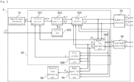
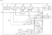
- Fig. 1 is a block diagram of a configuration example of a synchronous-machine drive system 4 including a synchronous-machine control device 1 according to embodiment 1.
- the synchronous-machine drive system 4 of Fig. 1 is configured to control an operation of a synchronous machine (synchronous motor) 10 according to a control instruction.
- the synchronous machine 10 is, for example, a blushless motor (three-phase blushless motor).
- the synchronous machine 10 includes, for example, a rotator and a stator, the stator provided in a vicinity of the rotator.
- the synchronous-machine drive system 4 of Fig. 1 includes the synchronous-machine control device 1, a drive circuit 2, and the detection circuit 3.
- the drive circuit 2 is configured to drive the synchronous machine 10.
- Fig. 2 illustrates a circuit diagram of a configuration example of the drive circuit 2.
- the drive circuit 2 of Fig. 2 is connected between the synchronous machine 10 and the power supply 11.
- the drive circuit 2 of Fig. 2 is configured to supply drive power to the synchronous machine 10 based on power from the power supply 11.
- the power supply 11 is an alternating current power supply.
- the drive circuit 2 is configured to supply drive power to the synchronous machine 10 based on alternating current power from the power supply 11.
- the drive circuit 2 is configured to supply three-phase alternating current power to the synchronous machine 10, as the drive power.
- the drive circuit 2 includes a converter circuit 21 and an inverter circuit 22.
- the converter circuit 21 is configured to convert alternating current power from the power supply 11 into direct current power.
- the converter circuit 21 includes a rectification circuit 21a and a smoothing circuit 21b.
- the rectification circuit 21a is a diode bridge constituted by a plurality of diodes D1 to D4.
- the power supply 11 is connected between input terminals (a connecting point between the diodes D1, D2 and a connecting point between the diodes D3, D4) of the rectification circuit 21a and the smoothing circuit 21b is connected between output terminals (a connecting point between the diodes D1, D3 and a connecting point between the diodes D2, D4) of the rectification circuit 21a.
- the smoothing circuit 21b includes a series circuit of an inductor L1 and a capacitor C1, and is configured to smooth a voltage between the output terminals of the rectification circuit 21a to output it as a voltage across the capacitor C1. Configurations of the rectification circuit 21a and the smoothing circuit 21b of Fig. 2 are known and detailed description thereof is omitted.
- the inverter circuit 22 is configured to supply three-phase alternating current power to the synchronous machine 10 based on the direct current power from the converter circuit 21.
- the inverter circuit 22 includes a plurality of arms U1, U2, V1, V2, W1, and W2. Each of the plurality of arms U1, U2, V1, V2, W1, and W2 is constituted by a semiconductor switching element such as a transistor.
- a series circuit of the arms U1, U2 is connected in parallel to the capacitor C1 of the converter circuit 21 and constitutes a U-phase leg.
- a series circuit of the arms V1, V2 is connected in parallel to the capacitor C1 of the converter circuit 21 and constitutes a V-phase leg.
- a series circuit of the arms W1, W2 is connected in parallel to the capacitor C1 of the converter circuit 21 and constitutes a W-phase leg.
- the inverter circuit 22 is configured to output a U-phase output voltage v u , a V-phase output voltage v v , and a W-phase output voltage v w to the synchronous machine 10. Configuration of the inverter circuit 22 of Fig. 2 is known and detailed description thereof is omitted.
- the detection circuit 3 of Fig. 1 is configured to detect a current flowing through the synchronous machine 10 and output a detected current indicative of this current (i.e., a detected value of a current flowing through the synchronous machine 10).
- the detection circuit 3 is configured to detect output alternating currents of the U-phase and W-phase legs of the drive circuit 2.
- the detection circuit 3 of Fig. 1 includes a first alternating current sensor 31 and a second alternating current sensor 32.
- the first alternating current sensor 31 is configured to detect an output alternating current (current value) of the U-phase leg of the drive circuit 2 and output a first detected current (first detected current value) indicative of the detected output alternating current (current value) i u to the synchronous-machine control device 1.
- the second alternating current sensor 32 is configured to detect an output alternating current (current value) of the W-phase leg of the drive circuit 2 and output a second detected current (second detected current value) indicative of the detected output alternating current (current value) i w to the synchronous-machine control device 1.
- the synchronous-machine control device 1 of Fig. 1 is connectable to the drive circuit 2 and the detection circuit 3.
- the synchronous-machine control device 1 of Fig. 1 may be realized by a computer system including, at least, one or more processors (microprocessors) and one or more memories, for example.
- the synchronous-machine control device 1 of Fig. 1 may be configured by a logic circuit.
- the synchronous-machine control device 1 of Fig. 1 is configured to drive the synchronous machine 10 according to a given control instruction.
- the synchronous-machine control device 1 is configured to perform a sensorless operation for speed and position of the synchronous machine 10.
- the sensorless operation for speed and position is an operation without using a positional sensor such as an encoder, a resolver, and the like.
- the voltage generator 5 is configured to determine (identify) instruction voltages v u *, v v *, v w * respectively corresponding to the U-phase output voltage v u , the V-phase output voltage v v and the W-phase output voltage v w output from the drive circuit 2 to the synchronous machine 10, based on the control instruction and the detected current (the first detected current i u and the second detected current i w ) from the detection circuit 3.
- the voltage generator 5 is configured to update the instruction voltages v u *, v v *, v w * at s predetermined control period. The voltage generator 5 will be described in detail later.
- the duty generator 6 is configured to perform PWM control of the plurality of semiconductor switching elements of the inverter circuit 22 of the drive circuit 2 to allow the drive circuit 2 to operate the synchronous machine 10.
- the duty generator 6 is configured to perform switching control of the plurality of semiconductor switching elements U1, U2, V1, V2, W1, W2 of the inverter circuit 22 to allow the inverter circuit 22 to supply the three-phase alternating current power to the synchronous machine 10 based on the direct current power from the smoothing circuit 21b.
- the synchronous-machine control unit 52 of Fig. 3 defines signal processing corresponding to a synchronous-machine control process.
- the synchronous-machine control process determines the instruction voltages v u *, v v *, v w * and controls the drive circuit 2 to allow the drive circuit 2 to apply voltages v u , v v , v w corresponding to the instruction voltages v u *, v v *, v w * to the synchronous machine 10.
- the synchronous-machine control unit 52 determines the ⁇ axis and ⁇ axis instruction voltages V ⁇ *, V ⁇ * to determine the instruction voltages v u *, v v *, v w *.
- the instruction amplitude determining unit 521 provides the amplitude
- the magnetic flux estimating unit 524 of Fig. 3 receives the ⁇ axis instruction voltage v ⁇ * and the ⁇ axis instruction voltage v ⁇ * from the voltage instruction determining unit 523 and receives the ⁇ axis detected current i ⁇ and the ⁇ axis detected current i ⁇ from the u, w/ ⁇ , ⁇ conversion unit 54.
- the magnetic flux estimating unit 524 calculates the amplitude
- the instruction phase determining unit 525 determines the phase ⁇ S * based on the instruction rotational speed ⁇ ref *. In one example, the instruction phase determining unit 525 may determine the phase ⁇ S * by integrating the instruction rotational speed ⁇ ref * based on the control cycle. The instruction phase determining unit 525 provides the phase ⁇ S * to the instruction magnetic flux determining unit 522.
- the error variable determining unit 526 determines the error variable ⁇ .
- the error variable ⁇ is defined as an inner product of the magnet magnetic flux ⁇ am and the detected current i a (the reactive power component of the synchronous machine 10).
- the error variable determining unit 526 determines the error variable ⁇ from the ⁇ axis estimated magnetic flux ⁇ ⁇ , the ⁇ axis estimated magnetic flux ⁇ ⁇ , the ⁇ axis detected current i ⁇ , and the ⁇ axis detected current i ⁇ .
- the error variable determining unit 526 calculates the inner product of the magnet magnetic flux ⁇ am and the detected current i a , that is, the error variable ⁇ , from the ⁇ axis magnet magnetic flux ⁇ am_ ⁇ , the ⁇ axis magnet magnetic flux ⁇ am_ ⁇ , the ⁇ axis detected current i ⁇ , and the ⁇ axis detected current i ⁇ .
- the error variable determining unit 526 of Fig. 3 receives the ⁇ axis estimated magnetic flux ⁇ ⁇ and the ⁇ axis estimated magnetic flux ⁇ ⁇ from the magnetic flux estimating unit 524, and receives the a axis detected current i ⁇ and the ⁇ axis detected current i ⁇ from the u, w/ ⁇ , ⁇ conversion unit 54.
- the error variable determining unit 526 determines the error variable ⁇ .
- the error variable determining unit 526 provides the error variable ⁇ to the instruction amplitude determining unit 521.
- a demagnetization amount of the magnet magnetic flux ⁇ a m is known to have a positive correlation with the temperature of the permanent magnet 10a.
- the demagnetization amount is defined as a value obtained by subtracting an estimated value of the magnet magnetic flux ⁇ a m at a given point of time from a standard value of the magnet magnetic flux ⁇ a m .
- the temperature of the permanent magnet 10a has a positive correlation with the surrounding temperature of the synchronous machine 10. Therefore, using the magnet magnetic flux ⁇ a m allows for determining whether the surrounding temperature of the synchronous machine 10 exceeds a predetermined temperature. When the surrounding temperature of the synchronous machine 10 is determined to exceed the predetermined temperature based on the magnet magnetic flux ⁇ a m , the synchronous-machine control device 1 performs the stop process of stopping the synchronous machine 10.
- Fig. 10 illustrates a block diagram of a configuration example of a refrigeration-cycle device 100 according to embodiment 1.
- the refrigeration-cycle device 100 of Fig. 10 constitutes an air conditioner enabling a cooling operation and a heating operation, for example.
- hydrofluorocarbons may include difluoromethane, difluoroethane, trifluoroethane, tetrafluoroethane, pentafluoroethane, pentafluoropropane, hexafluoropropane, heptafluoropropane, pentafluorobutane, and heptafluorocyclopentane.
- hydrofluoroolefins (HFO) may include monofluoropropene, trifluoropropene, tetrafluoropropene, pentafluoropropene, and hexafluorobutene.
- saturated hydrocarbons may include ethane, n-propane, cyclopropane, n-butane, cyclobutane, isobutane (2-methylpropane), methylcyclopropane, n-pentane, isopentane (2-methylbutane), neopentane (2,2-dimetliylpropane), and methylcyclobutane.
- the working medium may further contain a disproportionation inhibitor for suppressing a disproportionation reaction of the ethylene-based fluoroolefin.
- the disproportionation inhibitor may include a saturated hydrocarbon or a haloalkane.
- saturated hydrocarbons may include ethane, n-propane, cyclopropane, n-butane, cyclobutane, isobutane (2-methylpropane), methylcyclopropane, n-pentane, isopentane (2-methylbutane), neopentane (2,2-dimethylpropane), and methylcyclobutane.
- n-propane is preferred.
- fluoroalkane having one to three carbon atoms with a boiling point not greater than 0 °C may include: fluoromethanes such as fluoromethane (boiling point of - 78.2 °C), difluoromethane (boiling point of .6 °C), trifluoromethane (boiling point of -84.4 °C), tetrafluoromethane (boiling point of -127.8 °C), fluoroethanes such as fluoroethane (boiling point of -37.1 °C), 1,1-difluoroethane (boiling point of -24.7 °C), 1,1,1-trifluoroethane (boiling point of -47.2 °C), 1,1,1,2-tetrafluoroethane (boiling point of -26.3 °C), 1,1,1,2,2-pentafluoroethane (boiling point of -
- the refrigeration cycle circuit 102 of Fig. 10 includes a compressor 104, a first heat exchanger 105, an expansion valve 106, a second heat exchanger 107, and a four-way valve 108.
- the refrigeration-cycle device 100 of Fig. 10 includes an outdoor unit 101a and an indoor unit 101b.
- the outdoor unit 101a includes the control device 101, the compressor 104, the first heat exchanger 105, the expansion valve 106, and the four-way valve 108.
- the first heat exchanger 105 enables heat exchange between the outdoor air and the working medium.
- the outdoor unit 101a further includes a first air blower 105a for facilitating heat exchange at the first heat exchanger 105.
- the indoor unit 101b includes the second heat exchanger 107.
- the second heat exchanger 107 enables heat exchange between the indoor air and the working medium.
- the indoor unit 101b further includes a second air blower 107a for facilitating heat exchange at the second heat exchanger 107.
- the first direction is a direction in which the working medium circulates in the refrigeration cycle circuit 102 in the order of the compressor 104, the first heat exchanger 105, the expansion valve 106, and the second heat exchanger 107.
- the compressor 104 compresses and discharges the gaseous working medium, and thus the gaseous working medium is sent to the first heat exchanger 105 through the four-way valve 108.
- the first heat exchanger 105 conducts heat exchange between the outdoor air and the gaseous working medium and then the gaseous working medium is condensed to be liquefied.
- the liquid working medium is decompressed by the expansion valve 106 and is sent to the second heat exchanger 107.
- the second heat exchanger 107 conducts heat exchange between the liquid working medium and the indoor air, and then the liquid working medium evaporates to become the gaseous working medium.
- the gaseous working medium returns to the compressor 104 through the four-way valve 108.
- the first heat exchanger 105 functions as a condenser
- the second heat exchanger 107 functions as an evaporator.
- the indoor unit 101b sends air cooled via heat exchange at the second heat exchanger 107 to an interior during cooling.
- the compressor 104 compresses and discharges the gaseous working medium, and thus the gaseous working medium is sent to the second heat exchanger 107 through the four-way valve 108.
- the second heat exchanger 107 conducts heat exchange between the indoor air and the gaseous working medium and then the gaseous working medium is condensed to be liquefied.
- the liquid working medium is decompressed by the expansion valve 106 and is sent to the first heat exchanger 105.
- the first heat exchanger 105 conducts heat exchange between the liquid working medium and the outdoor air, and then the liquid working medium evaporates to become the gaseous working medium.
- the gaseous working medium returns to the compressor 104 through the four-way valve 108.
- the control device 101 of Fig. 10 controls the refrigeration cycle circuit 102.
- the control device 101 controls the compressor 104, the first air blower 105a, then expansion valve 106, the second air blower 107a, and the four-way valve 108.
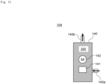
- Fig. 11 is a schematic diagram of a configuration example of the compressor 104 of the refrigeration-cycle device 100.
- the compressor 104 is, for example, a hermetically sealed compressor.
- the compressor 104 may be of a rotary type, a scroll type, or other well-known type.
- the compressor 104 of Fig. 11 includes a sealed container 140, a compression mechanism 141, and a synchronous machine 142.
- the sealed container 140 of Fig. 11 constitutes a fluidic pathway for the working medium 200.
- the sealed container 140 includes a suction pipe 140a and a discharge pipe 140b.
- the working medium 200 is suctioned into the sealed container 140 via the suction pipe 140a and then is compressed by the compression mechanism 141 and thereafter is discharged to an exterior of the sealed container 140 via the discharge pipe 140b.
- the inside of the sealed container 140 is filled with the working medium 200 with a high temperature and a high pressure together with a lubricating oil.
- the sealed container 140 has a bottom part which constitutes an oil reservoir for storing a mixed liquid of the working medium 200 and the lubricating oil.
- the compression mechanism 141 is positioned inside the sealed container 140 to compress the working medium 200.
- the compression mechanism 141 may have a conventional configuration.
- the compression mechanism 141 may include a cylinder forming a compression chamber, a rolling piston disposed in the compression chamber inside the cylinder, and a crank shaft coupled to the rolling piston.
- the synchronous machine 142 is positioned inside the sealed container 140 to operate the compression mechanism 141.
- the synchronous machine 142 is a blushless motor (three-phase blushless motor), for example.
- the synchronous machine 142 includes a plurality of windings (stator windings).
- the plurality of windings include a U-phase winding, a V-phase winding, and a W-phase winding.
- the synchronous machine 142 includes a rotator (permanent magnet) fixed to the crank shaft of the compression mechanism 141 and a stator provided in a vicinity of the rotator, for example.
- the control device 101 includes: the drive circuit 2 configured to drive the synchronous machine 10; the detection circuit 3 configured to detect a current flowing through the synchronous machine 10 to output a detected current indicative of the current; and the synchronous-machine control device 1 connected to the drive circuit 2 and the detection circuit 3.
- the ethylene-based fluoroolefin is 1,1,2-trifluoroethylene, trans-1,2-difluoroethylene, cis-1,2-difluoroethylene, 1,1-difluoroethylene, tetrafluoroethylene, or monofluoroethylene. This configuration enables suppression of a disproportionation reaction of the working medium 200.
- the working medium 200 contains difluoromethane as the refrigerant component. This configuration enables suppression of a disproportionation reaction of the working medium 200.
- the working medium 200 further contains a saturated hydrocarbon. This configuration enables suppression of a disproportionation reaction of the working medium 200.
- the working medium 200 contains a haloalkane with 1 or 2 carbon atoms or fluoroalkane having one, two, or three carbon atoms with a boiling point not greater than 0 °C as a disproportionation inhibitor for suppressing a disproportionation reaction of the ethylene-based fluoroolefin. This configuration enables suppression of a disproportionation reaction of the working medium 200.
- the saturated hydrocarbon contains n-propane. This configuration enables suppression of a disproportionation reaction of the working medium 200.
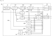
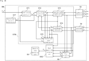
- Fig. 12 is a block diagram of a voltage generator 5A of a synchronous-machine control device according to embodiment 2.
- the voltage generator 5A of Fig. 12 includes the reactive power instruction determining unit 51, a synchronous-machine control unit 52A, the ⁇ , ⁇ /u, v, w conversion unit (two-phase to three-phase coordinate conversion unit) 53, a u, w/ ⁇ , ⁇ conversion unit (three-phase to two-phase coordinate conversion unit) 54, the magnet magnetic flux estimating unit 55, and the operation state determining unit 56.
- Components of the voltage generator 5A of Fig. 12 are visual representations of processing (e.g., signal processing, a transfer function, and the like) performed by the synchronous-machine control device rather than tangible configurations.
- the synchronous-machine control unit 52A of Fig. 12 defines signal processing corresponding to the synchronous-machine control process.
- the synchronous-machine control process determines the instruction voltages v u *, v v * , v w * , and controls the drive circuit 2 to allow the drive circuit 2 to apply the voltages v u , v v , v w corresponding to the instruction voltages v u * , v v * , v w * across the synchronous machine 10.
- the synchronous-machine control unit 52A determines the ⁇ axis and ⁇ axis instruction voltages V ⁇ * , V ⁇ * to thereby determine the instruction voltages v u * , v v *, v w *.
- the synchronous-machine control process determines the instruction voltage v u * , v v * , v w * to allow the reactive power component of the synchronous machine 10 to satisfy the predetermined condition.
- the predetermined condition is that the reactive power component of the synchronous machine 10 is equal to the target value ⁇ * .
- the target value ⁇ * is set to zero.
- the predetermined condition is that the reactive power component becomes zero.
- the synchronous-machine control unit 52A is different from the synchronous-machine control unit 52 in how to determine the phase ⁇ s * of the instruction magnetic flux ⁇ s* .
- the synchronous-machine control process performed by the synchronous-machine control unit 52A determines the estimated phase ⁇ S of the armature flux linkage from the armature flux linkage (the ⁇ axis estimated magnetic flux ⁇ ⁇ , the ⁇ axis estimated magnetic flux ⁇ ⁇ ).
- the synchronous-machine control process determines the estimated torque T e of the synchronous machine 10 from the armature flux linkage (the ⁇ axis estimated magnetic flux ⁇ ⁇ , the ⁇ axis estimated magnetic flux ⁇ ⁇ ) and the detected current (the ⁇ axis detected current i ⁇ , the ⁇ axis detected current i ⁇ ).
- the synchronous-machine control process determines the torque phase to make the estimated torque T e equal to the instruction torque T e * , and adds the torque phase to the estimated phase ⁇ S to determine the phase ⁇ S * of the instruction magnetic flux ⁇ S * . This configuration enables improvement of the accuracy of the phase ⁇ S * of the instruction magnetic flux ⁇ s* .
- the synchronous-machine control unit 52A of Fig. 12 includes the instruction amplitude determining unit 521, the instruction magnetic flux determining unit 522, the voltage instruction determining unit 523, the magnetic flux estimating unit 524, an instruction phase determining unit 525A, the error variable determining unit 526, a phase determining unit 527, and a torque determining unit 528.
- the phase determining unit 527 determines the phase (estimated phase) ⁇ S of the armature flux linkage ⁇ S .
- the phase determining unit 527 estimates the estimated phase ⁇ S from the armature flux linkage (the ⁇ axis estimated magnetic flux ⁇ ⁇ , the ⁇ axis estimated magnetic flux ⁇ ⁇ ).
- the phase determining unit 527 of Fig. 12 receives the ⁇ axis estimated magnetic flux ⁇ ⁇ and the ⁇ axis estimated magnetic flux ⁇ ⁇ from the magnetic flux estimating unit 524.
- the phase determining unit 527 determines the estimated phase ⁇ S .
- the phase determining unit 527 provides the estimated phase ⁇ S to the instruction phase determining unit 525A.
- the torque determining unit 528 determines the torque (estimated torque) T e of the synchronous machine 10.
- the torque determining unit 528 determines the estimated torque T e from the armature flux linkage (the ⁇ axis estimated magnetic flux ⁇ ⁇ , the ⁇ axis estimated magnetic flux ⁇ ⁇ ) and the detected current (the ⁇ axis detected current i ⁇ , the ⁇ axis detected current i ⁇ ).
- the estimated torque T e is represented by the following equation (21).
- P n denotes the number of pole pairs of the synchronous machine 10.
- the torque determining unit 528 of Fig. 12 receives the a axis estimated magnetic flux ⁇ ⁇ and the ⁇ axis estimated magnetic flux ⁇ ⁇ from the magnetic flux estimating unit 524, and receives the ⁇ axis detected current i ⁇ and the ⁇ axis detected current i ⁇ from the u, w/ ⁇ , ⁇ conversion unit 54.
- the torque determining unit 528 determines the estimated torque T e .
- the torque determining unit 528 provides the estimated torque T e to the instruction phase determining unit 525A.
- the instruction phase determining unit 525A determines the phase ⁇ S * of the instruction magnetic flux ⁇ S * of the synchronous machine 10. In the present embodiment, the instruction phase determining unit 525A receives the instruction torque T e * as the control instruction. The instruction phase determining unit 525A receives the estimated phase ⁇ S from the phase determining unit 527, and receives the estimated torque T e from the torque determining unit 528. The instruction phase determining unit 525A determines the phase ⁇ S * based on the instruction torque T e * , the estimated torque T e , and the estimated phase ⁇ S .
- the synchronous-machine control process determines the estimated phase ⁇ S of the armature flux linkage from the armature flux linkage (the ⁇ axis estimated magnetic flux ⁇ ⁇ , the ⁇ axis estimated magnetic flux ⁇ ⁇ ).
- the synchronous-machine control process determines the estimated torque T e of the synchronous machine 10 from the armature flux linkage (the ⁇ axis estimated magnetic flux ⁇ ⁇ , the ⁇ axis estimated magnetic flux ⁇ ⁇ ) and the detected current (the ⁇ axis detected current i ⁇ , the ⁇ axis detected current i ⁇ ).
- the synchronous-machine control process determines the torque phase to allow the estimated torque T e to be equal to the instruction torque T e * , and adds the torque phase to the estimated phase ⁇ S to determine the phase ⁇ S * of the instruction magnetic flux ⁇ S * .
- This configuration enables improvement of the accuracy of the phase ⁇ S * of the instruction magnetic flux ⁇ S * .
- the synchronous-machine control unit 52D determines the ⁇ axis and ⁇ axis instruction voltages V ⁇ *, V ⁇ * to thereby determine the instruction voltages v u * , v v *, v w * .
- the synchronous-machine control process determines the instruction voltage v u * , v v * , v w * to allow the reactive power component of the synchronous machine 10 to satisfy the predetermined condition.
- the predetermined condition is that the reactive power component of the synchronous machine 10 is equal to the target value ⁇ * .
- the target value ⁇ * is set to zero.
- the predetermined condition is that the reactive power component becomes zero.
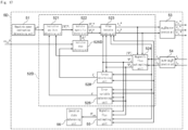
- the synchronous-machine control unit 52D is different from the synchronous-machine control unit 52 in how to determine the phase ⁇ S * of the instruction magnetic flux ⁇ S * .
- the synchronous-machine control process performed by the synchronous-machine control unit 52D determines the variable ⁇ of the phase of the armature flux linkage for each control cycle based on the instruction rotational speed ⁇ r e f * , and determines the phase ⁇ S * of the instruction magnetic flux ⁇ S * based on the variable ⁇ .
- the synchronous-machine control process determines the estimated torque T e of the synchronous machine 10 from the armature flux linkage (the ⁇ axis estimated magnetic flux ⁇ ⁇ , the ⁇ axis estimated magnetic flux ⁇ ⁇ ) and the detected current (the ⁇ axis detected current i ⁇ , the ⁇ axis detected current i ⁇ ).
- the synchronous-machine control process determines the variable ⁇ based on the instruction rotational speed ⁇ r e f * and the estimated torque T e . This configuration enables improvement of stability of the operation of the synchronous machine 10.
- the synchronous-machine control unit 52D of Fig. 17 includes the instruction amplitude determining unit 521, the instruction magnetic flux determining unit 522, the voltage instruction determining unit 523, the magnetic flux estimating unit 524, an instruction phase determining unit 525D, the error variable determining unit526, and the torque determining unit 528.
- the subtractor 503c subtracts, from the instruction rotational speed ⁇ r e f * , the output (K 1 T H ) from the multiplier 503b, and outputs a resultant value.
- K 1 T H represents a speed oscillation component of the synchronous machine 10.
- the integrator 503d determines the variable ⁇ of the phase of the armature flux linkage for each control cycle based on the output ( ⁇ r e f * - K 1 T H ) from the subtractor 503 c.
- the integrator 503d determines the determined variable ⁇ , as the phase ⁇ S * of the instruction magnetic flux ⁇ S * .
- the predetermined condition is that the reactive power component becomes zero. This configuration enables the maximum torque/ampere control of the synchronous machine 10.
- the synchronous-machine control process determines the estimated torque T e of the synchronous machine 10 from the armature flux linkage (the ⁇ axis estimated magnetic flux ⁇ ⁇ , the ⁇ axis estimated magnetic flux ⁇ ⁇ ) and the detected current (the ⁇ axis detected current i ⁇ , the ⁇ axis detected current i ⁇ ).
- the synchronous-machine control process determines the variable ⁇ based on the instruction rotational speed ⁇ r e f * and the estimated torque T e . This configuration enables improvement of stability of the operation of the synchronous machine 10.
- the synchronous-machine control unit 52E of Fig. 19 defines signal processing corresponding to the synchronous-machine control process.
- the synchronous-machine control process determines the instruction voltages v u *, v v " , v w *, and controls the drive circuit 2 to allow the drive circuit 2 to apply the voltages v u , v v , v w corresponding to the instruction voltages v u * , v v * , v w * across the synchronous machine 10.
- the synchronous-machine control unit 52E is different from the synchronous-machine control unit 52 in how to determine the phase ⁇ S * of the instruction magnetic flux ⁇ S *.
- the synchronous-machine control process performed by the synchronous-machine control unit 52E determines a variable of the phase of the armature flux linkage for each control cycle based on the instruction rotational speed ⁇ r e f * , and determines the phase ⁇ S * of the instruction magnetic flux ⁇ S * based on the variable.
- the synchronous-machine control process determines the estimated torque T e of the synchronous machine 10 from the armature flux linkage (the ⁇ axis estimated magnetic flux ⁇ ⁇ , the ⁇ axis estimated magnetic flux ⁇ ⁇ ) and the detected current (the a axis detected current i ⁇ , the ⁇ axis detected current ip).
- the synchronous-machine control process determines the variable ⁇ based on the instruction rotational speed ⁇ r e f * and the estimated torque T e .
- the synchronous-machine control process determines the estimated phase ⁇ S of the armature flux linkage from the armature flux linkage (the ⁇ axis estimated magnetic flux ⁇ ⁇ , the ⁇ axis estimated magnetic flux ⁇ ⁇ ).
- the synchronous-machine control process determines the phase ⁇ S * of the instruction magnetic flux ⁇ S * based on the variable ⁇ and the estimated phase ⁇ S . This configuration enables improvement of the synchronization level between the rotation of the synchronous machine 10 and the rotation of the instruction magnetic flux as well as improvement of stability of the operation of the synchronous machine 10.
- the synchronous-machine control unit 52E of Fig. 19 includes the instruction amplitude determining unit 521, the instruction magnetic flux determining unit522, the voltage instruction determining unit 523, the magnetic flux estimating unit 524, an instruction phase determining unit 525E, the error variable determining unit 526, the phase determining unit 527, and the torque determining unit 528.
- the instruction phase determining unit 525E of Fig. 19 determines the phase ⁇ S * of the instruction magnetic flux ⁇ S * of the synchronous machine 10.
- the instruction phase determining unit 525E receives the estimated phase ⁇ S from the phase determining unit 527:
- the instruction phase determining unit 525E receives the estimated torque T e from the torque determining unit 528.
- the instruction phase determining unit 525E determines the phase ⁇ S * of the instruction magnetic flux ⁇ S * of the synchronous machine 10 by use of the instruction rotational speed ⁇ r e f * , the estimated phase ⁇ S and the estimated torque T e .
- Fig. 20 is a block diagram of a first configuration of the instruction phase determining unit 525E (hereinafter, referred to as the "instruction phase determining unit 525E1", if necessary).
- the instruction phase determining unit 525E1 of Fig. 20 includes a high-pass filter 504a, a multiplier 504b, a subtractor 504c, a multiplier 504d, and an adder 504e.
- the high-pass filter 504a extracts an oscillation component (torque oscillation component) T H of a torque of the synchronous machine 10 from the estimated torque T e and outputs it.
- the multiplier 504b multiplies the oscillation component T H with a gain K 1 and outputs a resultant value.
- the subtractor 504c subtracts, from the instruction rotational speed ⁇ r e f * , the output (K 1 T H ) from the multiplier 504b, and outputs a resultant value.
- the multiplier 504d determines the variable ⁇ of the phase of the armature flux linkage for each control cycle based on the output ( ⁇ r e f * - K 1 T H ) from the subtractor 504c.
- the adder 504e adds the determined variable ⁇ to the estimated phase ⁇ S to calculate the phase ⁇ S * of the instruction magnetic flux ⁇ s * .
- ⁇ S * ⁇ S + ⁇ .
- Fig. 21 is a block diagram of a second configuration of the instruction phase determining unit 525E (hereinafter, referred to as the "instruction phase determining unit 525E2", if necessary).
- the instruction phase determining unit 525E2 of Fig. 21 includes a multiplier 505a, a high-pass filter 505b, a sign inverter 505c, a PI compensator 505d, and adders 505e, 505f.
- the high-pass filter 505b extracts an oscillation component (torque oscillation component) T H of a torque of the synchronous machine 10 from the estimated torque T e and outputs it.
- the sign inverter 505c multiplies the torque oscillation component T H with -1 to output a resultant value.
- the PI compensator 505d determines a correction amount ( ⁇ r e f * T S ) for the variable of the phase of the armature flux linkage for each control cycle in order to allow the output (-T H ) from the sign inverter 505c to become zero.
- the synchronous-machine control process determines the variable of the phase of the armature flux linkage for each control cycle based on the instruction rotational speed ⁇ ref * and determines the phase ⁇ S * of the instruction magnetic flux ⁇ S * based on the variable. Especially, the synchronous-machine control process determines the estimated torque T e of the synchronous machine 10 from the armature flux linkage (the a axis estimated magnetic flux ⁇ ⁇ , the ⁇ axis estimated magnetic flux ⁇ ⁇ ) and the detected current (the ⁇ axis detected current i ⁇ , the ⁇ axis detected current i ⁇ ).
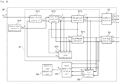
- Fig. 23 is a block diagram of a voltage generator 5F of a synchronous-machine control device according to embodiment 7.
- the voltage generator 5F of Fig. 23 includes the reactive power instruction determining unit 51, the ⁇ , ⁇ /u, v, w conversion unit (two-phase to three-phase coordinate conversion unit) 53, the u, w/ ⁇ , ⁇ conversion unit (three-phase to two-phase coordinate conversion unit) 54, the magnet magnetic flux estimating unit 55, the operation state determining unit 56, a synchronous-machine control unit 57, and a magnetic flux estimating unit 58.
- Components of the voltage generator 5F of Fig. 23 are visual representations of processing (e.g., signal processing, a transfer function, and the like) performed by the synchronous-machine control device rather than tangible configurations.
- the synchronous-machine control unit 57 of Fig. 23 defines signal processing corresponding to the synchronous-machine control process.
- the synchronous-machine control process determines the instruction voltages v u *, v v *, v w *, and controls the drive circuit 2 to allow the drive circuit 2 to apply the voltages v u , v v , v w corresponding to the instruction voltages v u *, v v *, v w * across the synchronous machine 10.
- the synchronous-machine control unit 57 determines dm axis and qm axis instruction voltages V dm *, V qm *, which will be described later, to thereby determine the instruction voltages v u *, v v *, v w *. Therefore, instruction voltages v u *, v v *, v w * are determined by the dm axis and qm axis instruction voltages V dm *, V qm *.
- a UVW coordinate system UVW coordinate axes
- ⁇ coordinate axes an ⁇ coordinate system
- dq coordinate axes a dq coordinate system
- dmqm coordinate system a dmqm coordinate system
- ⁇ coordinate axes a UVW coordinate system
- ⁇ coordinate axes an ⁇ coordinate system
- dq coordinate axes a dmqm coordinate system
- ⁇ coordinate axes a y ⁇ coordinate system
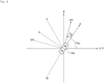
- Fig. 24 is an explanatory diagram of coordinate systems used in the synchronous-machine control device.
- angles mean electric angles.
- the y ⁇ coordinate system of Fig. 24 is a rotating coordinate system based on the rotator (permanent magnet 10a) of the synchronous machine 10.
- the y ⁇ coordinate system may be referred to as an estimated coordinate system.
- the ⁇ coordinate system is a two-dimensional Cartesian coordinate system and is defined by a ⁇ axis and a ⁇ axis perpendicular to each other.
- the ⁇ coordinate system is defined as a coordinate system rotating at a given rotational speed (number of rotations).
- ⁇ dm represents an angle of the dmqm coordinate system relative to the ⁇ coordinate system
- ⁇ m represents an angle of the dq coordinate system relative to the dmqm coordinate system.
- ⁇ ⁇ represents an angle of the dq coordinate system relative to the y ⁇ coordinate system and ⁇ m represents an angle of the dmqm coordinate system relative to the y ⁇ coordinate system.
- ⁇ represents a rotational speed of the synchronous machine 10.
- ⁇ ⁇ represents a rotational speed of the y ⁇ coordinate system.
- v dm * represents a dm axis component of an instruction voltage in the dmqm coordinate system, and hereinafter may be referred to as a dm axis instruction voltage.
- v qm * represents a qm axis component of the instruction voltage in the dmqm coordinate system, and hereinafter may be referred to as a qm axis instruction voltage.
- i dm represents a dm axis component of a detected current in the dmqm coordinate system, and hereinafter may be referred to as a dm axis current.
- i ⁇ represents an ⁇ axis component of a detected current in the ⁇ coordinate system, and hereinafter may be referred to as an ⁇ axis detected current.
- i ⁇ represents a ⁇ axis component of the detected current in the ⁇ coordinate system, and hereinafter may be referred to as a ⁇ axis detected current.
- ⁇ ⁇ represents an ⁇ axis component of an estimated armature flux linkage in the ⁇ coordinate system and hereinafter may be referred to as an ⁇ axis estimated magnetic flux.
- ⁇ ⁇ represents a ⁇ axis component of the estimated armature flux linkage in the ⁇ coordinate system and hereinafter may be referred to as a ⁇ axis estimated magnetic flux.
- ⁇ ref * represents an instruction rotational speed provided as the control instruction.
- the instruction rotational speed ⁇ ref * may be provided from an external device to the synchronous-machine control device 1.
- the synchronous-machine control process determines the instruction voltages v u *, v v *, v w * to allow the reactive power component of the synchronous machine 10 to satisfy the predetermined condition.
- the predetermined condition is that the reactive power component of the synchronous machine 10 becomes equal to the target value.
- the target value is set to zero.
- the predetermined condition is that the reactive power component becomes zero.
- the synchronous-machine control unit 57 of Fig. 23 includes a current instruction generating unit 571, a current control unit 572, a dm, qm/ ⁇ , ⁇ conversion unit 573, an ⁇ , ⁇ /dm, qm conversion unit 574, and a position and speed estimating unit 575.
- the current instruction generating unit 571 generates (determines) the qm axis component (the qm axis instruction current) i qm * of the instruction current.
- the current instruction generating unit 571 determines the qm axis instruction current i qm * from the instruction rotational speed ⁇ ref * and the estimated rotational speed ⁇ e of the synchronous machine 10.
- Examples of the feedback control may include proportional (P) control, proportional-integral (PI) control, proportional-derivative (PD) control and proportional-integral-derivative (PID) control.
- P proportional
- PI proportional-integral
- PD proportional-derivative
- PID proportional-integral-derivative
- K P denotes a proportional gain
- K I denotes an integral gain
- s denotes a Laplace operator.
- the current instruction generating unit 571 of Fig. 23 receives the instruction rotational speed ⁇ ref * from an external device and receives the estimated rotational speed ⁇ e from the position and speed estimating unit 575.
- the current instruction generating unit 571 determines the qm axis instruction current i qm *.
- the current instruction generating unit 571 provides the qm axis instruction current i qm * to the current control unit 572.
- the current control unit 572 determines the dm axis instruction voltage V dm * and the qm axis instruction voltage v qm *. In the present embodiment, the current control unit 572 determines the dm axis instruction voltage v dm * and the qm axis instruction voltage v qm * from the dm axis instruction current i dm *, the qm axis instruction current i qm *, the dm axis current i dm , and the qm axis current i qm .
- the feedback control may include proportional (P) control, proportional-integral (PI) control, proportional-derivative (PD) control and proportional-integral-derivative (PID) control.
- P proportional
- PI proportional-integral
- PD proportional-derivative
- PID proportional-integral-derivative
- the dm axis instruction voltage v dm * and the qm axis instruction voltage V qm * are represented by the following equations (23), (24), respectively.
- K P denotes a proportional gain
- K I denotes an integral gain
- s denotes a Laplace operator.
- K P and K I each may be different between equation (23) and equation (24).
- v dm ⁇ K P + K I s i dm ⁇ ⁇ i dm 1 23
- v qm ⁇ K P + K I s i qm ⁇ ⁇ i qm 1 24
- the current control unit 572 provides the dm axis instruction voltage V dm * and the qm axis instruction voltage v qm * to the dm, qm/ ⁇ , ⁇ conversion unit 573 as well as the position and speed estimating unit 575.
- equation (39) can be represented by the following equation (40).
- ⁇ m tan ⁇ 1 ⁇ v ⁇ + ⁇ L qm i ⁇ v ⁇ ⁇ R a ⁇ ⁇ L dm i ⁇
- the position and speed estimating unit 575 determines the estimated rotational speed ⁇ e by feedback control to allow the angle (i.e., the axis error) ⁇ m of the dmqm coordinate system relative to the ⁇ coordinate system to become zero.
- the estimated rotational speed ⁇ e is represented by the following equation (41).
- K P denotes a proportional gain
- K I denotes an integral gain
- s denotes a Laplace operator.
- the estimated phase ⁇ dm of the synchronous machine 10 can be calculated from time integration of the estimated rotational speed ⁇ e of the synchronous machine 10. Therefore, the estimated phase ⁇ dm is represented by the following equation (42).
- the position and speed estimating unit 575 of Fig. 23 receives the dm axis instruction voltage V dm * and the qm axis instruction voltage v qm * from the current control unit 572, and receives the dm axis current i dm and the qm axis current i qm from the ⁇ , ⁇ /dm, qm conversion unit 574.
- the position and speed estimating unit 575 determines the estimated rotational speed ⁇ e and the estimated phase ⁇ dm .
- the position and speed estimating unit 575 provides the estimated rotational speed ⁇ e to the current instruction generating unit 571.
- the position and speed estimating unit 575 provides the estimated phase ⁇ dm to the dm, qm/ ⁇ , ⁇ conversion unit 573 and the ⁇ , ⁇ /dm, qm conversion unit 574.
- the synchronous-machine control process determines the instruction voltages v u * , v v * , v w * by the dm axis instruction voltage v dm * and the qm axis instruction voltage v qm * in the dmqm coordinate system defined by the dm axis corresponding to a direction of the magnet magnetic flux and the qm axis perpendicular to the dm axis.
- the synchronous-machine control process converts the detected current into the dm axis current i dm and the qm axis current i qm in the dmqm coordinate system.
- the estimated phase ⁇ dm is used for converting the detected current into the dm axis current i dm and the qm axis current i qm in the dmqm coordinate system.
- the synchronous-machine control process determines the qm axis instruction current i qm * in the dmqm coordinate system by performing feedback control using the estimated rotational speed ⁇ e .
- the synchronous-machine control process determines the dm axis instruction voltage V dm * and the qm axis instruction voltage v qm * to allow the reactive power component to satisfy the predetermined condition, based on the qm axis instruction current i qm * . This configuration enables the control of the synchronous machine 10 based on currents.
- the magnetic flux estimating unit 58 of Fig. 23 estimates the armature flux linkage ⁇ S of the synchronous machine 10.
- the magnetic flux estimating unit 58 calculates the ⁇ axis estimated magnetic flux ⁇ ⁇ and the ⁇ axis estimated magnetic flux ⁇ ⁇ .
- the magnetic flux estimating unit 58 calculates the ⁇ axis estimated magnetic flux ⁇ ⁇ and the ⁇ axis estimated magnetic flux ⁇ ⁇ from the ⁇ axis instruction voltage v ⁇ *, the ⁇ axis instruction voltage v ⁇ *, the ⁇ axis detected current i ⁇ , and the ⁇ axis detected current i ⁇ .
- the ⁇ axis estimated magnetic flux ⁇ ⁇ and the ⁇ axis estimated magnetic flux ⁇ ⁇ are represented by the above equations (11) , (12), respectively.
- the magnet magnetic flux estimating unit 55 of Fig. 23 receives the ⁇ axis estimated magnetic flux ⁇ ⁇ and the ⁇ axis estimated magnetic flux ⁇ ⁇ from the magnetic flux estimating unit 58, and receives the ⁇ axis detected current i ⁇ and the ⁇ axis detected current i ⁇ from the u, w/ ⁇ , ⁇ conversion unit 54.
- the magnet magnetic flux estimating unit 55 uses the ⁇ axis estimated magnetic flux ⁇ ⁇ , the ⁇ axis estimated magnetic flux ⁇ ⁇ , the ⁇ axis detected current i ⁇ , and the ⁇ axis detected current i ⁇ to estimate the magnet magnetic flux ⁇ am from the above equation (1).
- the magnet magnetic flux estimating unit 55 provides the magnet magnetic flux ⁇ am to the operation state determining unit 56.
- the synchronous-machine control process determines the instruction voltages v u *, v v *, v w * from the dm axis instruction voltage v dm * and the qm axis instruction voltage v qm * in the dmqm coordinate system defined by the dm axis corresponding to the direction of the magnet magnetic flux and the qm axis perpendicular to the dm axis.
- the synchronous-machine control process converts the detected current into the dm axis current i dm and the qm axis current i qm in the dmqm coordinate system.
- the synchronous-machine control process determines the estimated phase ⁇ dm and the estimated rotational speed ⁇ e , of the permanent magnet 10a, from the dm axis instruction voltage v dm * and the qm axis instruction voltage v qm * as well as the dm axis current i dm and the qm axis current i qm .
- the synchronous-machine control process performs feedback control using the estimated rotational speed ⁇ e to determine the qm axis instruction current i qm * in the dmqm coordinate system.
- the reactive power component ⁇ is also represented by the following equation (49) using the ⁇ axis estimated magnetic flux ⁇ ⁇ , the ⁇ axis estimated magnetic flux ⁇ ⁇ , the ⁇ axis detected current i ⁇ , and the ⁇ axis detected current i ⁇ .
- the magnet magnetic flux estimating unit 55G estimates the magnet magnetic flux ⁇ am from the relationship equation represented by equation (50) derived from the relation shown in equation (44). As apparent from equation (50), equation (50) defines calculation using a magnetic flux and does not contain the instruction voltage and the winding resistance as such. Therefore, it is less susceptible to voltage errors. Accordingly, it is possible to improve the accuracy of estimation of the magnet magnetic flux of the permanent magnet 10a of the synchronous machine 10.
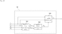
- the magnet magnetic flux estimating unit 55G receives the ⁇ axis estimated magnetic flux ⁇ ⁇ and the ⁇ axis estimated magnetic flux ⁇ ⁇ from the magnetic flux estimating unit 524, receives the ⁇ axis detected current i ⁇ and the ⁇ axis detected current i ⁇ from the u, w/ ⁇ , ⁇ conversion unit 54, and receives the dm axis current i dm from the dm axis current estimating unit 59.
- the predetermined condition is that the reactive power component becomes the predetermined value which is equal to or larger than the predetermined lower limit and is smaller than zero.
- the absolute value of the predetermined lower limit is the product of the rated current of the synchronous machine 10 and the rated magnetic flux of the permanent magnet 10a. This configuration enables the current-weakening control of the synchronous machine 10.
- the synchronous-machine control process calculates the inner product of the magnet magnetic flux and the detected current, performs feedback control using the inner product to determine the amplitude of the instruction magnetic flux of the synchronous machine 10 to allow the reactive power component to satisfy the predetermined condition, determines the phase of the instruction magnetic flux based on the instruction torque of the synchronous machine 10, and determines the instruction voltage based on the amplitude and the phase, of the instruction magnetic flux.
- the synchronous-machine control device includes a function of performing the dm axis current determining process.
- the dm axis current determining process determines the dm axis current i dm in the dmqm coordinate system defined by the dm axis corresponding to the direction of the magnet magnetic flux ⁇ am and the qm axis perpendicular to the dm axis.
- the dm axis current determining process determines the position (angle ⁇ dm ) of the permanent magnet 10a in the dmqm coordinate system from the armature flux linkage ⁇ S (the ⁇ axis estimated magnetic flux ⁇ ⁇ and the ⁇ axis estimated magnetic flux ⁇ ⁇ ) and the detected currenti a (the ⁇ axis detected current i ⁇ and the ⁇ axis detected current i ⁇ ), and determines the dm axis current i dm from the position (angle ⁇ dm ) of the permanent magnet 10a and the detected current i a (the ⁇ axis detected current i ⁇ and the ⁇ axis detected current i ⁇ ).
- the magnet magnetic flux estimating process estimates the magnet magnetic flux ⁇ am from the relationship equation among the magnet magnetic flux ⁇ am , the reactive power component ⁇ , and the dm axis current i d m which is represented by equation (50) and i ⁇ derived from the relation which is represented by equation (44) and is satisfied by the armature flux linkage ⁇ S of the synchronous machine 10, the armature reaction flux L qm i a of the synchronous machine 10, and the magnet magnetic flux ⁇ am of the permanent magnet 10a of the synchronous machine 10.
- This configuration enables control of the synchronous machine (10) based on the magnetic flux.
- Fig. 30 is a block diagram of a voltage generator 5H of a synchronous-machine control device according to embodiment 9.
- the voltage generator 5H of Fig. 30 includes the reactive power instruction determining unit 51, a synchronous-machine control unit 52H, the ⁇ ⁇ /u, v, w conversion unit (two-phase to three-phase coordinate conversion unit) 53, the u, w/ ⁇ , ⁇ conversion unit (three-phase to two-phase coordinate conversion unit) 54, the magnet magnetic flux estimating unit 55G, the operation state determining unit 56 and the dm axis current estimating unit 59.
- Components of the voltage generator 5H of Fig. 30 are visual representations of processing (e.g., signal processing, a transfer function, and the like) performed by the synchronous-machine control device rather than tangible configurations.
- the synchronous-machine control unit 52H of Fig. 30 defines signal processing corresponding to the synchronous-machine control process.
- the synchronous-machine control process determines the instruction voltages v u *, v v *, v w *, and controls the drive circuit 2 to allow the drive circuit 2 to apply the voltages v u , v v , v w corresponding to the instruction voltages v u * , v v *, v w * across the synchronous machine 10.
- the synchronous-machine control unit 52H determines the ⁇ axis and ⁇ axis instruction voltages V ⁇ *, V ⁇ * to thereby determine the instruction voltages v u *, v v *, v w *.
- the synchronous-machine control process determines the instruction voltage v u *, v v *, v w * to allow the reactive power component of the synchronous machine 10 to satisfy the predetermined condition.
- the predetermined condition is that the reactive power component of the synchronous machine 10 is equal to the target value ⁇ *.
- the target value ⁇ * is set to a predetermined value (negative predetermined value) which is equal to or larger than a predetermined lower limit and is smaller than zero.
- the predetermined condition is that the reactive power component becomes the predetermined value (negative predetermined value) which is equal to or larger than the predetermined lower limit and is smaller than zero.
- the synchronous-machine control unit 52H of Fig. 30 includes the instruction amplitude determining unit 521, the instruction magnetic flux determining unit 522, the voltage instruction determining unit 523, the magnetic flux estimating unit 524, the instruction phase determining unit 525A, the error variable determining unit 526, the phase determining unit 527, and the torque determining unit 528.
- the magnetic flux estimating unit 524 provides the ⁇ axis estimated magnetic flux ⁇ ⁇ and the ⁇ axis estimated magnetic flux ⁇ ⁇ to the dm axis current estimating unit 59 in addition to the voltage instruction determining unit 523, the error variable determining unit 526 and the magnet magnetic flux estimating unit 55G.
- the synchronous-machine control unit 52H receives the instruction torque T e * as the control instruction.
- the synchronous-machine control process performed by the synchronous-machine control unit 52H is similar to the synchronous-machine control process performed by the synchronous-machine control unit 52A of Fig. 12 .
- the synchronous-machine control process performed by the synchronous-machine control unit 52H determines the estimated phase ⁇ s of the armature flux linkage from the armature flux linkage (the ⁇ axis estimated magnetic flux ⁇ ⁇ , the ⁇ axis estimated magnetic flux ⁇ ⁇ ).
- the synchronous-machine control process determines the estimated torque T e of the synchronous machine 10 from the armature flux linkage (the ⁇ axis estimated magnetic flux ⁇ ⁇ , the ⁇ axis estimated magnetic flux ⁇ ⁇ ) and the detected current (the ⁇ axis detected current i ⁇ , the ⁇ axis detected current i ⁇ ).
- the synchronous-machine control process determines the torque phase to allow the estimated torque T e to be equal to the instruction torque T e *, and adds the torque phase to the estimated phase ⁇ s to thereby determine the phase ⁇ s* of the instruction magnetic flux ⁇ s*. This configuration enables improvement of the accuracy of the phase ⁇ s* of the instruction magnetic flux ⁇ s*.
- the predetermined condition is that the reactive power component becomes the predetermined value which is equal to or larger than the predetermined lower limit and is smaller than zero.
- the absolute value of the predetermined lower limit is the product of the rated current of the synchronous machine 10 and the rated magnetic flux of the permanent magnet 10a. This configuration enables the current-weakening control of the synchronous machine 10.
- the synchronous-machine control process determines the estimated phase ⁇ S of the armature flux linkage from the armature flux linkage (the ⁇ axis estimated magnetic flux ⁇ ⁇ , the ⁇ axis estimated magnetic flux ⁇ ⁇ ).
- the synchronous-machine control process determines the estimated torque T e of the synchronous machine 10 from the armature flux linkage (the ⁇ axis estimated magnetic flux ⁇ ⁇ , the ⁇ axis estimated magnetic flux ⁇ ⁇ ) and the detected current (the ⁇ axis detected current i ⁇ , the ⁇ axis detected current i ⁇ ).
- the synchronous-machine control process determines the torque phase to allow the estimated torque T e to be identical to the instruction torque T e * , and determines the phase ⁇ S * of the instruction magnetic flux ⁇ S * by adding the torque phase to the estimated phase ⁇ S .
- This configuration enables improvement of the accuracy of the phase ⁇ S * of the instruction magnetic flux ⁇ S *.
- Fig. 31 is a block diagram of a voltage generator 5I of a synchronous-machine control device according to embodiment 10.
- the voltage generator 51 of Fig. 31 includes the reactive power instruction determining unit 51, a synchronous-machine control unit 521, the ⁇ ⁇ /u, v, w conversion unit (two-phase to three-phase coordinate conversion unit) 53, the u, w/ ⁇ , ⁇ conversion unit (three-phase to two-phase coordinate conversion unit) 54, the magnet magnetic flux estimating unit 55G, the operation state determining unit 56 and the dm axis current estimating unit 59.
- Components of the voltage generator 51 of Fig. 31 are visual representations of processing (e.g., signal processing, a transfer function, and the like) performed by the synchronous-machine control device rather than tangible configurations.
- the synchronous-machine control unit 52I of Fig. 31 defines signal processing corresponding to the synchronous-machine control process.
- the synchronous-machine control process determines the instruction voltages v u *, v v *, v w *, and controls the drive circuit 2 to allow the drive circuit 2 to apply the voltages v u , v v , v w corresponding to the instruction voltages v u *, v v *, v w * across the synchronous machine 10.
- the synchronous-machine control unit 521 determines the ⁇ axis and ⁇ axis instruction voltages V ⁇ *, V ⁇ * to thereby determine the instruction voltages v u *, v v *, v w *.
- the synchronous-machine control unit 52K of Fig. 33 includes the instruction amplitude determining unit 521, the instruction magnetic flux determining unit 522, the voltage instruction determining unit 523, the magnetic flux estimating unit 524, the instruction phase determining unit 525D, the error variable determining unit 526, and the torque determining unit 528.
- the magnetic flux estimating unit 524 provides the ⁇ axis estimated magnetic flux ⁇ ⁇ and the ⁇ axis estimated magnetic flux ⁇ ⁇ to the dm axis current estimating unit 59 in addition to the voltage instruction determining unit 523, the error variable determining unit 526 and the magnet magnetic flux estimating unit 55G.
- the synchronous-machine control process performed by the synchronous-machine control unit 52K determines the variable ⁇ of the phase of the armature flux linkage for each control cycle based on the instruction rotational speed ⁇ ref *, and determines the phase ⁇ S * of the instruction magnetic flux ⁇ S * based on the variable ⁇ , Especially, the synchronous-machine control process determines the estimated torque T e of the synchronous machine 10 from the armature flux linkage (the ⁇ axis estimated magnetic flux ⁇ ⁇ , the ⁇ axis estimated magnetic flux ⁇ ) and the detected current (the ⁇ axis detected current i ⁇ , the ⁇ axis detected current i ⁇ ). The synchronous-machine control process determines the variable ⁇ based on the instruction rotational speed ⁇ ref * and the estimated torque T e . This configuration enables improvement of stability of the operation of the synchronous machine 10.
- the predetermined condition is that the reactive power component becomes the predetermined value which is equal to or larger than the predetermined lower limit and is smaller than zero.
- the absolute value of the predetermined lower limit is the product of the rated current of the synchronous machine 10 and the rated magnetic flux of the permanent magnet 10a. This configuration enables the current-weakening control of the synchronous machine 10.
- the synchronous-machine control process determines the estimated torque T e of the synchronous machine 10 from the armature flux linkage (the ⁇ axis estimated magnetic flux ⁇ ⁇ the ⁇ axis estimated magnetic flux ⁇ ⁇ ) and the detected current (the ⁇ axis detected current i ⁇ , the ⁇ axis detected current i ⁇ ).
- the synchronous-machine control process determines the variable ⁇ based on the instruction rotational speed ⁇ ref * and the estimated torque T e . This configuration enables improvement of stability of the operation of the synchronous machine 10.
- Fig. 34 is a block diagram of a voltage generator 5L of a synchronous-machine control device according to embodiment 13.
- the voltage generator 5L of Fig. 34 includes the reactive power instruction determining unit 51, a synchronous-machine control unit 52L, the ⁇ , ⁇ /u, v, w conversion unit (two-phase to three-phase coordinate conversion unit) 53, the u, w/ ⁇ , ⁇ conversion unit (three-phase to two-phase coordinate conversion unit) 54, the magnet magnetic flux estimating unit 55G, the operation state determining unit 56, and the dm axis current estimating unit 59.
- Components of the voltage generator 5L of Fig. 34 are visual representations of processing (e.g., signal processing, a transfer function, and the like) performed by the synchronous-machine control device rather than tangible configurations.
- the synchronous-machine control unit 52L of Fig. 34 defines signal processing corresponding to the synchronous-machine control process.
- the synchronous-machine control process determines the instruction voltages v u *, v v *, v w *, and controls the drive circuit 2 to allow the drive circuit 2 to apply the voltages v u , v v , v w corresponding to the instruction voltages v u *, v v *, v w * across the synchronous machine 10.
- the synchronous-machine control unit 52L determines the ⁇ axis and ⁇ axis instruction voltages V ⁇ *, V ⁇ * to thereby determine the instruction voltages v u *, v v *, v w *.
- the synchronous-machine control process determines the instruction voltage v u *, v v *, v w * to allow the reactive power component of the synchronous machine 10 to satisfy the predetermined condition.
- the predetermined condition is that the reactive power component of the synchronous machine 10 is equal to the target value ⁇ *.
- the target value ⁇ * is set to a predetermined value (negative predetermined value) which is equal to or larger than a predetermined lower limit and is smaller than zero.
- the predetermined condition is that the reactive power component becomes the predetermined value (negative predetermined value) which is equal to or larger than the predetermined lower limit and is smaller than zero.
- the synchronous-machine control unit 52L of Fig. 34 includes the instruction amplitude determining unit 521, the instruction magnetic flux determining unit 522, the voltage instruction determining unit 523, the magnetic flux estimating unit 524, the instruction phase determining unit 525E, the error variable determining unit 526, the phase determining unit 527, and the torque determining unit 528.
- the magnetic flux estimating unit 524 provides the ⁇ axis estimated magnetic flux ⁇ ⁇ and the ⁇ axis estimated magnetic flux ⁇ ⁇ to the dm axis current estimating unit 59 in addition to the voltage instruction determining unit 523, the error variable determining unit 526 and the magnet magnetic flux estimating unit 55G.
- the synchronous-machine control unit 52L receives the instruction rotational speed ⁇ ref * as the control instruction.
- the synchronous-machine control process performed by the synchronous-machine control unit 52L is similar to the synchronous-machine control process performed by the synchronous-machine control unit 52E of Fig. 19 . Therefore, the synchronous-machine control process performed by the synchronous-machine control unit 52L determines a variable of the phase of the armature flux linkage for each control cycle based on the instruction rotational speed ⁇ ref *, and determines the phase ⁇ S * of the instruction magnetic flux ⁇ S * based on the variable.
- the synchronous-machine control process determines the estimated torque T e of the synchronous machine 10 from the armature flux linkage (the ⁇ axis estimated magnetic flux ⁇ ⁇ , the ⁇ axis estimated magnetic flux ⁇ ⁇ ) and the detected current (the ⁇ axis detected current i ⁇ , the ⁇ axis detected current i ⁇ ).
- the synchronous-machine control process determines the variable ⁇ based on the instruction rotational speed ⁇ ref * and the estimated torque T e .
- the synchronous-machine control process determines the estimated phase ⁇ S of the armature flux linkage from the armature flux linkage (the ⁇ axis estimated magnetic flux ⁇ ⁇ , the ⁇ axis estimated magnetic flux ⁇ ⁇ ).
- the synchronous-machine control process determines the phase ⁇ S * of the instruction magnetic flux ⁇ S * based on the variable ⁇ and the estimated phase ⁇ S . This configuration enables improvement of the synchronization level between the rotation of the synchronous machine 10 and the rotation of the instruction magnetic flux as well as improvement of stability of the operation of the synchronous machine 10.
- the predetermined condition is that the reactive power component becomes the predetermined value which is equal to or larger than the predetermined lower limit and is smaller than zero.
- the absolute value of the predetermined lower limit is the product of the rated current of the synchronous machine 10 and the rated magnetic flux of the permanent magnet 10a. This configuration enables the current-weakening control of the synchronous machine 10.
- the synchronous-machine control process determines the variable of the phase of the armature flux linkage for each control cycle based on the instruction rotational speed ⁇ ref * and determines the phase ⁇ S * of the instruction magnetic flux ⁇ S * based on the variable. Especially, the synchronous-machine control process determines the estimated torque T e of the synchronous machine 10 from the armature flux linkage (the ⁇ axis estimated magnetic flux ⁇ ⁇ , the ⁇ axis estimated magnetic flux ⁇ ⁇ ) and the detected current (the ⁇ axis detected current i ⁇ , the ⁇ axis detected current i ⁇ ).
- the synchronous-machine control process determines the variable ⁇ based on the instruction rotational speed ⁇ ref * and the estimated torque T e .
- the synchronous-machine control process determines the estimated phase ⁇ S of the armature flux linkage from the armature flux linkage (the ⁇ axis estimated magnetic flux ⁇ ⁇ , the ⁇ axis estimated magnetic flux ⁇ ⁇ ).
- the synchronous-machine control process determines the phase ⁇ S * of the instruction magnetic flux ⁇ S * based on the variable ⁇ and the estimated phase ⁇ S . This configuration enables improvement of the synchronization level between the rotation of the synchronous machine 10 and the rotation of the instruction magnetic flux as well as the stability of the operation of the synchronous machine 10.
- Fig. 35 is a block diagram of a voltage generator 5M of a synchronous-machine control device according to embodiment 14.
- the voltage generator 5M of Fig. 35 includes the reactive power instruction determining unit 51F, the ⁇ , ⁇ /u, v, w conversion unit (two-phase to three-phase coordinate conversion unit) 53, the u, w/ ⁇ , ⁇ conversion unit (three-phase to two-phase coordinate conversion unit) 54, the magnet magnetic flux estimating unit 55G, the operation state determining unit 56, the synchronous-machine control unit 57M, and the magnetic flux estimating unit 58.
- Components of the voltage generator 5M of Fig. 35 are visual representations of processing (e.g., signal processing, a transfer function, and the like) performed by the synchronous-machine control device rather than tangible configurations.
- the synchronous-machine control unit 52M of Fig. 35 defines signal processing corresponding to the synchronous-machine control process.
- the synchronous-machine control process determines the instruction voltages v u *, v v *, v w *, and controls the drive circuit 2 to allow the drive circuit 2 to apply the voltages v u , v v , v w corresponding to the instruction voltages v u *, v v *, v w * across the synchronous machine 10.
- the synchronous-machine control unit 52L determines the ⁇ axis and ⁇ axis instruction voltages V ⁇ *, V ⁇ * to thereby determine the instruction voltages v u *, v v *, v w *.
- the synchronous-machine control process determines the instruction voltage v u *, v v *, v w * to allow the reactive power component of the synchronous machine 10 to satisfy the predetermined condition.
- the predetermined condition is that the reactive power component of the synchronous machine 10 is equal to the target value ⁇ *.
- the target value ⁇ * is set to a predetermined value (negative predetermined value) which is equal to or larger than a predetermined lower limit and is smaller than zero.
- the predetermined condition is that the reactive power component becomes the predetermined value (negative predetermined value) which is equal to or larger than the predetermined lower limit and is smaller than zero.
- the synchronous-machine control unit 57K of Fig. 35 includes the current instruction generating unit 571, the current control unit 572, the dm, qm/ ⁇ , ⁇ conversion unit 573, the ⁇ , ⁇ /dm, qm conversion unit 574, and the position and speed estimating unit 575.
- the ⁇ , ⁇ /dm, qm conversion unit 574 also provides the dm axis current i dm to the magnet magnetic flux estimating unit 55G.
- the synchronous-machine control unit 52M receives the instruction rotational speed ⁇ ref * as the control instruction.
- the synchronous-machine control process performed by the synchronous-machine control unit 52M is similar to the synchronous-machine control process performed by the synchronous-machine control unit 57 of Fig. 23 .
- the synchronous-machine control process performed by the synchronous-machine control unit 52M determines the instruction voltages v u * , v v *, v w * from the dm axis instruction voltage v dm * and the qm axis instruction voltage v qm * in the dmqm coordinate system defined by the dm axis corresponding to the direction of the magnet magnetic flux and the qm axis perpendicular to the dm axis.
- the synchronous-machine control process converts the detected current into the dm axis current i dm and the qm axis current i qm in the dmqm coordinate system.
- the synchronous-machine control process performs feedback control using the dm axis current i dm and the qm axis current i qm to determine the dm axis instruction voltage v dm * and the qm axis instruction voltage v qm * to allow the reactive power component to satisfy the predetermined condition.
- the synchronous-machine control process determines the estimated phase ⁇ dm and the estimated rotational speed ⁇ e , of the permanent magnet 10a, from the dm axis instruction voltage v dm * and the qm axis instruction voltage v qm * as well as the dm axis current i d m and the qm axis current i qm .
- the estimated phase ⁇ dm is used for converting the detected current into the dm axis current i dm and the qm axis current i qm in the dmqm coordinate system.
- the predetermined condition is that the reactive power component becomes the predetermined value which is equal to or larger than the predetermined lower limit and is smaller than zero.
- the absolute value of the predetermined lower limit is the product of the rated current of the synchronous machine 10 and the rated magnetic flux of the permanent magnet 10a. This configuration enables the current-weakening control of the synchronous machine 10.
- the synchronous-machine control process performs feedback control using the dm axis current and the qm axis current to determine the dm axis instruction voltage v dm * and the qm axis instruction voltage v qm* to allow the reactive power component to satisfy the predetermined condition.
- the magnet magnetic flux estimating process estimates the magnet magnetic flux ⁇ am from the relationship equation among the magnet magnetic flux ⁇ am , the reactive power component ⁇ , and the dm axis current i dm which is represented by equation (50) and is derived from the relation which is represented by equation (44) and is satisfied by the armature flux linkage ⁇ S of the synchronous machine 10, the armature reaction flux L qm i a of the synchronous machine 10, and the magnet magnetic flux ⁇ am of the permanent magnet 10a of the synchronous machine 10.
- This configuration enables control of the synchronous machine 10 based on currents.
- Embodiments of the present disclosure are not limited to the above embodiments.
- the above embodiments may be modified in various ways in accordance with designs or the like to an extent that they can achieve the problem of the present disclosure.
- some variations or modifications of the above embodiments will be listed.
- One or more of the variations or modifications described below may apply in combination with one or more of the others.
- the synchronous-machine control process calculates an inner product of the magnet magnetic flux ⁇ am and the detected current i a , and performs feedback control using the inner product to determine the amplitude
- the synchronous-machine control process may calculate an inner product of the armature flux linkage ⁇ S and the detected current i a , perform feedback control using the inner product to determine the amplitude
- the error variable determining unit 526 determines an inner product ⁇ 1 of the armature flux linkage ⁇ S and the detected current i a .
- the error variable determining unit 526 determines the inner product ⁇ 1 of the armature flux linkage ⁇ S and the detected current i a from the a axis estimated magnetic flux ⁇ ⁇ , the ⁇ axis estimated magnetic flux ⁇ ⁇ , the ⁇ axis detected current i ⁇ , and the ⁇ axis detected current i ⁇ .
- the instruction amplitude determining unit 521 of Fig. 3 receives the target value ⁇ * from the reactive power instruction determining unit 51, receives the amplitude
- the instruction amplitude determining unit 521 uses the amplitude
- , performs feedback control to allow a difference between the inner product ⁇ 1 and a reference value ⁇ 2 to be equal or identical to the target value ⁇ * (a deviation of the difference between the inner product ⁇ 1 and the reference value ⁇ 2 ( ⁇ 2 - ⁇ 1 ) from the target value ⁇ * becomes zero) to determine the correction amount ⁇ , and thereby determines the amplitude
- the feedback control may include proportional (P) control, proportional-integral (PI) control, proportional-derivative (PD) control and proportional-integral-derivative (PID) control.
- P proportional
- PI proportional-integral
- PD proportional-derivative
- PID proportional-integral-derivative
- K P denotes a proportional gain
- K 1 denotes an integral gain
- s denotes a Laplace operator.
- the feedback control using the first inner product may apply to the voltage generators 5A, 5G, 5H of embodiments 2, 8, 9, in addition to the voltage generator 5 of embodiment 1. Further, the feedback control using the first inner product may apply to a case where the control instruction is the instruction rotational speed ⁇ ref *. This means that the voltage generators 5B to 5E and 5I to 5L of embodiments 3 to 6 and 10 to 13 can perform the feedback control using the first inner product.
- the synchronous-machine control process may use any of the inner product (first inner product) of the armature flux linkage ⁇ S and the detected currenti a and the inner product (second inner product) of the magnet magnetic flux ⁇ am and the detected current i a in order to determine the amplitude
- the synchronous machine controlling process may calculate the first inner product of the armature flux linkage ⁇ S and the detected current i a , or, a second inner product of the magnet magnetic flux ⁇ a m and the detected current i a and perform feedback control using the first inner product or the second inner product to determine the amplitude
- the synchronous-machine control process may determine the phase ⁇ S * of the instruction magnetic flux ⁇ s* based on the instruction torque T e * or the instruction rotational speed ⁇ r e f *, of the synchronous machine 10 and determine the instruction voltages v u *, v v *, v w * based on the amplitude
- This configuration enables control of the synchronous machine 10 based on the magnetic flux.
- the instruction phase determining unit 525B may not be limited to the configuration shown in Fig. 14 and it is sufficient that the instruction phase determining unit 525B can determine the phase ⁇ s * of the instruction magnetic flux ⁇ s* of the synchronous machine 10 by use of the instruction rotational speed ⁇ r e f *.
- the instruction phase determining unit 525C may not be limited to the configuration shown in Fig. 16 and it is sufficient that the instruction phase determining unit 525C can determine the phase ⁇ S * of the instruction magnetic flux ⁇ s* of the synchronous machine 10 by use of the instruction rotational speed ⁇ r e f * and the estimated phase ⁇ S .
- the instruction phase determining unit 525D may not be limited to the configuration shown in Fig. 18 and it is sufficient that the instruction phase determining unit 525D can determine the phase ⁇ S * of the instruction magnetic flux ⁇ s* of the synchronous machine 10 by use of the instruction rotational speed ⁇ r e f * and the estimated torque T e .
- the instruction phase determining unit 525E may not be limited to the configuration shown in Fig. 20 , Fig. 21 or Fig.
- the operation state determining unit 56 may be configured to detect a sing of failure of the synchronous machine 10 or determine whether or not the synchronous machine 10 is in failure.
- the synchronous-machine control device 1 may be devoid of the operation state determining unit 56.
- the operation state determining unit 56 may be realized by a computer system, such as, a remote server, communicably connected to the synchronous-machine control device 1. Note that, the computer system may be realized by two or more servers.
- the operation state determining unit 56 may be realized by a cloud (cloud computing) or the like.
- the refrigeration cycle device is not limited to an air conditioner with a configuration where one indoor unit is connected to one outdoor unit (so called, a room air conditioner (RAC)).
- the refrigeration cycle device may be an air conditioner with a configuration where a plurality of indoor units are connected to one or more outdoor units (so-called, a package air conditioner (PAC) or a variable refrigerant flow (VRF)).
- the refrigeration cycle device is not limited to an air conditioner, but may be a freezing or refrigerating device such as a refrigerator or a freezer.
- the synchronous-machine control device may apply to devices, apparatuses, or systems other than compression systems or refrigeration-cycle devices.
- the synchronous-machine control device may apply to devices, apparatuses, or systems for speed and sensorless operation of synchronous machines.
- the synchronous-machine control device may apply to: home appliances such as refrigerators, freezers, washing machines, ventilators, and the like; OA equipment such as scanners, printers, and the like; industrial equipment such as robots and the like; medical and healthcare equipment; moving object such as electric vehicles, drones, and the like; and automotive products such as power doors, power seats, and the like.
- a first aspect is a synchronous-machine control device (1) and is connectable to a drive circuit (2) configured to drive a synchronous machine (10) and a detection circuit (3) configured to detect a current flowing through the synchronous machine (10) to output a detected current indicative of the current.
- the synchronous-machine control device (1) includes functions of performing: a synchronous machine controlling process of determining an instruction voltage to be applied across the synchronous machine (10) and controlling the drive circuit (2) to allow the drive circuit (2) to apply a voltage corresponding to the instruction voltage across the synchronous machine (10); and a magnet magnetic flux estimating process of estimating a magnet magnetic flux of a permanent magnet (10a) of the synchronous machine (10).
- the synchronous machine controlling process determines the instruction voltage to allow a reactive power component of the synchronous machine (10) to satisfy a predetermined condition.
- the magnet magnetic flux estimating process estimates the magnet magnetic flux, based on a relation satisfied by an armature flux linkage of the synchronous machine (10), an armature reaction flux of the synchronous machine (10) and the magnet magnetic flux of the permanent magnet (10a) of the synchronous machine (10) when the reactive power component of the synchronous machine (10) satisfies the predetermined condition, from the armature flux linkage calculated from the detected current and the instruction voltage and the armature reaction flux calculated from an inductance of the synchronous machine (10) and the detected current.
- This aspect enables improvement of accuracy of estimation of the magnet magnetic flux of the permanent magnet (10a) of the synchronous machine (10).
- a second aspect is a synchronous-machine control device (1) according to the first aspect.
- the predetermined condition is that the reactive power component becomes zero This aspect enables the maximum torque/ampere control of the synchronous machine (10).
- ⁇ S denotes the armature flux linkage of the synchronous machine 10
- L q m i a denotes the armature reaction flux of the synchronous machine 10
- ⁇ a m denotes the magnet magnetic flux of the permanent magnet 10a of the synchronous machine 10.
- a third aspect is a synchronous-machine control device (1) according to the first or second aspect.
- the synchronous machine controlling process calculates a first inner product of the armature flux linkage and the detected current, or, a second inner product of the magnet magnetic flux and the detected current; performs feedback control using the first inner product or the second inner product to determine an amplitude of an instruction magnetic flux of the synchronous machine (10) to allow the reactive power component to satisfy the predetermined condition; determines a phase of the instruction magnetic flux based on an instruction torque or an instruction rotational speed, of the synchronous machine (10); and determines the instruction voltage based on the amplitude and the phase, of the instruction magnetic flux.
- This aspect enables control of the synchronous machine (10) based on the magnetic flux.
- a fourth aspect is a synchronous-machine control device (1) according to the third aspect.
- the synchronous machine controlling process determines an estimated phase of the armature flux linkage from the armature flux linkage; determines an estimated torque of the synchronous machine (10) from the armature flux linkage and the detected current; determines a torque phase to allow the estimated torque to be identical to the instruction torque; and determines the phase of the instruction magnetic flux by adding the torque phase to the estimated phase.
- a fifth aspect is a synchronous-machine control device (1) according to the third aspect.
- the synchronous machine controlling process determines a variable of the phase of the armature flux linkage for each control cycle based on the instruction rotational speed; and determines the phase of the instruction magnetic flux based on the variable. This aspect enables control of the synchronous machine (10) based on the magnetic flux.
- a sixth aspect is a synchronous-machine control device (1) according to the third aspect.
- the synchronous machine controlling process determines an estimated phase of the armature flux linkage from the armature flux linkage; determines a variable of the phase of the armature flux linkage for each control cycle based on the instruction rotational speed; and determines the phase of the instruction magnetic flux based on the variable and the estimated phase.
- This aspect enables improvement of a synchronization level between the rotation of the synchronous machine (10) and the rotation of the instruction magnetic flux.
- a seventh aspect is a synchronous-machine control device (1) according to the fifth aspect.
- the synchronous machine controlling process determines an estimated torque of the synchronous machine (10) from the armature flux linkage and the detected current; and determines the variable based on the instruction rotational speed and the estimated torque. This aspect enables improvement of stability of the operation of the synchronous machine 10.
- An eighth aspect is a synchronous-machine control device (1) according to the sixth aspect.
- the synchronous machine controlling process determines an estimated torque of the synchronous machine (10) from the armature flux linkage and the detected current; and determines the variable based on the instruction rotational speed and the estimated torque. This aspect enables improvement of stability of the operation of the synchronous machine 10.
- a ninth aspect is a synchronous-machine control device (1) according to the second aspect.
- the synchronous machine controlling process determines the instruction voltage from a dm axis instruction voltage and a qm axis instruction voltage in a dmqm coordinate system defined by a dm axis corresponding to a direction of the magnet magnetic flux and a qm axis perpendicular to the dm axis; converts the detected current into a dm axis current and a qm axis current in the dmqm coordinate system; and performs feedback control using the dm axis current and the qm axis current to determine the dm axis instruction voltage and the qm axis instruction voltage to allow the reactive power component to satisfy the predetermined condition.
- This aspect enables the control of the synchronous machine (10) based on currents.
- a tenth aspect is a synchronous-machine control device (1) according to the first aspect.
- the predetermined condition is that the reactive power component becomes a predetermined value which is equal to or larger than a predetermined lower limit and is smaller than zero.
- An absolute value of the predetermined lower limit is a product of a rated current of the synchronous machine (10) and a rated magnetic flux of the permanent magnet (10a). This aspect enables the current-weakening control of the synchronous machine (10).
- An eleventh aspect is a synchronous-machine control device (1) according to the tenth aspect.
- the synchronous-machine control device (1) includes a function of performing a dm axis current determining process of determining a dm axis current in a dmqm coordinate system defined by a dm axis corresponding to a direction of the magnet magnetic flux and a qm axis perpendicular to the dm axis.
- the synchronous machine controlling process calculates a first inner product of the armature flux linkage and the detected current, or, a second inner product of the magnet magnetic flux and the detected current; performs feedback control using the first inner product or the second inner product to determine an amplitude of an instruction magnetic flux of the synchronous machine (10) to allow the reactive power component to satisfy the predetermined condition; determines a phase of the instruction magnetic flux based on an instruction torque or an instruction rotational speed, of the synchronous machine (10); and determines the instruction voltage based on the amplitude and the phase, of the instruction magnetic flux.
- the dm axis current determining process determines a position of the permanent magnet in the dmqm coordinate system from the armature flux linkage and the detected current; and determines the dm axis current from the position of the permanent magnet and the detected current.
- the magnet magnetic flux estimating process estimates the magnet magnetic flux from a relationship equation among the magnet magnetic flux, the reactive power component and the dm axis current, derived from the relation. This aspect enables control of the synchronous machine (10) based on the magnetic flux.
- the relation can be represented by the following equation (55), wherein ⁇ S denotes the armature flux linkage of the synchronous machine (10), L q m i a denotes the armature reaction flux of the synchronous machine (10), and ⁇ a m denotes the magnet magnetic flux of the permanent magnet (10a) of the synchronous machine (10).
- the relationship equation among the magnet magnetic flux, the reactive power component and the dm axis current, derived from the relation can be represented by the following equation (56), wherein ⁇ a m denotes the magnet magnetic flux, ⁇ denotes the reactive power component, and i d m denotes the dm axis current.
- the reactive power component ⁇ can be represented by the following equation (57).
- ⁇ am ⁇ S ⁇ L qm i a 55
- ⁇ am ⁇ i dm 56
- ⁇ ⁇ S ⁇ L qm i a i a 57
- a twelfth aspect is a synchronous-machine control device (1) according to the eleventh aspect.
- the synchronous machine controlling process determines an estimated phase of the armature flux linkage from the armature flux linkage; determines an estimated torque of the synchronous machine (10) from the armature flux linkage and the detected current; determines a torque phase to allow the estimated torque to be identical to the instruction torque; and determines the phase of the instruction magnetic flux by adding the torque phase to the estimated phase.
- a thirteenth aspect is a synchronous-machine control device (1) according to the eleventh aspect.
- the synchronous machine controlling process determines a variable of the phase of the armature flux linkage for each control cycle based on the instruction rotational speed; and determines the phase of the instruction magnetic flux based on the variable. This aspect enables control of the synchronous machine (10) based on the magnetic flux.
- a fourteenth aspect is a synchronous-machine control device (1) according to the eleventh aspect.
- the synchronous machine controlling process determines an estimated phase of the armature flux linkage from the armature flux linkage; determines a variable of the phase of the armature flux linkage for each control cycle based on the instruction rotational speed; and determines the phase of the instruction magnetic flux based on the variable and the estimated phase.
- This aspect enables improvement of a synchronization level between the rotation of the synchronous machine (10) and the rotation of the instruction magnetic flux.
- a fifteenth aspect is a synchronous-machine control device (1) according to the thirteenth aspect.
- the synchronous machine controlling process determines an estimated torque of the synchronous machine (10) from the armature flux linkage and the detected current; and determines the variable based on the instruction rotational speed and the estimated torque. This aspect enables improvement of stability of the operation of the synchronous machine 10.
- a sixteenth aspect is a synchronous-machine control device (1) according to the fourteenth aspect.
- the synchronous machine controlling process determines an estimated torque of the synchronous machine (10) from the armature flux linkage and the detected current; and determines the variable based on the instruction rotational speed and the estimated torque. This aspect enables improvement of stability of the operation of the synchronous machine 10.
- the synchronous machine controlling process performs feedback control using the dm axis current and the qm axis current to determine the dm axis instruction voltage and the qm axis instruction voltage to allow the reactive power component to satisfy the predetermined condition.
- the magnet magnetic flux estimating process estimates the magnet magnetic flux from a relationship equation among the magnet magnetic flux, the reactive power component and the dm axis current, derived from the relation. This aspect enables the control of the synchronous machine (10) based on currents.
- the relation can be represented by the following equation (58), wherein ⁇ S denotes the armature flux linkage of the synchronous machine (10), L q m i a denotes the armature reaction flux of the synchronous machine (10), and ⁇ a m denotes the magnet magnetic flux of the permanent magnet (10a) of the synchronous machine (10).
- the relationship equation among the magnet magnetic flux, the reactive power component and the dm axis current, derived from the relation can be represented by the following equation (59), wherein ⁇ a m denotes the magnet magnetic flux, ⁇ denotes the reactive power component, and i d m denotes the dm axis current.
- the reactive power component ⁇ can be represented by the following equation (60).
- the control device (101) includes: a drive circuit (2) configured to drive the synchronous machine (142); a detection circuit (3) configured to detect a current flowing through the synchronous machine (142) to output a detected current indicative of the current; and a synchronous-machine control device (1) connected to the drive circuit (2) and the detection circuit (3).
- the magnet magnetic flux estimating process estimates the magnet magnetic flux, based on a relation satisfied by an armature flux linkage of the synchronous machine (142), an armature reaction flux of the synchronous machine (142) and the magnet magnetic flux of the permanent magnet of the synchronous machine (142) when the reactive power component of the synchronous machine (142) satisfies the predetermined condition, from the armature flux linkage calculated from the detected current and the instruction voltage and the armature reaction flux calculated from an inductance of the synchronous machine (142) and the detected current.
- This aspect enables improvement of accuracy of estimation of the magnet magnetic flux of the permanent magnet of the synchronous machine (142).
- the compressor (104) includes: a sealed container (140) constituting a fluidic pathway for the working medium (200); a compression mechanism (141) positioned inside the sealed container (140) to compress the working medium (200); and a synchronous machine (142) positioned inside the sealed container (140) to operate the compression mechanism (141).
- the control device (101) includes: a drive circuit (2) configured to drive the synchronous machine (10); a detection circuit (3) configured to detect a current flowing through the synchronous machine (10) to output a detected current indicative of the current; and a synchronous-machine control device (1) connected to the drive circuit (2) and the detection circuit (3).
- the synchronous-machine control device (1) includes functions of performing: a synchronous machine controlling process of determining an instruction voltage to be applied across the synchronous machine (142) and controlling the drive circuit (2) to allow the drive circuit (2) to apply a voltage corresponding to the instruction voltage across the synchronous machine (142); a magnet magnetic flux estimating process of estimating a magnet magnetic flux of a permanent magnet of the synchronous machine (142); and a stop process of stopping the synchronous machine (142) when a surrounding temperature of the synchronous machine (142) is determined to exceed a predetermined temperature based on the magnet magnetic flux.
- the synchronous machine controlling process determines the instruction voltage to allow a reactive power component of the synchronous machine (142) to satisfy a predetermined condition, and estimates the magnet magnetic flux, based on a relation satisfied by an armature flux linkage of the synchronous machine (142), an armature reaction flux of the synchronous machine (142) and the magnet magnetic flux of the permanent magnet of the synchronous machine (142) when the reactive power component of the synchronous machine (142) satisfies the predetermined condition, from the armature flux linkage calculated from the detected current and the instruction voltage and the armature reaction flux calculated from an inductance of the synchronous machine (142) and the detected current.
- This aspect enables improvement of accuracy of estimation of the magnet magnetic flux of the permanent magnet of the synchronous machine (142).
- the second to eighteenth aspects can be combined with the nineteenth or twentieth aspect in an appropriate manner.
- the second to eighteenth aspects are optional rather than necessary.
- the present disclosure is applicable to synchronous-machine control devices, compression systems, and refrigeration-cycle devices.
- the present disclosure is applicable to a synchronous-machine control device for a sensorless operation for speed and position of a synchronous machine, a compression system for compression of a working medium containing ethylene-based fluoroolefin as a refrigerant component, and a refrigeration-cycle device with a working medium containing ethylene-based fluoroolefin as a refrigerant component.
Landscapes
- Engineering & Computer Science (AREA)
- Power Engineering (AREA)
- Control Of Ac Motors In General (AREA)
Abstract
Description
- The present disclosure relates to synchronous-machine control devices, compression systems, and refrigeration-cycle devices.
-
Patent document 1 discloses a drive control device for a motor. The drive control device disclosed inpatent document 1 includes: PWM current control means for supplying a sinusoidal current having a predetermined amplitude and a predetermined phase according to a torque instruction value to an alternating current motor; voltage phase control means for supplying an alternating current having phase deviated from the predetermined phase according to the torque instruction value to the alternating current motor; control switching means for switching between PWM current control by the PWM current control means and voltage phase control by the voltage phase control means; magnet temperature estimating means for estimating a temperature of a permanent magnet of the alternating current motor; and correcting means for, in switching from the volage phase control to the PWM current control with a voltage amplitude being changed stepwise, correcting the torque instruction value under the PWM current control by calculating a torque under the voltage phase control and a torque under the PWM current control from the temperature of the permanent magnet estimated by the magnet temperature estimating means and adding a torque difference obtained by subtracting the calculated torque under the PWM current control from the calculated torque under the voltage phase control, to the torque instruction value under the PWM current control. - Patent Document 1:
JP 5396906 B -
Patent document 1 estimates the magnet temperature using the magnetic flux (magnet magnetic flux) of the permanent magnet.Patent document 1 estimates the magnet magnetic flux using a dq axis voltage equation and a torque equation of the motor. In this case, equations used for estimation of the magnet magnetic flux include an instruction voltage (a dq axis voltage instruction value) and a winding resistance (seeequations 14 to 20 in patent document 1). Therefore, this is sensitive to a voltage error caused by dead time of an inverter, a resistance, and the like. This may cause a decrease in estimation accuracy of the magnet magnetic flux. - The present disclosure provides a synchronous-machine control device, a compression system, and a refrigeration-cycle device enabling improvement of accuracy of estimation of a magnet magnetic flux of a permanent magnet of a synchronous machine.
- A synchronous-machine control device according one aspect of the present disclosure includes: a drive circuit configured to drive a synchronous machine; a detection circuit configured to detect a current flowing through the synchronous machine to output a detected current indicative of the current; and a control circuit configured to control the drive circuit. The control circuit has functions of performing: a synchronous machine controlling process of determining an instruction voltage to be applied across the synchronous machine and controlling the drive circuit to allow the drive circuit to apply a voltage corresponding to the instruction voltage across the synchronous machine; and a magnet magnetic flux estimating process of estimating a magnet magnetic flux of a permanent magnet of the synchronous machine. The synchronous machine controlling process determines the instruction voltage to allow a reactive power component of the synchronous machine to satisfy a predetermined condition. The magnet magnetic flux estimating process estimates, based on a relation satisfied by an armature flux linkage of the synchronous machine, an armature reaction flux of the synchronous machine and the magnet magnetic flux of the permanent magnet of the synchronous machine when the reactive power component of the synchronous machine satisfies the predetermined condition, the magnet magnetic flux from the armature flux linkage calculated from the detected current and the instruction voltage and the armature reaction flux calculated from an inductance of the synchronous machine and the detected current.
- A compression system according to one aspect of the present disclosure includes: a compressor; and a control device configured to control the compressor. The compressor includes: a sealed container constituting a fluidic pathway for a working medium containing ethylene-based fluoroolefin as a refrigerant component; a compression mechanism positioned inside the sealed container to compress the working medium; and a synchronous machine positioned inside the sealed container to operate the compression mechanism. The control device includes: a drive circuit configured to drive the synchronous machine; a detection circuit configured to detect a current flowing through the synchronous machine to output a detected current indicative of the current; and a synchronous-machine control device connected to the drive circuit and the detection circuit. The synchronous-machine control device includes functions of performing: a synchronous machine controlling process of determining an instruction voltage to be applied across the synchronous machine and controlling the drive circuit to allow the drive circuit to apply a voltage corresponding to the instruction voltage across the synchronous machine; a magnet magnetic flux estimating process of estimating a magnet magnetic flux of a permanent magnet of the synchronous machine; and a stop process of stopping the synchronous machine when a surrounding temperature of the synchronous machine is determined to exceed a predetermined temperature based on the magnet magnetic flux. The synchronous machine controlling process determines the instruction voltage to allow a reactive power component of the synchronous machine to satisfy a predetermined condition. The magnet magnetic flux estimating process estimates, based on a relation satisfied by an armature flux linkage of the synchronous machine, an armature reaction flux of the synchronous machine and the magnet magnetic flux of the permanent magnet of the synchronous machine when the reactive power component of the synchronous machine satisfies the predetermined condition, the magnet magnetic flux from the armature flux linkage calculated from the detected current and the instruction voltage and the armature reaction flux calculated from an inductance of the synchronous machine and the detected current.
- A refrigeration-cycle device according to one aspect of the present disclosure includes: a refrigeration cycle circuit including a compressor, a condenser, an expansion valve and an evaporator, and allowing circulation of a working medium; and a control apparatus configured to control the refrigeration cycle circuit. The working medium contains ethylene-based fluoroolefin as a refrigerant component. The compressor includes: a sealed container constituting a fluidic pathway for the working medium; a compression mechanism positioned inside the sealed container to compress the working medium; and a synchronous machine positioned inside the sealed container to operate the compression mechanism. The control apparatus includes: a drive circuit configured to drive the synchronous machine; a detection circuit configured to detect a current flowing through the synchronous machine to output a detected current indicative of the current; and a synchronous-machine control device connected to the drive circuit and the detection circuit. The synchronous-machine control device includes functions of performing: a synchronous machine controlling process of determining an instruction voltage to be applied across the synchronous machine and controlling the drive circuit to allow the drive circuit to apply a voltage corresponding to the instruction voltage across the synchronous machine; a magnet magnetic flux estimating process of estimating a magnet magnetic flux of a permanent magnet of the synchronous machine; and a stop process of stopping the synchronous machine when a surrounding temperature of the synchronous machine is determined to exceed a predetermined temperature based on the magnet magnetic flux. The synchronous machine controlling process determines the instruction voltage to allow a reactive power component of the synchronous machine to satisfy a predetermined condition. The magnet magnetic flux estimating process estimates, based on a relation satisfied by an armature flux linkage of the synchronous machine, an armature reaction flux of the synchronous machine and the magnet magnetic flux of the permanent magnet of the synchronous machine when the reactive power component of the synchronous machine satisfies the predetermined condition, the magnet magnetic flux from the armature flux linkage calculated from the detected current and the instruction voltage and the armature reaction flux calculated from an inductance of the synchronous machine and the detected current.
- An aspect of the present disclosure enables improvement of accuracy of estimation of a magnet magnetic flux of a permanent magnet of a synchronous machine.
-
-
Fig. 1 is a block diagram of a configuration example of a synchronous-machine drive system including a synchronous-machine control device according toembodiment 1. -
Fig. 2 is a circuit diagram of a configuration example of a drive circuit of the synchronous-machine drive system ofFig. 1 . -
Fig. 3 is a block diagram of a voltage generator of a synchronous-machine control device of the synchronous-machine drive system ofFig. 1 . -
Fig. 4 is an explanatory diagram of coordinate systems used in the synchronous-machine control device ofFig. 3 . -
Fig. 5 is an explanatory diagram of current and flux vectors of the synchronous machine by the synchronous-machine control device ofFig. 3 . -
Fig. 6 is an explanatory diagram of current and flux vectors of the synchronous machine by the synchronous-machine control device ofFig. 3 . -
Fig. 7 is an explanatory diagram of current and flux vectors of the synchronous machine by the synchronous-machine control device ofFig. 3 . -
Fig. 8 is a graph representing one example of comparison between an estimated value and a true value, of a magnet magnetic flux by the synchronous-machine control device ofFig. 1 . -
Fig. 9 is a graph representing another example of comparison between the estimated value and the true value, of the magnet magnetic flux by the synchronous-machine control device ofFig. 1 . -
Fig. 10 is a block diagram of a configuration example of a refrigeration-cycle device according toembodiment 1. -
Fig. 11 is a schematic view of a configuration example of a compressor of the refrigeration-cycle device ofFig. 1 . -
Fig. 12 is a block diagram of a voltage generator of a synchronous-machine control device according toembodiment 2. -
Fig. 13 is a block diagram of a voltage generator of a synchronous-machine control device according toembodiment 3. -
Fig. 14 is a block diagram of a configuration example of an instruction phase determining unit of the voltage generator ofFig. 13 . -
Fig. 15 is a block diagram of a voltage generator of a synchronous-machine control device according toembodiment 4. -
Fig. 16 is a block diagram of a configuration example of an instruction phase determining unit of the voltage generator ofFig. 15 . -
Fig. 17 is a block diagram of a voltage generator of a synchronous-machine control device according toembodiment 5. -
Fig. 18 is a block diagram of a configuration example of an instruction phase determining unit of the voltage generator ofFig. 17 . -
Fig. 19 is a block diagram of a voltage generator of a synchronous-machine control device according to embodiment 6. -
Fig. 20 is a block diagram of a first configuration example of an instruction phase determining unit of the voltage generator ofFig. 19 . -
Fig. 21 is a block diagram of a second configuration example of the instruction phase determining unit of the voltage generator ofFig. 19 . -
Fig. 22 is a block diagram of a third configuration example of the instruction phase determining unit of the voltage generator ofFig. 19 . -
Fig. 23 is a block diagram of a voltage generator of a synchronous-machine control device according to embodiment 7. -
Fig. 24 is an explanatory diagram of coordinate systems used in the synchronous-machine control device ofFig. 23 . -
Fig. 25 is a block diagram of a voltage generator of a synchronous-machine control device according to embodiment 8. -
Fig. 26 is an explanatory diagram of current and flux vectors of a synchronous machine by the synchronous-machine control device ofFig. 25 . -
Fig. 27 is a block diagram of a configuration example of a dm axis current determining unit of the voltage generator ofFig. 25 . -
Fig. 28 is a graph representing one example of comparison between the estimated value and the true value, of the magnet magnetic flux by the synchronous-machine control device ofFig. 25 . -
Fig. 29 is a graph representing another example of comparison between the estimated value and the true value, of the magnet magnetic flux by the synchronous-machine control device ofFig. 25 . -
Fig. 30 is a block diagram of a voltage generator of a synchronous-machine control device according to embodiment 9. -
Fig. 31 is a block diagram of a voltage generator of a synchronous-machine control device according toembodiment 10. -
Fig. 32 is a block diagram of a voltage generator of a synchronous-machine control device according toembodiment 11. -
Fig. 33 is a block diagram of a voltage generator of a synchronous-machine control device according to embodiment 12. -
Fig. 34 is a block diagram of a voltage generator of a synchronous-machine control device according to embodiment 13. -
Fig. 35 is a block diagram of a voltage generator of a synchronous-machine control device according toembodiment 14. - Hereinafter, embodiments of the present disclosure will be described with reference to the drawings where appropriate. However, the following embodiments are merely examples for explaining the present disclosure, and are not intended to limit the present disclosure to the following content. Positional relationships such as up, down, left, and right are based on the positional relationships shown in the drawings, unless otherwise specified. Each figure described in the following embodiments is a schematic diagram, and the ratios of size and thickness of each component in each figure do not necessarily reflect the actual dimensional ratios. Furthermore, the dimensional ratios of each element are not limited to the ratios shown in the drawings.
- Note that, in the following description, same or similar components may be designated by the same reference signs to avoid unnecessary repetition.
- In the following description, if it is necessary to distinguish a plurality of components from each other, prefixes, such as, "first", "second", or the like are attached to names of such components. However, if these components can be distinguished from each other by reference signs attached to those components, such prefixes, such as, "first", "second", or the like, may be omitted in consideration of readability of texts.
- In the following description, symbols representative of physical amounts such as a magnetic flux, a voltage, a current, and the like may indicate vectors when written in bold font, and may indicate scholars when not written in bold font (when written in standard font).
-
Fig. 1 is a block diagram of a configuration example of a synchronous-machine drive system 4 including a synchronous-machine control device 1 according toembodiment 1. The synchronous-machine drive system 4 ofFig. 1 is configured to control an operation of a synchronous machine (synchronous motor) 10 according to a control instruction. - The
synchronous machine 10 is, for example, a blushless motor (three-phase blushless motor). Thesynchronous machine 10 includes, for example, a rotator and a stator, the stator provided in a vicinity of the rotator. - The synchronous-
machine drive system 4 ofFig. 1 includes the synchronous-machine control device 1, adrive circuit 2, and thedetection circuit 3. - The
drive circuit 2 is configured to drive thesynchronous machine 10.Fig. 2 illustrates a circuit diagram of a configuration example of thedrive circuit 2. Thedrive circuit 2 ofFig. 2 is connected between thesynchronous machine 10 and thepower supply 11. Thedrive circuit 2 ofFig. 2 is configured to supply drive power to thesynchronous machine 10 based on power from thepower supply 11. In the present embodiment, thepower supply 11 is an alternating current power supply. Thedrive circuit 2 is configured to supply drive power to thesynchronous machine 10 based on alternating current power from thepower supply 11. Especially, thedrive circuit 2 is configured to supply three-phase alternating current power to thesynchronous machine 10, as the drive power. Thedrive circuit 2 includes aconverter circuit 21 and aninverter circuit 22. - The
converter circuit 21 is configured to convert alternating current power from thepower supply 11 into direct current power. Theconverter circuit 21 includes arectification circuit 21a and a smoothingcircuit 21b. Therectification circuit 21a is a diode bridge constituted by a plurality of diodes D1 to D4. Thepower supply 11 is connected between input terminals (a connecting point between the diodes D1, D2 and a connecting point between the diodes D3, D4) of therectification circuit 21a and the smoothingcircuit 21b is connected between output terminals (a connecting point between the diodes D1, D3 and a connecting point between the diodes D2, D4) of therectification circuit 21a. The smoothingcircuit 21b includes a series circuit of an inductor L1 and a capacitor C1, and is configured to smooth a voltage between the output terminals of therectification circuit 21a to output it as a voltage across the capacitor C1. Configurations of therectification circuit 21a and the smoothingcircuit 21b ofFig. 2 are known and detailed description thereof is omitted. - The
inverter circuit 22 is configured to supply three-phase alternating current power to thesynchronous machine 10 based on the direct current power from theconverter circuit 21. Theinverter circuit 22 includes a plurality of arms U1, U2, V1, V2, W1, and W2. Each of the plurality of arms U1, U2, V1, V2, W1, and W2 is constituted by a semiconductor switching element such as a transistor. A series circuit of the arms U1, U2 is connected in parallel to the capacitor C1 of theconverter circuit 21 and constitutes a U-phase leg. A series circuit of the arms V1, V2 is connected in parallel to the capacitor C1 of theconverter circuit 21 and constitutes a V-phase leg. A series circuit of the arms W1, W2 is connected in parallel to the capacitor C1 of theconverter circuit 21 and constitutes a W-phase leg. Theinverter circuit 22 is configured to output a U-phase output voltage vu, a V-phase output voltage vv, and a W-phase output voltage vw to thesynchronous machine 10. Configuration of theinverter circuit 22 ofFig. 2 is known and detailed description thereof is omitted. - The
detection circuit 3 ofFig. 1 is configured to detect a current flowing through thesynchronous machine 10 and output a detected current indicative of this current (i.e., a detected value of a current flowing through the synchronous machine 10). In the present embodiment, thedetection circuit 3 is configured to detect output alternating currents of the U-phase and W-phase legs of thedrive circuit 2. Thedetection circuit 3 ofFig. 1 includes a first alternatingcurrent sensor 31 and a second alternatingcurrent sensor 32. The first alternatingcurrent sensor 31 is configured to detect an output alternating current (current value) of the U-phase leg of thedrive circuit 2 and output a first detected current (first detected current value) indicative of the detected output alternating current (current value) iu to the synchronous-machine control device 1. The second alternatingcurrent sensor 32 is configured to detect an output alternating current (current value) of the W-phase leg of thedrive circuit 2 and output a second detected current (second detected current value) indicative of the detected output alternating current (current value) iw to the synchronous-machine control device 1. - The synchronous-
machine control device 1 ofFig. 1 is connectable to thedrive circuit 2 and thedetection circuit 3. The synchronous-machine control device 1 ofFig. 1 may be realized by a computer system including, at least, one or more processors (microprocessors) and one or more memories, for example. Alternatively, the synchronous-machine control device 1 ofFig. 1 may be configured by a logic circuit. - The synchronous-
machine control device 1 ofFig. 1 is configured to drive thesynchronous machine 10 according to a given control instruction. The synchronous-machine control device 1 is configured to perform a sensorless operation for speed and position of thesynchronous machine 10. The sensorless operation for speed and position is an operation without using a positional sensor such as an encoder, a resolver, and the like. - The synchronous-
machine control device 1 ofFig. 1 includes avoltage generator 5 and a duty generator 6. Thevoltage generator 5 and the duty generator 6 ofFig. 1 are visual representations of processing (e.g., signal processing, a transfer function, and the like) performed by the synchronous-machine control device 1 rather than tangible configurations. - The
voltage generator 5 is configured to determine (identify) instruction voltages vu*, vv*, vw* respectively corresponding to the U-phase output voltage vu, the V-phase output voltage vv and the W-phase output voltage vw output from thedrive circuit 2 to thesynchronous machine 10, based on the control instruction and the detected current (the first detected current iu and the second detected current iw) from thedetection circuit 3. Thevoltage generator 5 is configured to update the instruction voltages vu*, vv*, vw* at s predetermined control period. Thevoltage generator 5 will be described in detail later. - The duty generator 6 is configured to perform PWM control of the plurality of semiconductor switching elements of the
inverter circuit 22 of thedrive circuit 2 to allow thedrive circuit 2 to operate thesynchronous machine 10. In more detail, the duty generator 6 is configured to perform switching control of the plurality of semiconductor switching elements U1, U2, V1, V2, W1, W2 of theinverter circuit 22 to allow theinverter circuit 22 to supply the three-phase alternating current power to thesynchronous machine 10 based on the direct current power from the smoothingcircuit 21b. In the present embodiment, the duty generator 6 determines duty cycles Du, Dv, Dw of the U-phase, V-phase and W-phase legs of thedrive circuit 2 to allow thedrive circuit 2 to output the U-phase output voltage vu, the V-phase output voltage vv and the W-phase output voltage vw respectively equal to the instruction voltages vu*, vv*, vw* to thesynchronous machine 10. -
Fig. 3 illustrates a block diagram of a configuration example of thevoltage generator 5 of the synchronous-machine control device 1. Thevoltage generator 5 ofFig. 3 includes a reactive powerinstruction determining unit 51, a synchronous-machine control unit 52, an α, β/u, v, w conversion unit (two-phase to three-phase coordinate conversion unit) 53, a u, w/α, β conversion unit (three-phase to two-phase coordinate conversion unit) 54, a magnet magneticflux estimating unit 55, and an operationstate determining unit 56. Components of thevoltage generator 5 shown inFig. 3 (the reactive powerinstruction determining unit 51, the synchronous-machine control unit 52, the α, β/u, v,w conversion unit 53, the u, w/α, βconversion unit 54, the magnet magneticflux estimating unit 55, and the operation state determining unit 56) are visual representations of processing (e.g., signal processing and the like) performed by the synchronous-machine control device 1 rather than tangible configurations. This applies to embodiments described later. - In the present embodiment, an operation of the synchronous-
machine control device 1 will be described by use of a UVW coordinate system (UVW coordinate axes) , an αβ coordinate system (αβ coordinate axes), a dq coordinate system (dq coordinate axes), and a dmqm coordinate system (dmqm coordinate axes).Fig. 4 illustrates an explanatory diagram of coordinate systems used in the synchronous-machine control device 1. With respect to the UVW coordinate system, the αβ coordinate system, the dq coordinate system, and the dmqm coordinate system, angles mean electric angles. - The UVW coordinate system of
Fig. 4 is a fixed coordinate system based on the stator of thesynchronous machine 10 and is defined by a U axis, a V axis and a W axis spaced at 120 degrees intervals. The U axis, the V axis and the W axis are respectively corresponding to U-phase, V-phase and W-phase windings of the stator of thesynchronous machine 10. The U axis, the V axis and the W axis do not rotate with rotation of the rotator of thesynchronous machine 10. This means that the U axis, the V axis and the W axis are fixed axes. - The αβ coordinate system of
Fig. 4 is a two-dimensional Cartesian coordinate system and is defined by an a axis and a β axis perpendicular to each other. The α axis is set to be aligned with the U axis. The β axis is an axis obtained by rotating the α axis by 90 degrees in a direction of advance. Similarly to the UVW coordinate system, the αβ coordinate system is a fixed coordinate system based on the stator of thesynchronous machine 10. - The dq coordinate system of
Fig. 4 is a rotating coordinate system based on the rotator (permanent magnet 10a) of thesynchronous machine 10. The dq coordinate system is a two-dimensional Cartesian coordinate system and is defined by a d axis and a q axis perpendicular to each other. The d axis and the q axis rotate at the same rotational speed (the number of rotations) as the magnetic flux formed by thepermanent magnet 10a relative to the α axis and the β axis. The rotational speed of the magnetic flux formed by thepermanent magnet 10a is equal to a rotational speed of the rotator of thesynchronous machine 10. InFig. 4 , a counterclockwise direction is a direction of phase advance. The d axis is set as an axis extending in a direction of the magnetic flux formed by thepermanent magnet 10a. The q axis is set to be an axis obtained by rotating the d axis by 90 degrees in a direction of advance. - The dmqm coordinate system of
Fig. 4 is a coordinate system set to realize a maximum torque/ampere (maximum torque per ampere: MTPA) control. The dmqm coordinate system is a two-dimensional Cartesian coordinate system and is defined by a dm axis and a qm axis perpendicular to each other. The qm axis is set to allow a direction of the qm axis to be aligned with a direction of a current vector which should be supplied to thesynchronous machine 10 to achieve the maximum torque/ampere control. This means that the qm axis is aligned with the current vector under the maximum torque/ampere control. The dm axis is an axis delayed from the qm axis by 90 degrees. In the dmqm coordinate system, the maximum torque/ampere control can be achieved by setting a dm axis current to zero, the dm axis current being a dm axis component of a current of thesynchronous machine 10. Note that, inFig. 4 , θdm indicates an angle of the dmqm coordinate system relative to the αβ coordinate system and θm indicates an angle of the dq coordinate system relative to the dmqm coordinate system. - Next, with reference to
Fig. 3 , thevoltage generator 5 of the synchronous-machine control device 1 will be described in detail. First, explanation is made to parameters shown in the block diagram ofFig. 3 . ε* is a target value of a reactive power component of thesynchronous machine 10. |ΨS*| is an amplitude of an instruction magnetic flux ΨS* of thesynchronous machine 10. Ψα* is an α axis component of the instruction magnetic flux ΨS* of the αβ coordinate system, and hereinafter may be referred to as an α, axis instruction magnetic flux. Ψβ* is a β axis component of the instruction magnetic flux ΨS* of the αβ coordinate system, and hereinafter may be referred to as a β axis instruction magnetic flux. θS* is a phase of the instruction magnetic flux ΨS* of thesynchronous machine 10. vα* is an α axis component of the instruction voltage in the αβ coordinate system, and hereinafter may be referred to as an α axis instruction voltage. vβ* is a β axis component of the instruction voltage in the αβ coordinate system, and hereinafter may be referred to as a β axis instruction voltage. iα is an α axis of the detected current in the αβ coordinate system, and hereinafter may be referred to as an a axis detected current. iβ is a β axis of the detected current in the αβ coordinate system, and hereinafter may be referred to as a β axis detected current. |ΨS| is an amplitude of an estimated armature flux linkage ΨS of thesynchronous machine 10. Ψα is an α axis component of an estimated armature flux linkage in the αβ coordinate system, and hereinafter referred to as an α axis estimated magnetic flux. Ψβ is a β axis component of the estimated armature flux linkage in the αβ coordinate system, and hereinafter referred to as a β axis estimated magnetic flux. ε is a reactive power component of thesynchronous machine 10, and hereinafter referred to as an error variable. InFig. 3 , Te* is an instruction torque as the control instruction. the instruction torque Te* indicates a target value of a torque of thesynchronous machine 10. The instruction torque Te* may be provided from an external device to the synchronous-machine control device 1. - The reactive power
instruction determining unit 51 ofFig. 3 is configured to determine the target value ε* of the reactive power component of thesynchronous machine 10. The target value ε* is provided to the synchronous-machine control unit 52. The reactive power component of thesynchronous machine 10 is given by an inner product of a magnet magnetic flux of thepermanent magnet 10a of thesynchronous machine 10 and a current flowing through thesynchronous machine 10. To achieve the maximum torque/ampere control, a dm axis current idm is set to 0 in the dmqm coordinate system. In this case, the inner product of the magnet magnetic flux of thepermanent magnet 10a of thesynchronous machine 10 and the current flowing through thesynchronous machine 10 is zero, that is, the target value ε* of the reactive power component of thesynchronous machine 10 is set to zero. -
Fig. 5 is an explanatory diagram of current and flux vectors of thesynchronous machine 10. Especially,Fig. 5 represents a relation among the armature flux linkage of thesynchronous machine 10, an armature reaction flux of thesynchronous machine 10, and a magnet magnetic flux of thepermanent magnet 10a of thesynchronous machine 10 when the reactive power component of thesynchronous machine 10 is zero (the dm axis current idm is zero). ΨS is the armature flux linkage (vector) of thesynchronous machine 10. Ψam is the magnet magnetic flux (vector) of thepermanent magnet 10a. Especially, Ψam is the magnet magnetic flux (vector) of thepermanent magnet 10a in the dmqm coordinate system. In the dmqm coordinate system, Ψam = (Ψam, 0). Lqm is an virtual inductance and means an inductance in the qm axis in the dmqm coordinate system. ia is a current (i.e., the detected current) (vector) flowing through thesynchronous machine 10. In the dmqm coordinate system ia = (idm, iqm). The armature reaction flux of thesynchronous machine 10 is represented by Lqmia. When the dm axis current idm is zero, ia = (0, iqm). The armature reaction flux of thesynchronous machine 10 satisfies that Lqmia = (0, Lqmiqm). - In the case of
Fig. 5 , the armature reaction flux of thesynchronous machine 10 and the magnet magnetic flux of thepermanent magnet 10a of thesynchronous machine 10 are perpendicular to each other. Therefore, when the reactive power component of thesynchronous machine 10 is zero (when the dm axis current idm is zero), a relation satisfied by the armature flux linkage ΨS of thesynchronous machine 10, the armature reaction flux Lqmia of thesynchronous machine 10, and the magnet magnetic flux Ψam of thepermanent magnet 10a of thesynchronous machine 10 can be represented by the following equation (1).
[FORMULA 1]
- The synchronous-
machine control unit 52 ofFig. 3 defines signal processing corresponding to a synchronous-machine control process. The synchronous-machine control process determines the instruction voltages vu*, vv*, vw* and controls thedrive circuit 2 to allow thedrive circuit 2 to apply voltages vu, vv, vw corresponding to the instruction voltages vu*, vv*, vw* to thesynchronous machine 10. In the present embodiment, the synchronous-machine control unit 52 determines the α axis and β axis instruction voltages Vα*, Vβ* to determine the instruction voltages vu*, vv*, vw*. - The synchronous-machine control process determines the instruction voltages vu*, vv*, vw* to allow the reactive power component of the
synchronous machine 10 to satisfy a predetermined condition. In the present embodiment, the predetermined condition is that the reactive power component of thesynchronous machine 10 becomes equal to the target value ε*. In the present embodiment, the target value ε* is set to zero. Accordingly, in the present embodiment, the predetermined condition is that the reactive power component becomes zero. - The synchronous-
machine control unit 52 ofFig. 3 includes an instructionamplitude determining unit 521, an instruction magneticflux determining unit 522, a voltageinstruction determining unit 523, a magneticflux estimating unit 524, an instructionphase determining unit 525, and an errorvariable determining unit 526. - The instruction
amplitude determining unit 521 is configured to determine an amplitude |ΨS*| of an instruction magnetic flux of thesynchronous machine 10 for each control cycle. The amplitude |ΨS*| is determined to allow the reactive power component of thesynchronous machine 10 to satisfy the predetermined condition. In the present embodiment, the predetermined condition is that the reactive power component becomes zero, and this means that the above equation (1) is satisfied. - The reactive power component ε of the
synchronous machine 10 is represented by the following equation (2).
[FORMULA 2]
- The magnet magnetic flux Ψam may contain an error (magnetic flux error) Ψe originating from a voltage error and a resistance error in the
drive circuit 2. In the dmqm coordinate system, considering the magnetic flux error Ψe, the magnet magnetic flux Ψam can be represented by the following equation (3). In equation (3), Ψam0 represents an initial value (vector) of the magnet magnetic flux Ψam and ΔΨam represents a variable value (vector) of the magnet magnetic flux Ψam. in the dmqm coordinate system, Ψam0 = (Ψam0, 0) and ΔΨam = (ΔΨam, 0).
[FORMULA 3]
- The magnetic flux error Ψe can be represented by the following equation (4). In equation (4), ΔV represents the voltage error and ΔR represents the resistance error.
[FORMULA 4]
- By use of aforementioned equations (3), (4), the reactive power component ε of the
synchronous machine 10 can be represented by the following equation (5).
[FORMULA 5]
-
Fig. 6 is an explanatory diagram of the current and flux vectors of thesynchronous machine 10. Especially,Fig. 6 shows the relation among the instruction magnetic flux ΨS0* set without consideration of the magnetic flux error Ψe, the armature reaction flux of thesynchronous machine 10, and the magnet magnetic flux of thepermanent magnet 10a of thesynchronous machine 10. As to the instruction magnetic flux ΨS0*, when the magnet magnetic flux Ψam satisfies that Ψam = Ψam0 + ΔΨam, the dm axis current idm becomes zero but when the magnet magnetic flux Ψam satisfies that Ψam = Ψam 0 + ΔΨam + Ψe, the dm axis current idm does not become zero. -
Fig. 7 is an explanatory diagram of the current and flux vectors of thesynchronous machine 10. Especially,Fig. 7 shows the relation among the instruction magnetic flux ΨS0* set to allow the reactive power component ε to become zero, the armature reaction flux of thesynchronous machine 10, and the magnet magnetic flux of thepermanent magnet 10a of thesynchronous machine 10. As to the instruction magnetic flux ΨS0*, when the magnetic flux Ψam satisfies that Ψam = Ψam0 + ΔΨam, the dm axis current idm becomes zero but when the magnetic flux Ψam satisfies that Ψam = Ψam0 + ΔΨam + Ψe, the dm axis current idm does not become zero. InFig. 7 , the instruction magnetic flux ΨS* satisfies that ΨS* = ΨS0* + ΔΨ. ΔΨ represents a correction amount for correcting the instruction magnetic flux ΨS0* to the instruction magnetic flux ΨS* which allows the reactive power component ε to become zero. When ΔΨ is a scholar and the amplitude of the instruction magnetic flux ΨS0* is denoted by |ΨS0*|, |ΨS*| = |ΨS0*| + ΔΨ is satisfied. Setting the instruction magnetic flux ΨS* (the amplitude |ΨS*|) to allow the reactive power component ε of thesynchronous machine 10 to become zero enables the maximum torque/ampere control. - The instruction
amplitude determining unit 521 ofFig. 3 receives the target value ε* from the reactive powerinstruction determining unit 51, receives the amplitude |ΨS| of the estimated armature flux linkage of thesynchronous machine 10 from the magneticflux estimating unit 524, and receives the reactive power component (error variable) ε of thesynchronous machine 10 from the errorvariable determining unit 526. In one example, the instructionamplitude determining unit 521 uses the amplitude |ΨS| as the amplitude |ΨS0*| and perform feedback control to allow the error variable ε to be equal to the target value ε* (a deviation of the error variable ε from the target value ε* to be equal to zero) to determine a correction amount ΔΨ and determine the amplitude |ΨS*| of the instruction magnetic flux ΨS*. Examples of the feedback control may include proportional (P) control, proportional-integral (PI) control, proportional-derivative (PD) control and proportional-integral-derivative (PID) control. In the case of using PI control, the correction amount ΔΨ is represented by the following equation (6). In equation (6), KP denotes a proportional gain, KI denotes an integral gain, and s denotes a Laplace operator.
[FORMULA 6]
- The instruction
amplitude determining unit 521 provides the amplitude |ΨS*| of the instruction magnetic flux ΨS* to the instruction magneticflux determining unit 522. Note that, when the amplitude |ΨS| and the error variable ε are not given in an initial state, predetermined initial values can be used respectively for the amplitude |ΨS| and the error variable ε. - The instruction magnetic
flux determining unit 522 determines the α axis instruction magnetic flux Ψα* and the β axis instruction magnetic flux Ψβ*. In detail, the instruction magneticflux determining unit 522 determines, for each control cycle, the a axis instruction magnetic flux Ψα* and the β axis instruction magnetic flux Ψβ* from the amplitude |Ψs*| and the phase θS* of the instruction magnetic flux ΨS*. In one example, the α axis instruction magnetic flux Ψα* and the β axis instruction magnetic flux Ψβ* are represented by the following equations (7), (8), respectively.
- The instruction magnetic
flux determining unit 522 ofFig. 3 receives the amplitude |ΨS*| from the instructionamplitude determining unit 521 and receives the phase θS* from the instructionphase determining unit 525. The instruction magneticflux determining unit 522 determines an α axis instruction magnetic flux Ψα* and a β axis instruction magnetic flux Ψβ* from the amplitude |ΨS*| and the phase θS, of the instruction magnetic flux ΨS*. The instruction magneticflux determining unit 522 provides the α axis instruction magnetic flux Ψα* and the β axis instruction magnetic flux Ψβ* to the voltageinstruction determining unit 523. - The voltage
instruction determining unit 523 determines an α axis instruction voltage vα* and a β axis instruction voltage vβ*. In detail, the voltageinstruction determining unit 523 determines the α axis instruction voltage vα* and the β axis instruction voltage vβ* from the α axis instruction magnetic flux Ψα*, the β axis instruction magnetic flux Ψβ*, the α axis estimated magnetic flux Ψα, the β axis estimated magnetic flux ΨB, the α axis detected current iα and the β axis detected current iβ, for each control cycle. In one example, the α axis instruction voltage vα* and the β axis instruction voltage vβ* are represented by the following equations (9), (10), respectively. In the following equations (9), (10), Ts represents the control cycle, and Ra represents a winding resistor of thesynchronous machine 10.
- The voltage
instruction determining unit 523 ofFig. 3 receives the α axis instruction magnetic flux Ψα* and the β axis instruction magnetic flux Ψβ* from the instruction magneticflux determining unit 522, receives the α axis estimated magnetic flux Ψα and the β axis estimated magnetic flux Ψβ from the magneticflux estimating unit 524, and receives the α axis detected current iα and the β axis detected current iβ from the u, w/α, βconversion unit 54. The voltageinstruction determining unit 523 determines an α axis instruction voltage vα* and a β axis0instruction voltage vβ*. The voltageinstruction determining unit 523 provides the α axis instruction voltage vα* and the β axis instruction voltage vβ* to the α, β/u, v, w conversion unit53 and the magneticflux estimating unit 524. - The magnetic
flux estimating unit 524 estimates the armature flux linkage ΨS of thesynchronous machine 10. In the present embodiment, the magneticflux estimating unit 524 calculates the amplitude |ΨS| of the estimated armature flux linkage of thesynchronous machine 10, the α axis estimated magnetic flux Ψα, and the β axis estimated magnetic flux Ψβ. In detail, the magneticflux estimating unit 524 calculates the amplitude |ΨS|, the α axis estimated magnetic flux Ψα, and the β axis estimated magnetic flux Ψβ from the α axis instruction voltage vα*, the β axis instruction voltage vβ*, the α axis detected current iα, and the β axis detected current iβ. In one example, the α axis estimated magnetic flux Ψα, the β axis estimated magnetic flux Ψβ, and the amplitude |ΨS| are represented by the following equations (11), (12), (13), respectively. In the following equation (11), Ψα0 denotes an initial value of the α axis estimated magnetic flux. In the following equation (12), Ψβ0 is an initial value of the β axis estimated magnetic flux.
- The magnetic
flux estimating unit 524 ofFig. 3 receives the α axis instruction voltage vα* and the β axis instruction voltage vβ* from the voltageinstruction determining unit 523 and receives the α axis detected current iα and the β axis detected current iβ from the u, w/α, βconversion unit 54. The magneticflux estimating unit 524 calculates the amplitude |ΨS|, the α axis estimated magnetic flux Ψα, and the β axis estimated magnetic flux Ψβ. The magneticflux estimating unit 524 provides the amplitude |ΨS| to the instructionamplitude determining unit 521, and provides the α axis estimated magnetic flux Ψα and the β axis estimated magnetic flux Ψβ to the voltageinstruction determining unit 523, the errorvariable determining unit 526 and the magnet magneticflux estimating unit 55. - The instruction
phase determining unit 525 determines the phase θS* of the instruction magnetic flux ΨS* of thesynchronous machine 10. InFig. 3 , the instructionphase determining unit 525 receives the instruction torque Te* as the control instruction. The instructionphase determining unit 525 determines the phase θS* based on the instruction torque Te*. In one example, the instructionphase determining unit 525 calculates the rotational speed from the instruction torque Te* and integrates the rotational speed based on the control cycle to determine the phase θS*. Note that, the instructionphase determining unit 525 may receive an instruction rotational speed ωref* as the control instruction instead of the instruction torque Te* . In this case, the instructionphase determining unit 525 determines the phase θS* based on the instruction rotational speed ωref*. In one example, the instructionphase determining unit 525 may determine the phase θS* by integrating the instruction rotational speed ωref* based on the control cycle. The instructionphase determining unit 525 provides the phase θS* to the instruction magneticflux determining unit 522. - The error
variable determining unit 526 determines the error variable ε. The error variable ε is defined as an inner product of the magnet magnetic flux Ψam and the detected current ia (the reactive power component of the synchronous machine 10). In the present embodiment, the errorvariable determining unit 526 determines the error variable ε from the α axis estimated magnetic flux Ψα, the β axis estimated magnetic flux Ψβ, the α axis detected current iα, and the β axis detected current iβ. When the α axis magnet magnetic flux of the magnet magnetic flux Ψam in the αβ coordinate system is denoted by Ψam_α and the β axis magnet magnetic flux of the magnet magnetic flux Ψam in the αβ coordinate system is denoted by Ψam_β, the α axis magnet magnetic flux Ψam_α is represented by the following equation (14) and the β axis magnet magnetic flux Ψam_β is represented by the following equation (15).
- The error
variable determining unit 526 calculates the inner product of the magnet magnetic flux Ψam and the detected current ia, that is, the error variable ε, from the α axis magnet magnetic flux Ψam_α, the α axis magnet magnetic flux Ψam_α, the α axis detected current iα, and the β axis detected current iβ. By use of the α axis magnet magnetic flux Ψam_α, the α axis magnet magnetic flux Ψam_α, the α axis detected current iα, and the β axis detected current iβ, the error variable ε may be represented by the following equation (16) different from the above equation (5).
[FORMULA 11]
- The error
variable determining unit 526 ofFig. 3 receives the α axis estimated magnetic flux Ψα and the β axis estimated magnetic flux Ψβ from the magneticflux estimating unit 524, and receives the a axis detected current iα and the β axis detected current iβ from the u, w/α, βconversion unit 54. The errorvariable determining unit 526 determines the error variable ε. The errorvariable determining unit 526 provides the error variable ε to the instructionamplitude determining unit 521. - As described above, the synchronous-machine control process calculates the inner product (the error variable ε) of the magnet magnetic flux Ψam and the detected current ia and performs the feedback control using the inner product (the error variable ε) to determine the amplitude |ΨS*| of the instruction magnetic flux ΨS* of the
synchronous machine 10 to allow the reactive power component (the error variable ε) to satisfy the predetermined condition. In the present embodiment, the predetermined condition is that the reactive power component (the error variable ε) becomes zero. The synchronous-machine control process determines the phase θS* of the instruction magnetic flux ΨS* based on the instruction torque Te* of thesynchronous machine 10. The synchronous-machine control process determines the α axis instruction voltage vα* and the β axis instruction voltage vβ* based on the amplitude |ΨS*| and the phase θS* of the instruction magnetic flux ΨS* to thereby determine the instruction voltages vu*, vv*, vw*. - The α, β/u, v,
w conversion unit 53 ofFig. 3 coverts the α axis instruction voltage vα* and the β axis instruction voltage vβ* into the instruction voltages vu*, vv*, vw* in the UVW coordinate system. In one example, the instruction voltages vu*, vw*, vw* are represented by the following equation (17).
[FORMULA 12]
- The α, β/u, v,
w conversion unit 53 provides the instruction voltages vu*, vv*, vw* to the duty generator 6. - The u, w/α, β
conversion unit 54 ofFig. 3 converts the detected currents iu, iw in the UVW coordinate system into the α axis detected current iα and the β axis detected current iβ. In one example, the α axis detected current iα is represented by the following equation (18) and the β axis detected current iβ is represented by the following equation (19).
- The u, w/α, β
conversion unit 54 provides the α axis detected current iα and the β axis detected current iβ to the synchronous-machine control unit 52 and the magnet magneticflux estimating unit 55. - The magnet magnetic
flux estimating unit 55 ofFig. 3 defines signal processing corresponding to the magnet magnetic flux estimating process. The magnet magnetic flux estimating process estimates the magnet magnetic flux Ψam of thepermanent magnet 10a of thesynchronous machine 10. To estimate the magnet magnetic flux Ψam, a relation is used, the relation being satisfied by the armature flux linkage of thesynchronous machine 10, the armature reaction flux of thesynchronous machine 10, and the magnet magnetic flux Ψam of thepermanent magnet 10a of thesynchronous machine 10 when the reactive power component ε of thesynchronous machine 10 satisfies the predetermined condition. The predetermined condition is that the reactive power component of thesynchronous machine 10 is zero. In this case, the relation satisfied by the armature flux linkage ΨS of thesynchronous machine 10, the armature reaction flux Lqmia of thesynchronous machine 10, and the magnet magnetic flux Ψam of thepermanent magnet 10a of thesynchronous machine 10 is represented by equation (1) as already described above. Therefore, using equation (1) enables calculation of the magnet magnetic flux Ψam from the armature flux linkage ΨS and the armature reaction flux Lqmia. - The armature flux linkage ΨS is calculated from the detected current and the instruction voltage. In detail, as shown in the above equations (11) to (13), the amplitude |ΨS| of the armature flux linkage ΨS is calculated from the detected current (the α axis detected current iα, the β axis detected current iβ) and the instruction voltage (the α axis instruction voltage vα*, the β axis instruction voltage vβ*). The armature reaction flux Lqmia is calculated from the inductance (Lqm) of the
synchronous machine 10 and the detected current (the α axis detected current iα, the β axis detected current iβ). In this regard, |ia| = √(iα 2 + iβ 2). - In the present embodiment, the magnet magnetic
flux estimating unit 55 receives the α axis estimated magnetic flux Ψα and the β axis estimated magnetic flux Ψβ from the magneticflux estimating unit 524, and receives the α axis detected current iα and the β axis detected current iβ from the u, w/α, βconversion unit 54. The magnet magneticflux estimating unit 55 estimates the magnet magnetic flux Ψam from the above equation (1) using the α axis estimated magnetic flux Ψα, the β axis estimated magnetic flux Ψβ, the α axis detected current iα, and the β axis detected current iβ. The magnet magneticflux estimating unit 55 provides the magnet magnetic flux Ψam to the operationstate determining unit 56. - As described above, the magnet magnetic flux estimating process estimates the magnet magnetic flux Ψam from the armature flux linkage (estimated magnetic flux Ψs) calculated from the detected current (the α axis detected current iα and the β axis detected current iβ) and the instruction voltage (the α axis instruction voltage vα* and the β axis instruction voltage vβ*) and the armature reaction flux (Lqmia) calculated from the inductance (Lqm) of the
synchronous machine 10 and the detected current (the α axis detected current iα and the β axis detected current iβ), based on the relation (the relation of the above equation (1)) satisfied by the armature flux linkage of thesynchronous machine 10, the armature reaction flux of thesynchronous machine 10 and the magnet magnetic flux Ψam of thepermanent magnet 10a of thesynchronous machine 10 when the reactive power component ε of thesynchronous machine 10 satisfies the predetermined condition. As apparent from equation (1), equation (1) is calculation using a magnetic flux and does not contain the instruction voltage and the winding resistance as such. Therefore, it is unlikely to be affected by voltage errors. Thus, it is possible to improve the accuracy of estimation of the magnet magnetic flux of thepermanent magnet 10a of thesynchronous machine 10. - To confirm the estimation accuracy of the flux (the magnet magnetic flux Ψa m ) of the
permanent magnet 10a of thesynchronous machine 10 by the synchronous-machine control device 1, a simulation was conducted to calculate the estimated value of the magnet magnetic flux Ψ a m .Fig. 8 is a graph representing one example of comparison between an estimated value and a true value, of the magnet magnetic flux Ψ a m by the synchronous-machine control device 1. InFig. 8 , an error between the estimated value and the true value, of the magnet magnetic flux Ψ a m is less than 3%, and the relatively high estimation accuracy was confirmed.Fig. 9 is a graph representing another example of comparison between an estimated value and a true value, of the magnet magnetic flux Ψ a m by the synchronous-machine control device 1. RegardingFig. 9 , a simulation was conducted to calculate the estimated value of the magnet magnetic flux Ψ a m under an assumption that thepermanent magnet 10a lost about 10% of its magnetism. InFig. 9 , an error between the estimated value and the true value, of the magnet magnetic flux Ψ a m is less than 3%, and the relatively high estimation accuracy was confirmed. Comparison between the estimated value ofFig. 8 and the estimated value ofFig. 9 reveals that the estimated value ofFig. 9 is lower than the estimated value ofFig. 8 by about 10% of the estimated value ofFig. 8 . Therefore it is confirmed that the estimated value ofFig. 9 accurately reflects demagnetization of thepermanent magnet 10a. - The operation
state determining unit 56 ofFig. 3 determines an operation state of thesynchronous machine 10 based on the magnet magnetic flux Ψ a m . Examples of the operation state may include a surrounding temperature of thesynchronous machine 10, a permanent change in a flux (irreversible demagnetization) of a permanent magnet of thesynchronous machine 10, and presence or absence of a layer short of thesynchronous machine 10. In one example, the operationstate determining unit 56 may determine whether thesynchronous machine 10 is in an abnormal state or a normal state. The magnet magnetic flux Ψ a m is known to have a negative correlation with the temperature of thepermanent magnet 10a. Further, a demagnetization amount of the magnet magnetic flux Ψ a m is known to have a positive correlation with the temperature of thepermanent magnet 10a. The demagnetization amount is defined as a value obtained by subtracting an estimated value of the magnet magnetic flux Ψ a m at a given point of time from a standard value of the magnet magnetic flux Ψ a m . The temperature of thepermanent magnet 10a has a positive correlation with the surrounding temperature of thesynchronous machine 10. Therefore, using the magnet magnetic flux Ψ a m allows for determining whether the surrounding temperature of thesynchronous machine 10 exceeds a predetermined temperature. When the surrounding temperature of thesynchronous machine 10 is determined to exceed the predetermined temperature based on the magnet magnetic flux Ψ a m , the synchronous-machine control device 1 performs the stop process of stopping thesynchronous machine 10. - The aforementioned synchronous-machine drive system 4 (the synchronous-machine control device 1) is applicable to refrigeration-cycle devices.
Fig. 10 illustrates a block diagram of a configuration example of a refrigeration-cycle device 100 according toembodiment 1. The refrigeration-cycle device 100 ofFig. 10 constitutes an air conditioner enabling a cooling operation and a heating operation, for example. - The refrigeration-
cycle device 100 ofFig. 10 includes arefrigeration cycle circuit 102 and acontrol device 101. - The
refrigeration cycle circuit 102 constitutes a fluidic pathway where the working medium circulates. In the present embodiment, the working medium contains ethylene-based fluoroolefin as a refrigerant component. The ethylene-based fluoroolefin may be ethylene-based fluoroolefin likely to undergo a disproportionation reaction. Examples of the ethylene-based fluoroolefin likely to undergo a disproportionation reaction may include 1,1,2-trifluoroethylene (HFO1123), trans-1,2-difluoroethylene (HFO1132(E)), cis-1,2-difluoroethylene (HFO-1132(Z)), 1,1-difluoroethylene (HFO-1132a), tetrafluoroethylene (CF2=CF2, FO1114), or monofluoroethylene (HFO-1141). - The working medium may include a plurality of types of refrigerant components. The working medium may contain ethylene-based fluoroolefin as a main refrigerant component, and additionally contain one or more chemical compounds other than ethylene-based fluoroolefin as one or more auxiliary refrigerant components. Examples of the auxiliary refrigerant components may include hydrofluorocarbons (HFC), liydrofluoroolefins (HFO), saturated hydrocarbons, and carbon dioxide. Examples of hydrofluorocarbons (HFC) may include difluoromethane, difluoroethane, trifluoroethane, tetrafluoroethane, pentafluoroethane, pentafluoropropane, hexafluoropropane, heptafluoropropane, pentafluorobutane, and heptafluorocyclopentane. Examples of hydrofluoroolefins (HFO) may include monofluoropropene, trifluoropropene, tetrafluoropropene, pentafluoropropene, and hexafluorobutene. Examples of saturated hydrocarbons may include ethane, n-propane, cyclopropane, n-butane, cyclobutane, isobutane (2-methylpropane), methylcyclopropane, n-pentane, isopentane (2-methylbutane), neopentane (2,2-dimetliylpropane), and methylcyclobutane.
- The working medium may further contain a disproportionation inhibitor for suppressing a disproportionation reaction of the ethylene-based fluoroolefin. Examples of the disproportionation inhibitor may include a saturated hydrocarbon or a haloalkane. Examples of saturated hydrocarbons may include ethane, n-propane, cyclopropane, n-butane, cyclobutane, isobutane (2-methylpropane), methylcyclopropane, n-pentane, isopentane (2-methylbutane), neopentane (2,2-dimethylpropane), and methylcyclobutane. In the above examples, n-propane is preferred. Examples of haloalkanes may include haloalkanes having one or two carbon atoms and fluoroalkane having one, two or three carbon atoms with a boiling point not greater than 0 °C. Examples of haloalkanes having one carbon atom (i.e., halomethanes) may include (mono)iodomethane (CH3I), diiodomethane (CH2I2), dibromomethane (CH2Br2), bromomethane (CH3Br), dichloromethane (CH2Cl2), chloroiodomethane (CH2ClI), dibromochloromethane (CHBr2Cl), tetraiodomethane (CI4), carbon tetrabromide (CBr4), bromotrichloromethane (CBrCl3), dibromodichloromethane (CBr2Cl2), tribromofluoromethane (CBr3F), fluorodiiodomethane (CHFI2), difluorodiiodomethane (CF2I2), and dibromodifluoromethane (CBr2F2), trifluoroiodomethane (CF3I), and difluoroiodomethane (CHF2I). Examples of haloalkanes with two carbon atoms (i.e. haloethanes) may include 1,1,1-trifluoro-2-iodoethane (CF3CH2I), monoiodoethane (CH3CH2I), monobromoethane (CH3CH2Br), and 1,1,1-triiodoethane (CH3CI3). Examples of fluoroalkane having one to three carbon atoms with a boiling point not greater than 0 °C may include: fluoromethanes such as fluoromethane (boiling point of - 78.2 °C), difluoromethane (boiling point of .6 °C), trifluoromethane (boiling point of -84.4 °C), tetrafluoromethane (boiling point of -127.8 °C), fluoroethanes such as fluoroethane (boiling point of -37.1 °C), 1,1-difluoroethane (boiling point of -24.7 °C), 1,1,1-trifluoroethane (boiling point of -47.2 °C), 1,1,1,2-tetrafluoroethane (boiling point of -26.3 °C), 1,1,1,2,2-pentafluoroethane (boiling point of -48.5 °C); and fluoropropanes such as 1-fluoropropane (boiling point of -2.5 °C), 2-fluoropropane (boiling point of -10.0 °C), 2,2-difluoropropane (boiling point of -1.0 °C), 1,1,1-trifluoropropane (boiling point of -12.0 °C), 1,1,2,2-tetrafluoropropane (boiling point of -0.8 °C), 1,1,1,3,3,3-hexafluoropropane (boiling point of -1.4 °C). The working medium may contain one or more types of saturated hydrocarbons or haloalkanes. In other words, the saturated hydrocarbons or haloalkanes may be used alone or in combination of two or more types.
- The
refrigeration cycle circuit 102 ofFig. 10 includes acompressor 104, afirst heat exchanger 105, anexpansion valve 106, a second heat exchanger 107, and a four-way valve 108. - The refrigeration-
cycle device 100 ofFig. 10 includes anoutdoor unit 101a and anindoor unit 101b. Theoutdoor unit 101a includes thecontrol device 101, thecompressor 104, thefirst heat exchanger 105, theexpansion valve 106, and the four-way valve 108. Thefirst heat exchanger 105 enables heat exchange between the outdoor air and the working medium. Theoutdoor unit 101a further includes afirst air blower 105a for facilitating heat exchange at thefirst heat exchanger 105. Theindoor unit 101b includes the second heat exchanger 107. The second heat exchanger 107 enables heat exchange between the indoor air and the working medium. Theindoor unit 101b further includes a second air blower 107a for facilitating heat exchange at the second heat exchanger 107. - In the
refrigeration cycle circuit 102 ofFig. 10 , thecompressor 4 compresses the working medium to increase a pressure of the working medium. Thecompressor 4 would be described in detail later. Thefirst heat exchanger 105 and the second heat exchanger 107 enable heat exchange between the working medium circulating in therefrigeration cycle circuit 102 and external air (e.g., the outdoor air or the indoor air). Theexpansion valve 106 regulates the pressure (evaporation pressure) of the working medium and regulates a flow volume of the working medium. The four-way valve 108 switches a direction of the working medium circulating in therefrigeration cycle circuit 102 between a first direction corresponding to the cooling operation and a second direction corresponding to the heating operation. - In the present embodiment, as shown by a solid arrow A1 in
Fig. 1 , the first direction is a direction in which the working medium circulates in therefrigeration cycle circuit 102 in the order of thecompressor 104, thefirst heat exchanger 105, theexpansion valve 106, and the second heat exchanger 107. - In the cooling operation, the
compressor 104 compresses and discharges the gaseous working medium, and thus the gaseous working medium is sent to thefirst heat exchanger 105 through the four-way valve 108. Thefirst heat exchanger 105 conducts heat exchange between the outdoor air and the gaseous working medium and then the gaseous working medium is condensed to be liquefied. The liquid working medium is decompressed by theexpansion valve 106 and is sent to the second heat exchanger 107. The second heat exchanger 107 conducts heat exchange between the liquid working medium and the indoor air, and then the liquid working medium evaporates to become the gaseous working medium. The gaseous working medium returns to thecompressor 104 through the four-way valve 108. In the cooling operation, thefirst heat exchanger 105 functions as a condenser, and the second heat exchanger 107 functions as an evaporator. Thus, theindoor unit 101b sends air cooled via heat exchange at the second heat exchanger 107 to an interior during cooling. - In the present embodiment, as shown by a broken arrow A2 in
Fig. 10 , the second direction is a direction in which the working medium circulates in therefrigeration cycle circuit 102 in the order of thecompressor 104, the second heat exchanger 107, theexpansion valve 106, and thefirst heat exchanger 105. - In the heating operation, the
compressor 104 compresses and discharges the gaseous working medium, and thus the gaseous working medium is sent to the second heat exchanger 107 through the four-way valve 108. The second heat exchanger 107 conducts heat exchange between the indoor air and the gaseous working medium and then the gaseous working medium is condensed to be liquefied. The liquid working medium is decompressed by theexpansion valve 106 and is sent to thefirst heat exchanger 105. Thefirst heat exchanger 105 conducts heat exchange between the liquid working medium and the outdoor air, and then the liquid working medium evaporates to become the gaseous working medium. The gaseous working medium returns to thecompressor 104 through the four-way valve 108. In the heating operation, the second heat exchanger 107 functions as a condenser, and thefirst heat exchanger 105 functions as an evaporator. Thus, theindoor unit 101b sends air warmed via heat exchange at the second heat exchanger 107 to an interior during the heating. - The
control device 101 ofFig. 10 controls therefrigeration cycle circuit 102. In detail, thecontrol device 101 controls thecompressor 104, thefirst air blower 105a, thenexpansion valve 106, the second air blower 107a, and the four-way valve 108. -
Fig. 11 is a schematic diagram of a configuration example of thecompressor 104 of the refrigeration-cycle device 100. - The
compressor 104 is, for example, a hermetically sealed compressor. Thecompressor 104 may be of a rotary type, a scroll type, or other well-known type. Thecompressor 104 ofFig. 11 includes a sealedcontainer 140, acompression mechanism 141, and asynchronous machine 142. - The sealed
container 140 ofFig. 11 constitutes a fluidic pathway for the workingmedium 200. The sealedcontainer 140 includes asuction pipe 140a and adischarge pipe 140b. The workingmedium 200 is suctioned into the sealedcontainer 140 via thesuction pipe 140a and then is compressed by thecompression mechanism 141 and thereafter is discharged to an exterior of the sealedcontainer 140 via thedischarge pipe 140b. The inside of the sealedcontainer 140 is filled with the workingmedium 200 with a high temperature and a high pressure together with a lubricating oil. The sealedcontainer 140 has a bottom part which constitutes an oil reservoir for storing a mixed liquid of the workingmedium 200 and the lubricating oil. - The
compression mechanism 141 is positioned inside the sealedcontainer 140 to compress the workingmedium 200. Thecompression mechanism 141 may have a conventional configuration. For example, thecompression mechanism 141 may include a cylinder forming a compression chamber, a rolling piston disposed in the compression chamber inside the cylinder, and a crank shaft coupled to the rolling piston. - The
synchronous machine 142 is positioned inside the sealedcontainer 140 to operate thecompression mechanism 141. Thesynchronous machine 142 is a blushless motor (three-phase blushless motor), for example. Thesynchronous machine 142 includes a plurality of windings (stator windings). The plurality of windings include a U-phase winding, a V-phase winding, and a W-phase winding. Thesynchronous machine 142 includes a rotator (permanent magnet) fixed to the crank shaft of thecompression mechanism 141 and a stator provided in a vicinity of the rotator, for example. The stator is configured by concentrated or distributed winding of windings (magnet wires) around a stator core (electrical or magnetic steel sheet or the like) with an insulation paper in-between. The windings are covered with insulating material. Examples of the insulating material may include polyethylene terephthalate (PET), polyethylene naphthalate (PEN), aramid polymer, and polyphenylene sulfide (PPS). - The
compressor 104 may include an accumulator for preventing liquid compression in the compression chamber of thecompression mechanism 141. The accumulator separates the workingmedium 200 into the gaseous working medium and the liquid working medium and directs only the gaseous working medium to the sealedcontainer 140 via thesuction pipe 140a. - The
control device 101 ofFig. 10 includes the synchronous-machine drive system 4 ofFig. 1 . The synchronous-machine drive system 4 is used to drive thesynchronous machine 142 ofFig. 11 instead of the synchronous machine ofFig. 1 . Thecontrol device 101 ofFig. 10 constitutes acompression system 110 together with thecompressor 104. - The
control device 101 is configured to drive thesynchronous machine 142 of thecompressor 104 by use of the synchronous-machine drive system 4. Especially, thecontrol device 101 inputs the control instruction (In the present embodiment, the instruction torque Te*) into the synchronous-machine drive system 4 to drive thecompression mechanism 141 of thecompressor 140. In the present embodiment, thecontrol device 101 further an opening degree of theexpansion valve 106, a rotational number of a fan of thefirst air blower 105a, a rotational number of a fan of the second air blower 107a, and switching of the four-way valve 108. - In the synchronous-
machine drive system 4, as described above, the operationstate determining unit 56 of the synchronous-machine control device 1 determines the operation state of thesynchronous machine 10 based on the magnet magnetic flux Ψ a m . The synchronous-machine control device 1 is configured to perform the stop process of stopping thesynchronous machine 10 when the surrounding temperature of thesynchronous machine 10 is determined to exceed the predetermined temperature based on the magnet magnetic flux Ψa m . Thereby, it is possible to suppress a disproportional reaction of the working medium circulating through therefrigeration cycle circuit 102. - Factors of a disproportionation reaction of the working medium are considered to include heat and radicals. For example, it is considered that a disproportionation reaction of the working medium may progress when radicals are generated under a high temperature and high pressure environment. Radicals may be generated by a discharge phenomenon which may be triggered when something abnormal occurs at the
compressor 104 or thedrive circuit 2. - Aiming to suppress a disproportional reaction of the working medium, the predetermined temperature is, for example, lower than a safety temperature of the working medium and is lower than a heatproof (heat-resistant) temperature of an insulating member of the
synchronous machine 142 of thecompressor 104. - The safety temperature of the working medium may be set based on a temperature at which a disproportionation reaction of the working medium occurs under a pressure condition in a case of normal operation of the refrigeration-
cycle device 100. In one example, the safety temperature of the working medium is set to 150 °C. - The heatproof temperature of the
synchronous machine 142 of thecompressor 104 may be set based on a heatproof temperature of an insulating member of thesynchronous machine 142 of thecompressor 104, for example. For instance, the heatproof temperature of the insulating member of thesynchronous machine 142 may be a heatproof temperature of an insulating component with a heatproof temperature which is the lowest of heatproof temperatures of insulating components of thesynchronous machine 142. When the operation of the refrigeration-cycle device 100 continues under a situation where the internal temperature exceeds the heatproof temperature, insulating paper may be destroyed and this may result in an increase in a probability of occurrence of a discharge phenomenon. In one example, an insulating component the heatproof temperature of which is the lowest in thesynchronous machine 142 may be insulating paper between a stator core (electrical or magnetic steel sheet or the like) and a stator winding (magnet wire or the like). The insulating paper has a heatproof temperature of 120 °C when its thermal class is E defined in JIS C 4003, for example. - When the safety temperature of the working medium is 150 °C and the heatproof temperature of the
synchronous machine 142 of thecompressor 104 is 120 °C, the predetermined temperature is set to a temperature lower than 120 °C. In this case, a safety margin may be set to about 5 °C in consideration of a temperature detection time difference between a temperature of the working medium and a stator, or heat dissipation. Thus, the predetermined temperature may be set to 115 °C. The safety margin may depend on a motor efficiency, and therefore it may not be 5 °C but may be a value within a range of 0 to 20 °C. - The thermal class of the insulating paper may not be limited to E, but may be B, F, or the like. When the thermal class is B, the heatproof temperature is 130 °C. When the safety temperature of the working medium is 150 °C, the predetermined temperature is set to a temperature lower than 130 °C, e.g., 125 °C. When the thermal class is F, the heatproof temperature is 155 °C. When the safety temperature of the working medium is 150 °C, the predetermined temperature is set to a temperature lower than 150 °C, e.g., 145 °C.
- The synchronous-
machine control device 1 is configured to, when the surrounding temperature of thesynchronous machine 142 is determined to exceed the predetermined temperature, continues the stop of the operation of thedrive circuit 2. When the surrounding temperature of thesynchronous machine 142 exceeds the predetermined temperature, a disproportionation reaction of the working medium may be considered to be more likely to progress. Accordingly, to suppress a disproportionation reaction of the working medium, the synchronous-machine control device 1 keeps stopping the operation of thedrive circuit 2. As described above, when the surrounding temperature of thesynchronous machine 142 is determined to exceeded the predetermined temperature, the operation of thedrive circuit 2 is stopped. In this case, the synchronous-machine control device 1 may output error notification indicating that there may be a possibility of occurrence of a disproportionation reaction of the working medium. When the surrounding temperature of thesynchronous machine 142 is equal to or lower than the predetermined temperature, the synchronous-machine control device 1 restarts or resumes the operation of thedrive circuit 2. - The aforementioned synchronous-
machine control device 1 is connectable to thedrive circuit 2 configured to drive thesynchronous machine 10 and thedetection circuit 3 configured to detect a current flowing through thesynchronous machine 10 to output a detected current indicative of the current. The synchronous-machine control device 1 includes functions of performing: the synchronous machine controlling process of determining an instruction voltage to be applied across thesynchronous machine 10 and controlling thedrive circuit 2 to allow thedrive circuit 2 to apply a voltage corresponding to the instruction voltage across thesynchronous machine 10; and the magnet magnetic flux estimating process of estimating a magnet magnetic flux of thepermanent magnet 10a of thesynchronous machine 10. The synchronous machine controlling process determines the instruction voltage to allow a reactive power component of thesynchronous machine 10 to satisfy the predetermined condition. The magnet magnetic flux estimating process estimates, based on a relation satisfied by an armature flux linkage of thesynchronous machine 10, an armature reaction flux of thesynchronous machine 10 and the magnet magnetic flux of thepermanent magnet 10a of thesynchronous machine 10 when the reactive power component of thesynchronous machine 10 satisfies the predetermined condition, the magnet magnetic flux from the armature flux linkage calculated from the detected current and the instruction voltage and the armature reaction flux calculated from an inductance of thesynchronous machine 10 and the detected current. This configuration enables improvement of the accuracy of estimation of the magnet magnetic flux of thepermanent magnet 10a of thesynchronous machine 10. - In the synchronous-
machine control device 1, the predetermined condition is that the reactive power component becomes zero. This configuration enables the maximum torque/ampere control of thesynchronous machine 10. - In the synchronous-
machine control device 1, the synchronous machine controlling process: calculates the inner product of the magnet magnetic flux and the detected current; performs feedback control using the inner product to determine the amplitude of the instruction magnetic flux of thesynchronous machine 10 to allow the reactive power component to satisfy the predetermined condition; determines the phase of the instruction magnetic flux based on the instruction torque of thesynchronous machine 10; and determines the instruction voltage based on the amplitude and the phase, of the instruction magnetic flux. This configuration enables control of thesynchronous machine 10 based on the magnetic flux. - The synchronous-
machine control device 1 includes the function of performing the stop process of stopping thesynchronous machine 10 when the surrounding temperature of thesynchronous machine 10 is determined to exceed the predetermined temperature based on the magnet magnetic flux. This configuration enables improvement of the safety of the operation of thesynchronous machine 10. - The
aforementioned compression system 110 includes thecompressor 104; and thecontrol device 101 configured to control thecompressor 104. Thecompressor 104 includes: the sealedcontainer 140 constituting a fluidic pathway for a workingmedium 200 containing ethylene-based fluoroolefin as a refrigerant component; acompression mechanism 141 positioned inside the sealedcontainer 140 to compress the workingmedium 200; and thesynchronous machine 142 positioned inside the sealedcontainer 140 to operate thecompression mechanism 141. Thecontrol device 101 includes: thedrive circuit 2 configured to drive thesynchronous machine 142; thedetection circuit 3 configured to detect a current flowing through thesynchronous machine 142 to output a detected current indicative of the current; and the synchronous-machine control device 1 connected to thedrive circuit 2 and thedetection circuit 3. The synchronous-machine control device 1 includes functions of performing: a synchronous machine controlling process of determining an instruction voltage to be applied across thesynchronous machine 142 and controlling thedrive circuit 2 to allow thedrive circuit 2 to apply a voltage corresponding to the instruction voltage across thesynchronous machine 142; the magnet magnetic flux estimating process of estimating a magnet magnetic flux of the permanent magnet of thesynchronous machine 142; and a stop process of stopping thesynchronous machine 142 when the surrounding temperature of thesynchronous machine 142 is determined to exceed the predetermined temperature based on the magnet magnetic flux. The synchronous machine controlling process determines the instruction voltage to allow a reactive power component of thesynchronous machine 142 to satisfy the predetermined condition. The magnet magnetic flux estimating process estimates the magnet magnetic flux, based on the relation satisfied by an armature flux linkage of thesynchronous machine 142, an armature reaction flux of thesynchronous machine 142 and the magnet magnetic flux of the permanent magnet of thesynchronous machine 142 when the reactive power component of thesynchronous machine 142 satisfies the predetermined condition, from the armature flux linkage calculated from the detected current and the instruction voltage and the armature reaction flux calculated from an inductance of thesynchronous machine 142 and the detected current. This configuration enables improvement of the accuracy of estimation of the magnet magnetic flux of the permanent magnet of thesynchronous machine 142. - The aforementioned refrigeration-
cycle device 100 includes: therefrigeration cycle circuit 102 including thecompressor 104, the condenser, theexpansion valve 106 and the evaporator, and allowing circulation of the workingmedium 200; and thecontrol device 101 configured to control therefrigeration cycle circuit 102. The workingmedium 200 contains ethylene-based fluoroolefin as a refrigerant component. Thecompressor 104 includes: the sealedcontainer 140 constituting a fluidic pathway for the workingmedium 200; thecompression mechanism 141 positioned inside the sealedcontainer 140 to compress the workingmedium 200; and thesynchronous machine 142 positioned inside the sealedcontainer 140 to operate thecompression mechanism 141. Thecontrol device 101 includes: thedrive circuit 2 configured to drive thesynchronous machine 10; thedetection circuit 3 configured to detect a current flowing through thesynchronous machine 10 to output a detected current indicative of the current; and the synchronous-machine control device 1 connected to thedrive circuit 2 and thedetection circuit 3. The synchronous-machine control device 1 includes functions of performing: the synchronous machine controlling process of determining an instruction voltage to be applied across thesynchronous machine 142 and controlling thedrive circuit 2 to allow thedrive circuit 2 to apply a voltage corresponding to the instruction voltage across thesynchronous machine 142; the magnet magnetic flux estimating process of estimating a magnet magnetic flux of the permanent magnet of thesynchronous machine 142; and the stop process of stopping thesynchronous machine 142 when the surrounding temperature of thesynchronous machine 142 is determined to exceed the predetermined temperature based on the magnet magnetic flux. The synchronous machine controlling process determines the instruction voltage to allow a reactive power component of thesynchronous machine 142 to satisfy the predetermined condition. The magnet magnetic flux estimating process estimates the magnet magnetic flux, based on the relation satisfied by an armature flux linkage of thesynchronous machine 142, an armature reaction flux of thesynchronous machine 142 and the magnet magnetic flux of the permanent magnet of thesynchronous machine 142 when the reactive power component of thesynchronous machine 142 satisfies the predetermined condition, from the armature flux linkage calculated from the detected current and the instruction voltage and the armature reaction flux calculated from an inductance of thesynchronous machine 142 and the detected current. This configuration enables improvement of the accuracy of estimation of the magnet magnetic flux of the permanent magnet of thesynchronous machine 142. - In the refrigeration-
cycle device 100, the ethylene-based fluoroolefin contains ethylene-based fluoroolefin likely to undergo a disproportionation reaction. This configuration enables suppression of a disproportionation reaction of the workingmedium 200. - In the refrigeration-
cycle device 100, the ethylene-based fluoroolefin is 1,1,2-trifluoroethylene, trans-1,2-difluoroethylene, cis-1,2-difluoroethylene, 1,1-difluoroethylene, tetrafluoroethylene, or monofluoroethylene. This configuration enables suppression of a disproportionation reaction of the workingmedium 200. - In the refrigeration-
cycle device 100, the workingmedium 200 contains difluoromethane as the refrigerant component. This configuration enables suppression of a disproportionation reaction of the workingmedium 200. - In the refrigeration-
cycle device 100, the workingmedium 200 further contains a saturated hydrocarbon. This configuration enables suppression of a disproportionation reaction of the workingmedium 200. - In the refrigeration-
cycle device 100, the workingmedium 200 contains a haloalkane with 1 or 2 carbon atoms or fluoroalkane having one, two, or three carbon atoms with a boiling point not greater than 0 °C as a disproportionation inhibitor for suppressing a disproportionation reaction of the ethylene-based fluoroolefin. This configuration enables suppression of a disproportionation reaction of the workingmedium 200. - In the refrigeration-
cycle device 100, the saturated hydrocarbon contains n-propane. This configuration enables suppression of a disproportionation reaction of the workingmedium 200. -
Fig. 12 is a block diagram of avoltage generator 5A of a synchronous-machine control device according toembodiment 2. Thevoltage generator 5A ofFig. 12 includes the reactive powerinstruction determining unit 51, a synchronous-machine control unit 52A, the α, β/u, v, w conversion unit (two-phase to three-phase coordinate conversion unit) 53, a u, w/α, β conversion unit (three-phase to two-phase coordinate conversion unit) 54, the magnet magneticflux estimating unit 55, and the operationstate determining unit 56. Components of thevoltage generator 5A ofFig. 12 are visual representations of processing (e.g., signal processing, a transfer function, and the like) performed by the synchronous-machine control device rather than tangible configurations. - The synchronous-
machine control unit 52A ofFig. 12 defines signal processing corresponding to the synchronous-machine control process. The synchronous-machine control process determines the instruction voltages vu *, vv * , vw * , and controls thedrive circuit 2 to allow thedrive circuit 2 to apply the voltages vu , vv, vw corresponding to the instruction voltages vu * , vv * , vw * across thesynchronous machine 10. In the present embodiment, the synchronous-machine control unit 52A determines the α axis and β axis instruction voltages Vα * , Vβ * to thereby determine the instruction voltages vu * , vv *, vw *. - The synchronous-machine control process determines the instruction voltage vu * , vv * , vw * to allow the reactive power component of the
synchronous machine 10 to satisfy the predetermined condition. In the present embodiment, the predetermined condition is that the reactive power component of thesynchronous machine 10 is equal to the target value ε* . In the present embodiment, the target value ε* is set to zero. Thus, in the present embodiment, the predetermined condition is that the reactive power component becomes zero. - The synchronous-
machine control unit 52A is different from the synchronous-machine control unit 52 in how to determine the phase θs* of the instruction magnetic flux Ψs* . The synchronous-machine control process performed by the synchronous-machine control unit 52A determines the estimated phase θS of the armature flux linkage from the armature flux linkage (the α axis estimated magnetic flux Ψα, the β axis estimated magnetic flux Ψβ). The synchronous-machine control process determines the estimated torque Te of thesynchronous machine 10 from the armature flux linkage (the α axis estimated magnetic flux Ψα, the β axis estimated magnetic flux Ψβ) and the detected current (the α axis detected current iα, the β axis detected current iβ). The synchronous-machine control process determines the torque phase to make the estimated torque Te equal to the instruction torque Te * , and adds the torque phase to the estimated phase θS to determine the phase θS* of the instruction magnetic flux ΨS* . This configuration enables improvement of the accuracy of the phase θS* of the instruction magnetic flux Ψs* . - Hereinafter, detailed explanation will be made to the synchronous-
machine control unit 52A. The synchronous-machine control unit 52A ofFig. 12 includes the instructionamplitude determining unit 521, the instruction magneticflux determining unit 522, the voltageinstruction determining unit 523, the magneticflux estimating unit 524, an instructionphase determining unit 525A, the errorvariable determining unit 526, aphase determining unit 527, and atorque determining unit 528. - The
phase determining unit 527 determines the phase (estimated phase) θS of the armature flux linkage ΨS. In the present embodiment, thephase determining unit 527 estimates the estimated phase θS from the armature flux linkage (the α axis estimated magnetic flux Ψα, the β axis estimated magnetic flux Ψβ). The estimated phase θS is represented by the following equation (20).
[FORMULA 14]
- The
phase determining unit 527 ofFig. 12 receives the α axis estimated magnetic flux Ψα and the β axis estimated magnetic flux Ψβ from the magneticflux estimating unit 524. Thephase determining unit 527 determines the estimated phase θS. Thephase determining unit 527 provides the estimated phase θS to the instructionphase determining unit 525A. - The
torque determining unit 528 determines the torque (estimated torque) Te of thesynchronous machine 10. In the present embodiment, thetorque determining unit 528 determines the estimated torque Te from the armature flux linkage (the α axis estimated magnetic flux Ψα, the β axis estimated magnetic flux Ψβ) and the detected current (the α axis detected current iα, the β axis detected current iβ). The estimated torque Te is represented by the following equation (21). In the following equation (21), Pn denotes the number of pole pairs of thesynchronous machine 10.
[FORMULA 15]
- The
torque determining unit 528 ofFig. 12 receives the a axis estimated magnetic flux Ψα and the β axis estimated magnetic flux Ψβ from the magneticflux estimating unit 524, and receives the α axis detected current iα and the β axis detected current iβ from the u, w/α, βconversion unit 54. Thetorque determining unit 528 determines the estimated torque Te. Thetorque determining unit 528 provides the estimated torque Te to the instructionphase determining unit 525A. - The instruction
phase determining unit 525A determines the phase θS * of the instruction magnetic flux ΨS * of thesynchronous machine 10. In the present embodiment, the instructionphase determining unit 525A receives the instruction torque Te * as the control instruction. The instructionphase determining unit 525A receives the estimated phase θS from thephase determining unit 527, and receives the estimated torque Te from thetorque determining unit 528. The instructionphase determining unit 525A determines the phase θS* based on the instruction torque Te * , the estimated torque Te , and the estimated phase θS . In one example, the instructionphase determining unit 525A determines a correction amount of the phase (hereinafter referred to as "torque phase") necessary for the estimated torque Te to be equal to the instruction torque Te * . The instructionphase determining unit 525A adds the torque phase to the estimated phase θS to thereby determine the phase θS * . - In the aforementioned synchronous-machine control device, the predetermined condition is that the reactive power component becomes zero. This configuration enables the maximum torque/ampere control of the
synchronous machine 10. - In the synchronous-machine control device, the synchronous-machine control process determines the estimated phase θS of the armature flux linkage from the armature flux linkage (the α axis estimated magnetic flux Ψα , the β axis estimated magnetic flux Ψβ). The synchronous-machine control process determines the estimated torque Te of the
synchronous machine 10 from the armature flux linkage (the α axis estimated magnetic flux Ψα, the β axis estimated magnetic flux Ψβ) and the detected current (the α axis detected current iα, the β axis detected current iβ). The synchronous-machine control process determines the torque phase to allow the estimated torque Te to be equal to the instruction torque Te * , and adds the torque phase to the estimated phase θS to determine the phase θS * of the instruction magnetic flux ΨS * . This configuration enables improvement of the accuracy of the phase θS * of the instruction magnetic flux ΨS * . -
Fig. 13 is a block diagram of avoltage generator 5B of a synchronous-machine control device according toembodiment 3. Thevoltage generator 5B ofFig. 13 includes the reactive powerinstruction determining unit 51, a synchronous-machine control unit 52B, the α, β/u, v, w conversion unit(two-phase to three-phase coordinate conversion unit) 53, the u, w/α, β conversion unit (three-phase to two-phase coordinate conversion unit) 54, the magnet magneticflux estimating unit 55, and the operationstate determining unit 56. Components of thevoltage generator 5B ofFig. 13 are visual representations of processing (e.g., signal processing, a transfer function, and the like) performed by the synchronous-machine control device rather than tangible configurations. - The synchronous-
machine control unit 52B ofFig. 13 defines signal processing corresponding to the synchronous-machine control process. The synchronous-machine control process determines the instruction voltages vu * , vv * , vw *, and controls thedrive circuit 2 to allow thedrive circuit 2 to apply the voltages vu, vv, vw corresponding to the instruction voltages vu *, vv * , vw * across thesynchronous machine 10. In the present embodiment, the synchronous-machine control unit 52B determines the α axis and β axis instruction voltages Va * , Vβ * to thereby determine the instruction voltages vu * , vv * , vw * . - The synchronous-machine control process determines the instruction voltage vu * , vu *, vw * to allow the reactive power component of the
synchronous machine 10 to satisfy the predetermined condition. In the present embodiment, the predetermined condition is that the reactive power component of thesynchronous machine 10 is equal to the target value ε* . In the present embodiment, the target value ε* is set to zero. Thus, in the present embodiment, the predetermined condition is that the reactive power component becomes zero. - The synchronous-
machine control unit 52B is different from the synchronous-machine control unit 52 in how to determine the phase θS* of the instruction magnetic flux ΨS* . The synchronous-machine control unit52B receives the instruction rotational speed ωr e f* as the control instruction. The instruction rotational speed ωr e f* indicates a target value of a rotational speed of the rotator of thesynchronous machine 10. The synchronous-machine control process performed by the synchronous-machine control unit 52B determines a variable of the phase of the armature flux linkage for each control cycle based on the instruction rotational speed ωr e f* , and determines the phase θS * of the instruction magnetic flux ΨS * based on the variable. In the present embodiment, the determined variable is used as the phase θS * of the instruction magnetic flux ΨS * . - Hereinafter, detailed explanation will be made to the synchronous-
machine control unit 52B. The synchronous-machine control unit 52B ofFig. 13 includes the instructionamplitude determining unit 521, the instruction magneticflux determining unit 522, the voltageinstruction determining unit 523, the magneticflux estimating unit 524, an instructionphase determining unit 525B, and the errorvariable determining unit 526. - The instruction
phase determining unit 525B ofFig. 13 determines the phase θS * of the instruction magnetic flux ΨS * of thesynchronous machine 10. The instructionphase determining unit 525B determines the phase θS * of the instruction magnetic flux ΨS* of thesynchronous machine 10 by use of the instruction rotational speed ωr e f* . -
Fig. 14 is a block diagram of a configuration example of the instructionphase determining unit 525B. The instructionphase determining unit 525B ofFig. 14 includes anintegrator 501. Theintegrator 501 determines the variable Δθ of the phase of the armature flux linkage for each control cycle based on the instruction rotational speed ωr e f* . When the unit of the instruction rotational speed ωr e f * is [rad/s] and the control cycle is TS [s], the variable Δθ is given by Δθ = ωr e f* × Ts . Theintegrator 501 determines the determined variable Δθ as the phase θS * of the instruction magnetic flux ΨS * . - In the aforementioned synchronous-machine control device, the predetermined condition is that the reactive power component becomes zero. This configuration enables the maximum torque/ampere control of the
synchronous machine 10. - In the synchronous-machine control device, the synchronous-machine control process determines the variable of the phase of the armature flux linkage for each control cycle based on the instruction rotational speed ωr e f* , and determines the phase of the instruction magnetic flux based on the variable. This configuration enables control of the
synchronous machine 10 based on the magnetic flux. -
Fig. 15 is a block diagram of avoltage generator 5C of a synchronous-machine control device according toembodiment 4. Thevoltage generator 5C ofFig. 15 includes the reactive powerinstruction determining unit 51, a synchronous-machine control unit 52C, the α, β/u, v, w conversion unit (two-phase to three-phase coordinate conversion unit) 53, a u, w/α, β conversion unit (three-phase to two-phase coordinate conversion unit) 54, the magnet magneticflux estimating unit 55, and the operationstate determining unit 56. Components of thevoltage generator 5C ofFig. 15 are visual representations of processing (e.g., signal processing, a transfer function, and the like) performed by the synchronous-machine control device rather than tangible configurations. - The synchronous-
machine control unit 52C ofFig. 15 defines signal processing corresponding to the synchronous-machine control process. The synchronous-machine control process determines the instruction voltages vu * , vv * , vw * , and controls thedrive circuit 2 to allow thedrive circuit 2 to apply the voltages vu, vv, vw corresponding to the instruction voltages vu * , vv * , vw * across thesynchronous machine 10. In the present embodiment, the synchronous-machine control unit 52C determines the α, axis and β axis instruction voltages Vα * , Vβ * to thereby determine the instruction voltages vu * , vv * , vw * . - The synchronous-machine control process determines the instruction voltage vu * , vv * , vw * to allow the reactive power component of the
synchronous machine 10 to satisfy the predetermined condition. In the present embodiment, the predetermined condition is that the reactive power component of thesynchronous machine 10 is equal to the target value ε* . In the present embodiment, the target value ε* is set to zero. Thus, in the present embodiment, the predetermined condition is that the reactive power component becomes zero. - The synchronous-
machine control unit 52C is different from the synchronous-machine control unit 52 in how to determine the phase θS* of the instruction magnetic flux Ψs* . The synchronous-machine control unit 52C receives the instruction rotational speed ωr e f* as the control instruction. The synchronous-machine control process performed by the synchronous-machine control unit 52C determines a variable of the phase of the armature flux linkage for each control cycle based on the instruction rotational speed ωr e f * , and determines the phase θS* of the instruction magnetic flux ΨS* based on the variable. Especially, the synchronous-machine control process determines the estimated phase θS of the armature flux linkage from the armature flux linkage (the α axis estimated magnetic flux Ψα, the β axis estimated magnetic flux Ψβ). The synchronous-machine control process determines the variable Δθ of the phase of the armature flux linkage for each control cycle based on the instruction rotational speed ωr e f *, and determines the phase θS* of the instruction magnetic flux ΨS* based on the variable Δθ and the estimated phase θS. This configuration enables improvement of a synchronization level between the rotation of thesynchronous machine 10 and the rotation of the instruction magnetic flux. - Hereinafter, detailed explanation will be made to the synchronous-
machine control unit 52C. The synchronous-machine control unit 52C ofFig. 15 includes the instructionamplitude determining unit 521, the instruction magneticflux determining unit 522, the voltageinstruction determining unit 523, the magneticflux estimating unit 524, an instructionphase determining unit 525C, the errorvariable determining unit 526 and thephase determining unit 527. - The instruction
phase determining unit 525C ofFig. 15 determines the phase θS * of the instruction magnetic flux ΨS * of thesynchronous machine 10. In the present embodiment, the instructionphase determining unit 525C receives the estimated phase θS from thephase determining unit 527. The instructionphase determining unit 525C determines the phase θS * of the instruction magnetic flux ΨS* of thesynchronous machine 10 by use of the instruction rotational speed ωr e f* and the estimated phase θS . -
Fig. 16 is a block diagram of a configuration example of the instructionphase determining unit 525C. The instructionphase determining unit 525C ofFig. 16 includes amultiplier 502a and anadder 502b. Themultiplier 502a determines the variable Δθ of the phase of the armature flux linkage for each control cycle based on the instruction rotational speed ωr e f* . When the unit of the instruction rotational speed ωr e f * is [rad/s] and the control cycle is ΨS [s], the variable Δθ is given by ωr e f * × TS . Theadder 502b adds the determined variable Δθ to the estimated phase θS to calculate the phase θS * of the instruction magnetic flux Ψs * . That is, in the instruction phase determining unit525C, θS * = θS + Δθ. - In the aforementioned synchronous-machine control device, the predetermined condition is that the reactive power component becomes zero. This configuration enables the maximum torque/ampere control of the
synchronous machine 10. - In the synchronous-machine control device, the synchronous-machine control process determines the estimated phase θS of the armature flux linkage from the armature flux linkage (the α axis estimated magnetic flux Ψα, the β axis estimated magnetic flux Ψβ). The synchronous-machine control process determines the variable Δθ of the phase of the armature flux linkage for each control cycle based on the instruction rotational speed ωr e f* , and determines the phase θS * of the instruction magnetic flux ΨS * based on the variable Δθ and the estimated phase θS. This configuration enables improvement of the synchronization level between the rotation of the
synchronous machine 10 and the rotation of the instruction magnetic flux. -
Fig. 17 is a block diagram of avoltage generator 5D of a synchronous-machine control device according toembodiment 5. Thevoltage generator 5D ofFig. 17 includes the reactive powerinstruction determining unit 51, a synchronous-machine control unit 52D, the α, β/u, v, w conversion unit (two-phase to three-phase coordinate conversion unit) 53, the u, w/α, β conversion unit (three-phase to two-phase coordinate conversion unit) 54, the magnet magneticflux estimating unit 55, and the operationstate determining unit 56. Components of thevoltage generator 5D ofFig. 17 are visual representations of processing (e.g., signal processing, a transfer function, and the like) performed by the synchronous-machine control device rather than tangible configurations. - The synchronous-
machine control unit 52D ofFig. 17 defines signal processing corresponding to the synchronous-machine control process. The synchronous-machine control process determines the instruction voltages vu * , vv * , vw * , and controls thedrive circuit 2 to allow thedrive circuit 2 to apply the voltages vu , vv , vw corresponding to the instruction voltages vu * , vv * , vw * across thesynchronous machine 10. In the present embodiment, the synchronous-machine control unit 52D determines the α axis and β axis instruction voltages Vα *, Vβ * to thereby determine the instruction voltages vu * , vv *, vw * . - The synchronous-machine control process determines the instruction voltage vu * , vv * , vw * to allow the reactive power component of the
synchronous machine 10 to satisfy the predetermined condition. In the present embodiment, the predetermined condition is that the reactive power component of thesynchronous machine 10 is equal to the target value ε* . In the present embodiment, the target value ε* is set to zero. Thus, in the present embodiment, the predetermined condition is that the reactive power component becomes zero. - The synchronous-
machine control unit 52D is different from the synchronous-machine control unit 52 in how to determine the phase θS* of the instruction magnetic flux ΨS* . The synchronous-machine control process performed by the synchronous-machine control unit 52D determines the variable Δθ of the phase of the armature flux linkage for each control cycle based on the instruction rotational speed ωr e f* , and determines the phase θS* of the instruction magnetic flux ΨS * based on the variable Δθ. Especially, the synchronous-machine control process determines the estimated torque Te of thesynchronous machine 10 from the armature flux linkage (the α axis estimated magnetic flux Ψα , the β axis estimated magnetic flux Ψβ) and the detected current (the α axis detected current iα , the β axis detected current iβ). The synchronous-machine control process determines the variable Δθ based on the instruction rotational speed ωr e f* and the estimated torque Te. This configuration enables improvement of stability of the operation of thesynchronous machine 10. - Hereinafter, detailed explanation will be made to the synchronous-
machine control unit 52D. The synchronous-machine control unit 52D ofFig. 17 includes the instructionamplitude determining unit 521, the instruction magneticflux determining unit 522, the voltageinstruction determining unit 523, the magneticflux estimating unit 524, an instructionphase determining unit 525D, the error variable determining unit526, and thetorque determining unit 528. - The instruction
phase determining unit 525D ofFig. 17 determines the phase θS * of the instruction magnetic flux ΨS * of thesynchronous machine 10. In the present embodiment, the instructionphase determining unit 525D receives the estimated torque Te from thetorque determining unit 528. The instructionphase determining unit 525D determines the phase θS * of the instruction magnetic flux ΨS* of thesynchronous machine 10 by use of the instruction rotational speed ωr e f * and the estimated torque Te. -
Fig. 18 is a block diagram of a configuration example of the instructionphase determining unit 525D. The instructionphase determining unit 525D ofFig. 18 includes a high-pass filter 503a, amultiplier 503b, asubtractor 503c, and anintegrator 503d. The high-pass filter 503a extracts an oscillation component (torque oscillation component) TH of a torque of thesynchronous machine 10 from the estimated torque Te and outputs it. Themultiplier 503b multiplies the oscillation component TH with a gain K1 and outputs a resultant value. The subtractor 503c subtracts, from the instruction rotational speed ωr e f * , the output (K1 TH) from themultiplier 503b, and outputs a resultant value. K1 TH represents a speed oscillation component of thesynchronous machine 10. Theintegrator 503d determines the variable Δθ of the phase of the armature flux linkage for each control cycle based on the output (ωr e f* - K1 TH) from thesubtractor 503 c. As one example, the variable Δθ is given by Δθ = (ωr e f* - K1 TH) × TS . Theintegrator 503d determines the determined variable Δθ, as the phase θS * of the instruction magnetic flux ΨS * . - In the aforementioned synchronous-machine control device, the predetermined condition is that the reactive power component becomes zero. This configuration enables the maximum torque/ampere control of the
synchronous machine 10. - In the synchronous-machine control device, the synchronous-machine control process determines the estimated torque Te of the
synchronous machine 10 from the armature flux linkage (the α axis estimated magnetic flux Ψα, the β axis estimated magnetic flux Ψβ) and the detected current (the α axis detected current iα, the β axis detected current iβ ). The synchronous-machine control process determines the variable Δθ based on the instruction rotational speed ωr e f* and the estimated torque Te. This configuration enables improvement of stability of the operation of thesynchronous machine 10. -
Fig. 19 is a block diagram of avoltage generator 5E of a synchronous-machine control device according to embodiment 6. Thevoltage generator 5E ofFig. 19 includes the reactive powerinstruction determining unit 51, a synchronous-machine control unit 52E, the α, β/u, v, w conversion unit (two-phase to three-phase coordinate conversion unit) 53, a u, w/α, β conversion unit (three-phase to two-phase coordinate conversion unit) 54, the magnet magneticflux estimating unit 55, and the operationstate determining unit 56. Components of thevoltage generator 5E ofFig. 19 are visual representations of processing (e.g., signal processing, a transfer function, and the like) performed by the synchronous-machine control device rather than tangible configurations. - The synchronous-
machine control unit 52E ofFig. 19 defines signal processing corresponding to the synchronous-machine control process. The synchronous-machine control process determines the instruction voltages vu *, vv " , vw *, and controls thedrive circuit 2 to allow thedrive circuit 2 to apply the voltages vu , vv , vw corresponding to the instruction voltages vu * , vv * , vw * across thesynchronous machine 10. In the present embodiment, the synchronous-machine control unit 52E determines the α axis and β axis instruction voltages Vα * , Vβ * to thereby determine the instruction voltages vu * , vv * , vw * . - The synchronous-machine control process determines the instruction voltage vu * , vv * , vw * to allow the reactive power component of the
synchronous machine 10 to satisfy the predetermined condition. In the present embodiment, the predetermined condition is that the reactive power component of thesynchronous machine 10 is equal to the target value ε* . In the present embodiment, the target value ε* is set to zero. Thus, in the present embodiment, the predetermined condition is that the reactive power component becomes zero. - The synchronous-
machine control unit 52E is different from the synchronous-machine control unit 52 in how to determine the phase θS* of the instruction magnetic flux ΨS*. The synchronous-machine control process performed by the synchronous-machine control unit 52E determines a variable of the phase of the armature flux linkage for each control cycle based on the instruction rotational speed ωr e f * , and determines the phase θS* of the instruction magnetic flux ΨS * based on the variable. Especially, the synchronous-machine control process determines the estimated torque Te of thesynchronous machine 10 from the armature flux linkage (the α axis estimated magnetic flux Ψα, the β axis estimated magnetic flux Ψβ) and the detected current (the a axis detected current iα, the β axis detected current ip). The synchronous-machine control process determines the variable Δθ based on the instruction rotational speed ωr e f* and the estimated torque Te. The synchronous-machine control process determines the estimated phase θS of the armature flux linkage from the armature flux linkage (the α axis estimated magnetic flux Ψα, the β axis estimated magnetic flux Ψβ). The synchronous-machine control process determines the phase θS* of the instruction magnetic flux ΨS* based on the variable Δθ and the estimated phase θS. This configuration enables improvement of the synchronization level between the rotation of thesynchronous machine 10 and the rotation of the instruction magnetic flux as well as improvement of stability of the operation of thesynchronous machine 10. - Hereinafter, detailed explanation will be made to the synchronous-
machine control unit 52E. The synchronous-machine control unit 52E ofFig. 19 includes the instructionamplitude determining unit 521, the instruction magnetic flux determining unit522, the voltageinstruction determining unit 523, the magneticflux estimating unit 524, an instructionphase determining unit 525E, the errorvariable determining unit 526, thephase determining unit 527, and thetorque determining unit 528. - The instruction
phase determining unit 525E ofFig. 19 determines the phase θS * of the instruction magnetic flux ΨS * of thesynchronous machine 10. In the present embodiment, the instructionphase determining unit 525E receives the estimated phase θS from the phase determining unit 527: The instructionphase determining unit 525E receives the estimated torque Te from thetorque determining unit 528. The instructionphase determining unit 525E determines the phase θS * of the instruction magnetic flux ΨS* of thesynchronous machine 10 by use of the instruction rotational speed ωr e f* , the estimated phase θS and the estimated torque Te . -
Fig. 20 is a block diagram of a first configuration of the instructionphase determining unit 525E (hereinafter, referred to as the "instruction phase determining unit 525E1", if necessary). The instruction phase determining unit 525E1 ofFig. 20 includes a high-pass filter 504a, amultiplier 504b, asubtractor 504c, amultiplier 504d, and anadder 504e. The high-pass filter 504a extracts an oscillation component (torque oscillation component) TH of a torque of thesynchronous machine 10 from the estimated torque Te and outputs it. Themultiplier 504b multiplies the oscillation component TH with a gain K1 and outputs a resultant value. The subtractor 504c subtracts, from the instruction rotational speed ωr e f* , the output (K1 TH ) from themultiplier 504b, and outputs a resultant value. Themultiplier 504d determines the variable Δθ of the phase of the armature flux linkage for each control cycle based on the output (ωr e f* - K1 TH) from the subtractor 504c. In one example, the variable Δθ is given by Δθ = (ωr e f* - K1 TH) × TS . Theadder 504e adds the determined variable Δθ to the estimated phase θS to calculate the phase θS * of the instruction magnetic flux Ψs * . Thus, in the instruction phase determining unit 525E1, θS * = θS + Δθ. -
Fig. 21 is a block diagram of a second configuration of the instructionphase determining unit 525E (hereinafter, referred to as the "instruction phase determining unit 525E2", if necessary). The instruction phase determining unit 525E2 ofFig. 21 includes amultiplier 505a, a high-pass filter 505b, asign inverter 505c, aPI compensator 505d, andadders multiplier 505a multiplies the control cycle ΨS with the instruction rotational speed ωr e f* and outputs a variable (Δθ = ωr e f* TS) of the phase of the armature flux linkage for each control cycle. The high-pass filter 505b extracts an oscillation component (torque oscillation component) TH of a torque of thesynchronous machine 10 from the estimated torque Te and outputs it. Thesign inverter 505c multiplies the torque oscillation component TH with -1 to output a resultant value. ThePI compensator 505d determines a correction amount (Δωr e f* TS) for the variable of the phase of the armature flux linkage for each control cycle in order to allow the output (-TH) from thesign inverter 505c to become zero. Theadder 505e adds the correction amount Δωr e f* TS from thePI compensator 505d to the variable ωr e f * TS from themultiplier 505a and outputs a resultant value as a corrected variable ΔθS (= ωr e f * TS + Δωref*TS). Theadder 505f adds the corrected variable Δ0S to the estimated phase θS to calculate the phase θS* of the instruction magnetic flux ΨPs*. Thus, in the instruction phase determining unit 525E2, θS* = θS + ΔθS. -
Fig. 22 is a block diagram of a third configuration of the instructionphase determining unit 525E (hereinafter, referred to as the "instruction phase determining unit 525E3", if necessary). The instruction phase determining unit 525E3 ofFig. 22 includes amultiplier 506a, a low-pass filter 506b, asubtractor 506c, aPI compensator 506d, andadders multiplier 506a multiplies the control cycle TS with the instruction rotational speed ωref* to output a variable (Δθ = ωref*TS) of the phase of the armature flux linkage for each control cycle. The low-pass filter 506b extracts a low-frequency component TL of a torque of thesynchronous machine 10 from the estimated torque Te and outputs it. The subtractor 506c subtracts the low-frequency component TL from the estimated torque Te and outputs a resultant value. The output from the subtractor 506b is TL - Te, and this is equivalent to a value obtained by sign inversion of the torque oscillation component TH. Therefore, thesubtractor 506c outputs -TH. ThePI compensator 506d determines a correction amount (Δωref*TS) for the variable of the phase of the armature flux linkage for each control cycle in order to allow the output (-TH) from the subtractor 506c to become zero. Theadder 506e adds the correction amount Δωref*TS from thePI compensator 506d to the variable ωref*TS from themultiplier 506a and outputs a resultant value as a corrected variable ΔθS (= ωref*TS + Δωref*TS). Theadder 506f adds the corrected variable ΔθS to the estimated phase θS to calculate the phase θS* of the instruction magnetic flux Ψs*. Thus, in the instruction phase determining unit 525E3, θS* = θS + ΔθS. - In the aforementioned synchronous-machine control device, the predetermined condition is that the reactive power component becomes zero. This configuration enables the maximum torque/ampere control of the
synchronous machine 10. - In the synchronous-machine control device, the synchronous-machine control process determines the variable of the phase of the armature flux linkage for each control cycle based on the instruction rotational speed ωref* and determines the phase θS* of the instruction magnetic flux ΨS* based on the variable. Especially, the synchronous-machine control process determines the estimated torque Te of the
synchronous machine 10 from the armature flux linkage (the a axis estimated magnetic flux Ψα, the β axis estimated magnetic flux Ψβ) and the detected current (the α axis detected current iα, the β axis detected current iβ). The synchronous-machine control process determines the variable Δθ based on the instruction rotational speed ωref* and the estimated torque Te. The synchronous-machine control process determines the estimated phase θS of the armature flux linkage from the armature flux linkage (the α axis estimated magnetic flux Ψα, the β axis estimated magnetic flux Ψβ). The synchronous-machine control process determines the phase θS* of the instruction magnetic flux ΨS" based on the variable Δθ and the estimated phase θS. This configuration enables improvement of the synchronization level between the rotation of thesynchronous machine 10 and the rotation of the instruction magnetic flux as well as the stability of the operation of thesynchronous machine 10. -
Fig. 23 is a block diagram of avoltage generator 5F of a synchronous-machine control device according to embodiment 7. Thevoltage generator 5F ofFig. 23 includes the reactive powerinstruction determining unit 51, the α, β/u, v, w conversion unit (two-phase to three-phase coordinate conversion unit) 53, the u, w/α, β conversion unit (three-phase to two-phase coordinate conversion unit) 54, the magnet magneticflux estimating unit 55, the operationstate determining unit 56, a synchronous-machine control unit 57, and a magneticflux estimating unit 58. Components of thevoltage generator 5F ofFig. 23 are visual representations of processing (e.g., signal processing, a transfer function, and the like) performed by the synchronous-machine control device rather than tangible configurations. - The synchronous-
machine control unit 57 ofFig. 23 defines signal processing corresponding to the synchronous-machine control process. The synchronous-machine control process determines the instruction voltages vu*, vv*, vw*, and controls thedrive circuit 2 to allow thedrive circuit 2 to apply the voltages vu, vv, vw corresponding to the instruction voltages vu*, vv*, vw* across thesynchronous machine 10. In the present embodiment, the synchronous-machine control unit 57 determines dm axis and qm axis instruction voltages Vdm*, Vqm*, which will be described later, to thereby determine the instruction voltages vu*, vv*, vw*. Therefore, instruction voltages vu*, vv*, vw* are determined by the dm axis and qm axis instruction voltages Vdm*, Vqm*. - In the present embodiment, the operation of the synchronous-
machine control device 1 will be explained with reference to a UVW coordinate system (UVW coordinate axes), an αβ coordinate system (αβ coordinate axes), a dq coordinate system (dq coordinate axes), a dmqm coordinate system (dmqm coordinate axes), and a yδ coordinate system (γδ coordinate axes).Fig. 24 is an explanatory diagram of coordinate systems used in the synchronous-machine control device. In the UVW coordinate system, the αβ coordinate system, the dq coordinate system, the dmqm coordinate system, and the γδ coordinate system, angles mean electric angles. - The yδ coordinate system of
Fig. 24 is a rotating coordinate system based on the rotator (permanent magnet 10a) of thesynchronous machine 10. The yδ coordinate system may be referred to as an estimated coordinate system. The γδ coordinate system is a two-dimensional Cartesian coordinate system and is defined by a γ axis and a δ axis perpendicular to each other. The γδ coordinate system is defined as a coordinate system rotating at a given rotational speed (number of rotations). InFig. 24 , θdm represents an angle of the dmqm coordinate system relative to the αβ coordinate system and θm represents an angle of the dq coordinate system relative to the dmqm coordinate system. InFig. 24 , θγ represents an angle of the dq coordinate system relative to the yδ coordinate system and Δθm represents an angle of the dmqm coordinate system relative to the yδ coordinate system. InFig. 24 , ω represents a rotational speed of thesynchronous machine 10. ωγ represents a rotational speed of the yδ coordinate system. - Next, with reference to
Fig. 23 , thevoltage generator 5F of the synchronous-machine control device 1 will be described in detail. First, explanation is made to parameters shown in the block diagram ofFig. 23 . idm* represents a dm axis component of an instruction current in the dmqm coordinate system, and hereinafter may be referred to as a dm axis instruction current. iqm* represents a qm axis component of the instruction current in the dmqm coordinate system, and hereinafter may be referred to as a qm axis instruction current. vdm* represents a dm axis component of an instruction voltage in the dmqm coordinate system, and hereinafter may be referred to as a dm axis instruction voltage. vqm* represents a qm axis component of the instruction voltage in the dmqm coordinate system, and hereinafter may be referred to as a qm axis instruction voltage. idm represents a dm axis component of a detected current in the dmqm coordinate system, and hereinafter may be referred to as a dm axis current. iqm represents a qm axis component of the detected current in the dmqm coordinate system, and hereinafter may be referred to as a qm axis current. ωe represents an estimated rotational speed of thesynchronous machine 10. vα* represents an a axis component of an instruction voltage in the αβ coordinate system, and hereinafter may be referred to as an α axis instruction voltage. vβ* represents a β axis component of the instruction voltage in the αβ coordinate system, and hereinafter may be referred to as a β axis instruction voltage. iα represents an α axis component of a detected current in the αβ coordinate system, and hereinafter may be referred to as an α axis detected current. iβ represents a β axis component of the detected current in the αβ coordinate system, and hereinafter may be referred to as a β axis detected current. Ψα represents an α axis component of an estimated armature flux linkage in the αβ coordinate system and hereinafter may be referred to as an α axis estimated magnetic flux. Ψβ represents a β axis component of the estimated armature flux linkage in the αβ coordinate system and hereinafter may be referred to as a β axis estimated magnetic flux. InFig. 23 , ωref* represents an instruction rotational speed provided as the control instruction. The instruction rotational speed ωref* may be provided from an external device to the synchronous-machine control device 1. - The reactive power
instruction determining unit 51F ofFig. 23 determines a target value of the reactive power component of thesynchronous machine 10. The reactive power component of thesynchronous machine 10 is given by an inner product of the magnet magnetic flux of thepermanent magnet 10a of thesynchronous machine 10 and the current flowing through thesynchronous machine 10. As one example, the reactive power component of thesynchronous machine 10 is represented by the aforementioned equation (5). From equation (5), the reactive power component ε can be determined by the dm axis current idm. The reactive powerinstruction determining unit 51F ofFig. 23 designates the dm axis instruction current idm* as the target value of the reactive power component. The dm axis instruction current idm* indicates a target value of the dm axis current idm. To achieve the maximum torque/ampere control, in the dmqm coordinate system, the dm axis instruction current idm* is set to zero. This is equivalent to a situation where the target value of the reactive power component of thesynchronous machine 10 is set to zero. - The synchronous-machine control process determines the instruction voltages vu*, vv*, vw* to allow the reactive power component of the
synchronous machine 10 to satisfy the predetermined condition. In the present embodiment, the predetermined condition is that the reactive power component of thesynchronous machine 10 becomes equal to the target value. In the present embodiment, the target value is set to zero. Thus, In the present embodiment, the predetermined condition is that the reactive power component becomes zero. - The synchronous-
machine control unit 57 ofFig. 23 includes a currentinstruction generating unit 571, acurrent control unit 572, a dm, qm/α, βconversion unit 573, an α, β/dm,qm conversion unit 574, and a position and speed estimatingunit 575. - The current
instruction generating unit 571 generates (determines) the qm axis component (the qm axis instruction current) iqm* of the instruction current. In the present embodiment, the currentinstruction generating unit 571 determines the qm axis instruction current iqm* from the instruction rotational speed ωref* and the estimated rotational speed ωe of thesynchronous machine 10. As one example, the currentinstruction generating unit 571 determines the qm axis instruction current iqm* by feedback control to allow an error (= ωref* - ωe) between the instruction rotational speed ωref* and the estimated rotational speed ωe to become zero. Examples of the feedback control may include proportional (P) control, proportional-integral (PI) control, proportional-derivative (PD) control and proportional-integral-derivative (PID) control. In the case of using PI control, the qm axis instruction current iqm* is represented by the following equation (22). In equation (22), KP denotes a proportional gain, KI denotes an integral gain, and s denotes a Laplace operator.
[FORMULA 16]
- The current
instruction generating unit 571 ofFig. 23 receives the instruction rotational speed ωref* from an external device and receives the estimated rotational speed ωe from the position and speed estimatingunit 575. The currentinstruction generating unit 571 determines the qm axis instruction current iqm*. The currentinstruction generating unit 571 provides the qm axis instruction current iqm* to thecurrent control unit 572. - The
current control unit 572 determines the dm axis instruction voltage Vdm* and the qm axis instruction voltage vqm*. In the present embodiment, thecurrent control unit 572 determines the dm axis instruction voltage vdm* and the qm axis instruction voltage vqm* from the dm axis instruction current idm*, the qm axis instruction current iqm*, the dm axis current idm, and the qm axis current iqm. As one example, thecurrent control unit 572 determines the dm axis instruction voltage Vdm* by feedback control to allow an error (= idm* - idm) between the dm axis instruction current idm* and the dm axis current idm to become zero. Thecurrent control unit 572 determines the qm axis instruction voltage vqm* by feedback control to allow an error (= iqm* - iqm) between the qm axis instruction current iqm* and the qm axis current iqm to become zero. Examples of the feedback control may include proportional (P) control, proportional-integral (PI) control, proportional-derivative (PD) control and proportional-integral-derivative (PID) control. In the case of using PI control, the dm axis instruction voltage vdm* and the qm axis instruction voltage Vqm* are represented by the following equations (23), (24), respectively. In equations (23), (24), KP denotes a proportional gain, KI denotes an integral gain, and s denotes a Laplace operator. Of course, KP and KI each may be different between equation (23) and equation (24).
- The
current control unit 572 ofFig. 23 receives the qm axis instruction current iqm* from the currentinstruction generating unit 571, receives the dm axis instruction current idm* from the reactive powerinstruction determining unit 51F, and receives the dm axis current idm and the qm axis current iqm from the α, β/dm,qm conversion unit 574. Thecurrent control unit 572 determines the dm axis instruction voltage vdm* and the qm axis instruction voltage Vqm*. Thecurrent control unit 572 provides the dm axis instruction voltage Vdm* and the qm axis instruction voltage vqm* to the dm, qm/α, βconversion unit 573 as well as the position and speed estimatingunit 575. - The dm, qm/α, β
conversion unit 573 converts the dm axis instruction voltage vdm* and the qm axis instruction voltage vqm* in the dmqm coordinate system into the α axis instruction voltage vα* and the β axis instruction voltage vβ* in the αβ coordinate system. As one example, the α axis instruction voltage vα* is represented by the following equation (25) and the β axis instruction voltage vβ* is represented by the following equation (26).
- The dm, qm/α, β
conversion unit 573 ofFig. 23 receives the dm axis instruction voltage Vdm* and the qm axis instruction voltage vqm* from thecurrent control unit 572, and receives the estimated phase θdm from the position and speed estimatingunit 575. The dm, qm/α, βconversion unit 573 determines the α axis instruction voltage vα* and the β axis instruction voltage vβ*. The dm, qm/α, βconversion unit 573 provides the α axis instruction voltage vα* and the β axis instruction voltage vβ* to the α, β/u, v,w conversion unit 53 and the magneticflux estimating unit 58. - The α, β/dm,
qm conversion unit 574 converts the α axis detected current iα and the β axis detected current iβ in the αβ coordinate system into the dm axis current idm and the qm axis current iqm in the dmqm coordinate system. As one example, the dm axis current idm is represented by the following equation (27) and the qm axis current iqm is represented by the following equation (28).
- The α, β/dm,
qm conversion unit 574 ofFig. 23 receives the α axis detected current iα and the β axis detected current is from the u, w/α, β conversion unit54, and receives the estimated phase θdm from the position and speed estimatingunit 575. The α, β/dm,qm conversion unit 574 determines the dm axis current idm and the qm axis current iqm. The α, β/dm,qm conversion unit 574 provides the dm axis current idm and the qm axis current iqm to thecurrent control unit 572 as well as the position and speed estimatingunit 575. - The position and speed estimating
unit 575 determines the estimated phase θdm of thesynchronous machine 10 and the estimated rotational speed ωe of thesynchronous machine 10. In the present embodiment, the position and speed estimatingunit 575 determines the estimated phase θdm and the estimated rotational speed ωe from the dm axis instruction voltage Vdm* and the qm axis instruction voltage vqm* as well as the dm axis current idm and the qm axis current iqm. - Hereinafter, an explanation is made to how to determine the estimated phase θdm and the estimated rotational speed ωe.
- For the
synchronous machine 10, a control mode in the dmqm coordinate system is taken into account. In the control model in the dmqm coordinate system, a voltage equation can be represented by the following equation (29).
[FORMULA 20]
- In equation (29), ω represents the rotational speed of the
synchronous machine 10, Ra represents the resistance of thesynchronous machine 10, Ld represents the d axis inductance of thesynchronous machine 10, Lq represents the q axis inductance of thesynchronous machine 10, and p represents a differential operator. Ldm is represented by the following equation (30). Lqm is represented by the following equation (31). θm is represented by the following equation (32). Ψam is represented by the following equation (33). In equation (33), Ψa represents the magnet magnetic flux of thepermanent magnet 10a in the dq coordinate system.
- When equation (29) is converted into the yδ coordinate system, it can be represented by the following equation (34).
[FORMULA 22]
- In equation (34), vγ, vδ represent γ, δ axis components of the voltage of the
synchronous machine 10, and iγ, is represent γ, δ axis components of the current of thesynchronous machine 10. eγ, eδ represent extended electromotive forces and are represented by the following equation (35).
[FORMULA 23]
- In equation (35), Eexm is represented by the following equation (36).
[FORMULA 24]
- The angle Δθm represents an angle of the dmqm coordinate system relative to the yδ coordinate system and thus means an axis error between the yδ coordinate system and the dmqm coordinate system. The angle Δθm is represented by the following equation (37) from the angle θγ of the dq coordinate system relative to the yδ coordinate system and the angle θm of the dq coordinate system relative to the dmqm coordinate system.
[FORMULA 25]
- The angle Δθm is represented by the following equation (38) using the extended electromotive forces eγ , eδ.
[FORMULA 26]
- In equation (34), from (38), Δθm is represented by the following equation (39).
[FORMULA 27]
- In the case of the maximum torque/ampere control, idm = 0 and therefore the relation of iγ = 0 is established. Thus, equation (39) can be represented by the following equation (40).
[FORMULA 28]
- When the dmqm coordinate system is aligned with the γδ coordinate system, Δθm becomes zero. The rotational speed mγ of the yδ coordinate system while Δθm is kept zero can be taken as the estimated rotational speed ωe of the
synchronous machine 10. As one example, the position and speed estimatingunit 575 determines the estimated rotational speed ωe by feedback control to allow the angle (i.e., the axis error) Δθm of the dmqm coordinate system relative to the γδ coordinate system to become zero. In the case of using PI control, the estimated rotational speed ωe is represented by the following equation (41). In equation (41), KP denotes a proportional gain, KI denotes an integral gain, and s denotes a Laplace operator.
[FORMULA 29]
- The estimated phase θdm of the
synchronous machine 10 can be calculated from time integration of the estimated rotational speed ωe of thesynchronous machine 10. Therefore, the estimated phase θdm is represented by the following equation (42). In equation (42), s denotes a Laplace operator.
[FORMULA 30]
- As mentioned above, the position and speed estimating
unit 575 determines the angle (i.e., the axis error) Δθm of the dmqm coordinate system relative to the γδ coordinate system from the dm axis instruction voltage vdm* and the qm axis instruction voltage vqm* as well as the dm axis current idm and the qm axis current iqm. The position and speed estimatingunit 575 determines the estimated rotational speed ωe by feedback control to allow the axis error Δθm to become zero. The position and speed estimatingunit 575 determines the estimated phase θdm from the estimated rotational speed ωe by integration. - The position and speed estimating
unit 575 ofFig. 23 receives the dm axis instruction voltage Vdm* and the qm axis instruction voltage vqm* from thecurrent control unit 572, and receives the dm axis current idm and the qm axis current iqm from the α, β/dm,qm conversion unit 574. The position and speed estimatingunit 575 determines the estimated rotational speed ωe and the estimated phase θdm. The position and speed estimatingunit 575 provides the estimated rotational speed ωe to the currentinstruction generating unit 571. The position and speed estimatingunit 575 provides the estimated phase θdm to the dm, qm/α, βconversion unit 573 and the α, β/dm,qm conversion unit 574. - In the present embodiment, the synchronous-machine control process determines the instruction voltages vu* , vv* , vw* by the dm axis instruction voltage vdm* and the qm axis instruction voltage vqm* in the dmqm coordinate system defined by the dm axis corresponding to a direction of the magnet magnetic flux and the qm axis perpendicular to the dm axis. The synchronous-machine control process converts the detected current into the dm axis current idm and the qm axis current iqm in the dmqm coordinate system. The synchronous-machine control process performs feedback control using the dm axis current idm and the qm axis current iqm to determine the dm axis instruction voltage vdm* and the qm axis instruction voltage Vqm* to allow the reactive power component to satisfy the predetermined condition. In the present embodiment, the synchronous-machine control process determines the estimated phase θdm and the estimated rotational speed ωe of the
permanent magnet 10a from the dm axis instruction voltage vdm* and the qm axis instruction voltage vqm* as well as the dm axis current idm and the qm axis current iqm. The estimated phase θdm is used for converting the detected current into the dm axis current idm and the qm axis current iqm in the dmqm coordinate system. The synchronous-machine control process determines the qm axis instruction current iqm* in the dmqm coordinate system by performing feedback control using the estimated rotational speed ωe. The synchronous-machine control process determines the dm axis instruction voltage Vdm* and the qm axis instruction voltage vqm* to allow the reactive power component to satisfy the predetermined condition, based on the qm axis instruction current iqm* . This configuration enables the control of thesynchronous machine 10 based on currents. - The magnetic
flux estimating unit 58 ofFig. 23 estimates the armature flux linkage ΨS of thesynchronous machine 10. In the present embodiment, the magneticflux estimating unit 58 calculates the α axis estimated magnetic flux Ψα and the β axis estimated magnetic flux Ψβ. In more detail, the magneticflux estimating unit 58 calculates the α axis estimated magnetic flux Ψα and the β axis estimated magnetic flux Ψβ from the α axis instruction voltage vα*, the β axis instruction voltage vβ*, the α axis detected current iα, and the β axis detected current iβ. As described above, as one example, the α axis estimated magnetic flux Ψα and the β axis estimated magnetic flux Ψβ are represented by the above equations (11) , (12), respectively. - The magnetic
flux estimating unit 58 ofFig. 23 receives the α axis instruction voltage vα* and the β axis instruction voltage vβ* from the dm, qm/α, βconversion unit 573, and receives the α axis detected current iα and the β axis detected current iβ from the u, w/α, βconversion unit 54. The magneticflux estimating unit 58 calculates the α axis estimated magnetic flux Ψα and the β axis estimated magnetic flux Ψβ. The magneticflux estimating unit 58 provides the α axis estimated magnetic flux Ψα and the β axis estimated magnetic flux Ψβ to the magnet magneticflux estimating unit 55. - The magnet magnetic
flux estimating unit 55 ofFig. 23 receives the α axis estimated magnetic flux Ψα and the β axis estimated magnetic flux Ψβ from the magneticflux estimating unit 58, and receives the α axis detected current iα and the β axis detected current iβ from the u, w/α, βconversion unit 54. The magnet magneticflux estimating unit 55 uses the α axis estimated magnetic flux Ψα, the β axis estimated magnetic flux Ψβ, the α axis detected current iα, and the β axis detected current iβ to estimate the magnet magnetic flux Ψam from the above equation (1). The magnet magneticflux estimating unit 55 provides the magnet magnetic flux Ψam to the operationstate determining unit 56. - In the aforementioned synchronous-machine control device, the synchronous-machine control process determines the instruction voltages vu*, vv*, vw* from the dm axis instruction voltage vdm* and the qm axis instruction voltage vqm* in the dmqm coordinate system defined by the dm axis corresponding to the direction of the magnet magnetic flux and the qm axis perpendicular to the dm axis. The synchronous-machine control process converts the detected current into the dm axis current idm and the qm axis current iqm in the dmqm coordinate system. The synchronous-machine control process determines the estimated phase θdm and the estimated rotational speed ωe, of the
permanent magnet 10a, from the dm axis instruction voltage vdm* and the qm axis instruction voltage vqm* as well as the dm axis current idm and the qm axis current iqm. The synchronous-machine control process performs feedback control using the estimated rotational speed ωe to determine the qm axis instruction current iqm* in the dmqm coordinate system. The synchronous-machine control process determines the dm axis instruction voltage vdm* and the qm axis instruction voltage vqm* based on the qm axis instruction current iqm* to allow the reactive power component to satisfy the predetermined condition. This configuration enables control of thesynchronous machine 10 based on currents. -
Fig. 25 is a block diagram of avoltage generator 5G of a synchronous-machine control device according to embodiment 8. Thevoltage generator 5G ofFig. 25 includes a reactive powerinstruction determining unit 51G, a synchronous-machine control unit 52G, the α, β/u, v, w conversion unit (two-phase to three-phase coordinate conversion unit) 53, the u, w/α, β conversion unit (three-phase to two-phase coordinate conversion unit) 54, a magnet magneticflux estimating unit 55G, the operationstate determining unit 56, and a dm axiscurrent estimating unit 59. Components of thevoltage generator 5G ofFig. 25 are visual representations of processing (e.g., signal processing, a transfer function, and the like) performed by the synchronous-machine control device rather than tangible configurations. - The reactive power
instruction determining unit 51G ofFig. 25 designates the target value ε* of the reactive power component of thesynchronous machine 10. The target value ε* is provided to the synchronous-machine control unit 52G. In the present embodiment, the target value ε* is set to achieve not the maximum torque/ampere control but flux-weakening control. The flux-weakening control may be referred to as field-weakening control or voltage phase control. There is an induced voltage at a winding of the stator of thesynchronous machine 10. The induced voltage is caused by a magnetic flux of the permanent magnet of the rotator, and is proportional to the number of windings. An increase in the number of rotations causes an increase in the induced voltage. When the induced voltage is equal to or larger than the output voltage of the synchronous-machine control device, no current can flow through the winding of the stator, and the number of rotations cannot be increased any more. In view of this, in the flux-weakening control, the dm axis current idm is set to not zero but a negative value. By doing so, the magnetic flux of the permanent magnet of the rotator is weakened, and thus the induced voltage is reduced. This allows driving with the higher number of rotations. To achieve the flux-weakening control, the target value ε* of the reactive power component of thesynchronous machine 10 is set to a predetermined value (a negative predetermined value) which is equal to or larger than a predetermined lower limit and is smaller than zero. The absolute value of the predetermined lower limit is, for example, a product of a rated current of thesynchronous machine 10 and a rated magnetic flux of thepermanent magnet 10a. -
Fig. 26 is an explanatory diagram of the current and flux vectors of thesynchronous machine 10. Especially,Fig. 26 illustrates a relation among the armature flux linkage of thesynchronous machine 10, the armature reaction flux of thesynchronous machine 10, and the magnet magnetic flux of thepermanent magnet 10a of thesynchronous machine 10 when the reactive power component of thesynchronous machine 10 is the negative predetermined value (the dm axis current idm is negative). ΨS is the armature flux linkage (vector) of thesynchronous machine 10. In the dmqm coordinate system, ΨS = (Ψdm, Ψqm). Ψam is the magnet magnetic flux (vector) of thepermanent magnet 10a. Especially, Ψam is the magnet magnetic flux (vector) of thepermanent magnet 10a in the dmqm coordinate system. In the dmqm coordinate system, Ψam = (Ψam, 0). Lqm is the virtual inductance, and means the inductance in the qm axis in the dmqm coordinate system. ia is the current (i.e., the detected current) (vector) flowing through thesynchronous machine 10. In the dmqm coordinate system, ia = (idm, iqm). Note that, idm < 0. The armature reaction flux of thesynchronous machine 10 is represented by Lqmia. - A magnetic flux vector matrix of ΨS = (Ψdm, Ψqm) in the dmqm coordinate system is represented by the following equation (43).
[FORMULA 31]
- When the reactive power component of the
synchronous machine 10 is negative (the dm axis current idm is negative), the relation satisfied by the armature flux linkage ΨS of thesynchronous machine 10, the armature reaction flux Lqmia of thesynchronous machine 10 and the magnet magnetic flux Ψam of thepermanent magnet 10a of thesynchronous machine 10 is represented by the following equation (44).
[FORMULA 32]
- The synchronous-
machine control unit 52G ofFig. 25 defines signal processing corresponding to the synchronous-machine control process. The synchronous-machine control process determines the instruction voltages vu*, vv*, vw* and controls thedrive circuit 2 to allow thedrive circuit 2 to apply voltages vu, vv, vw corresponding to the instruction voltages vu*, vv*, vw* to thesynchronous machine 10. In the present embodiment, the synchronous-machine control unit 52G determines the α axis and β axis instruction voltages Vα*, Vβ* to determine the instruction voltages vu*, vv*, vw*. - The synchronous-machine control process determines the instruction voltage vu* , vv* , vw* to allow the reactive power component of the
synchronous machine 10 to satisfy the predetermined condition. In the present embodiment, the predetermined condition is that the reactive power component of thesynchronous machine 10 is equal to the target value ε*. In the present embodiment, the target value ε* is set to a predetermined value (negative predetermined value) which is equal to or larger than a predetermined lower limit and is smaller than zero. Thus, in the present embodiment, the predetermined condition is that the reactive power component becomes the predetermined value (negative predetermined value) which is equal to or larger than the predetermined lower limit and is smaller than zero. - The synchronous-
machine control unit 52G ofFig. 25 includes the instructionamplitude determining unit 521, the instruction magneticflux determining unit 522, the voltageinstruction determining unit 523, the magneticflux estimating unit 524, the instructionphase determining unit 525, and the errorvariable determining unit 526. In the synchronous-machine control unit 52G ofFig. 25 , the magneticflux estimating unit 524 provides the α axis estimated magnetic flux Ψα and the β axis estimated magnetic flux Ψβ to the dm axiscurrent estimating unit 59 in addition to the voltageinstruction determining unit 523, the errorvariable determining unit 526 and the magnet magneticflux estimating unit 55G. - The dm axis
current estimating unit 59 defines signal processing corresponding to a dm axis current determining process. The dm axis current determining process determines the dm axis current idm in the dmqm coordinate system defined by the dm axis corresponding to a direction of the magnet magnetic flux Ψam and the qm axis perpendicular to the dm axis. The dm axis current determining process estimates a position (angle θdm) of thepermanent magnet 10a in the dmqm coordinate system from the armature flux linkage ΨS (the α axis estimated magnetic flux Ψα and the β axis estimated magnetic flux Ψβ) and the detected current ia (the α axis detected current iα and the β axis detected current iβ), and determines the dm axis current idm from the position (angle θdm) of thepermanent magnet 10a and the detected current ia (the α axis detected current iα and the β axis detected current iβ). -
Fig. 27 is a block diagram of a configuration example of the dm axiscurrent estimating unit 59. The dm axiscurrent estimating unit 59 ofFig. 27 includes a magnet magneticflux determining unit 591, a magnetphase determining unit 592, and an α, β/dm conversion unit 593. - The magnet magnetic
flux determining unit 591 determines the α axis magnet magnetic flux Ψam_a and the β axis magnet magnetic flux Ψam_β from the α axis estimated magnetic flux Ψα, the β axis estimated magnetic flux Ψβ, the α axis detected current iα, and the β axis detected current iβ. The α axis magnet magnetic flux Ψam_α is represented by the above equation (14) and the β axis magnet magnetic flux Ψam_β is represented by the above equation (15). - The magnet magnetic
flux determining unit 591 ofFig. 27 receives the α axis estimated magnetic flux Ψα and the β axis estimated magnetic flux Ψβ from the magneticflux estimating unit 524, and receives the α axis detected current iα and the β axis detected current iβ from the u, w/α, βconversion unit 54. The magnet magneticflux determining unit 591 determines the α axis magnet magnetic flux Ψam_α and the β axis magnet magnetic flux Ψam_β. The magnet magneticflux determining unit 591 provides the α axis magnet magnetic flux Ψam_α and the β axis magnet magnetic flux Ψam_β to the magnetphase determining unit 592. - The magnet
phase determining unit 592 determines an angle θdm as a magnet phase, from the α axis magnet magnetic flux Ψam_α and the β axis magnet magnetic flux Ψam_β. The angle θdm is represented by the following equation (45).
[FORMULA 33]
- The magnet
phase determining unit 592 ofFig. 27 receives the α axis magnet magnetic flux Ψam_α and the β axis magnet magnetic flux Ψam_β from the magnet magneticflux determining unit 591. The magnetphase determining unit 592 determines the angle θdm as the magnet phase. The magnetphase determining unit 592 provides the angle θdm to the α, β/dm conversion unit 593. - The α, β/
dm conversion unit 593 determines the dm axis current idm from the α axis detected current iα, the β axis detected current iβ, and the angle θdm. The dm axis current idm is represented by the above equation (27). - The α, β/
dm conversion unit 593 ofFig. 27 receives the α axis detected current iα and the β axis detected current is from the u, w/α, βconversion unit 54, and receives the angle θd m from the magnetphase determining unit 592. The α, β/dm conversion unit 593 determines the dm axis current id m. The α, β/dm conversion unit 593 provides the dm axis current id m to the magnet magneticflux estimating unit 55G. - As described above, the dm axis
current estimating unit 59 ofFig. 25 receives the α axis estimated magnetic flux Ψα and the β axis estimated magnetic flux Ψβ from the magneticflux estimating unit 524, and receives the α axis detected current iα and the β axis detected current iβ from the u, w/α, βconversion unit 54. The dm axiscurrent estimating unit 59 determines the dm axis current idm. The dm axiscurrent estimating unit 59 provides the dm axis current idm to the magnet magneticflux estimating unit 55G. - The magnet magnetic
flux estimating unit 55G ofFig. 25 defines signal processing corresponding to the magnet magnetic flux estimating process. The magnet magnetic flux estimating process estimates the magnet magnetic flux Ψam of thepermanent magnet 10a of thesynchronous machine 10. Estimating the magnet magnetic flux Ψam uses the relation satisfied by the armature flux linkage of thesynchronous machine 10, the armature reaction flux of thesynchronous machine 10, and the magnet magnetic flux Ψam of thepermanent magnet 10a of thesynchronous machine 10 when the reactive power component ε of thesynchronous machine 10 satisfies the predetermined condition. The predetermined condition is that the reactive power component becomes the predetermined value (negative predetermined value) which is equal to or larger than the predetermined lower limit and is smaller than zero. In this case, the relation satisfied by the armature flux linkage ΨS of thesynchronous machine 10, the armature reaction flux Lqmia of thesynchronous machine 10 and the magnet magnetic flux Ψam of thepermanent magnet 10a of thesynchronous machine 10 is represented by equation (44), as described above. - Here, the reactive power component ε is represented by the following equation (46) in view of the above equations (2), (43), (44).
[FORMULA 34]
- The magnet magnetic flux Ψam is represented by the following equation (47) from the above equation (46).
[FORMULA 35]
- The dm axis inductance Ldm is extremely small and thus the second term in the right side of equation (47) is considered zero. Accordingly, the above equation (47) can be rewritten in the following equation (48).
[FORMULA 36]
- The reactive power component ε is also represented by the following equation (49) using the α axis estimated magnetic flux Ψα, the β axis estimated magnetic flux Ψβ, the α axis detected current iα, and the β axis detected current iβ.
[FORMULA 37]
- Therefore, from equations (48), (49), the magnet magnetic flux Ψam can be represented by the following equation (50).
[FORMULA 38]
- As described above, from the relation which is represented by equation (44) and is satisfied by the armature flux linkage ΨS of the
synchronous machine 10, the armature reaction flux Lqmia of thesynchronous machine 1 0, and the magnet magnetic flux Ψam of thepermanent magnet 10a of thesynchronous machine 10, a relationship equation among the magnet magnetic flux Ψam, the reactive power component ε, and the dm axis current idm, which is represented by equation (50), can be obtained. - The magnet magnetic
flux estimating unit 55G estimates the magnet magnetic flux Ψam from the relationship equation represented by equation (50) derived from the relation shown in equation (44). As apparent from equation (50), equation (50) defines calculation using a magnetic flux and does not contain the instruction voltage and the winding resistance as such. Therefore, it is less susceptible to voltage errors. Accordingly, it is possible to improve the accuracy of estimation of the magnet magnetic flux of thepermanent magnet 10a of thesynchronous machine 10. - In the present embodiment, the magnet magnetic
flux estimating unit 55G receives the α axis estimated magnetic flux Ψα and the β axis estimated magnetic flux Ψβ from the magneticflux estimating unit 524, receives the α axis detected current iα and the β axis detected current iβ from the u, w/α, βconversion unit 54, and receives the dm axis current idm from the dm axiscurrent estimating unit 59. The magnet magneticflux estimating unit 55G estimates the magnet magnetic flux Ψam from the above equation (50) using the α axis estimated magnetic flux Ψα, the β axis estimated magnetic flux Ψβ, the α axis detected current iα, the β axis detected current iβ, and the dm axis current idm. The magnet magneticflux estimating unit 55G provides the magnet magnetic flux Ψam to the operationstate determining unit 56. - To confirm the estimation accuracy of the flux (the magnet magnetic flux Ψam) of the
permanent magnet 10a of thesynchronous machine 10 by the synchronous-machine control device, a simulation was conducted to calculate the estimated value of the magnet magnetic flux Ψam.Fig. 28 is a graph representing one example of comparison between an estimated value and a true value, of the magnet magnetic flux Ψam by the synchronous-machine control device. InFig. 28 , an error between the estimated value and the true value, of the magnet magnetic flux Ψam is less than 8%, and the relatively high estimation accuracy was confirmed.Fig. 29 is a graph representing another example of comparison between an estimated value and a true value, of the magnet magnetic flux Ψam by the synchronous-machine control device. RegardingFig. 29 , a simulation was conducted to calculate the estimated value of the magnet magnetic flux Ψam under an assumption that thepermanent magnet 10a lost about 10% of its magnetism. InFig. 29 , an error between the estimated value and the true value, of the magnet magnetic flux Ψam is less than 9%, and the relatively high estimation accuracy was confirmed. Comparison between the estimated value ofFig. 28 and the estimated value ofFig. 29 reveals that the estimated value ofFig. 29 is lower than the estimated value ofFig. 28 by about 10% of the estimated value ofFig. 28 . Therefore it is confirmed that the estimated value ofFig. 29 accurately reflects demagnetization of thepermanent magnet 10a. - In the aforementioned synchronous-machine control device, the predetermined condition is that the reactive power component becomes the predetermined value which is equal to or larger than the predetermined lower limit and is smaller than zero. The absolute value of the predetermined lower limit is the product of the rated current of the
synchronous machine 10 and the rated magnetic flux of thepermanent magnet 10a. This configuration enables the current-weakening control of thesynchronous machine 10. - In the synchronous-machine control device, the synchronous-machine control process calculates the inner product of the magnet magnetic flux and the detected current, performs feedback control using the inner product to determine the amplitude of the instruction magnetic flux of the
synchronous machine 10 to allow the reactive power component to satisfy the predetermined condition, determines the phase of the instruction magnetic flux based on the instruction torque of thesynchronous machine 10, and determines the instruction voltage based on the amplitude and the phase, of the instruction magnetic flux. The synchronous-machine control device includes a function of performing the dm axis current determining process. The dm axis current determining process determines the dm axis current idm in the dmqm coordinate system defined by the dm axis corresponding to the direction of the magnet magnetic flux Ψam and the qm axis perpendicular to the dm axis. The dm axis current determining process determines the position (angle θdm) of thepermanent magnet 10a in the dmqm coordinate system from the armature flux linkage ΨS (the α axis estimated magnetic flux Ψα and the β axis estimated magnetic flux Ψβ) and the detected currentia (the α axis detected current iα and the β axis detected current iβ), and determines the dm axis current idm from the position (angle θdm) of thepermanent magnet 10a and the detected current ia (the α axis detected current iα and the β axis detected current iβ). The magnet magnetic flux estimating process estimates the magnet magnetic flux Ψam from the relationship equation among the magnet magnetic flux Ψam, the reactive power component ε, and the dm axis current id m which is represented by equation (50) and iβ derived from the relation which is represented by equation (44) and is satisfied by the armature flux linkage ΨS of thesynchronous machine 10, the armature reaction flux Lqmia of thesynchronous machine 10, and the magnet magnetic flux Ψam of thepermanent magnet 10a of thesynchronous machine 10. This configuration enables control of the synchronous machine (10) based on the magnetic flux. -
Fig. 30 is a block diagram of avoltage generator 5H of a synchronous-machine control device according to embodiment 9. Thevoltage generator 5H ofFig. 30 includes the reactive powerinstruction determining unit 51, a synchronous-machine control unit 52H, the α β/u, v, w conversion unit (two-phase to three-phase coordinate conversion unit) 53, the u, w/α, β conversion unit (three-phase to two-phase coordinate conversion unit) 54, the magnet magneticflux estimating unit 55G, the operationstate determining unit 56 and the dm axiscurrent estimating unit 59. Components of thevoltage generator 5H ofFig. 30 are visual representations of processing (e.g., signal processing, a transfer function, and the like) performed by the synchronous-machine control device rather than tangible configurations. - The synchronous-
machine control unit 52H ofFig. 30 defines signal processing corresponding to the synchronous-machine control process. The synchronous-machine control process determines the instruction voltages vu*, vv*, vw*, and controls thedrive circuit 2 to allow thedrive circuit 2 to apply the voltages vu, vv, vw corresponding to the instruction voltages vu* , vv*, vw* across thesynchronous machine 10. In the present embodiment, the synchronous-machine control unit 52H determines the α axis and β axis instruction voltages Vα*, Vβ* to thereby determine the instruction voltages vu*, vv*, vw*. - The synchronous-machine control process determines the instruction voltage vu*, vv*, vw* to allow the reactive power component of the
synchronous machine 10 to satisfy the predetermined condition. In the present embodiment, the predetermined condition is that the reactive power component of thesynchronous machine 10 is equal to the target value ε*. In the present embodiment, the target value ε* is set to a predetermined value (negative predetermined value) which is equal to or larger than a predetermined lower limit and is smaller than zero. Thus, in the present embodiment, the predetermined condition is that the reactive power component becomes the predetermined value (negative predetermined value) which is equal to or larger than the predetermined lower limit and is smaller than zero. - The synchronous-
machine control unit 52H ofFig. 30 includes the instructionamplitude determining unit 521, the instruction magneticflux determining unit 522, the voltageinstruction determining unit 523, the magneticflux estimating unit 524, the instructionphase determining unit 525A, the errorvariable determining unit 526, thephase determining unit 527, and thetorque determining unit 528. In the synchronous-machine control unit 52H ofFig. 30 , the magneticflux estimating unit 524 provides the α axis estimated magnetic flux Ψα and the β axis estimated magnetic flux Ψβ to the dm axiscurrent estimating unit 59 in addition to the voltageinstruction determining unit 523, the errorvariable determining unit 526 and the magnet magneticflux estimating unit 55G. - The synchronous-
machine control unit 52H receives the instruction torque Te* as the control instruction. The synchronous-machine control process performed by the synchronous-machine control unit 52H is similar to the synchronous-machine control process performed by the synchronous-machine control unit 52A ofFig. 12 . Thus, the synchronous-machine control process performed by the synchronous-machine control unit 52H determines the estimated phase θs of the armature flux linkage from the armature flux linkage (the α axis estimated magnetic flux Ψα, the β axis estimated magnetic flux Ψβ). The synchronous-machine control process determines the estimated torque Te of thesynchronous machine 10 from the armature flux linkage (the α axis estimated magnetic flux Ψα, the β axis estimated magnetic flux Ψβ) and the detected current (the α axis detected current iα, the β axis detected current iβ). The synchronous-machine control process determines the torque phase to allow the estimated torque Te to be equal to the instruction torque Te*, and adds the torque phase to the estimated phase θs to thereby determine the phase θs* of the instruction magnetic flux Ψs*. This configuration enables improvement of the accuracy of the phase θs* of the instruction magnetic flux Ψs*. - In the aforementioned synchronous-machine control device, the predetermined condition is that the reactive power component becomes the predetermined value which is equal to or larger than the predetermined lower limit and is smaller than zero. The absolute value of the predetermined lower limit is the product of the rated current of the
synchronous machine 10 and the rated magnetic flux of thepermanent magnet 10a. This configuration enables the current-weakening control of thesynchronous machine 10. - In the synchronous-machine control device, the synchronous-machine control process determines the estimated phase θS of the armature flux linkage from the armature flux linkage (the α axis estimated magnetic flux Ψα, the β axis estimated magnetic flux Ψβ). The synchronous-machine control process determines the estimated torque Te of the
synchronous machine 10 from the armature flux linkage (the α axis estimated magnetic flux Ψα, the β axis estimated magnetic flux Ψβ) and the detected current (the α axis detected current iα, the β axis detected current iβ). The synchronous-machine control process determines the torque phase to allow the estimated torque Te to be identical to the instruction torque Te* , and determines the phase θS* of the instruction magnetic flux ΨS* by adding the torque phase to the estimated phase θS. This configuration enables improvement of the accuracy of the phase θS* of the instruction magnetic flux ΨS*. -
Fig. 31 is a block diagram of a voltage generator 5I of a synchronous-machine control device according toembodiment 10. Thevoltage generator 51 ofFig. 31 includes the reactive powerinstruction determining unit 51, a synchronous-machine control unit 521, the α β/u, v, w conversion unit (two-phase to three-phase coordinate conversion unit) 53, the u, w/α, β conversion unit (three-phase to two-phase coordinate conversion unit) 54, the magnet magneticflux estimating unit 55G, the operationstate determining unit 56 and the dm axiscurrent estimating unit 59. Components of thevoltage generator 51 ofFig. 31 are visual representations of processing (e.g., signal processing, a transfer function, and the like) performed by the synchronous-machine control device rather than tangible configurations. - The synchronous-machine control unit 52I of
Fig. 31 defines signal processing corresponding to the synchronous-machine control process. The synchronous-machine control process determines the instruction voltages vu*, vv*, vw*, and controls thedrive circuit 2 to allow thedrive circuit 2 to apply the voltages vu, vv, vw corresponding to the instruction voltages vu*, vv*, vw* across thesynchronous machine 10. In the present embodiment, the synchronous-machine control unit 521 determines the α axis and β axis instruction voltages Vα*, Vβ* to thereby determine the instruction voltages vu*, vv*, vw*. - The synchronous-machine control process determines the instruction voltage vu* , vv*, vw* to allow the reactive power component of the
synchronous machine 10 to satisfy the predetermined condition. In the present embodiment, the predetermined condition is that the reactive power component of thesynchronous machine 10 is equal to the target value ε*. In the present embodiment, the target value ε* is set to a predetermined value (negative predetermined value) which is equal to or larger than a predetermined lower limit and is smaller than zero. Thus, in the present embodiment, the predetermined condition is that the reactive power component becomes the predetermined value (negative predetermined value) which is equal to or larger than the predetermined lower limit and is smaller than zero. - The synchronous-machine control unit 52I of
Fig. 31 includes the instructionamplitude determining unit 521, the instruction magneticflux determining unit 522, the voltageinstruction determining unit 523, the magneticflux estimating unit 524, the instructionphase determining unit 525B, and the errorvariable determining unit 526. In the synchronous-machine control unit 52I ofFig. 31 , the magneticflux estimating unit 524 provides the α axis estimated magnetic flux Ψα and the β axis estimated magnetic flux Ψβ to the dm axiscurrent estimating unit 59 in addition to the voltageinstruction determining unit 523, the errorvariable determining unit 526 and the magnet magneticflux estimating unit 55G. - The synchronous-machine control unit 52I receives the instruction rotational speed ωref* as the control instruction. The instruction rotational speed ωref* indicates the target value of the rotational speed of the rotator of the
synchronous machine 10. The synchronous-machine control process performed by the synchronous-machine control unit 52I is similar to the synchronous-machine control process performed by the synchronous-machine control unit 52B ofFig. 13 . The synchronous-machine control process performed by the synchronous-machine control unit 52I determines the variable of the phase of the armature flux linkage for each control cycle based on the instruction rotational speed ωref*, and determines the phase θS* of the instruction magnetic flux ΨS* based on the variable. In the present embodiment, the determined variable is used as the phase θS* of the instruction magnetic flux ΨS*. - In the aforementioned synchronous-machine control device, the predetermined condition is that the reactive power component becomes the predetermined value which is equal to or larger than the predetermined lower limit and is smaller than zero. The absolute value of the predetermined lower limit is the product of the rated current of the
synchronous machine 10 and the rated magnetic flux of thepermanent magnet 10a. This configuration enables the current-weakening control of thesynchronous machine 10. - In the synchronous-machine control device, the synchronous-machine control process determines the variable of the phase of the armature flux linkage for each control cycle based on the instruction rotational speed ωref*, and determines the phase of the instruction magnetic flux based on the variable. This configuration enables control of the
synchronous machine 10 based on the magnetic flux. -
Fig. 32 is a block diagram of avoltage generator 5J of a synchronous-machine control device according toembodiment 11. Thevoltage generator 5J ofFig. 32 includes the reactive powerinstruction determining unit 51, a synchronous-machine control unit 52J, the α, β/u, v, w conversion unit (two-phase to three-phase coordinate conversion unit) 53, the u, w/α, β conversion unit (three-phase to two-phase coordinate conversion unit) 54, the magnet magneticflux estimating unit 55G, the operationstate determining unit 56 and the dm axiscurrent estimating unit 59. Components of thevoltage generator 5J ofFig. 32 are visual representations of processing (e.g., signal processing, a transfer function, and the like) performed by the synchronous-machine control device rather than tangible configurations. - The synchronous-machine control unit 52I of
Fig. 32 defines signal processing corresponding to the synchronous-machine control process. The synchronous-machine control process determines the instruction voltages vu*, vv*, vw*, and controls thedrive circuit 2 to allow thedrive circuit 2 to apply the voltages vu, vv, vw corresponding to the instruction voltages vu*, vv*, vw* across thesynchronous machine 10. In the present embodiment, the synchronous-machine control unit 52J determines the α axis and β axis instruction voltages Vα*, Vβ* to thereby determine the instruction voltages vu*, vv*, vw*. - The synchronous-machine control process determines the instruction voltage vu* , vv*, vw* to allow the reactive power component of the
synchronous machine 1 0 to satisfy the predetermined condition. In the present embodiment, the predetermined condition is that the reactive power component of thesynchronous machine 10 is equal to the target value ε*. In the present embodiment, the target value ε* is set to a predetermined value (negative predetermined value) which is equal to or larger than a predetermined lower limit and is smaller than zero. Thus, in the present embodiment, the predetermined condition is that the reactive power component becomes the predetermined value (negative predetermined value) which is equal to or larger than the predetermined lower limit and is smaller than zero. - The synchronous-
machine control unit 52J ofFig. 32 includes the instructionamplitude determining unit 521, the instruction magneticflux determining unit 522, the voltageinstruction determining unit 523, the magneticflux estimating unit 524, the instructionphase determining unit 525C, the errorvariable determining unit 526, and thephase determining unit 527. In the synchronous-machine control unit 52J ofFig. 32 , the magneticflux estimating unit 524 provides the α axis estimated magnetic flux Ψα and the β axis estimated magnetic flux Ψβ to the dm axiscurrent estimating unit 59 in addition to the voltageinstruction determining unit 523, the errorvariable determining unit 526 and the magnet magneticflux estimating unit 55G. - The synchronous-
machine control unit 52J receives the instruction rotational speed ωref* as the control instruction. The synchronous-machine control process performed by the synchronous-machine control unit 52J is similar to the synchronous-machine control process performed by the synchronous-machine control unit 52C ofFig. 15 . Therefore, the synchronous-machine control process performed by the synchronous-machine control unit 52J determines a variable of the phase of the armature flux linkage for each control cycle based on the instruction rotational speed ωref*, and determines the phase θS* of the instruction magnetic flux ΨS* based on the variable. Especially, the synchronous-machine control process determines the estimated phase θS of the armature flux linkage from the armature flux linkage (the α axis estimated magnetic flux Ψα, the β axis estimated magnetic flux Ψβ). The synchronous-machine control process determines the variable Δθ of the phase of the armature flux linkage for each control cycle based on the instruction rotational speed ωref*, and determines the phase θS* of the instruction magnetic flux ΨS* based on the variable Δθ and the estimated phase θS. This configuration enables improvement of the synchronization level between the rotation of thesynchronous machine 10 and the rotation of the instruction magnetic flux. - In the aforementioned synchronous-machine control device, the predetermined condition is that the reactive power component becomes the predetermined value which is equal to or larger than the predetermined lower limit and is smaller than zero. The absolute value of the predetermined lower limit is the product of the rated current of the
synchronous machine 10 and the rated magnetic flux of thepermanent magnet 10a. This configuration enables the current-weakening control of thesynchronous machine 10. - In the synchronous-machine control device, the synchronous-machine control process determines the estimated phase θS of the armature flux linkage from the armature flux linkage (the α axis estimated magnetic flux Ψα, the β axis estimated magnetic flux Ψβ). The synchronous-machine control process determines the variable Δθ of the phase of the armature flux linkage for each control cycle based on the instruction rotational speed ωref*, and determines the phase θS* of the instruction magnetic flux ΨS* based on the variable Δθ and the estimated phase θS. This configuration enables improvement of the synchronization level between the rotation of the
synchronous machine 10 and the rotation of the instruction magnetic flux. -
Fig. 33 is a block diagram of avoltage generator 5K of a synchronous-machine control device according to embodiment 12. Thevoltage generator 5K ofFig. 33 includes the reactive powerinstruction determining unit 51, a synchronous-machine control unit 52K, the α, β/u, v, w conversion unit (two-phase to three-phase coordinate conversion unit) 53, the u, w/α, β conversion unit (three-phase to two-phase coordinate conversion unit) 54, the magnet magneticflux estimating unit 55G, the operationstate determining unit 56, and the dm axiscurrent estimating unit 59. Components of thevoltage generator 5K ofFig. 33 are visual representations of processing (e.g., signal processing, a transfer function, and the like) performed by the synchronous-machine control device rather than tangible configurations. - The synchronous-
machine control unit 52K ofFig. 33 defines signal processing corresponding to the synchronous-machine control process. The synchronous-machine control process determines the instruction voltages vu*, vv*, vw*, and controls thedrive circuit 2 to allow thedrive circuit 2 to apply the voltages vu, vv, vw corresponding to the instruction voltages vu*, vv*, vw* across thesynchronous machine 10. In the present embodiment, the synchronous-machine control unit 52K determines the α axis and β axis instruction voltages Vα*, Vβ* to thereby determine the instruction voltages vu* , vv*, vw*. - The synchronous-machine control process determines the instruction voltage vu* , vv*, vw* to allow the reactive power component of the
synchronous machine 10 to satisfy the predetermined condition. In the present embodiment, the predetermined condition is that the reactive power component of thesynchronous machine 10 is equal to the target value ε*. In the present embodiment, the target value ε* is set to a predetermined value (negative predetermined value) which is equal to or larger than a predetermined lower limit and is smaller than zero. Thus, in the present embodiment, the predetermined condition is that the reactive power component becomes the predetermined value (negative predetermined value) which is equal to or larger than the predetermined lower limit and is smaller than zero. - The synchronous-
machine control unit 52K ofFig. 33 includes the instructionamplitude determining unit 521, the instruction magneticflux determining unit 522, the voltageinstruction determining unit 523, the magneticflux estimating unit 524, the instructionphase determining unit 525D, the errorvariable determining unit 526, and thetorque determining unit 528. In the synchronous-machine control unit 52K ofFig. 33 , the magneticflux estimating unit 524 provides the α axis estimated magnetic flux Ψα and the β axis estimated magnetic flux Ψβ to the dm axiscurrent estimating unit 59 in addition to the voltageinstruction determining unit 523, the errorvariable determining unit 526 and the magnet magneticflux estimating unit 55G. - The synchronous-
machine control unit 52K receives the instruction rotational speed ωref* as the control instruction. The synchronous-machine control process performed by the synchronous-machine control unit 52K is similar to the synchronous-machine control process performed by the synchronous-machine control unit 52D ofFig. 17 . Therefore, the synchronous-machine control process performed by the synchronous-machine control unit 52K determines the variable Δθ of the phase of the armature flux linkage for each control cycle based on the instruction rotational speed ωref*, and determines the phase θS* of the instruction magnetic flux ΨS* based on the variable Δθ, Especially, the synchronous-machine control process determines the estimated torque Te of thesynchronous machine 10 from the armature flux linkage (the α axis estimated magnetic flux Ψα, the β axis estimated magnetic flux Ψβ) and the detected current (the α axis detected current iα, the β axis detected current iβ). The synchronous-machine control process determines the variable Δθ based on the instruction rotational speed ωref* and the estimated torque Te. This configuration enables improvement of stability of the operation of thesynchronous machine 10. - In the aforementioned synchronous-machine control device, the predetermined condition is that the reactive power component becomes the predetermined value which is equal to or larger than the predetermined lower limit and is smaller than zero. The absolute value of the predetermined lower limit is the product of the rated current of the
synchronous machine 10 and the rated magnetic flux of thepermanent magnet 10a. This configuration enables the current-weakening control of thesynchronous machine 10. - In the synchronous-machine control device, the synchronous-machine control process determines the estimated torque Te of the
synchronous machine 10 from the armature flux linkage (the α axis estimated magnetic flux Ψα the β axis estimated magnetic flux Ψβ) and the detected current (the α axis detected current iα, the β axis detected current iβ). The synchronous-machine control process determines the variable Δθ based on the instruction rotational speed ωref* and the estimated torque Te. This configuration enables improvement of stability of the operation of thesynchronous machine 10. -
Fig. 34 is a block diagram of avoltage generator 5L of a synchronous-machine control device according to embodiment 13. Thevoltage generator 5L ofFig. 34 includes the reactive powerinstruction determining unit 51, a synchronous-machine control unit 52L, the α, β/u, v, w conversion unit (two-phase to three-phase coordinate conversion unit) 53, the u, w/α, β conversion unit (three-phase to two-phase coordinate conversion unit) 54, the magnet magneticflux estimating unit 55G, the operationstate determining unit 56, and the dm axiscurrent estimating unit 59. Components of thevoltage generator 5L ofFig. 34 are visual representations of processing (e.g., signal processing, a transfer function, and the like) performed by the synchronous-machine control device rather than tangible configurations. - The synchronous-
machine control unit 52L ofFig. 34 defines signal processing corresponding to the synchronous-machine control process. The synchronous-machine control process determines the instruction voltages vu*, vv*, vw*, and controls thedrive circuit 2 to allow thedrive circuit 2 to apply the voltages vu, vv, vw corresponding to the instruction voltages vu*, vv*, vw* across thesynchronous machine 10. In the present embodiment, the synchronous-machine control unit 52L determines the α axis and β axis instruction voltages Vα*, Vβ* to thereby determine the instruction voltages vu*, vv*, vw*. - The synchronous-machine control process determines the instruction voltage vu*, vv*, vw* to allow the reactive power component of the
synchronous machine 10 to satisfy the predetermined condition. In the present embodiment, the predetermined condition is that the reactive power component of thesynchronous machine 10 is equal to the target value ε*. In the present embodiment, the target value ε* is set to a predetermined value (negative predetermined value) which is equal to or larger than a predetermined lower limit and is smaller than zero. Thus, in the present embodiment, the predetermined condition is that the reactive power component becomes the predetermined value (negative predetermined value) which is equal to or larger than the predetermined lower limit and is smaller than zero. - The synchronous-
machine control unit 52L ofFig. 34 includes the instructionamplitude determining unit 521, the instruction magneticflux determining unit 522, the voltageinstruction determining unit 523, the magneticflux estimating unit 524, the instructionphase determining unit 525E, the errorvariable determining unit 526, thephase determining unit 527, and thetorque determining unit 528. In the synchronous-machine control unit 52L ofFig. 34 , the magneticflux estimating unit 524 provides the α axis estimated magnetic flux Ψα and the β axis estimated magnetic flux Ψβ to the dm axiscurrent estimating unit 59 in addition to the voltageinstruction determining unit 523, the errorvariable determining unit 526 and the magnet magneticflux estimating unit 55G. - The synchronous-
machine control unit 52L receives the instruction rotational speed ωref* as the control instruction. The synchronous-machine control process performed by the synchronous-machine control unit 52L is similar to the synchronous-machine control process performed by the synchronous-machine control unit 52E ofFig. 19 . Therefore, the synchronous-machine control process performed by the synchronous-machine control unit 52L determines a variable of the phase of the armature flux linkage for each control cycle based on the instruction rotational speed ωref*, and determines the phase θS* of the instruction magnetic flux ΨS* based on the variable. Especially, the synchronous-machine control process determines the estimated torque Te of thesynchronous machine 10 from the armature flux linkage (the α axis estimated magnetic flux Ψα, the β axis estimated magnetic flux Ψβ) and the detected current (the α axis detected current iα, the β axis detected current iβ). The synchronous-machine control process determines the variable Δθ based on the instruction rotational speed ωref* and the estimated torque Te. The synchronous-machine control process determines the estimated phase θS of the armature flux linkage from the armature flux linkage (the α axis estimated magnetic flux Ψα, the β axis estimated magnetic flux Ψβ). The synchronous-machine control process determines the phase θS* of the instruction magnetic flux ΨS* based on the variable Δθ and the estimated phase θS. This configuration enables improvement of the synchronization level between the rotation of thesynchronous machine 10 and the rotation of the instruction magnetic flux as well as improvement of stability of the operation of thesynchronous machine 10. - In the aforementioned synchronous-machine control device, the predetermined condition is that the reactive power component becomes the predetermined value which is equal to or larger than the predetermined lower limit and is smaller than zero. The absolute value of the predetermined lower limit is the product of the rated current of the
synchronous machine 10 and the rated magnetic flux of thepermanent magnet 10a. This configuration enables the current-weakening control of thesynchronous machine 10. - In the synchronous-machine control device, the synchronous-machine control process determines the variable of the phase of the armature flux linkage for each control cycle based on the instruction rotational speed ωref* and determines the phase θS* of the instruction magnetic flux ΨS* based on the variable. Especially, the synchronous-machine control process determines the estimated torque Te of the
synchronous machine 10 from the armature flux linkage (the α axis estimated magnetic flux Ψα, the β axis estimated magnetic flux Ψβ) and the detected current (the α axis detected current iα, the β axis detected current iβ). The synchronous-machine control process determines the variable Δθ based on the instruction rotational speed ωref* and the estimated torque Te. The synchronous-machine control process determines the estimated phase θS of the armature flux linkage from the armature flux linkage (the α axis estimated magnetic flux Ψα, the β axis estimated magnetic flux Ψβ). The synchronous-machine control process determines the phase θS* of the instruction magnetic flux ΨS* based on the variable Δθ and the estimated phase θS. This configuration enables improvement of the synchronization level between the rotation of thesynchronous machine 10 and the rotation of the instruction magnetic flux as well as the stability of the operation of thesynchronous machine 10. -
Fig. 35 is a block diagram of avoltage generator 5M of a synchronous-machine control device according toembodiment 14. Thevoltage generator 5M ofFig. 35 includes the reactive powerinstruction determining unit 51F, the α, β/u, v, w conversion unit (two-phase to three-phase coordinate conversion unit) 53, the u, w/α, β conversion unit (three-phase to two-phase coordinate conversion unit) 54, the magnet magneticflux estimating unit 55G, the operationstate determining unit 56, the synchronous-machine control unit 57M, and the magneticflux estimating unit 58. Components of thevoltage generator 5M ofFig. 35 are visual representations of processing (e.g., signal processing, a transfer function, and the like) performed by the synchronous-machine control device rather than tangible configurations. - The synchronous-machine control unit 52M of
Fig. 35 defines signal processing corresponding to the synchronous-machine control process. The synchronous-machine control process determines the instruction voltages vu*, vv*, vw*, and controls thedrive circuit 2 to allow thedrive circuit 2 to apply the voltages vu, vv, vw corresponding to the instruction voltages vu*, vv*, vw* across thesynchronous machine 10. In the present embodiment, the synchronous-machine control unit 52L determines the α axis and β axis instruction voltages Vα*, Vβ* to thereby determine the instruction voltages vu*, vv*, vw*. - The synchronous-machine control process determines the instruction voltage vu*, vv*, vw* to allow the reactive power component of the
synchronous machine 10 to satisfy the predetermined condition. In the present embodiment, the predetermined condition is that the reactive power component of thesynchronous machine 10 is equal to the target value ε*. In the present embodiment, the target value ε* is set to a predetermined value (negative predetermined value) which is equal to or larger than a predetermined lower limit and is smaller than zero. Thus, in the present embodiment, the predetermined condition is that the reactive power component becomes the predetermined value (negative predetermined value) which is equal to or larger than the predetermined lower limit and is smaller than zero. - The synchronous-machine control unit 57K of
Fig. 35 includes the currentinstruction generating unit 571, thecurrent control unit 572, the dm, qm/α, βconversion unit 573, the α, β/dm,qm conversion unit 574, and the position and speed estimatingunit 575. In the synchronous-machine control unit 57K ofFig. 35 , the α, β/dm,qm conversion unit 574 also provides the dm axis current idm to the magnet magneticflux estimating unit 55G. - The synchronous-machine control unit 52M receives the instruction rotational speed ωref* as the control instruction. The synchronous-machine control process performed by the synchronous-machine control unit 52M is similar to the synchronous-machine control process performed by the synchronous-
machine control unit 57 ofFig. 23 . Therefore, the synchronous-machine control process performed by the synchronous-machine control unit 52M determines the instruction voltages vu* , vv*, vw* from the dm axis instruction voltage vdm* and the qm axis instruction voltage vqm* in the dmqm coordinate system defined by the dm axis corresponding to the direction of the magnet magnetic flux and the qm axis perpendicular to the dm axis. The synchronous-machine control process converts the detected current into the dm axis current idm and the qm axis current iqm in the dmqm coordinate system. The synchronous-machine control process performs feedback control using the dm axis current idm and the qm axis current iqm to determine the dm axis instruction voltage vdm* and the qm axis instruction voltage vqm* to allow the reactive power component to satisfy the predetermined condition. Especially, in the present embodiment, the synchronous-machine control process determines the estimated phase θdm and the estimated rotational speed ωe, of thepermanent magnet 10a, from the dm axis instruction voltage vdm* and the qm axis instruction voltage vqm* as well as the dm axis current id m and the qm axis current iqm. The estimated phase θdm is used for converting the detected current into the dm axis current idm and the qm axis current iqm in the dmqm coordinate system. The synchronous-machine control process determines the qm axis instruction current iqm* in the dmqm coordinate system by performing feedback control using the estimated rotational speed ωe. The synchronous-machine control process performs feedback control using the dm axis current and the qm axis current based on the qm axis instruction current iqm* to thereby determine the dm axis instruction voltage vdm* and the qm axis instruction voltage vum* to allow the reactive power component to satisfy the predetermined condition. This configuration enables control of thesynchronous machine 10 based on currents. - In the aforementioned synchronous-machine control device, the predetermined condition is that the reactive power component becomes the predetermined value which is equal to or larger than the predetermined lower limit and is smaller than zero. The absolute value of the predetermined lower limit is the product of the rated current of the
synchronous machine 10 and the rated magnetic flux of thepermanent magnet 10a. This configuration enables the current-weakening control of thesynchronous machine 10. - In the synchronous-machine control device, the synchronous-machine control process determines the instruction voltage vu* , vu*, vw* from the dm axis instruction voltage vdm* and the qm axis instruction voltage vqm* in the dmqm coordinate system defined by the dm axis corresponding to the direction of the magnet magnetic flux and the qm axis perpendicular to the dm axis. The synchronous-machine control process converts the detected current into the dm axis current id m and the qm axis current iqm in the dmqm coordinate system. The synchronous-machine control process performs feedback control using the dm axis current and the qm axis current to determine the dm axis instruction voltage vdm* and the qm axis instruction voltage vqm* to allow the reactive power component to satisfy the predetermined condition. The magnet magnetic flux estimating process estimates the magnet magnetic flux Ψam from the relationship equation among the magnet magnetic flux Ψam, the reactive power component ε, and the dm axis current idm which is represented by equation (50) and is derived from the relation which is represented by equation (44) and is satisfied by the armature flux linkage ΨS of the
synchronous machine 10, the armature reaction flux Lqmia of thesynchronous machine 10, and the magnet magnetic flux Ψam of thepermanent magnet 10a of thesynchronous machine 10. This configuration enables control of thesynchronous machine 10 based on currents. - Embodiments of the present disclosure are not limited to the above embodiments. The above embodiments may be modified in various ways in accordance with designs or the like to an extent that they can achieve the problem of the present disclosure. Hereinafter, some variations or modifications of the above embodiments will be listed. One or more of the variations or modifications described below may apply in combination with one or more of the others.
- In
embodiment 1, the synchronous-machine control process calculates an inner product of the magnet magnetic flux Ψam and the detected current ia, and performs feedback control using the inner product to determine the amplitude |ΨS*| of the instruction magnetic flux ΨS* of thesynchronous machine 10 to allow the reactive power component to satisfy the predetermined condition. In one variation, the synchronous-machine control process may calculate an inner product of the armature flux linkage ΨS and the detected current ia, perform feedback control using the inner product to determine the amplitude |ΨS*| of the instruction magnetic flux ΨS* of thesynchronous machine 10 to allow the reactive power component to satisfy the predetermined condition. - As one example, the error
variable determining unit 526 determines an inner product ε1 of the armature flux linkage ΨS and the detected current ia. The errorvariable determining unit 526 determines the inner product ε1 of the armature flux linkage ΨS and the detected current ia from the a axis estimated magnetic flux Ψα, the β axis estimated magnetic flux Ψβ, the α axis detected current iα, and the β axis detected current iβ. The inner product ε1 is represented by the following equation (51).
[FORMULA 39]
- The instruction
amplitude determining unit 521 ofFig. 3 receives the target value ε* from the reactive powerinstruction determining unit 51, receives the amplitude |ΨS| of the estimated armature flux linkage of thesynchronous machine 10 from the magneticflux estimating unit 524, and receives inner product ε1 from the errorvariable determining unit 526. As one example, the instructionamplitude determining unit 521 uses the amplitude |ΨS| as the amplitude |ΨS0*|, performs feedback control to allow a difference between the inner product ε1 and a reference value ε2 to be equal or identical to the target value ε* (a deviation of the difference between the inner product ε1 and the reference value ε2 (= ε2 - ε1) from the target value ε* becomes zero) to determine the correction amount ΔΨ, and thereby determines the amplitude |ΨS*| of the instruction magnetic flux ΨS*. Examples of the feedback control may include proportional (P) control, proportional-integral (PI) control, proportional-derivative (PD) control and proportional-integral-derivative (PID) control. In the case of using PI control, the correction amount ΔΨ is represented by the following equation (52). In equation (52), KP denotes a proportional gain, K1 denotes an integral gain, and s denotes a Laplace operator.
[FORMULA 40]
- The reference value ε2 indicates an amplitude of the armature reaction flux and is given by the following equation (53). The reference value ε2 may be determined by the error
variable determining unit 526 and then provided to the instructionamplitude determining unit 521, or may be determined by the instructionamplitude determining unit 521.
[FORMULA 41]
- The feedback control using the first inner product may apply to the
voltage generators embodiments 2, 8, 9, in addition to thevoltage generator 5 ofembodiment 1. Further, the feedback control using the first inner product may apply to a case where the control instruction is the instruction rotational speed ωref*. This means that thevoltage generators 5B to 5E and 5I to 5L ofembodiments 3 to 6 and 10 to 13 can perform the feedback control using the first inner product. - As described above, the synchronous-machine control process may use any of the inner product (first inner product) of the armature flux linkage ΨS and the detected currentia and the inner product (second inner product) of the magnet magnetic flux Ψam and the detected current ia in order to determine the amplitude |Ψs*| of the instruction magnetic flux Ψs* of the
synchronous machine 10. - Accordingly, the synchronous machine controlling process may calculate the first inner product of the armature flux linkage ΨS and the detected current ia, or, a second inner product of the magnet magnetic flux Ψa m and the detected current ia and perform feedback control using the first inner product or the second inner product to determine the amplitude |Ψs*| of the instruction magnetic flux Ψs* of the
synchronous machine 10 to allow the reactive power component to satisfy the predetermined condition. The synchronous-machine control process may determine the phase θS* of the instruction magnetic flux Ψs* based on the instruction torque Te* or the instruction rotational speed ωr e f*, of thesynchronous machine 10 and determine the instruction voltages vu*, vv*, vw* based on the amplitude |Ψs*| and the phase θS*, of the instruction magnetic flux Ψs*. This configuration enables control of thesynchronous machine 10 based on the magnetic flux. - In one variation, the instruction
phase determining unit 525B may not be limited to the configuration shown inFig. 14 and it is sufficient that the instructionphase determining unit 525B can determine the phase θs* of the instruction magnetic flux Ψs* of thesynchronous machine 10 by use of the instruction rotational speed ωr e f*. Similarly, the instructionphase determining unit 525C may not be limited to the configuration shown inFig. 16 and it is sufficient that the instructionphase determining unit 525C can determine the phase θS* of the instruction magnetic flux Ψs* of thesynchronous machine 10 by use of the instruction rotational speed ωr e f* and the estimated phase θS. Similarly, the instructionphase determining unit 525D may not be limited to the configuration shown inFig. 18 and it is sufficient that the instructionphase determining unit 525D can determine the phase θS* of the instruction magnetic flux Ψs* of thesynchronous machine 10 by use of the instruction rotational speed ωr e f* and the estimated torque Te. Similarly, the instructionphase determining unit 525E may not be limited to the configuration shown inFig. 20 ,Fig. 21 orFig. 22 and it is sufficient that the instructionphase determining unit 525E can determine the phase θS* of the instruction magnetic flux Ψs* of thesynchronous machine 10 by use of the instruction rotational speed ωr e f*, the estimated phase θS and the estimated torque Te. - In one variation, the operation
state determining unit 56 may be configured to detect a sing of failure of thesynchronous machine 10 or determine whether or not thesynchronous machine 10 is in failure. The synchronous-machine control device 1 may be devoid of the operationstate determining unit 56. The operationstate determining unit 56 may be realized by a computer system, such as, a remote server, communicably connected to the synchronous-machine control device 1. Note that, the computer system may be realized by two or more servers. The operationstate determining unit 56 may be realized by a cloud (cloud computing) or the like. - In one variation, the refrigeration cycle device is not limited to an air conditioner with a configuration where one indoor unit is connected to one outdoor unit (so called, a room air conditioner (RAC)). The refrigeration cycle device may be an air conditioner with a configuration where a plurality of indoor units are connected to one or more outdoor units (so-called, a package air conditioner (PAC) or a variable refrigerant flow (VRF)). Or, the refrigeration cycle device is not limited to an air conditioner, but may be a freezing or refrigerating device such as a refrigerator or a freezer.
- In one variation, the synchronous-machine control device may apply to devices, apparatuses, or systems other than compression systems or refrigeration-cycle devices. For example, the synchronous-machine control device may apply to devices, apparatuses, or systems for speed and sensorless operation of synchronous machines. Concretely, the synchronous-machine control device may apply to: home appliances such as refrigerators, freezers, washing machines, ventilators, and the like; OA equipment such as scanners, printers, and the like; industrial equipment such as robots and the like; medical and healthcare equipment; moving object such as electric vehicles, drones, and the like; and automotive products such as power doors, power seats, and the like.
- As apparent from the above embodiments and variations, the present disclosure includes the following aspects. Hereinafter, reference signs in parenthesis are attached for the purpose of clearly showing correspondence with the embodiments only. Note that, in consideration of readability of texts, the reference signs in parentheses may be omitted from the second and subsequent times.
- A first aspect is a synchronous-machine control device (1) and is connectable to a drive circuit (2) configured to drive a synchronous machine (10) and a detection circuit (3) configured to detect a current flowing through the synchronous machine (10) to output a detected current indicative of the current. The synchronous-machine control device (1) includes functions of performing: a synchronous machine controlling process of determining an instruction voltage to be applied across the synchronous machine (10) and controlling the drive circuit (2) to allow the drive circuit (2) to apply a voltage corresponding to the instruction voltage across the synchronous machine (10); and a magnet magnetic flux estimating process of estimating a magnet magnetic flux of a permanent magnet (10a) of the synchronous machine (10). The synchronous machine controlling process determines the instruction voltage to allow a reactive power component of the synchronous machine (10) to satisfy a predetermined condition. The magnet magnetic flux estimating process estimates the magnet magnetic flux, based on a relation satisfied by an armature flux linkage of the synchronous machine (10), an armature reaction flux of the synchronous machine (10) and the magnet magnetic flux of the permanent magnet (10a) of the synchronous machine (10) when the reactive power component of the synchronous machine (10) satisfies the predetermined condition, from the armature flux linkage calculated from the detected current and the instruction voltage and the armature reaction flux calculated from an inductance of the synchronous machine (10) and the detected current. This aspect enables improvement of accuracy of estimation of the magnet magnetic flux of the permanent magnet (10a) of the synchronous machine (10).
- A second aspect is a synchronous-machine control device (1) according to the first aspect. In this aspect, the predetermined condition is that the reactive power component becomes zero This aspect enables the maximum torque/ampere control of the synchronous machine (10).
- In the second aspect, the relation is represented by the following equation (54), wherein ΨS denotes the armature flux linkage of the
synchronous machine 10, Lq m ia denotes the armature reaction flux of thesynchronous machine 10, and Ψa m denotes the magnet magnetic flux of thepermanent magnet 10a of thesynchronous machine 10.
[FORMULA 42]
- A third aspect is a synchronous-machine control device (1) according to the first or second aspect. In this aspect, the synchronous machine controlling process: calculates a first inner product of the armature flux linkage and the detected current, or, a second inner product of the magnet magnetic flux and the detected current; performs feedback control using the first inner product or the second inner product to determine an amplitude of an instruction magnetic flux of the synchronous machine (10) to allow the reactive power component to satisfy the predetermined condition; determines a phase of the instruction magnetic flux based on an instruction torque or an instruction rotational speed, of the synchronous machine (10); and determines the instruction voltage based on the amplitude and the phase, of the instruction magnetic flux. This aspect enables control of the synchronous machine (10) based on the magnetic flux.
- A fourth aspect is a synchronous-machine control device (1) according to the third aspect. In this aspect, the synchronous machine controlling process: determines an estimated phase of the armature flux linkage from the armature flux linkage; determines an estimated torque of the synchronous machine (10) from the armature flux linkage and the detected current; determines a torque phase to allow the estimated torque to be identical to the instruction torque; and determines the phase of the instruction magnetic flux by adding the torque phase to the estimated phase. This aspect enables improvement of accuracy of the phase of the instruction magnetic flux.
- A fifth aspect is a synchronous-machine control device (1) according to the third aspect. In this aspect, the synchronous machine controlling process: determines a variable of the phase of the armature flux linkage for each control cycle based on the instruction rotational speed; and determines the phase of the instruction magnetic flux based on the variable. This aspect enables control of the synchronous machine (10) based on the magnetic flux.
- A sixth aspect is a synchronous-machine control device (1) according to the third aspect. In this aspect, the synchronous machine controlling process: determines an estimated phase of the armature flux linkage from the armature flux linkage; determines a variable of the phase of the armature flux linkage for each control cycle based on the instruction rotational speed; and determines the phase of the instruction magnetic flux based on the variable and the estimated phase. This aspect enables improvement of a synchronization level between the rotation of the synchronous machine (10) and the rotation of the instruction magnetic flux.
- A seventh aspect is a synchronous-machine control device (1) according to the fifth aspect. In this aspect, the synchronous machine controlling process: determines an estimated torque of the synchronous machine (10) from the armature flux linkage and the detected current; and determines the variable based on the instruction rotational speed and the estimated torque. This aspect enables improvement of stability of the operation of the
synchronous machine 10. - An eighth aspect is a synchronous-machine control device (1) according to the sixth aspect. In this aspect, the synchronous machine controlling process: determines an estimated torque of the synchronous machine (10) from the armature flux linkage and the detected current; and determines the variable based on the instruction rotational speed and the estimated torque. This aspect enables improvement of stability of the operation of the
synchronous machine 10. - A ninth aspect is a synchronous-machine control device (1) according to the second aspect. In this aspect, the synchronous machine controlling process: determines the instruction voltage from a dm axis instruction voltage and a qm axis instruction voltage in a dmqm coordinate system defined by a dm axis corresponding to a direction of the magnet magnetic flux and a qm axis perpendicular to the dm axis; converts the detected current into a dm axis current and a qm axis current in the dmqm coordinate system; and performs feedback control using the dm axis current and the qm axis current to determine the dm axis instruction voltage and the qm axis instruction voltage to allow the reactive power component to satisfy the predetermined condition. This aspect enables the control of the synchronous machine (10) based on currents.
- A tenth aspect is a synchronous-machine control device (1) according to the first aspect. In this aspect, the predetermined condition is that the reactive power component becomes a predetermined value which is equal to or larger than a predetermined lower limit and is smaller than zero. An absolute value of the predetermined lower limit is a product of a rated current of the synchronous machine (10) and a rated magnetic flux of the permanent magnet (10a). This aspect enables the current-weakening control of the synchronous machine (10).
- An eleventh aspect is a synchronous-machine control device (1) according to the tenth aspect. In this aspect, the synchronous-machine control device (1) includes a function of performing a dm axis current determining process of determining a dm axis current in a dmqm coordinate system defined by a dm axis corresponding to a direction of the magnet magnetic flux and a qm axis perpendicular to the dm axis. The synchronous machine controlling process: calculates a first inner product of the armature flux linkage and the detected current, or, a second inner product of the magnet magnetic flux and the detected current; performs feedback control using the first inner product or the second inner product to determine an amplitude of an instruction magnetic flux of the synchronous machine (10) to allow the reactive power component to satisfy the predetermined condition; determines a phase of the instruction magnetic flux based on an instruction torque or an instruction rotational speed, of the synchronous machine (10); and determines the instruction voltage based on the amplitude and the phase, of the instruction magnetic flux. The dm axis current determining process: determines a position of the permanent magnet in the dmqm coordinate system from the armature flux linkage and the detected current; and determines the dm axis current from the position of the permanent magnet and the detected current. The magnet magnetic flux estimating process estimates the magnet magnetic flux from a relationship equation among the magnet magnetic flux, the reactive power component and the dm axis current, derived from the relation. This aspect enables control of the synchronous machine (10) based on the magnetic flux.
- In the eleventh aspect, the relation can be represented by the following equation (55), wherein ΨS denotes the armature flux linkage of the synchronous machine (10), Lq m ia denotes the armature reaction flux of the synchronous machine (10), and Ψa m denotes the magnet magnetic flux of the permanent magnet (10a) of the synchronous machine (10). The relationship equation among the magnet magnetic flux, the reactive power component and the dm axis current, derived from the relation can be represented by the following equation (56), wherein Ψa m denotes the magnet magnetic flux, ε denotes the reactive power component, and id m denotes the dm axis current. The reactive power component ε can be represented by the following equation (57).

- A twelfth aspect is a synchronous-machine control device (1) according to the eleventh aspect. In this aspect, the synchronous machine controlling process: determines an estimated phase of the armature flux linkage from the armature flux linkage; determines an estimated torque of the synchronous machine (10) from the armature flux linkage and the detected current; determines a torque phase to allow the estimated torque to be identical to the instruction torque; and determines the phase of the instruction magnetic flux by adding the torque phase to the estimated phase. This aspect enables improvement of accuracy of the phase of the instruction magnetic flux.
- A thirteenth aspect is a synchronous-machine control device (1) according to the eleventh aspect. In this aspect, the synchronous machine controlling process: determines a variable of the phase of the armature flux linkage for each control cycle based on the instruction rotational speed; and determines the phase of the instruction magnetic flux based on the variable. This aspect enables control of the synchronous machine (10) based on the magnetic flux.
- A fourteenth aspect is a synchronous-machine control device (1) according to the eleventh aspect. In this aspect, the synchronous machine controlling process: determines an estimated phase of the armature flux linkage from the armature flux linkage; determines a variable of the phase of the armature flux linkage for each control cycle based on the instruction rotational speed; and determines the phase of the instruction magnetic flux based on the variable and the estimated phase. This aspect enables improvement of a synchronization level between the rotation of the synchronous machine (10) and the rotation of the instruction magnetic flux.
- A fifteenth aspect is a synchronous-machine control device (1) according to the thirteenth aspect. In this aspect, the synchronous machine controlling process: determines an estimated torque of the synchronous machine (10) from the armature flux linkage and the detected current; and determines the variable based on the instruction rotational speed and the estimated torque. This aspect enables improvement of stability of the operation of the
synchronous machine 10. - A sixteenth aspect is a synchronous-machine control device (1) according to the fourteenth aspect. In this aspect, the synchronous machine controlling process: determines an estimated torque of the synchronous machine (10) from the armature flux linkage and the detected current; and determines the variable based on the instruction rotational speed and the estimated torque. This aspect enables improvement of stability of the operation of the
synchronous machine 10. - A seventeenth aspect is a synchronous-machine control device (1) according to the tenth aspect. In this aspect, the synchronous machine controlling process determines the instruction voltage from a dm axis instruction voltage and a qm axis instruction voltage in a dinqm coordinate system defined by a dm axis corresponding to a direction of the magnet magnetic flux and a qm axis perpendicular to the dm axis. The synchronous machine controlling process converts the detected current into a dm axis current and a qm axis current in the dmqm coordinate system. The synchronous machine controlling process performs feedback control using the dm axis current and the qm axis current to determine the dm axis instruction voltage and the qm axis instruction voltage to allow the reactive power component to satisfy the predetermined condition. The magnet magnetic flux estimating process estimates the magnet magnetic flux from a relationship equation among the magnet magnetic flux, the reactive power component and the dm axis current, derived from the relation. This aspect enables the control of the synchronous machine (10) based on currents.
- In the seventeenth aspect, the relation can be represented by the following equation (58), wherein ΨS denotes the armature flux linkage of the synchronous machine (10), Lq m ia denotes the armature reaction flux of the synchronous machine (10), and Ψa m denotes the magnet magnetic flux of the permanent magnet (10a) of the synchronous machine (10). The relationship equation among the magnet magnetic flux, the reactive power component and the dm axis current, derived from the relation can be represented by the following equation (59), wherein Ψa m denotes the magnet magnetic flux, ε denotes the reactive power component, and id m denotes the dm axis current. The reactive power component ε can be represented by the following equation (60).

- An eighteenth aspect is a synchronous-machine control device (1) according to any one of the first to seventeenth aspects. In this aspect, the synchronous-machine control device (1) further includes a function of performing a stop process of stopping the synchronous machine (10) when a surrounding temperature of the synchronous machine (10) is determined to exceed a predetermined temperature based on the magnet magnetic flux. This aspect enables improvement of the safety of the operation of the synchronous machine (10).
- A nineteenth aspect is a compression system (110) and includes a compressor (104); and a control device (101) configured to control the compressor (104). The compressor (104) includes: a sealed container (140) constituting a fluidic pathway for a working medium (200) containing ethylene-based fluoroolefin as a refrigerant component; a compression mechanism (141) positioned inside the sealed container (140) to compress the working medium (200); and a synchronous machine (142) positioned inside the sealed container (140) to operate the compression mechanism (141). The control device (101) includes: a drive circuit (2) configured to drive the synchronous machine (142); a detection circuit (3) configured to detect a current flowing through the synchronous machine (142) to output a detected current indicative of the current; and a synchronous-machine control device (1) connected to the drive circuit (2) and the detection circuit (3). The synchronous-machine control device (1) includes functions of performing: a synchronous machine controlling process of determining an instruction voltage to be applied across the synchronous machine (142) and controlling the drive circuit (2) to allow the drive circuit (2) to apply a voltage corresponding to the instruction voltage across the synchronous machine (142); a magnet magnetic flux estimating process of estimating a magnet magnetic flux of a permanent magnet of the synchronous machine (142); and a stop process of stopping the synchronous machine (142) when a surrounding temperature of the synchronous machine (142) is determined to exceed a predetermined temperature based on the magnet magnetic flux. The synchronous machine controlling process determines the instruction voltage to allow a reactive power component of the synchronous machine (142) to satisfy a predetermined condition. The magnet magnetic flux estimating process estimates the magnet magnetic flux, based on a relation satisfied by an armature flux linkage of the synchronous machine (142), an armature reaction flux of the synchronous machine (142) and the magnet magnetic flux of the permanent magnet of the synchronous machine (142) when the reactive power component of the synchronous machine (142) satisfies the predetermined condition, from the armature flux linkage calculated from the detected current and the instruction voltage and the armature reaction flux calculated from an inductance of the synchronous machine (142) and the detected current. This aspect enables improvement of accuracy of estimation of the magnet magnetic flux of the permanent magnet of the synchronous machine (142).
- A twentieth aspect is a refrigeration-cycle device (100) and includes: a refrigeration cycle circuit (102) including a compressor (104), a condenser (the
first heat exchanger 105, the second heat exchanger 107), an expansion valve (106) and an evaporator (thefirst heat exchanger 105, the second heat exchanger 107), and allowing circulation of a working medium (200); and a control device (101) configured to control the refrigeration cycle circuit (102). The working medium (200) contains ethylene-based fluoroolefin as a refrigerant component. The compressor (104) includes: a sealed container (140) constituting a fluidic pathway for the working medium (200); a compression mechanism (141) positioned inside the sealed container (140) to compress the working medium (200); and a synchronous machine (142) positioned inside the sealed container (140) to operate the compression mechanism (141). The control device (101) includes: a drive circuit (2) configured to drive the synchronous machine (10); a detection circuit (3) configured to detect a current flowing through the synchronous machine (10) to output a detected current indicative of the current; and a synchronous-machine control device (1) connected to the drive circuit (2) and the detection circuit (3). The synchronous-machine control device (1) includes functions of performing: a synchronous machine controlling process of determining an instruction voltage to be applied across the synchronous machine (142) and controlling the drive circuit (2) to allow the drive circuit (2) to apply a voltage corresponding to the instruction voltage across the synchronous machine (142); a magnet magnetic flux estimating process of estimating a magnet magnetic flux of a permanent magnet of the synchronous machine (142); and a stop process of stopping the synchronous machine (142) when a surrounding temperature of the synchronous machine (142) is determined to exceed a predetermined temperature based on the magnet magnetic flux. The synchronous machine controlling process determines the instruction voltage to allow a reactive power component of the synchronous machine (142) to satisfy a predetermined condition, and estimates the magnet magnetic flux, based on a relation satisfied by an armature flux linkage of the synchronous machine (142), an armature reaction flux of the synchronous machine (142) and the magnet magnetic flux of the permanent magnet of the synchronous machine (142) when the reactive power component of the synchronous machine (142) satisfies the predetermined condition, from the armature flux linkage calculated from the detected current and the instruction voltage and the armature reaction flux calculated from an inductance of the synchronous machine (142) and the detected current. This aspect enables improvement of accuracy of estimation of the magnet magnetic flux of the permanent magnet of the synchronous machine (142). - The second to eighteenth aspects can be combined with the nineteenth or twentieth aspect in an appropriate manner. The second to eighteenth aspects are optional rather than necessary.
- The present disclosure is applicable to synchronous-machine control devices, compression systems, and refrigeration-cycle devices. Concretely, the present disclosure is applicable to a synchronous-machine control device for a sensorless operation for speed and position of a synchronous machine, a compression system for compression of a working medium containing ethylene-based fluoroolefin as a refrigerant component, and a refrigeration-cycle device with a working medium containing ethylene-based fluoroolefin as a refrigerant component.
-
- 1
- Synchronous-Machine Control Device
- 2
- Drive Circuit
- 3
- Detection Circuit
- 10
- Synchronous Machine
- 10a
- Permanent Magnet
- 100
- Refrigeration-Cycle Device
- 104
- Compressor
- 110
- Compression System
- 140
- Sealed Container
- 141
- Compression Mechanism
- 142
- Synchronous Machine
- 200
- Working Medium
Claims (20)
- A synchronous-machine control device connectable to a drive circuit configured to drive a synchronous machine and a detection circuit configured to detect a current flowing through the synchronous machine to output a detected current indicative of the current, and comprising functions of performing:a synchronous machine controlling process of determining an instruction voltage to be applied across the synchronous machine and controlling the drive circuit to allow the drive circuit to apply a voltage corresponding to the instruction voltage across the synchronous machine; anda magnet magnetic flux estimating process of estimating a magnet magnetic flux of a permanent magnet of the synchronous machine,the synchronous machine controlling process determining the instruction voltage to allow a reactive power component of the synchronous machine to satisfy a predetermined condition, andthe magnet magnetic flux estimating process estimating the magnet magnetic flux, based on a relation satisfied by an armature flux linkage of the synchronous machine, an armature reaction flux of the synchronous machine and the magnet magnetic flux of the permanent magnet of the synchronous machine when the reactive power component of the synchronous machine satisfies the predetermined condition, from the armature flux linkage calculated from the detected current and the instruction voltage and the armature reaction flux calculated from an inductance of the synchronous machine and the detected current.
- The synchronous-machine control device according to claim 1, wherein
the predetermined condition is that the reactive power component becomes zero. - The synchronous-machine control device according to claim 1 or 2, wherein
the synchronous machine controlling process:calculates a first inner product of the armature flux linkage and the detected current, or, a second inner product of the magnet magnetic flux and the detected current;performs feedback control using the first inner product or the second inner product to determine an amplitude of an instruction magnetic flux of the synchronous machine to allow the reactive power component to satisfy the predetermined condition;determines a phase of the instruction magnetic flux based on an instruction torque or an instruction rotational speed, of the synchronous machine; anddetermines the instruction voltage based on the amplitude and the phase, of the instruction magnetic flux. - The synchronous-machine control device according to claim 3, wherein
the synchronous machine controlling process:determines an estimated phase of the armature flux linkage from the armature flux linkage;determines an estimated torque of the synchronous machine from the armature flux linkage and the detected current;determines a torque phase to allow the estimated torque to be identical to the instruction torque; anddetermines the phase of the instruction magnetic flux by adding the torque phase to the estimated phase. - The synchronous-machine control device according to claim 3, wherein
the synchronous machine controlling process:determines a variable of the phase of the armature flux linkage for each control cycle based on the instruction rotational speed; anddetermines the phase of the instruction magnetic flux based on the variable. - The synchronous-machine control device according to claim 3, wherein
the synchronous machine controlling process:determines an estimated phase of the armature flux linkage from the armature flux linkage;determines a variable of the phase of the armature flux linkage for each control cycle based on the instruction rotational speed; anddetermines the phase of the instruction magnetic flux based on the variable and the estimated phase. - The synchronous-machine control device according to claim 5, wherein
the synchronous machine controlling process:determines an estimated torque of the synchronous machine from the armature flux linkage and the detected current; anddetermines the variable based on the instruction rotational speed and the estimated torque. - The synchronous-machine control device according to claim 6, wherein
the synchronous machine controlling process:determines an estimated torque of the synchronous machine from the armature flux linkage and the detected current; anddetermines the variable based on the instruction rotational speed and the estimated torque. - The synchronous-machine control device according to claim 2, wherein
the synchronous machine controlling process:determines the instruction voltage from a dm axis instruction voltage and a qm axis instruction voltage in a dmqm coordinate system defined by a dm axis corresponding to a direction of the magnet magnetic flux and a qm axis perpendicular to the dm axis;converts the detected current into a dm axis current and a qm axis current in the dmqm coordinate system; andperforms feedback control using the dm axis current and the qm axis current to determine the dm axis instruction voltage and the qm axis instruction voltage to allow the reactive power component to satisfy the predetermined condition. - The synchronous-machine control device according to claim 1, wherein:the predetermined condition is that the reactive power component becomes a predetermined value which is equal to or larger than a predetermined lower limit and is smaller than zero; andAn absolute value of the predetermined lower limit is a product of a rated current of the synchronous machine and a rated magnetic flux of the permanent magnet.
- The synchronous-machine control device according to claim 1, further comprising a function of performing a dm axis current determining process of determining a dm axis current in a dmqm coordinate system defined by a dm axis corresponding to a direction of the magnet magnetic flux and a qm axis perpendicular to the dm axis;
wherein:the synchronous machine controlling process:calculates a first inner product of the armature flux linkage and the detected current, or, a second inner product of the magnet magnetic flux and the detected current;performs feedback control using the first inner product or the second inner product to determine an amplitude of an instruction magnetic flux of the synchronous machine to allow the reactive power component to satisfy the predetermined condition;determines a phase of the instruction magnetic flux based on an instruction torque or an instruction rotational speed, of the synchronous machine; anddetermines the instruction voltage based on the amplitude and the phase, of the instruction magnetic flux,the dm axis current determining process:determines a position of the permanent magnet in the dmqm coordinate system from the armature flux linkage and the detected current; anddetermines the dm axis current from the position of the permanent magnet and the detected current, andthe magnet magnetic flux estimating process estimates the magnet magnetic flux from a relationship equation among the magnet magnetic flux, the reactive power component and the dm axis current, derived from the relation. - The synchronous-machine control device according to claim 11, wherein
the synchronous machine controlling process:determines an estimated phase of the armature flux linkage from the armature flux linkage;determines an estimated torque of the synchronous machine from the armature flux linkage and the detected current;determines a torque phase to allow the estimated torque to be identical to the instruction torque; anddetermines the phase of the instruction magnetic flux by adding the torque phase to the estimated phase. - The synchronous-machine control device according to claim 11, wherein
the synchronous machine controlling process:determines a variable of the phase of the armature flux linkage for each control cycle based on the instruction rotational speed; anddetermines the phase of the instruction magnetic flux based on the variable. - The synchronous-machine control device according to claim 11, wherein
the synchronous machine controlling process:determines an estimated phase of the armature flux linkage from the armature flux linkage;determines a variable of the phase of the armature flux linkage for each control cycle based on the instruction rotational speed; anddetermines the phase of the instruction magnetic flux based on the variable and the estimated phase. - The synchronous-machine control device according to claim 13, wherein
the synchronous machine controlling process:determines an estimated torque of the synchronous machine from the armature flux linkage and the detected current; anddetermines the variable based on the instruction rotational speed and the estimated torque. - The synchronous-machine control device according to claim 14, wherein
the synchronous machine controlling process:determines an estimated torque of the synchronous machine from the armature flux linkage and the detected current; anddetermines the variable based on the instruction rotational speed and the estimated torque. - The synchronous-machine control device according to claim 10, wherein:the synchronous machine controlling processdetermines the instruction voltage from a dm axis instruction voltage and a qm axis instruction voltage in a dmqm coordinate system defined by a dm axis corresponding to a direction of the magnet magnetic flux and a qm axis perpendicular to the dm axis,converts the detected current into a dm axis current and a qm axis current in the dmqm coordinate system, andperforms feedback control using the dm axis current and the qm axis current to determine the dm axis instruction voltage and the qm axis instruction voltage to allow the reactive power component to satisfy the predetermined condition; andthe magnet magnetic flux estimating process estimates the magnet magnetic flux from a relationship equation among the magnet magnetic flux, the reactive power component and the dm axis current, derived from the relation.
- The synchronous-machine control device according to any one of claims 1 to 17, further comprising
a function of performing a stop process of stopping the synchronous machine when a surrounding temperature of the synchronous machine is determined to exceed a predetermined temperature based on the magnet magnetic flux. - A compression system comprising:a compressor; anda control device configured to control the compressor,the compressor includinga sealed container constituting a fluidic pathway for a working medium containing ethylene-based fluoroolefin as a refrigerant component,a compression mechanism positioned inside the sealed container to compress the working medium, anda synchronous machine positioned inside the sealed container to operate the compression mechanism,the control device includinga drive circuit configured to drive the synchronous machine,a detection circuit configured to detect a current flowing through the synchronous machine to output a detected current indicative of the current, anda synchronous-machine control device connected to the drive circuit and the detection circuit,the synchronous-machine control device including functions of performing:a synchronous machine controlling process of determining an instruction voltage to be applied across the synchronous machine and controlling the drive circuit to allow the drive circuit to apply a voltage corresponding to the instruction voltage across the synchronous machine;a magnet magnetic flux estimating process of estimating a magnet magnetic flux of a permanent magnet of the synchronous machine; anda stop process of stopping the synchronous machine when a surrounding temperature of the synchronous machine is determined to exceed a predetermined temperature based on the magnet magnetic flux,the synchronous machine controlling process determining the instruction voltage to allow a reactive power component of the synchronous machine to satisfy a predetermined condition, andthe magnet magnetic flux estimating process estimating the magnet magnetic flux, based on a relation satisfied by an armature flux linkage of the synchronous machine, an armature reaction flux of the synchronous machine and the magnet magnetic flux of the permanent magnet of the synchronous machine when the reactive power component of the synchronous machine satisfies the predetermined condition, from the armature flux linkage calculated from the detected current and the instruction voltage and the armature reaction flux calculated from an inductance of the synchronous machine and the detected current.
- A refrigeration-cycle device comprising:a refrigeration cycle circuit including a compressor, a condenser, an expansion valve and an evaporator, and allowing circulation of a working medium; anda control device configured to control the refrigeration cycle circuit,the working medium containing ethylene-based fluoroolefin as a refrigerant component,the compressor includinga sealed container constituting a fluidic pathway for the working medium,a compression mechanism positioned inside the sealed container to compress the working medium, anda synchronous machine positioned inside the sealed container to operate the compression mechanism,the control device includinga drive circuit configured to drive the synchronous machine,a detection circuit configured to detect a current flowing through the synchronous machine to output a detected current indicative of the current, anda synchronous-machine control device connected to the drive circuit and the detection circuit,the synchronous-machine control device including functions of performing:a synchronous machine controlling process of determining an instruction voltage to be applied across the synchronous machine and controlling the drive circuit to allow the drive circuit to apply a voltage corresponding to the instruction voltage across the synchronous machine;a magnet magnetic flux estimating process of estimating a magnet magnetic flux of a permanent magnet of the synchronous machine; anda stop process of stopping the synchronous machine when a surrounding temperature of the synchronous machine is determined to exceed a predetermined temperature based on the magnet magnetic flux,the synchronous machine controlling process determining the instruction voltage to allow a reactive power component of the synchronous machine to satisfy a predetermined condition, andthe magnet magnetic flux estimating process estimating the magnet magnetic flux, based on a relation satisfied by an armature flux linkage of the synchronous machine, an armature reaction flux of the synchronous machine and the magnet magnetic flux of the permanent magnet of the synchronous machine when the reactive power component of the synchronous machine satisfies the predetermined condition, from the armature flux linkage calculated from the detected current and the instruction voltage and the armature reaction flux calculated from an inductance of the synchronous machine and the detected current.
Applications Claiming Priority (2)
| Application Number | Priority Date | Filing Date | Title |
|---|---|---|---|
| JP2022136042 | 2022-08-29 | ||
| PCT/JP2023/015441 WO2024047930A1 (en) | 2022-08-29 | 2023-04-18 | Synchronous-machine control device, compression system, and refrigeration-cycle device |
Publications (2)
| Publication Number | Publication Date |
|---|---|
| EP4583397A1 true EP4583397A1 (en) | 2025-07-09 |
| EP4583397A4 EP4583397A4 (en) | 2025-11-26 |
Family
ID=90099131
Family Applications (1)
| Application Number | Title | Priority Date | Filing Date |
|---|---|---|---|
| EP23859701.7A Pending EP4583397A4 (en) | 2022-08-29 | 2023-04-18 | SYNCHRONOUS MACHINE CONTROL DEVICE, COMPRESSION SYSTEM AND REFRIGERATION CYCLE DEVICE |
Country Status (4)
| Country | Link |
|---|---|
| EP (1) | EP4583397A4 (en) |
| JP (1) | JPWO2024047930A1 (en) |
| CN (1) | CN119968772A (en) |
| WO (1) | WO2024047930A1 (en) |
Family Cites Families (7)
| Publication number | Priority date | Publication date | Assignee | Title |
|---|---|---|---|---|
| JP2003235286A (en) * | 2002-02-13 | 2003-08-22 | Nissan Motor Co Ltd | Control device for synchronous machine |
| JP2009268268A (en) * | 2008-04-25 | 2009-11-12 | Sanyo Electric Co Ltd | Motor controller and generator controller |
| JP5396906B2 (en) | 2009-02-24 | 2014-01-22 | 日産自動車株式会社 | Electric motor drive control device |
| JP6206767B2 (en) * | 2013-12-25 | 2017-10-04 | パナソニックIpマネジメント株式会社 | Motor control device and generator control device |
| JP6473992B2 (en) * | 2014-11-21 | 2019-02-27 | パナソニックIpマネジメント株式会社 | Motor control device and generator control device |
| JP2016127697A (en) * | 2014-12-26 | 2016-07-11 | パナソニックIpマネジメント株式会社 | Motor control device and generator control device |
| WO2022034674A1 (en) * | 2020-08-13 | 2022-02-17 | 三菱電機株式会社 | Electric motor driving device and refrigeration cycle application device |
-
2023
- 2023-04-18 JP JP2024543771A patent/JPWO2024047930A1/ja active Pending
- 2023-04-18 CN CN202380062685.XA patent/CN119968772A/en active Pending
- 2023-04-18 EP EP23859701.7A patent/EP4583397A4/en active Pending
- 2023-04-18 WO PCT/JP2023/015441 patent/WO2024047930A1/en not_active Ceased
Also Published As
| Publication number | Publication date |
|---|---|
| WO2024047930A1 (en) | 2024-03-07 |
| JPWO2024047930A1 (en) | 2024-03-07 |
| CN119968772A (en) | 2025-05-09 |
| EP4583397A4 (en) | 2025-11-26 |
Similar Documents
| Publication | Publication Date | Title |
|---|---|---|
| JP4964209B2 (en) | Electric motor drive device and refrigeration air conditioner | |
| JP5116620B2 (en) | Electric motor drive device and refrigeration air conditioner | |
| US9490733B2 (en) | Method and system for controlling a permanent magnet synchronous motor | |
| BR112013017904B1 (en) | method for controlling an energy conversion device | |
| WO2005103584A1 (en) | Heat pump device | |
| EP2448110A2 (en) | Refrigerating apparatus and controller for permanent magnet synchronous motor | |
| JP7023387B2 (en) | Motor control device and air conditioner | |
| CN101946136B (en) | Refrigeration equipment | |
| WO2023084600A1 (en) | Power conversion device, motor drive device, and equipment for refrigeration cycle applications | |
| JP2004343993A (en) | Motor control device, compressor, air conditioner, and refrigerator | |
| EP3142243A2 (en) | Method for restarting induction machine | |
| EP4583397A1 (en) | Synchronous-machine control device, compression system, and refrigeration-cycle device | |
| JP4744505B2 (en) | Motor drive control device, motor drive control method and coordinate conversion method, ventilation fan, liquid pump, blower, refrigerant compressor, air conditioner, and refrigerator | |
| JP7188265B2 (en) | Rotating electric machine control device | |
| JP3943124B2 (en) | Heat pump application equipment | |
| CN113678361B (en) | Air conditioner | |
| US20250007443A1 (en) | State determination device, motor drive system, freezing system, fan system, and state determination method | |
| JP7237746B2 (en) | Open winding motor drive device and refrigeration cycle device | |
| JP2009296722A (en) | Motor controller, motor control method, and air conditioner | |
| US20260022878A1 (en) | State estimation device, drive system, refrigeration system, fan system, state estimation method, and state estimation program | |
| JP7217833B1 (en) | Motor drive device, electrical constant measurement method and refrigeration equipment | |
| JP7361948B2 (en) | Electric motor drive equipment, refrigeration cycle equipment, and air conditioners | |
| Jannati et al. | A new method for RFOC of single-phase induction motor based on rotational transformations | |
| EP4534924A1 (en) | Refrigeration cycle device | |
| US12395107B2 (en) | Electric motor |
Legal Events
| Date | Code | Title | Description |
|---|---|---|---|
| STAA | Information on the status of an ep patent application or granted ep patent |
Free format text: STATUS: THE INTERNATIONAL PUBLICATION HAS BEEN MADE |
|
| PUAI | Public reference made under article 153(3) epc to a published international application that has entered the european phase |
Free format text: ORIGINAL CODE: 0009012 |
|
| STAA | Information on the status of an ep patent application or granted ep patent |
Free format text: STATUS: REQUEST FOR EXAMINATION WAS MADE |
|
| 17P | Request for examination filed |
Effective date: 20250221 |
|
| AK | Designated contracting states |
Kind code of ref document: A1 Designated state(s): AL AT BE BG CH CY CZ DE DK EE ES FI FR GB GR HR HU IE IS IT LI LT LU LV MC ME MK MT NL NO PL PT RO RS SE SI SK SM TR |
|
| REG | Reference to a national code |
Ref country code: DE Ref legal event code: R079 Free format text: PREVIOUS MAIN CLASS: H02P0021140000 Ipc: H02P0029032000 |
|
| A4 | Supplementary search report drawn up and despatched |
Effective date: 20251023 |
|
| RIC1 | Information provided on ipc code assigned before grant |
Ipc: H02P 29/032 20160101AFI20251017BHEP Ipc: H02P 29/66 20160101ALI20251017BHEP Ipc: H02P 21/14 20160101ALI20251017BHEP Ipc: H02P 21/22 20160101ALI20251017BHEP Ipc: H02P 21/18 20160101ALI20251017BHEP Ipc: F25B 13/00 20060101ALN20251017BHEP Ipc: H02P 25/024 20160101ALN20251017BHEP |
|
| DAV | Request for validation of the european patent (deleted) | ||
| DAX | Request for extension of the european patent (deleted) |