EP4583353A2 - Energy storage system, on/off-grid switching method, and power conversion system - Google Patents
Energy storage system, on/off-grid switching method, and power conversion system Download PDFInfo
- Publication number
- EP4583353A2 EP4583353A2 EP24221350.2A EP24221350A EP4583353A2 EP 4583353 A2 EP4583353 A2 EP 4583353A2 EP 24221350 A EP24221350 A EP 24221350A EP 4583353 A2 EP4583353 A2 EP 4583353A2
- Authority
- EP
- European Patent Office
- Prior art keywords
- power grid
- angular frequency
- pcss
- pcs
- grid
- Prior art date
- Legal status (The legal status is an assumption and is not a legal conclusion. Google has not performed a legal analysis and makes no representation as to the accuracy of the status listed.)
- Pending
Links
Images





Classifications
-
- H—ELECTRICITY
- H02—GENERATION; CONVERSION OR DISTRIBUTION OF ELECTRIC POWER
- H02J—ELECTRIC POWER NETWORKS; CIRCUIT ARRANGEMENTS OR SYSTEMS FOR SUPPLYING OR DISTRIBUTING ELECTRIC POWER; SYSTEMS FOR STORING ELECTRIC ENERGY
- H02J3/00—Circuit arrangements for AC mains or AC distribution networks
- H02J3/28—Arrangements for balancing of the load in networks by storage of energy
- H02J3/32—Arrangements for balancing of the load in networks by storage of energy using batteries or super capacitors with converting means
-
- H—ELECTRICITY
- H02—GENERATION; CONVERSION OR DISTRIBUTION OF ELECTRIC POWER
- H02J—ELECTRIC POWER NETWORKS; CIRCUIT ARRANGEMENTS OR SYSTEMS FOR SUPPLYING OR DISTRIBUTING ELECTRIC POWER; SYSTEMS FOR STORING ELECTRIC ENERGY
- H02J3/00—Circuit arrangements for AC mains or AC distribution networks
- H02J3/38—Arrangements for feeding a single network from two or more generators or sources in parallel; Arrangements for feeding already energised networks from additional generators or sources in parallel
- H02J3/388—Arrangements for the handling of islanding, e.g. for disconnection or for avoiding the disconnection of power
-
- H—ELECTRICITY
- H02—GENERATION; CONVERSION OR DISTRIBUTION OF ELECTRIC POWER
- H02J—ELECTRIC POWER NETWORKS; CIRCUIT ARRANGEMENTS OR SYSTEMS FOR SUPPLYING OR DISTRIBUTING ELECTRIC POWER; SYSTEMS FOR STORING ELECTRIC ENERGY
- H02J7/00—Circuit arrangements for charging or discharging batteries or for supplying loads from batteries
- H02J7/90—Regulation of charging or discharging current or voltage
- H02J7/96—Regulation of charging or discharging current or voltage in response to battery voltage
-
- H—ELECTRICITY
- H02—GENERATION; CONVERSION OR DISTRIBUTION OF ELECTRIC POWER
- H02J—ELECTRIC POWER NETWORKS; CIRCUIT ARRANGEMENTS OR SYSTEMS FOR SUPPLYING OR DISTRIBUTING ELECTRIC POWER; SYSTEMS FOR STORING ELECTRIC ENERGY
- H02J2207/00—Details of circuit arrangements for charging or discharging batteries or supplying loads from batteries
- H02J2207/20—Charging or discharging characterised by the power electronics converter
Definitions
- the energy storage system may participate in various adjustment tasks (such as reactive power adjustment) of the power grid through grid connection.
- the energy storage system includes a plurality of power conversion systems (PCS, Power Conversion System), and output terminals of the plurality of PCSs are connected in parallel to connect to the power grid.
- PCS power conversion systems
- the PCS operates in a current source mode.
- a characteristic of a current source is as follows: When on-grid, the PCS actively detects a frequency and a phase of a power grid voltage, and controls its own output current based on the frequency and the phase of the power grid voltage.
- An internal impedance is characterized by a high value.
- the energy storage system usually has a local load.
- the PCS needs to be switched from an on-grid mode to an off-grid mode to supply power to the local load. This is referred to as on/off-grid switching of the PCS for short.
- on/off-grid switching of the PCS for short.
- the PCS needs to ensure as much as possible that a current provided to the load is not abruptly changed, so as to implement seamless on/off-grid switching
- this application provides an energy storage system, an on/off-grid switching method, and a power conversion system, so that when PCSs perform on/off-grid switching, angles of output voltages of the PCSs are the same, thereby suppressing a relatively large cross current between the PCSs during on/off-grid switching, and supplying stable power to a local load.
- An embodiment of this application provides an energy storage system, including a plurality of PCSs. Output terminals of the plurality of PCSs are connected in parallel to connect to an alternating current power grid. Input terminals of the plurality of PCSs are connected to an energy storage power supply. For example, there are at least two PCSs, and without communicating with each other, the at least two PCSs independently collect a power grid voltage at a parallel connection point, and independently implement on/off-grid switching. On/Off-grid switching principles of the PCSs are the same. To be specific, a first PCS of the at least two PCSs includes a voltage detection circuit, a power conversion circuit, and a controller. The first PCS is any one of the at least two PCSs.
- the power conversion circuit converts, in an on-grid state, electric energy provided by the energy storage power supply, and outputs converted electric energy to the alternating current power grid.
- the voltage detection circuit detects a power grid voltage at a parallel connection point of output terminals of the at least two PCSs.
- the controller adjusts an angle of an output voltage of the first PCS to a reference angle. Because the reference angle is obtained by the first PCS based on an angular frequency of the power grid voltage when the at least two PCSs are on-grid, angles of output voltages of the at least two PCSs are the same.
- the plurality of PCSs switch angles of output voltages to a same reference angle, so that phases of the output voltages are the same. Therefore, no large cross current is caused by a phase difference, that is, asynchronization, between the PCSs, and stable power can be supplied to a local load. It should be understood that, during on/off-grid switching, an angle of an output voltage of each PCS is synchronized with an angle of an output current, that is, the angle of the output voltage becomes consistent with the angle of the output current.
- the output terminals of the plurality of PCSs are connected to the alternating current power grid, so that an angular frequency of a power grid voltage can be obtained in real time, and the reference angle can be obtained by using the angular frequency of the power grid voltage.
- the plurality of PCSs need to operate off grid, that is, switch from on-grid to off-grid. This is simply referred to as on/off-grid switching.
- Each PCS adjusts the angle of its own output voltage to the reference angle.
- filtering may be first performed on an angular frequency, and a sum of an angular frequency obtained after the filtering and a reference angular frequency is then obtained; or a sum of an angular frequency and a reference angular frequency may be first obtained, and filtering is then performed on the sum.
- the controller when each PCS is on-grid, performs coordinate transformation on the power grid voltage to obtain a Q-axis component in a rotating coordinate system, performs phase locking on the Q-axis component to obtain an angular frequency, performs low-pass filtering on a sum of the angular frequency and the reference angular frequency, and performs integration on an angular frequency obtained after the low-pass filtering to obtain the reference angle.
- the controller performs coordinate transformation on the power grid voltage to obtain a Q-axis component in a rotating coordinate system, performs phase locking on the Q-axis component to obtain an angular frequency, performs low-pass filtering on the angular frequency, and performs integration on a sum of the reference angular frequency and an angular frequency obtained after the low-pass filtering to obtain the reference angle.
- the controller is further configured to: obtain a phase of the power grid voltage when the at least two PCSs are on-grid, and correct the reference angle by using the phase of the power grid voltage; and when islanding occurs in the alternating current power grid, adjust the angle of the output voltage to a corrected reference angle.
- the controller when the at least two PCSs are on-grid, the controller obtains the phase-locked angular frequency of the power grid voltage, and performs integration on a sum of the angular frequency and the reference angular frequency to obtain the phase of the power grid voltage.
- the controller when the controller performs filtering on the sum of the angular frequency and the reference angular frequency, the angular frequency may be attenuated after the filtering, and an error may increase with time.
- the reference angle obtained after the integration may also have an error. Therefore, the reference angle may be corrected at a scheduled time to compensate for the error of the reference angle. That is, the controller zeroes out the reference angle at a zero crossing point of the phase of the power grid voltage, and obtains the corrected reference angle by re-performing filtering and then integration on the phase-locked angular frequency of the power grid voltage.
- the controller is further configured to: when the at least two PCSs are on-grid, use the phase of the power grid voltage as the angle of the output voltage of the first PCS.
- a waveform of the reference angle is a sawtooth wave, and an angle of the sawtooth wave varies from 0 degrees to 360 degrees with a sine wave.
- the controller detects a frequency or an amplitude of the power grid voltage at the parallel connection point, and when the frequency of the power grid voltage at the parallel connection point exceeds a preset frequency range or the amplitude of the power grid voltage at the parallel connection point exceeds a preset amplitude range, determines that islanding occurs in the alternating current power grid; and the controller is further configured to: when determining that islanding occurs in the alternating current power grid, set an islanding flag bit to 1, and set an angular frequency adjustment amount to 0, and is further configured to: when determining that a grid connection circuit breaker is disconnected, set the islanding flag bit to 2, and set the angular frequency adjustment amount based on a power angle characteristic, so that each PCS implements equal power division, where the grid connection circuit breaker is connected between the parallel connection point and the alternating current power grid.
- an embodiment of this application further provides an on/off-grid switching method for an energy storage system.
- the energy storage system includes at least two power conversion systems PCSs, output terminals of the at least two PCSs are connected in parallel to connect to an alternating current power grid, and input terminals of the at least two PCSs are connected to an energy storage power supply; and the method is applicable to a first PCS in the at least two PCSs, the first PCS is any one of the at least two PCSs, and the method includes the following steps: detecting a power grid voltage at a parallel connection point of the output terminals of the at least two PCSs; and when determining, based on the power grid voltage at the parallel connection point, that islanding occurs in the alternating current power grid, adjusting an angle of an output voltage of the first PCS to a reference angle, so that angles of output voltages of the at least two PCSs are the same, where the reference angle is obtained by the first PCS based on an angular frequency
- the obtaining, when the at least two PCSs are on-grid, the reference angle by performing filtering and then integration on a phase-locked angular frequency of the power grid voltage specifically includes: when on-grid, performing coordinate transformation on the power grid voltage to obtain a Q-axis component in a rotating coordinate system, performing phase locking on the Q-axis component to obtain an angular frequency, performing low-pass filtering on a sum of the angular frequency and a reference angular frequency, and performing integration on an angular frequency obtained after the low-pass filtering to obtain the reference angle.
- the obtaining, when the at least two PCSs are on-grid, the reference angle by performing filtering and then integration on a phase-locked angular frequency of the power grid voltage specifically includes: when on-grid, performing coordinate transformation on the power grid voltage to obtain a Q-axis component in a rotating coordinate system, performing phase locking on the Q-axis component to obtain an angular frequency, performing low-pass filtering on the angular frequency, and performing integration on a sum of a reference angular frequency and an angular frequency obtained after the low-pass filtering to obtain the reference angle.
- the method further includes: obtaining a phase of the power grid voltage when the at least two PCSs are on-grid, and correcting the reference angle by using the phase of the power grid voltage; and when islanding occurs in the alternating current power grid, adjusting the angle of the output voltage to a corrected reference angle.
- the obtaining a phase of the power grid voltage when the at least two PCSs are on-grid specifically includes: when the at least two PCSs are on-grid, obtaining the phase-locked angular frequency of the power grid voltage, and performing integration on a sum of the angular frequency and the reference angular frequency to obtain the phase of the power grid voltage.
- the angular frequency adjustment amount is switched to 0, and in addition, the angle of the output voltage of each PCS is made consistent with the reference angle. After they are consistent, it is ensured that the angle of the output voltage of each PCS is the same, and then the angle is input to the PCS control loop for off-grid control.
- the angular frequency adjustment amount is 0, and correction is performed on the reference angle by using a zero crossing point of a phase obtained after integration is performed on the reference angular frequency, so that the reference angle is zeroed out and corrected at the zero crossing point of the phase.
- the angular frequency does not need to be adjusted, and the angular frequency adjustment amount output by the phase-locked loop PLL has no effect anymore. In this case, the angular frequency no longer changes.
- a PPC in FIG. 1 is a power plant controller or a host computer.
- the PPC is configured to control an open or closed status of the grid connection circuit breaker, for example, control the grid connection circuit breaker to be disconnected or connected.
- the PPC controls the grid connection circuit breaker to be connected, and the PCS is connected to the alternating current power grid for on-grid operation.
- Load is a local load.
- the PPC controls the grid connection circuit breaker to be disconnected.
- the PCS is disconnected from the alternating current power grid, operates off grid, and supplies power to the local load Load.
- the PCS When the PCS operates on grid, the PCS operates in a current source mode. When the alternating current power grid fails and trips, the energy storage system needs to switch to operate off grid, to supply power to the local load. Therefore, the PCS needs to operate in a voltage source mode, to provide a stable voltage for the local load.
- each PCS independently performs sampling, independently determines, based on a power grid voltage, whether islanding occurs, and performs off-grid control when islanding occurs. Because a cable length between a voltage detection circuit of each PCS and a parallel connection point varies, a line impedance varies with the cable length, and a generated voltage drop varies with the line impedance. Further, a power grid voltage detected by each PCS is different. As a result, an islanding moment of the power grid that is determined by each PCS is different. Further, a moment at which each PCS switches from on-grid to off-grid is different, and an output angle varies greatly. This causes a large cross current and affects stability of power supply to the local load.
- the output terminals of the plurality of PCSs are connected to the alternating current power grid, so that an angular frequency of the power grid voltage can be obtained in real time, and a reference angle can be obtained by using the angular frequency of the power grid voltage.
- the plurality of PCSs need to operate off grid, that is, switch from on-grid to off-grid. This is simply referred to as on/off-grid switching.
- Each PCS adjusts an angle of its own output voltage to the reference angle.
- FIG. 3 is a diagram of a control architecture of an energy storage system according to an embodiment of this application.
- the energy storage system provided in this embodiment of this application includes at least two power conversion systems PCSs, and output terminals of the at least two PCSs are connected in parallel to connect to an alternating current power grid.
- FIG. 3 only shows three PCSs schematically. A specific quantity of PCSs is not limited in this embodiment of this application.
- Input terminals of the three PCSs are connected to an energy storage power supply.
- the energy storage power supply may come from photovoltaic power, wind power, hydro power, or a battery. That is, the ESS outputs a direct current, and the PCS may convert the direct current into an alternating current same as that in the power grid.
- An input terminal of each PCS may be connected to an independent ESS, or a plurality of PCSs may be connected to one same ESS.
- the plurality of PCSs independently complete on/off-grid switching without being controlled by another device. Synchronization is not required between the plurality of PCSs, that is, the plurality of PCSs do not need to send an off-grid synchronization signal to each other.
- each PCS independently completes its own on/off-grid switching. Therefore, for each PCS, an on/off-grid switching principle is the same.
- any one of the plurality of PCSs is used as an example below for description, and another PCS has the same on/off-grid control principle. Details are not described herein.
- a first PCS is used to represent any one of the plurality of PCSs.
- the first PCS includes a voltage detection circuit 200, a power conversion circuit (that is, a PCS in the figure), and a controller 100.
- the power conversion circuit is configured to: convert, in an on-grid state, electric energy provided by the energy storage power supply, and output converted electric energy to the alternating current power grid.
- the voltage detection circuit 200 is configured to detect a power grid voltage at a parallel connection point of the output terminals of the at least two PCSs.
- the parallel connection point is a point at which the output terminals of the plurality of PCSs are connected in parallel.
- the output terminals of the PCSs are connected to a first side of a transformer, and a second side of the transformer is connected to the alternating current power grid.
- the parallel connection point is a point at which the PCSs are connected to the first side of the transformer.
- the controller 100 is configured to: when determining, based on the power grid voltage of the parallel connection point, that islanding occurs in the alternating current power grid, adjust an angle of an output voltage of the first PCS to a reference angle, so that angles of output voltages of the at least two PCSs are the same.
- the reference angle is obtained based on an angular frequency of the power grid voltage when the at least two PCSs are on-grid. It should be understood that, because the reference angle is obtained when the plurality of PCSs are normally on-grid, reference angles obtained by the at least two PCSs are the same.
- the PCS is required to supply power to the local load.
- the PCS operates on grid, the PCS is equivalent to a current source, and the alternating current power grid provides a stable voltage for the local load.
- the PCS operates off grid, the PCS needs to be equivalent to a voltage source to provide electric energy for the local load, so that the PCS provides a stable voltage for the local load.
- a control loop in the figure is also implemented by the controller 100.
- FIG. 3 shows a control link inside the controller 100.
- a solid line in the controller 100 represents a working process in a normal on-grid case, and a dashed line represents a working process of the controller 100 in a case that islanding occurs in the alternating current power grid.
- the voltage detection circuit 200 detects a three-phase voltage u abc at the output terminal of the PCS. Coordinate transformation is performed to transform a static coordinate system into a Q-axis component of the voltage in a two-phase rotating coordinate system. Then, the Q-axis component passes through a phase-locked loop PLL to obtain an angular frequency adjustment amount ⁇ pll representing a rotational speed of the power grid voltage.
- the voltage in the rotating coordinate system is a vector, and the angular frequency is a frequency of rotation.
- the angular frequency adjustment amount ⁇ ⁇ pll , that is, an angular frequency ⁇ pll output by the PLL and a reference angular frequency ⁇ B (a fixed angular frequency of the power grid is 50 Hz or 60 Hz) are added. Integration is performed on a sum of the angular frequency ⁇ pll and the reference angular frequency ⁇ B to obtain a phase ⁇ real of the power grid voltage.
- 1 /s represents integration. In this case, the power grid is normal and no islanding occurs. Therefore, there is no islanding flag.
- AI only indicates islanding detection.
- AI1 is an output signal of AI, and is an islanding flag bit representing the islanding flag.
- ⁇ pcs When AI1 is equal to 0, it indicates that the alternating current power grid is normal and no islanding occurs. This flag determines final ⁇ pcs for the control loop.
- Islanding detection may be determined by using the power grid voltage, or may be determined by using a power grid current. For example, if an amplitude or a frequency of the power grid voltage has an offset, and is excessively large or excessively small, it may be determined that islanding occurs in the power grid. If the power grid voltage is normal, it is determined that no islanding occurs, and the PCS operates normally on grid. In this case, ⁇ pcs is equal to ⁇ real , that is, ⁇ real is directly output to the control loop.
- the control loop herein refers to a control loop, for a power grid angle, that is required for the PCS to be on-grid, for example, a current loop, a voltage loop, or a power loop.
- the control loop controls the PCS to perform power control or voltage control.
- the foregoing control loops each are a control loop in a case that the PCS is normally on-grid. Details are not described herein. It should be understood that, the PCS works normally and performs voltage loop control, so as to detect its own output voltage.
- the controller of each PCS obtains an angular frequency in real time by performing phase locking on the power grid voltage.
- the reference angle is obtained based on the angular frequency.
- the reference angle has no effect when no islanding occurs in the power grid, and plays a role only in an on/off-grid switching process.
- a PLL of each PCS may output a different angular frequency adjustment amount. Consequently, an angle of an output voltage of each PCS is different, and there is a phase difference between the PCSs. This causes a relatively large cross current in an off-grid state.
- the following describes a process, of switching from on-grid to off-grid, corresponding to the dashed line in FIG. 3 .
- the controller When determining, based on the power grid voltage at the parallel connection point of the plurality of PCSs, that islanding occurs in the alternating current power grid, the controller adjusts the angle of the output voltage of the PCS to the reference angle.
- ⁇ B is assigned to ⁇ real that is, ⁇ pcs used by the control loop at this time is equal to ⁇ B .
- the reference angle ⁇ B is obtained by the at least two PCSs in the on-grid state based on the angular frequency of the power grid voltage. Reference angles obtained by the at least two PCSs are the same.
- Each PCS independently implements on/off-grid switching.
- each PCS obtains an angular frequency of the power grid voltage in real time, and obtains a reference angle based on the angular frequency of the power grid voltage. Therefore, the reference angle obtained by each PCS is the same.
- each PCS switches to the respective obtained reference angle. Because the reference angle obtained by each PCS is the same, a large difference in the angles of the output voltages of the PCSs can be avoided, and a cross current between the PCSs can be further suppressed. It should be understood that, during on/off-grid switching, the angle of the output voltage of the PCS is the same as an angle of an output current, that is, the output voltage is synchronous with the output current.
- the controller obtains the reference angle based on the angular frequency of the power grid voltage by filtering, for example, low-pass filtering or sliding average filtering.
- filtering for example, low-pass filtering or sliding average filtering.
- the PCS needs to provide the local load with a phase existing before the jump of the power grid voltage. Therefore, filtering is intended to make the angular frequency change slowly.
- an input angular frequency encounters a transient change, an output angular frequency remains unchanged as far as possible. In this way, when the PCS is off-grid, an abrupt change of the angular frequency is turned into a slow change, thereby eliminating impact of a transient state.
- filtering can also filter out an interfering signal.
- a manner of obtaining the phase of the power grid voltage during normal on-grid operation is as follows: When the at least two PCSs are on-grid, the controller obtains a phase-locked angular frequency of the power grid voltage, and performs integration on a sum of the angular frequency and the reference angular frequency to obtain the phase of the power grid voltage, that is, ⁇ real .
- each PCS implements operation in the off-grid state.
- the energy storage system collects the voltage at the parallel connection point of the power conversion systems in real time.
- the collected voltage signal passes through the phase-locked loop, to obtain the angular frequency adjustment amount.
- An output angle is obtained by performing integration on the angular frequency obtained based on the sum of the angular frequency adjustment amount and the reference angular frequency, and the output angle is input to the PCS control loop for on-grid control.
- filtering and integration are performed on the angular frequency, and then correction is performed to obtain the corrected reference angle. Because the plurality of PCSs have a same parallel connection point, a reference angle of each PCS is the same.
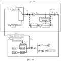
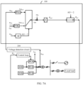
- FIG. 8A is a diagram of yet another control architecture of an energy storage system according to an embodiment of this application.
- three PCSs are still used as an example for description, which are respectively a PCS 1, a PCS 2, and a PCS 3.
- An output terminal of the PCS 1 is connected to a first side of a first transformer T1
- an output terminal of the PCS 2 is connected to a first side of a second transformer T2
- an output terminal of the PCS 3 is connected to a first side of a third transformer T3.
- a second side of T1, a second side of T2, and a second side of T3 are connected in parallel to connect to the alternating current power grid.
- each PCS the output terminal of each PCS is not directly connected together, but is connected to an alternating current power grid through its own corresponding transformer. Therefore, a distance between each PCS and a parallel connection point may be different, a distance difference causes a different line impedance, and a generated voltage drop varies with the line impedance. Further, a power grid voltage detected by each PCS is different. As a result, an islanding moment of the power grid that is determined by each PCS is different. However, by using the technical solutions provided in the embodiments of this application, each PCS obtains a reference angle. When islanding occurs, an angle of an output voltage of the PCS is made consistent with the reference angle. Therefore, even if it is determined that an islanding moment is different, no relatively large difference exists between the angles of the output voltages. Therefore, there is no relatively large cross current between the PCSs.
- an embodiment of this application further provides an on/off-grid switching method for an energy storage system.
- the following describes the on/off-grid switching method in detail with reference to accompanying drawings.
- FIG. 8 is a flowchart of an on/off-grid switching method for an energy storage system according to an embodiment of this application.
- the on/off-grid switching method for an energy storage system is applied to an energy storage system.
- the energy storage system includes at least two power conversion systems PCSs, output terminals of the at least two PCSs are connected in parallel to connect to an alternating current power grid, and input terminals of the at least two PCSs are connected to an energy storage power supply.
- the method is applicable to a first PCS in the at least two PCSs, and the first PCS is any one of the at least two PCSs.
- the method includes the following steps.
- the method is applicable to any PCS, and a controller of each PCS performs the same method.
- Each PCS may obtain the power grid voltage at the parallel connection point, to independently determine whether islanding occurs in the alternating current power grid.
- the PCS is required to supply power to the local load.
- the PCS operates on grid, the PCS is equivalent to a current source.
- the PCS operates off grid, the PCS needs to be equivalent to a voltage source and provide electric energy for the local load.
- a controller of each PCS obtains an angular frequency in real time by performing phase locking on the power grid voltage.
- the reference angle is obtained based on the angular frequency.
- the reference angle has no effect when no islanding occurs in the power grid, and plays a role only in an on/off-grid switching process.
- each PCS when the power grid voltage is normal, each PCS operates normally on grid, and each PCS obtains the reference angle based on the angular frequency of the power grid voltage.
- each PCS adjusts the angle of its own output voltage to the respective obtained reference angle. Because the reference angle obtained by each PCS is obtained by performing phase locking on the power grid voltage when the alternating current power grid is normal, the reference angle obtained by each PCS is the same.
- each PCS switches the angle of the output voltage to the reference angle, that is, the angle of the output voltage is made consistent with the reference angle. This ensures that the angle of the output voltage of each PCS is the same, thereby suppressing a relatively large cross current between the PCSs, and ensuring that each PCS can supply stable power to the local load.
- FIG. 9 is a flowchart of another on/off-grid switching method for an energy storage system according to an embodiment of this application.
- filtering may alternatively be directly performed on the phase-locked angular frequency, summation is performed on an angular frequency obtained after the filtering and the reference angular frequency, and then integration is performed on an angular frequency obtained through the summation, to obtain the reference angle.
- filtering may alternatively be directly performed on the phase-locked angular frequency, summation is performed on an angular frequency obtained after the filtering and the reference angular frequency, and then integration is performed on an angular frequency obtained through the summation, to obtain the reference angle.
- FIG. 4A refer to the control architecture shown in FIG. 4A .
- the angular frequency may be attenuated after the filtering, and an error may increase with time.
- the reference angle obtained after the integration may also have an error. Therefore, the reference angle may be corrected at a scheduled time to compensate for the error of the reference angle.
- the reference angle may be corrected by using the phase of the power grid voltage, and when islanding occurs in the alternating current power grid, an angle of an output voltage is adjusted to a corrected reference angle.
- a specific correction process is as follows: The reference angle is zeroed out at a zero crossing point of the phase of the power grid voltage, and the corrected reference angle is obtained by re-performing filtering and then integration on the phase-locked angular frequency of the power grid voltage. The reference angle is zeroed out at each zero crossing point of the phase of the power grid voltage. Therefore, the reference angle is a periodic (0° to 360°) sawtooth wave, that is, an alternating current signal.
- the angular frequency of the power grid voltage is specifically obtained as follows: Coordinate transformation is performed on the power grid voltage to obtain a Q-axis component in a rotating coordinate system, and phase locking is performed on the Q-axis component to obtain an angular frequency.
- the filtering may be low-pass filtering or sliding average filtering.
- each PCS switches an angle of its own output voltage to the reference angle, and performs on/off-grid switching.
- an angular frequency adjustment amount is 0, and the reference angle is directly zeroed out and corrected at a zero crossing point of a phase obtained after integration is performed on the reference angular frequency.
- the voltage at the parallel connection point of the power conversion systems is collected in real time.
- the collected voltage signal passes through a phase-locked loop, to obtain the angular frequency adjustment amount.
- An output angle is obtained by performing integration on the angular frequency obtained based on a sum of the angular frequency adjustment amount and the reference angular frequency, and the output angle is input to a PCS control loop for on-grid control.
- filtering and integration are performed on the angular frequency, and then correction is performed to obtain the corrected reference angle. Because the plurality of PCSs have a same parallel connection point, a reference angle of each PCS is the same.
- the angular frequency adjustment amount is switched to 0, and in addition, the angle of the output voltage of each PCS is made consistent with the reference angle. After they are consistent, it is ensured that the angle of the output voltage of each PCS is the same, and then the angle is input to the PCS control loop for off-grid control.
- an embodiment of this application further provides a power conversion system PCS.
- the power conversion system is disposed in an energy storage system, and the energy storage system includes a plurality of PCSs. Output terminals of the plurality of PCSs are connected in parallel to connect to an alternating current power grid.
- the alternating current power grid is normal, the plurality of PCSs operates normally on grid.
- the plurality of PCSs need to operate off grid to continue to supply power to a local load.
- the PCS provided in this embodiment of this application is applicable to each PCS in the energy storage system.
- the following describes the PCS from a perspective of one PCS, and an on/off-grid control process of each PCS is the same.
- FIG. 10 is a schematic diagram of a power conversion system according to an embodiment of this application.
- the power conversion system PCS provided in this embodiment of this application is a first PCS in at least two PCSs, the first PCS is any one of the at least two PCSs, and output terminals of the at least two PCSs are connected in parallel to connect to an alternating current power grid.
- the first PCS includes a voltage detection circuit 101, a power conversion circuit 102, and a controller 103.
- the power conversion circuit 102 is configured to: convert, in an on-grid state under control by the controller 103, electric energy provided by an energy storage power supply, and output converted electric energy to the alternating current power grid.
- the voltage detection circuit 101 is configured to detect a power grid voltage at a parallel connection point of the output terminals of the at least two PCSs.
- the controller 103 is configured to: when determining, based on the power grid voltage at the parallel connection point, that islanding occurs in the alternating current power grid, adjust an angle of an output voltage of the first PCS to a reference angle, so that angles of output voltages of the at least two PCSs are the same, where the reference angle is obtained by the first PCS based on an angular frequency of the power grid voltage when the at least two PCSs are on grid, and reference angles obtained by the at least two PCSs are the same.
- the controller is specifically configured to: when the at least two PCSs are on-grid, obtain the phase-locked angular frequency of the power grid voltage, perform integration on the sum of the angular frequency and the reference angular frequency to obtain a phase of the power grid voltage, and correct the reference angle by using the phase of the power grid voltage; and when islanding occurs in the alternating current power grid, adjust the angle of the output voltage to a corrected reference angle.
- Embodiment 9 The energy storage system according to any one of embodiment s 1 to 8, wherein a waveform of the reference angle is a sawtooth wave, and an angle of the sawtooth wave varies from 0 degrees to 360 degrees with a sine wave.
Landscapes
- Engineering & Computer Science (AREA)
- Power Engineering (AREA)
- Supply And Distribution Of Alternating Current (AREA)
- Inverter Devices (AREA)
Abstract
Description
- This application relates to the field of power system technologies, and in particular, to an energy storage system, an on/off-grid switching method, and a power conversion system.
- With aggravation of global environmental pollution, green energy resources, such as photovoltaic power, wind power, and hydro power, are becoming more and more popular. To better implement cooperation between an energy storage system and a power grid, the energy storage system may participate in various adjustment tasks (such as reactive power adjustment) of the power grid through grid connection.
- Usually, the energy storage system includes a plurality of power conversion systems (PCS, Power Conversion System), and output terminals of the plurality of PCSs are connected in parallel to connect to the power grid. To enable the PCS to participate in the adjustment tasks of the power grid, the PCS operates in a current source mode. A characteristic of a current source is as follows: When on-grid, the PCS actively detects a frequency and a phase of a power grid voltage, and controls its own output current based on the frequency and the phase of the power grid voltage. An internal impedance is characterized by a high value.
- The energy storage system usually has a local load. When a fault occurs on the power grid, the PCS needs to be switched from an on-grid mode to an off-grid mode to supply power to the local load. This is referred to as on/off-grid switching of the PCS for short. In an on/off-grid switching process, considering reliability and stability of power supply to the load, the PCS needs to ensure as much as possible that a current provided to the load is not abruptly changed, so as to implement seamless on/off-grid switching
- In a case of on/off-grid switching caused by an exception of the power grid, there is no communication between the plurality of PCSs. Each PCS independently detects the power grid voltage and independently performs on/off-grid switching, and angles of output voltages of the plurality of PCSs tend to vary greatly. Consequently, a large cross current occurs between the PCSs, seamless on/off-grid switching cannot be implemented, and the power supply to the load is affected.
- To resolve the foregoing technical problems, this application provides an energy storage system, an on/off-grid switching method, and a power conversion system, so that when PCSs perform on/off-grid switching, angles of output voltages of the PCSs are the same, thereby suppressing a relatively large cross current between the PCSs during on/off-grid switching, and supplying stable power to a local load.
- An embodiment of this application provides an energy storage system, including a plurality of PCSs. Output terminals of the plurality of PCSs are connected in parallel to connect to an alternating current power grid. Input terminals of the plurality of PCSs are connected to an energy storage power supply. For example, there are at least two PCSs, and without communicating with each other, the at least two PCSs independently collect a power grid voltage at a parallel connection point, and independently implement on/off-grid switching. On/Off-grid switching principles of the PCSs are the same. To be specific, a first PCS of the at least two PCSs includes a voltage detection circuit, a power conversion circuit, and a controller. The first PCS is any one of the at least two PCSs. The power conversion circuit converts, in an on-grid state, electric energy provided by the energy storage power supply, and outputs converted electric energy to the alternating current power grid. The voltage detection circuit detects a power grid voltage at a parallel connection point of output terminals of the at least two PCSs. When determining, based on the power grid voltage at the parallel connection point, that islanding occurs in the alternating current power grid, the controller adjusts an angle of an output voltage of the first PCS to a reference angle. Because the reference angle is obtained by the first PCS based on an angular frequency of the power grid voltage when the at least two PCSs are on-grid, angles of output voltages of the at least two PCSs are the same. In this way, when performing on/off-grid switching, the plurality of PCSs switch angles of output voltages to a same reference angle, so that phases of the output voltages are the same. Therefore, no large cross current is caused by a phase difference, that is, asynchronization, between the PCSs, and stable power can be supplied to a local load. It should be understood that, during on/off-grid switching, an angle of an output voltage of each PCS is synchronized with an angle of an output current, that is, the angle of the output voltage becomes consistent with the angle of the output current.
- To resolve a problem of a relatively large cross current between the plurality of PCSs during on/off-grid switching, in the energy storage system provided in this embodiment of this application, when the plurality of PCSs work normally on grid, the output terminals of the plurality of PCSs are connected to the alternating current power grid, so that an angular frequency of a power grid voltage can be obtained in real time, and the reference angle can be obtained by using the angular frequency of the power grid voltage. When the alternating current power grid is abnormal, the plurality of PCSs need to operate off grid, that is, switch from on-grid to off-grid. This is simply referred to as on/off-grid switching. Each PCS adjusts the angle of its own output voltage to the reference angle. When on-grid, all the PCSs are connected to the alternating current power grid, and obtained reference angles each are obtained based on the power grid voltage. Therefore, the reference angles obtained by all the PCSs are the same. When each PCS adjusts the angle of the output voltage to the reference angle, it can be ensured that the angles of the output voltages of all the PCSs are the same, that is, are the reference angle. Therefore, there is no problem of different angles of output voltages between the plurality of PCSs, and there is no relatively large cross current between the plurality of PCSs. In this way, when off-grid, the plurality of PCSs can ensure stable power supply to the local load.
- In a possible implementation, the controller is specifically configured to: when the alternating current power grid is normal, that is, when at least two PCSs are on-grid, perform phase locking on the power grid voltage to obtain the angular frequency of the power grid voltage; and then perform filtering (for example, low-pass filtering or sliding average filtering) on a phase-locked angular frequency, and perform integration on an angular frequency obtained after the filtering, to obtain the reference angle. When islanding occurs in the power grid, the power grid voltage may encounter a large angular frequency jump. To continue to supply stable power to the local load, the PCS needs to provide the local load with a phase existing before the jump of the power grid voltage. Therefore, filtering is intended to make the angular frequency change slowly. To be specific, when an input angular frequency encounters a transient change, an output angular frequency remains unchanged as far as possible. In this way, when the PCS is off-grid, an abrupt change of the angular frequency is turned into a slow change, thereby eliminating impact of a transient state. In addition, filtering can also filter out an interfering signal.
- The following describes two different manners of obtaining the reference angle. To be specific, filtering may be first performed on an angular frequency, and a sum of an angular frequency obtained after the filtering and a reference angular frequency is then obtained; or a sum of an angular frequency and a reference angular frequency may be first obtained, and filtering is then performed on the sum.
- In a first manner, when each PCS is on-grid, the controller performs coordinate transformation on the power grid voltage to obtain a Q-axis component in a rotating coordinate system, performs phase locking on the Q-axis component to obtain an angular frequency, performs low-pass filtering on a sum of the angular frequency and the reference angular frequency, and performs integration on an angular frequency obtained after the low-pass filtering to obtain the reference angle.
- In a second manner, in the on-grid state, the controller performs coordinate transformation on the power grid voltage to obtain a Q-axis component in a rotating coordinate system, performs phase locking on the Q-axis component to obtain an angular frequency, performs low-pass filtering on the angular frequency, and performs integration on a sum of the reference angular frequency and an angular frequency obtained after the low-pass filtering to obtain the reference angle.
- In a possible implementation, the controller is further configured to: obtain a phase of the power grid voltage when the at least two PCSs are on-grid, and correct the reference angle by using the phase of the power grid voltage; and when islanding occurs in the alternating current power grid, adjust the angle of the output voltage to a corrected reference angle.
- In a possible implementation, when the at least two PCSs are on-grid, the controller obtains the phase-locked angular frequency of the power grid voltage, and performs integration on a sum of the angular frequency and the reference angular frequency to obtain the phase of the power grid voltage.
- In a possible implementation, when the controller performs filtering on the sum of the angular frequency and the reference angular frequency, the angular frequency may be attenuated after the filtering, and an error may increase with time. The reference angle obtained after the integration may also have an error. Therefore, the reference angle may be corrected at a scheduled time to compensate for the error of the reference angle. That is, the controller zeroes out the reference angle at a zero crossing point of the phase of the power grid voltage, and obtains the corrected reference angle by re-performing filtering and then integration on the phase-locked angular frequency of the power grid voltage.
- In a possible implementation, the controller is further configured to: when the at least two PCSs are on-grid, use the phase of the power grid voltage as the angle of the output voltage of the first PCS.
- In a possible implementation, a waveform of the reference angle is a sawtooth wave, and an angle of the sawtooth wave varies from 0 degrees to 360 degrees with a sine wave.
- In a possible implementation, the controller detects a frequency or an amplitude of the power grid voltage at the parallel connection point, and when the frequency of the power grid voltage at the parallel connection point exceeds a preset frequency range or the amplitude of the power grid voltage at the parallel connection point exceeds a preset amplitude range, determines that islanding occurs in the alternating current power grid; and the controller is further configured to: when determining that islanding occurs in the alternating current power grid, set an islanding flag bit to 1, and set an angular frequency adjustment amount to 0, and is further configured to: when determining that a grid connection circuit breaker is disconnected, set the islanding flag bit to 2, and set the angular frequency adjustment amount based on a power angle characteristic, so that each PCS implements equal power division, where the grid connection circuit breaker is connected between the parallel connection point and the alternating current power grid.
- Based on the energy storage system described in the foregoing embodiment, an embodiment of this application further provides an on/off-grid switching method for an energy storage system. The energy storage system includes at least two power conversion systems PCSs, output terminals of the at least two PCSs are connected in parallel to connect to an alternating current power grid, and input terminals of the at least two PCSs are connected to an energy storage power supply; and the method is applicable to a first PCS in the at least two PCSs, the first PCS is any one of the at least two PCSs, and the method includes the following steps: detecting a power grid voltage at a parallel connection point of the output terminals of the at least two PCSs; and when determining, based on the power grid voltage at the parallel connection point, that islanding occurs in the alternating current power grid, adjusting an angle of an output voltage of the first PCS to a reference angle, so that angles of output voltages of the at least two PCSs are the same, where the reference angle is obtained by the first PCS based on an angular frequency of the power grid voltage when the at least two PCSs are on-grid.
- In a possible implementation, the method further includes: obtaining, when the at least two PCSs are on-grid, the reference angle by performing filtering and then integration on a phase-locked angular frequency of the power grid voltage.
- In a possible implementation, the obtaining, when the at least two PCSs are on-grid, the reference angle by performing filtering and then integration on a phase-locked angular frequency of the power grid voltage specifically includes:
when on-grid, performing coordinate transformation on the power grid voltage to obtain a Q-axis component in a rotating coordinate system, performing phase locking on the Q-axis component to obtain an angular frequency, performing low-pass filtering on a sum of the angular frequency and a reference angular frequency, and performing integration on an angular frequency obtained after the low-pass filtering to obtain the reference angle. - In a possible implementation, the obtaining, when the at least two PCSs are on-grid, the reference angle by performing filtering and then integration on a phase-locked angular frequency of the power grid voltage specifically includes:
when on-grid, performing coordinate transformation on the power grid voltage to obtain a Q-axis component in a rotating coordinate system, performing phase locking on the Q-axis component to obtain an angular frequency, performing low-pass filtering on the angular frequency, and performing integration on a sum of a reference angular frequency and an angular frequency obtained after the low-pass filtering to obtain the reference angle. - In a possible implementation, the method further includes: obtaining a phase of the power grid voltage when the at least two PCSs are on-grid, and correcting the reference angle by using the phase of the power grid voltage; and when islanding occurs in the alternating current power grid, adjusting the angle of the output voltage to a corrected reference angle.
- In a possible implementation, the obtaining a phase of the power grid voltage when the at least two PCSs are on-grid specifically includes: when the at least two PCSs are on-grid, obtaining the phase-locked angular frequency of the power grid voltage, and performing integration on a sum of the angular frequency and the reference angular frequency to obtain the phase of the power grid voltage.
- In a possible implementation, the correcting the reference angle by using the phase of the power grid voltage specifically includes: zeroing out the reference angle at a zero crossing point of the phase of the power grid voltage, and obtaining the corrected reference angle by re-performing filtering and then integration on the phase-locked angular frequency of the power grid voltage.
- An embodiment of this application further provides a power conversion system. The power conversion system PCS is a first PCS in at least two PCSs, the first PCS is any one of the at least two PCSs, and output terminals of the at least two PCSs are connected in parallel to connect to an alternating current power grid. The first PCS includes a voltage detection circuit, a power conversion circuit, and a controller. The power conversion circuit is configured to: convert, in an on-grid state, electric energy provided by an energy storage power supply, and output converted electric energy to the alternating current power grid. The voltage detection circuit is configured to detect a power grid voltage at a parallel connection point of the output terminals of the at least two PCSs. The controller is configured to: when determining, based on the power grid voltage at the parallel connection point, that islanding occurs in the alternating current power grid, adjust an angle of an output voltage of the PCS to a reference angle, so that angles of output voltages of the at least two PCSs are the same, where the reference angle is obtained by the first PCS based on an angular frequency of the power grid voltage when the at least two PCSs are on-grid.
- The power conversion system provided in this embodiment of this application collects the voltage at the parallel connection point in real time. In the on-grid state, the collected voltage signal passes through a phase-locked loop, to obtain an angular frequency adjustment amount. An output angle is obtained by performing integration on an angular frequency obtained based on a sum of the angular frequency adjustment amount and a reference angular frequency, and the output angle is input to a PCS control loop for on-grid control. In addition, filtering and integration are performed on the angular frequency, and then correction is performed to obtain a corrected reference angle. Because the plurality of PCSs have a same parallel connection point, a reference angle of each PCS is the same. When it is determined that islanding occurs, the angular frequency adjustment amount is switched to 0, and in addition, the angle of the output voltage of each PCS is made consistent with the reference angle. After they are consistent, it is ensured that the angle of the output voltage of each PCS is the same, and then the angle is input to the PCS control loop for off-grid control.
- In a possible implementation, the controller is specifically configured to: perform, in the on-grid state, coordinate transformation on the power grid voltage to obtain a Q-axis component in a rotating coordinate system, perform phase locking on the Q-axis component to obtain an angular frequency, perform low-pass filtering on a sum of the angular frequency and a reference angular frequency, and perform integration on an angular frequency obtained after the low-pass filtering to obtain the reference angle.
- In a possible implementation, the controller is specifically configured to: when the at least two PCSs are on-grid, obtain the phase-locked angular frequency of the power grid voltage, perform integration on a sum of the angular frequency and the reference angular frequency to obtain a phase of the power grid voltage, and correct the reference angle by using the phase of the power grid voltage; and when islanding occurs in the alternating current power grid, adjust the angle of the output voltage to a corrected reference angle.
- In a possible implementation, the controller zeroes out the reference angle at a zero crossing point of the phase of the power grid voltage, and obtains the corrected reference angle by re-performing filtering and then integration on the phase-locked angular frequency of the power grid voltage.
- When it is detected that islanding occurs in the alternating current power grid, in an on/off-grid switching process, the angular frequency adjustment amount is 0, and correction is performed on the reference angle by using a zero crossing point of a phase obtained after integration is performed on the reference angular frequency, so that the reference angle is zeroed out and corrected at the zero crossing point of the phase. In other words, in the on/off-grid switching process, the angular frequency does not need to be adjusted, and the angular frequency adjustment amount output by the phase-locked loop PLL has no effect anymore. In this case, the angular frequency no longer changes. The reference angle is corrected only by using the phase obtained after integration is performed on the reference angular frequency (for example, 50 Hz), to ensure that the angle of the output voltage of each PCS is made consistent with a same reference angle although each PCS determines islanding at a different moment, thereby ensuring that the angles of the output voltages of the plurality of PCSs are synchronous.
- This application has at least the following advantages:
- The output terminals of the plurality of PCSs in the energy storage system provided in the embodiments of this application are connected in parallel to connect to the alternating current power grid. When the power grid voltage is normal, each PCS operates normally on grid. When on-grid, each PCS performs phase locking on the power grid voltage to obtain the angular frequency, and obtains the reference angle based on the angular frequency and reserves the reference angle for use. When islanding occurs in the alternating current power grid, each PCS adjusts the angle of the output voltage to the respective obtained reference angle. Because the reference angle obtained by each PCS is obtained by performing phase locking on the power grid voltage when the alternating current power grid is normal, the reference angle obtained by each PCS is the same. When islanding occurs, each PCS switches the angle of the output voltage to the respective obtained reference angle, that is, the angles of the output voltages of all the PCSs are made consistent with the reference angle. This ensures that the angle of the output voltage of each PCS is the same, thereby suppressing a relatively large cross current beween the PCSs, and ensuring that each PCS can supply stable power to the local load during on/off-grid switching.
-
-
FIG. 1 is a schematic diagram of an energy storage system according to an embodiment of this application; -
FIG. 2 is a schematic diagram of direct current coupling of optical storage according to an embodiment of this application; -
FIG. 3 is a diagram of a control architecture of an energy storage system according to an embodiment of this application; -
FIG. 4A is a diagram of another control architecture of an energy storage system according to an embodiment of this application; -
FIG. 4B is a diagram of still another control architecture of an energy storage system according to an embodiment of this application; -
FIG. 5 is a diagram of waveforms of a power grid voltage and a reference angle according to an embodiment of this application; -
FIG. 6 is a schematic diagram of control during on/off-grid switching according to an embodiment of this application; -
FIG. 7A is a schematic diagram of off-grid control after on/off-grid switching according to an embodiment of this application; -
FIG. 7B is a schematic diagram of another energy storage system according to an embodiment of this application; -
FIG. 8 is a flowchart of an on/off-grid switching method for an energy storage system according to an embodiment of this application; -
FIG. 9 is a flowchart of another on/off-grid switching method for an energy storage system according to an embodiment of this application, and -
FIG. 10 is a schematic diagram of a power conversion system according to an embodiment of this application. - The following describes the technical solutions in embodiments of this application with reference to the accompanying drawings in embodiments of this application.
- The terms such as "first" and "second" in the description below are used only for the purpose of description and cannot be understood as indicating or implying relative importance or implicitly indicating a quantity of technical features indicated. Therefore, a feature limited by "first" or "second" may explicitly or implicitly include one or more features. In the description of this application, unless otherwise specified, a plurality of means two or more than two.
- In this application, unless otherwise expressly specified and limited, the term "connection" should be understood in a broad sense. For example, "connection" may be a fixed connection, a detachable connection, or an integrated connection, or may be a direct connection or an indirect connection through an intermediate medium. In addition, the term "coupling" may be a manner of implementing electrical connection of signal transmission. "Coupling" may be a direct electrical connection, or may be an indirect electrical connection through an intermediate medium.
- To enable a person skilled in the art to better understand the technical solutions provided in the embodiments of this application, the following first describes an application scenario of the technical solutions. This embodiment of this application relates to an energy storage system. The energy storage system may operate on grid, and may supply power to a load together with an alternating current power grid. When a fault occurs in the alternating current power grid, the energy storage system may supply power to the load independently. A specific application scenario of the energy storage system is not limited in this embodiment of this application, for example, may be a large-scale energy storage application scenario, a small/medium-scale distributed energy storage application scenario, or a home energy storage application scenario.
-
FIG. 1 is a schematic diagram of an energy storage system according to an embodiment of this application. - The energy storage system usually includes a plurality of PCSs. As shown in
FIG. 1 , n PCSs are included, where n is a positive integer greater than or equal to 2. The n PCSs are respectively aPCS 1 to a PCS n. An input terminal of each PCS is connected to the energy storage system (ESS, Energy Storage System). Each PCS may be connected to one ESS, or may be connected to a plurality of ESSs. For example, thePCS 1 is connected to one ESS, and the PCS n is connected to one ESS. This is not specifically limited in this embodiment of this application, and may be set based on an actual requirement. For example, for an optical storage system, the ESS may be an energy storage container, and electric energy in a battery cluster in the energy storage container may be obtained through photovoltaic power. For example, the ESS may include a photovoltaic module, a battery system, a direct current-direct current converter, and the like. The plurality of PCSs may be separately connected to a first side of a transformer, or the plurality of PCSs may be connected to the first side of the transformer through alternating current coupling. A second side of the transformer is connected to an on-grid switch. The on-grid switch may be specifically implemented by using a grid connection circuit breaker. - In addition, the optical storage system includes coupling between photovoltage and energy storage.
FIG. 2 is a schematic diagram of optical storage-to-direct current coupling according to an embodiment of this application. A direct current power supply of the ESS may alternatively come from wind power, hydro power, a battery, or the like. - To be specific, the ESS in
FIG. 1 may include a battery BAT, a photovoltaic module PV, and direct current/direct current (DC/DC, Direct Current) circuits inFIG. 2 , that is, the BAT is connected to a corresponding DC/DC circuit, the PV is connected to a corresponding DC/DC circuit, and all output terminals are connected in parallel. - A PPC in
FIG. 1 is a power plant controller or a host computer. The PPC is configured to control an open or closed status of the grid connection circuit breaker, for example, control the grid connection circuit breaker to be disconnected or connected. When the alternating current power grid is normal, the PPC controls the grid connection circuit breaker to be connected, and the PCS is connected to the alternating current power grid for on-grid operation. Load is a local load. When the alternating current power grid is abnormal, for example, when islanding occurs, the PPC controls the grid connection circuit breaker to be disconnected. The PCS is disconnected from the alternating current power grid, operates off grid, and supplies power to the local load Load. - When the PCS operates on grid, the PCS operates in a current source mode. When the alternating current power grid fails and trips, the energy storage system needs to switch to operate off grid, to supply power to the local load. Therefore, the PCS needs to operate in a voltage source mode, to provide a stable voltage for the local load.
- Because there is no communication between the plurality of PCSs, each PCS independently performs sampling, independently determines, based on a power grid voltage, whether islanding occurs, and performs off-grid control when islanding occurs. Because a cable length between a voltage detection circuit of each PCS and a parallel connection point varies, a line impedance varies with the cable length, and a generated voltage drop varies with the line impedance. Further, a power grid voltage detected by each PCS is different. As a result, an islanding moment of the power grid that is determined by each PCS is different. Further, a moment at which each PCS switches from on-grid to off-grid is different, and an output angle varies greatly. This causes a large cross current and affects stability of power supply to the local load.
- To resolve a problem of a relatively large cross current between the plurality of PCSs during on/off-grid switching, in the energy storage system provided in this embodiment of this application, when the plurality of PCSs work normally on grid, the output terminals of the plurality of PCSs are connected to the alternating current power grid, so that an angular frequency of the power grid voltage can be obtained in real time, and a reference angle can be obtained by using the angular frequency of the power grid voltage. When the alternating current power grid is abnormal, the plurality of PCSs need to operate off grid, that is, switch from on-grid to off-grid. This is simply referred to as on/off-grid switching. Each PCS adjusts an angle of its own output voltage to the reference angle. When on-grid, all the PCSs are connected to the alternating current power grid, and obtained reference angles each are obtained based on the power grid voltage. Therefore, the reference angles obtained by all the PCSs are the same. When each PCS adjusts the angle of the output voltage to the reference angle, it can be ensured that the angles of the output voltages of all the PCSs are the same, that is, are the reference angle. Therefore, there is no problem of different angles of output voltages between the plurality of PCSs, and there is no relatively large cross current between the plurality of PCSs. In this way, when off-grid, the plurality of PCSs can ensure stable power supply to the local load.
- To enable a person skilled in the art to better understand the technical solutions provided in the embodiments of this application, the following describes in detail the technical solutions provided in the embodiments of this application with reference to the accompanying drawings.
-
FIG. 3 is a diagram of a control architecture of an energy storage system according to an embodiment of this application. - The energy storage system provided in this embodiment of this application includes at least two power conversion systems PCSs, and output terminals of the at least two PCSs are connected in parallel to connect to an alternating current power grid.
FIG. 3 only shows three PCSs schematically. A specific quantity of PCSs is not limited in this embodiment of this application. Input terminals of the three PCSs are connected to an energy storage power supply. The energy storage power supply may come from photovoltaic power, wind power, hydro power, or a battery. That is, the ESS outputs a direct current, and the PCS may convert the direct current into an alternating current same as that in the power grid. An input terminal of each PCS may be connected to an independent ESS, or a plurality of PCSs may be connected to one same ESS. - In the energy storage system provided in this embodiment of this application, the plurality of PCSs independently complete on/off-grid switching without being controlled by another device. Synchronization is not required between the plurality of PCSs, that is, the plurality of PCSs do not need to send an off-grid synchronization signal to each other.
- In this embodiment of this application, each PCS independently completes its own on/off-grid switching. Therefore, for each PCS, an on/off-grid switching principle is the same. For ease of description, any one of the plurality of PCSs is used as an example below for description, and another PCS has the same on/off-grid control principle. Details are not described herein. For ease of description, a first PCS is used to represent any one of the plurality of PCSs.
- The first PCS includes a
voltage detection circuit 200, a power conversion circuit (that is, a PCS in the figure), and acontroller 100. The power conversion circuit is configured to: convert, in an on-grid state, electric energy provided by the energy storage power supply, and output converted electric energy to the alternating current power grid. - The
voltage detection circuit 200 is configured to detect a power grid voltage at a parallel connection point of the output terminals of the at least two PCSs. - The parallel connection point is a point at which the output terminals of the plurality of PCSs are connected in parallel. In the figure, the output terminals of the PCSs are connected to a first side of a transformer, and a second side of the transformer is connected to the alternating current power grid. In this case, the parallel connection point is a point at which the PCSs are connected to the first side of the transformer.
- The
controller 100 is configured to: when determining, based on the power grid voltage of the parallel connection point, that islanding occurs in the alternating current power grid, adjust an angle of an output voltage of the first PCS to a reference angle, so that angles of output voltages of the at least two PCSs are the same. The reference angle is obtained based on an angular frequency of the power grid voltage when the at least two PCSs are on-grid. It should be understood that, because the reference angle is obtained when the plurality of PCSs are normally on-grid, reference angles obtained by the at least two PCSs are the same. - If islanding occurs in the alternating current power grid, it indicates that the power grid is abnormal and cannot continue to normally supply power to a local load. In this case, the PCS is required to supply power to the local load. When the PCS operates on grid, the PCS is equivalent to a current source, and the alternating current power grid provides a stable voltage for the local load. When the PCS operates off grid, the PCS needs to be equivalent to a voltage source to provide electric energy for the local load, so that the PCS provides a stable voltage for the local load.
- It should be understood that, a control loop in the figure is also implemented by the
controller 100. - To facilitate understanding of a working principle of the
controller 100,FIG. 3 shows a control link inside thecontroller 100. - To facilitate understanding of the technical solutions provided in the embodiments of this application, the following first describes a control principle of a PCS when no islanding (transition) occurs in the alternating current power grid.
- A solid line in the
controller 100 represents a working process in a normal on-grid case, and a dashed line represents a working process of thecontroller 100 in a case that islanding occurs in the alternating current power grid. - First, a control process of on-grid working corresponding to the solid line in
FIG. 3 is described. - When the PCS works normally on grid, the
voltage detection circuit 200 detects a three-phase voltage uabc at the output terminal of the PCS. Coordinate transformation is performed to transform a static coordinate system into a Q-axis component of the voltage in a two-phase rotating coordinate system. Then, the Q-axis component passes through a phase-locked loop PLL to obtain an angular frequency adjustment amount Δωpll representing a rotational speed of the power grid voltage. The voltage in the rotating coordinate system is a vector, and the angular frequency is a frequency of rotation. In the on-grid state, the angular frequency adjustment amount Δω = Δωpll, that is, an angular frequency Δωpll output by the PLL and a reference angular frequency ωB (a fixed angular frequency of the power grid is 50 Hz or 60 Hz) are added. Integration is performed on a sum of the angular frequency Δωpll and the reference angular frequency ωB to obtain a phase θreal of the power grid voltage. In thefigure, 1 /s represents integration. In this case, the power grid is normal and no islanding occurs. Therefore, there is no islanding flag. In the figure, AI only indicates islanding detection. AI1 is an output signal of AI, and is an islanding flag bit representing the islanding flag. When AI1 is equal to 0, it indicates that the alternating current power grid is normal and no islanding occurs. This flag determines final θpcs for the control loop. Islanding detection may be determined by using the power grid voltage, or may be determined by using a power grid current. For example, if an amplitude or a frequency of the power grid voltage has an offset, and is excessively large or excessively small, it may be determined that islanding occurs in the power grid. If the power grid voltage is normal, it is determined that no islanding occurs, and the PCS operates normally on grid. In this case, θpcs is equal to θreal, that is, θreal is directly output to the control loop. The control loop herein refers to a control loop, for a power grid angle, that is required for the PCS to be on-grid, for example, a current loop, a voltage loop, or a power loop. The control loop controls the PCS to perform power control or voltage control. The foregoing control loops each are a control loop in a case that the PCS is normally on-grid. Details are not described herein. It should be understood that, the PCS works normally and performs voltage loop control, so as to detect its own output voltage. - In addition, when the PCS operates normally on grid, the controller of each PCS obtains an angular frequency in real time by performing phase locking on the power grid voltage. The reference angle is obtained based on the angular frequency. The reference angle has no effect when no islanding occurs in the power grid, and plays a role only in an on/off-grid switching process.
- At a moment when islanding occurs in the alternating current power grid, a PLL of each PCS may output a different angular frequency adjustment amount. Consequently, an angle of an output voltage of each PCS is different, and there is a phase difference between the PCSs. This causes a relatively large cross current in an off-grid state.
- The following describes a process, of switching from on-grid to off-grid, corresponding to the dashed line in
FIG. 3 . - When determining, based on the power grid voltage at the parallel connection point of the plurality of PCSs, that islanding occurs in the alternating current power grid, the controller adjusts the angle of the output voltage of the PCS to the reference angle. θB is assigned to θreal that is, θpcs used by the control loop at this time is equal to θB. The reference angle θB is obtained by the at least two PCSs in the on-grid state based on the angular frequency of the power grid voltage. Reference angles obtained by the at least two PCSs are the same.
- Each PCS independently implements on/off-grid switching. When on-grid, each PCS obtains an angular frequency of the power grid voltage in real time, and obtains a reference angle based on the angular frequency of the power grid voltage. Therefore, the reference angle obtained by each PCS is the same. When the PCS performs on/off-grid switching, each PCS switches to the respective obtained reference angle. Because the reference angle obtained by each PCS is the same, a large difference in the angles of the output voltages of the PCSs can be avoided, and a cross current between the PCSs can be further suppressed. It should be understood that, during on/off-grid switching, the angle of the output voltage of the PCS is the same as an angle of an output current, that is, the output voltage is synchronous with the output current.
- In an implementation, the controller obtains the reference angle based on the angular frequency of the power grid voltage by filtering, for example, low-pass filtering or sliding average filtering. When islanding occurs in the power grid, the power grid voltage may encounter a large angular frequency jump. To continue to supply stable power to the local load, the PCS needs to provide the local load with a phase existing before the jump of the power grid voltage. Therefore, filtering is intended to make the angular frequency change slowly. To be specific, when an input angular frequency encounters a transient change, an output angular frequency remains unchanged as far as possible. In this way, when the PCS is off-grid, an abrupt change of the angular frequency is turned into a slow change, thereby eliminating impact of a transient state. In addition, filtering can also filter out an interfering signal.
- In the energy storage system provided in this embodiment of this application, the output terminals of the plurality of PCSs are connected in parallel to connect to the alternating current power grid. When the power grid voltage is normal, each PCS operates normally on grid, and each PCS obtains the reference angle based on the angular frequency of the power grid voltage. When islanding occurs in the alternating current power grid, each PCS adjusts the angle of its own output voltage to the respective obtained reference angle. Because the reference angle obtained by each PCS is obtained by performing phase locking on the power grid voltage when the alternating current power grid is normal, the reference angle obtained by each PCS is the same. When islanding occurs, each PCS switches the angle of the output voltage to the reference angle, that is, the angle of the output voltage is made consistent with the reference angle. This ensures that the angle of the output voltage of each PCS is the same, thereby suppressing a relatively large cross current between the PCSs, and ensuring that each PCS can supply stable power to the local load.
- In addition, in the energy storage system provided in this embodiment of this application, all the PCSs can implement synchronization between the angles of the output voltages during on/off-grid switching, without relying on communication. Because the angles of the output voltages of all the PCSs are made consistent with the same reference angle, seamless switching is truly implemented in the on/off-grid switching process, and voltage distortion is small. Considering of a voltage tolerance capability of the local load during on/off-grid switching, in a switching transient process, for example, an amplitude of voltage distortion does not exceed 90% to 110% of a rated voltage as far as possible, and a phase jump is less than 5 degrees.
- For the reference angle described in the foregoing embodiment, a sum of the angular frequency adjustment amount and the reference angular frequency is first obtained, filtering is performed on the sum of the angular frequency adjustment amount and the reference angular frequency, and then integration is performed on an angular frequency obtained after the filtering, to obtain the reference angle. In addition, there is another possible implementation.
FIG. 4A is a diagram of another control architecture of an energy storage system according to an embodiment of this application. - The controller may first perform filtering on the angular frequency adjustment amount Δω, calculate a sum of the reference angular frequency and an angular frequency adjustment amount Δω1 obtained after the filtering, and then perform integration on the sum of the reference angular frequency ωB and the angular frequency adjustment amount Δω1 obtained after the filtering, to obtain the reference angle θB.
- It should be understood that, a manner of obtaining the reference angle shown in
FIG. 4A is applicable to all technical solutions provided in the embodiments of this application. For ease of description, the following embodiments are described by using the manner of obtaining the reference angle shown inFIG. 3 . - The following describes in detail a switching process in a case that islanding occurs in the alternating current power grid.
-
FIG. 4B is a diagram of still another control architecture of an energy storage system according to an embodiment of this application. - When the controller performs filtering on the sum of the angular frequency Δωpll and the reference angular frequency ωB, the angular frequency may be attenuated after the filtering, and an error may increase with time. The reference angle obtained after the integration may also have an error. Therefore, the reference angle may be corrected at a scheduled time to compensate for the error of the reference angle. The following describes a specific correction manner.
- The controller is further configured to: obtain a phase of the power grid voltage when the at least two PCSs are on-grid, and correct the reference angle by using the phase of the power grid voltage; and when islanding occurs in the alternating current power grid, adjust the angle of the output voltage to a corrected reference angle.
- A manner of obtaining the phase of the power grid voltage during normal on-grid operation is as follows: When the at least two PCSs are on-grid, the controller obtains a phase-locked angular frequency of the power grid voltage, and performs integration on a sum of the angular frequency and the reference angular frequency to obtain the phase of the power grid voltage, that is, θ real.
- A specific manner in which the controller corrects the reference angle θB by using θ real is as follows: The controller zeroes out the reference angle θB at a zero crossing point of the phase θ real of the power grid voltage, and obtains the corrected reference angle θB by re-performing filtering and then integration on the phase-locked angular frequency of the power grid voltage. The reference angle is zeroed out at each zero crossing point of θ real. Therefore, the reference angle is a periodic sawtooth wave. An angle of the sawtooth wave varies from 0 degrees to 360 degrees with a sine wave.
-
FIG. 5 is a diagram of waveforms of a power grid voltage and a reference angle according to an embodiment of this application; - A sine wave in
FIG. 5 is the waveform of the power grid voltage, and a sawtooth wave inFIG. 5 is the waveform of the reference angle provided in this embodiment of this application. - For example, islanding occurs in the alternating current power grid starting from a moment t1. That output terminals of two PCSs are connected in parallel is used as an example. An angle of an output voltage of a
PCS 1 is A, and an angle of an output voltage of aPCS 2 is B. It can be seen from the figure that, both A and B deviate from the sawtooth wave corresponding to the reference angle. When thePCS 1 and thePCS 2 determine that islanding occurs, the angle of the output voltage of thePCS 1 is adjusted to the reference angle, and the angle of the output voltage of thePCS 2 is adjusted to the reference angle, so that the angles of the output voltages of thePCS 1 and thePCS 2 are both the reference angle, and the angles of the output voltages of thePCS 1 and thePCS 2 are the same, thereby avoiding a relatively large cross current between thePCS 1 and thePCS 2 in parallel from occurring and from affecting stable power supply to the local load. - Correction of the reference angle by the controller is also performed when the PCS is normally on-grid, that is, the corrected reference angle is always obtained when the PCS is normally on-grid. The angle of the output voltage is switched to the corrected reference angle only upon on/off-grid switching.
- It should be understood that, the corrected reference angle obtained by each PCS is used only once during on/off-grid switching, that is, θB is assigned to θpcs. After the switching is completed subsequently, each PCS implements operation in the off-grid state.
-
FIG. 6 is a schematic diagram of control during on/off-grid switching according to an embodiment of this application. -
FIG. 6 andFIG. 4B are compared. InFIG. 4B , an islanding flag bit AI1 is 0, that is, no islanding has occurred, and the PCS operates in the on-grid state. InFIG. 6 , an islanding flag bitAI1 is 1, that is, islanding has occurred inFIG. 6 , and the PCS operates in a transition state of on/off-grid switching. - When AI determines that islanding occurs in the alternating current power grid, the islanding flag bit is set to 1, and the angular frequency adjustment amount becomes 0 at this time. That is, in the on/off-grid switching process, the angular frequency does not need to be adjusted, Δω = 0, and the angular frequency adjustment amount Δωpll output by the phase-locked loop PLL has no effect anymore. In this case, the angular frequency no longer changes. The reference angle θB is corrected only by using the phase obtained after integration is performed on the reference angular frequency ωB (for example, 50 Hz), that is, θpcs = θB, to ensure that the angle of the output voltage of each PCS is made consistent with a same reference angle although each PCS determines islanding at a different moment, thereby ensuring that the angles of the output voltages of the plurality of PCSs are synchronous.
- To complete the entire on/off-grid switching, a switching process may need to be maintained for a period of time, for example, dozens to hundreds of milliseconds, to wait for disconnection of all switches connected to the alternating current power grid, that is, disconnection from the alternating current power grid. After switch operations are reliably completed, the entire on/off-grid switching is completed.
- For the energy storage system provided in this embodiment of this application, the following is mainly described: a process in which when islanding occurs in the alternating current power grid, each PCS controls the angle of its own output voltage to be switched to the same reference angle, and performs off-grid control after the switching is completed. The off-grid control is not specifically described herein, that is, after the PCS is off grid, control of the angular frequency adjustment amount belongs to specific control over off-grid work.
-
FIG. 7 is a schematic diagram of off-grid control after on/off-grid switching according to an embodiment of this application. - In the energy storage system provided in this embodiment, after making the angle of its own output voltage consistent with the reference angle, each PCS completes on/off-grid switching. In this case, the islanding flag bit AI1 is set to 2, and an off-grid voltage-controlled VSG implements control over the PCS, and each PCS equally divides power to supply power to the local load. It should be noted that, the angular frequency adjustment amount is no longer 0 in this case, and the angular frequency starts to change again. The off-grid voltage-controlled VSG outputs an angular frequency adjustment amount ΔωVSG to perform off-grid control. That is, the controller is further configured to: when determining that a grid connection circuit breaker is disconnected, set the islanding flag bit AI1 to 2, and set an angular frequency adjustment amount based on a power angle characteristic, so that each PCS implements equal power division. The grid connection circuit breaker is connected between the parallel connection point and the alternating current power grid. It should be understood that, during off-grid control, in addition to an output voltage uabc of the PCS, the off-grid voltage-controlled VSG further needs an output current i abc of the PCS.
- The energy storage system provided in this embodiment of this application collects the voltage at the parallel connection point of the power conversion systems in real time. In the on-grid state, the collected voltage signal passes through the phase-locked loop, to obtain the angular frequency adjustment amount. An output angle is obtained by performing integration on the angular frequency obtained based on the sum of the angular frequency adjustment amount and the reference angular frequency, and the output angle is input to the PCS control loop for on-grid control. In addition, filtering and integration are performed on the angular frequency, and then correction is performed to obtain the corrected reference angle. Because the plurality of PCSs have a same parallel connection point, a reference angle of each PCS is the same. When it is determined that islanding occurs, the angular frequency adjustment amount is switched to 0, and in addition, the angle of the output voltage of each PCS is made consistent with the reference angle. After they are consistent, it is ensured that the angle of the output voltage of each PCS is the same, and then the angle is input to the PCS control loop for off-grid control.
- In the energy storage system described in the foregoing embodiments, the output terminals of the PCSs are connected in parallel directly, and then are connected to the alternating current power grid through the transformer. In addition, the technical solutions for on/off-grid switching provided in the foregoing embodiments of this application are further applicable to a case that the output terminal of each PCS is connected to a first side of one corresponding transformer, and second sides of the transformers are connected in parallel, that is, connected to a parallel connection point.
- FIG. 8A is a diagram of yet another control architecture of an energy storage system according to an embodiment of this application.
- In this embodiment, three PCSs are still used as an example for description, which are respectively a
PCS 1, aPCS 2, and a PCS 3. An output terminal of thePCS 1 is connected to a first side of a first transformer T1, an output terminal of thePCS 2 is connected to a first side of a second transformer T2, and an output terminal of the PCS 3 is connected to a first side of a third transformer T3. A second side of T1, a second side of T2, and a second side of T3 are connected in parallel to connect to the alternating current power grid. - In FIG. 8A, the output terminal of each PCS is not directly connected together, but is connected to an alternating current power grid through its own corresponding transformer. Therefore, a distance between each PCS and a parallel connection point may be different, a distance difference causes a different line impedance, and a generated voltage drop varies with the line impedance. Further, a power grid voltage detected by each PCS is different. As a result, an islanding moment of the power grid that is determined by each PCS is different. However, by using the technical solutions provided in the embodiments of this application, each PCS obtains a reference angle. When islanding occurs, an angle of an output voltage of the PCS is made consistent with the reference angle. Therefore, even if it is determined that an islanding moment is different, no relatively large difference exists between the angles of the output voltages. Therefore, there is no relatively large cross current between the PCSs.
- Based on the energy storage system provided in the foregoing embodiments, an embodiment of this application further provides an on/off-grid switching method for an energy storage system. The following describes the on/off-grid switching method in detail with reference to accompanying drawings.
-
FIG. 8 is a flowchart of an on/off-grid switching method for an energy storage system according to an embodiment of this application. - The on/off-grid switching method for an energy storage system provided in this embodiment is applied to an energy storage system. The energy storage system includes at least two power conversion systems PCSs, output terminals of the at least two PCSs are connected in parallel to connect to an alternating current power grid, and input terminals of the at least two PCSs are connected to an energy storage power supply. The method is applicable to a first PCS in the at least two PCSs, and the first PCS is any one of the at least two PCSs. The method includes the following steps.
- S801. Detect a power grid voltage at a parallel connection point of the output terminals of the at least two PCSs.
- The method is applicable to any PCS, and a controller of each PCS performs the same method. Each PCS may obtain the power grid voltage at the parallel connection point, to independently determine whether islanding occurs in the alternating current power grid.
- S802. When it is determined, based on the power grid voltage at the parallel connection point, that islanding occurs in the alternating current power grid, adjust an angle of an output voltage of the first PCS to a reference angle, so that angles of output voltages of the at least two PCSs are the same, where the reference angle is obtained by the first PCS based on an angular frequency of the power grid voltage when the at least two PCSs are on-grid, and reference angles obtained by the at least two PCSs are the same.
- If islanding occurs in the alternating current power grid, it indicates that the power grid is abnormal and cannot continue to normally supply power to a local load. In this case, the PCS is required to supply power to the local load. When the PCS operates on grid, the PCS is equivalent to a current source. When the PCS operates off grid, the PCS needs to be equivalent to a voltage source and provide electric energy for the local load.
- When the PCS operates normally on grid, a controller of each PCS obtains an angular frequency in real time by performing phase locking on the power grid voltage. The reference angle is obtained based on the angular frequency. The reference angle has no effect when no islanding occurs in the power grid, and plays a role only in an on/off-grid switching process.
- Based on the method provided in this embodiment of this application, when the power grid voltage is normal, each PCS operates normally on grid, and each PCS obtains the reference angle based on the angular frequency of the power grid voltage. When islanding occurs in the alternating current power grid, each PCS adjusts the angle of its own output voltage to the respective obtained reference angle. Because the reference angle obtained by each PCS is obtained by performing phase locking on the power grid voltage when the alternating current power grid is normal, the reference angle obtained by each PCS is the same. When islanding occurs, each PCS switches the angle of the output voltage to the reference angle, that is, the angle of the output voltage is made consistent with the reference angle. This ensures that the angle of the output voltage of each PCS is the same, thereby suppressing a relatively large cross current between the PCSs, and ensuring that each PCS can supply stable power to the local load.
-
FIG. 9 is a flowchart of another on/off-grid switching method for an energy storage system according to an embodiment of this application. - S901. Detect a power grid voltage at a parallel connection point of output terminals of at least two PCSs.
- S902. When it is determined, based on the power grid voltage, that an alternating current power grid is normal, obtain a phase-locked angular frequency of the power grid voltage, perform integration on a sum of the angular frequency and a reference angular frequency to obtain a phase of the power grid voltage, and perform on-grid control on the PCSs based on the phase of the power grid voltage; and further perform filtering on the sum of the phase-locked angular frequency and the reference angular frequency, and perform integration on an angular frequency obtained after the filtering, to obtain a reference angle.
- It should be understood that, filtering may alternatively be directly performed on the phase-locked angular frequency, summation is performed on an angular frequency obtained after the filtering and the reference angular frequency, and then integration is performed on an angular frequency obtained through the summation, to obtain the reference angle. For details, refer to the control architecture shown in
FIG. 4A . - In addition, the angular frequency may be attenuated after the filtering, and an error may increase with time. The reference angle obtained after the integration may also have an error. Therefore, the reference angle may be corrected at a scheduled time to compensate for the error of the reference angle. Specifically, the reference angle may be corrected by using the phase of the power grid voltage, and when islanding occurs in the alternating current power grid, an angle of an output voltage is adjusted to a corrected reference angle. A specific correction process is as follows: The reference angle is zeroed out at a zero crossing point of the phase of the power grid voltage, and the corrected reference angle is obtained by re-performing filtering and then integration on the phase-locked angular frequency of the power grid voltage. The reference angle is zeroed out at each zero crossing point of the phase of the power grid voltage. Therefore, the reference angle is a periodic (0° to 360°) sawtooth wave, that is, an alternating current signal.
- The angular frequency of the power grid voltage is specifically obtained as follows: Coordinate transformation is performed on the power grid voltage to obtain a Q-axis component in a rotating coordinate system, and phase locking is performed on the Q-axis component to obtain an angular frequency. The filtering may be low-pass filtering or sliding average filtering.
- S903. When it is determined, based on the power grid voltage, that islanding occurs in the alternating current power grid, each PCS switches an angle of its own output voltage to the reference angle, and performs on/off-grid switching.
- During a switching process, an angular frequency adjustment amount is 0, and the reference angle is directly zeroed out and corrected at a zero crossing point of a phase obtained after integration is performed on the reference angular frequency.
- According to the method provided in this embodiment of this application, the voltage at the parallel connection point of the power conversion systems is collected in real time. In an on-grid state, the collected voltage signal passes through a phase-locked loop, to obtain the angular frequency adjustment amount. An output angle is obtained by performing integration on the angular frequency obtained based on a sum of the angular frequency adjustment amount and the reference angular frequency, and the output angle is input to a PCS control loop for on-grid control. In addition, filtering and integration are performed on the angular frequency, and then correction is performed to obtain the corrected reference angle. Because the plurality of PCSs have a same parallel connection point, a reference angle of each PCS is the same. When it is determined that islanding occurs, the angular frequency adjustment amount is switched to 0, and in addition, the angle of the output voltage of each PCS is made consistent with the reference angle. After they are consistent, it is ensured that the angle of the output voltage of each PCS is the same, and then the angle is input to the PCS control loop for off-grid control.
- Based on the energy storage system and the on/off-grid switching method provided in the foregoing embodiments, an embodiment of this application further provides a power conversion system PCS. The power conversion system is disposed in an energy storage system, and the energy storage system includes a plurality of PCSs. Output terminals of the plurality of PCSs are connected in parallel to connect to an alternating current power grid. When the alternating current power grid is normal, the plurality of PCSs operates normally on grid. However, when islanding occurs in the alternating current power grid, the plurality of PCSs need to operate off grid to continue to supply power to a local load. However, because the plurality of PCSs may not simultaneously determine that islanding occurs, or moments at which the plurality of PCSs perform on/off-grid switching are different, angles of output voltages of the PCSs are different. In addition, the output terminals of the plurality of PCSs are connected in parallel. Consequently, a relatively large cross current occurs between the PCSs when the angles of the output voltages are different. For the PCSs provided in this embodiment of this application, when operating normally, each PCS can obtain a reference angle based on a phase of a power grid voltage, and the reference angle obtained by each PCS is the same. During on/off-grid switching, the angle is switched to the reference angle, so that the angles of the output voltages of the PCSs are the same reference angle. Therefore, a relatively large cross current can be suppressed in an on/off-grid switching process, and a stable voltage and current can be supplied to the local load. The PCS provided in this embodiment of this application is applicable to each PCS in the energy storage system. The following describes the PCS from a perspective of one PCS, and an on/off-grid control process of each PCS is the same.
- With reference to an accompanying drawing, the following describes in detail the PCS provided in this embodiment of this application.
-
FIG. 10 is a schematic diagram of a power conversion system according to an embodiment of this application. - The power conversion system PCS provided in this embodiment of this application is a first PCS in at least two PCSs, the first PCS is any one of the at least two PCSs, and output terminals of the at least two PCSs are connected in parallel to connect to an alternating current power grid. The first PCS includes a
voltage detection circuit 101, apower conversion circuit 102, and acontroller 103. - The
power conversion circuit 102 is configured to: convert, in an on-grid state under control by thecontroller 103, electric energy provided by an energy storage power supply, and output converted electric energy to the alternating current power grid. - The
voltage detection circuit 101 is configured to detect a power grid voltage at a parallel connection point of the output terminals of the at least two PCSs. - A specific implementation of the
voltage detection circuit 101 is not specifically limited in this embodiment of this application, for example, thevoltage detection circuit 101 may be implemented by a voltage sensor, or may be implemented by building a circuit. - The
controller 103 is configured to: when determining, based on the power grid voltage at the parallel connection point, that islanding occurs in the alternating current power grid, adjust an angle of an output voltage of the first PCS to a reference angle, so that angles of output voltages of the at least two PCSs are the same, where the reference angle is obtained by the first PCS based on an angular frequency of the power grid voltage when the at least two PCSs are on grid, and reference angles obtained by the at least two PCSs are the same. - If islanding occurs in the alternating current power grid, it indicates that the power grid is abnormal and cannot continue to normally supply power to a local load. In this case, the PCS is required to supply power to the local load. When the PCS operates on grid, the PCS is equivalent to a current source. When the PCS operates off grid, the PCS needs to be equivalent to a voltage source and provide electric energy for the local load.
- When the PCS operates normally on grid, a controller of each PCS obtains an angular frequency in real time by performing phase locking on the power grid voltage. The reference angle is obtained based on the angular frequency. The reference angle has no effect when no islanding occurs in the power grid, and plays a role only in an on/off-grid switching process.
- When the power grid voltage is normal, the PCS provided in this embodiment of this application obtains the reference angle based on the angular frequency of the power grid voltage. When islanding occurs in the alternating current power grid, the PCS adjusts the angle of its own output voltage to the respective obtained reference angle. Because the reference angle obtained by each PCS is obtained by performing phase locking on the power grid voltage when the alternating current power grid is normal, the reference angle obtained by each PCS is the same. When islanding occurs, each PCS switches the angle of the output voltage to the reference angle, that is, the angle of the output voltage is made consistent with the reference angle. This ensures that the angle of the output voltage of each PCS is the same, thereby suppressing a relatively large cross current between the PCSs, and ensuring that each PCS can supply stable power to the local load.
- It should be understood that, when islanding occurs in the alternating current power grid, electric energy output by the
power conversion circuit 102 is no longer output to the alternating current power grid. Instead, off-grid power supply is performed for the local load, so that the local load can continue to operate stably. - The controller is specifically configured to: perform, in the on-grid state, coordinate transformation on the power grid voltage to obtain a Q-axis component in a rotating coordinate system, perform phase locking on the Q-axis component to obtain an angular frequency, perform low-pass filtering on a sum of the angular frequency and a reference angular frequency, and perform integration on an angular frequency obtained after the low-pass filtering to obtain the reference angle. It should be understood that, filtering may alternatively be directly performed on the phase-locked angular frequency, summation is performed on an angular frequency obtained after the filtering and the reference angular frequency, and then integration is performed on an angular frequency obtained through the summation, to obtain the reference angle. For details, refer to the control architecture shown in
FIG. 4A . - The controller is specifically configured to: when the at least two PCSs are on-grid, obtain the phase-locked angular frequency of the power grid voltage, perform integration on the sum of the angular frequency and the reference angular frequency to obtain a phase of the power grid voltage, and correct the reference angle by using the phase of the power grid voltage; and when islanding occurs in the alternating current power grid, adjust the angle of the output voltage to a corrected reference angle.
- The controller is specifically configured to set the reference angle at a zero crossing point of the phase of the power grid voltage, and obtain the corrected reference angle by re-performing filtering and then integration on the phase-locked angular frequency of the power grid voltage.
- In addition, the angular frequency may be attenuated after the filtering, and an error may increase with time. The reference angle obtained after the integration may also have an error. Therefore, the reference angle may be corrected at a scheduled time to compensate for the error of the reference angle. Specifically, the reference angle may be corrected by using the phase of the power grid voltage, and when islanding occurs in the alternating current power grid, the angle of the output voltage is adjusted to the corrected reference angle. A specific correction process is as follows: The reference angle is zeroed out at a zero crossing point of the phase of the power grid voltage, and the corrected reference angle is obtained by re-performing filtering and then integration on the phase-locked angular frequency of the power grid voltage. The reference angle is zeroed out at each zero crossing point of the phase of the power grid voltage. Therefore, the reference angle is a periodic (0° to 360°) sawtooth wave, that is, an alternating current signal.
- The angular frequency of the power grid voltage is specifically obtained as follows: Coordinate transformation is performed on the power grid voltage to obtain the Q-axis component in the rotating coordinate system, and phase locking is performed on the Q-axis component to obtain the angular frequency. The filtering may be low-pass filtering or sliding average filtering.
- The PCS provided in this embodiment of this application collects the voltage at the parallel connection point of the power conversion systems in real time. In the on-grid state, the collected voltage signal passes through a phase-locked loop, to obtain an angular frequency adjustment amount. An output angle is obtained by performing integration on the angular frequency obtained based on a sum of the angular frequency adjustment amount and the reference angular frequency, and the output angle is input to a PCS control loop for on-grid control. In addition, filtering and integration are performed on the angular frequency, and then correction is performed to obtain the corrected reference angle. Because the plurality of PCSs have a same parallel connection point, a reference angle of each PCS is the same. When it is determined that islanding occurs, the angular frequency adjustment amount is switched to 0, and in addition, the angle of the output voltage of each PCS is made consistent with the reference angle. After they are consistent, it is ensured that the angle of the output voltage of each PCS is the same, and then the angle is input to the PCS control loop for off-grid control.
- Further embodiments of the present invention are provided in the following. It should be noted that the numbering used in the following section does not necessarily need to comply with the numbering used in the previous sections.
-
Embodiment 1. An energy storage system, comprising at least two power conversion systems PCSs, wherein output terminals of the at least two PCSs are connected in parallel to connect to an alternating current power grid, input terminals of the at least two PCSs are connected to an energy storage power supply, a first PCS of the at least two PCSs comprises a voltage detection circuit, a power conversion circuit, and a controller, the first PCS is any one of the at least two PCSs, and the power conversion circuit is configured to: convert, in an on-grid state, electric energy provided by the energy storage power supply, and output converted electric energy to the alternating current power grid; - the voltage detection circuit is configured to detect a power grid voltage at a parallel connection point of the output terminals of the at least two PCSs, and
- the controller is configured to: when determining, based on the power grid voltage at the parallel connection point, that islanding occurs in the alternating current power grid, adjust an angle of an output voltage of the first PCS to a reference angle, so that angles of output voltages of the at least two PCSs are the same, wherein the reference angle is obtained by the first PCS based on an angular frequency of the power grid voltage when the at least two PCSs are on-grid.
-
Embodiment 2. The energy storage system according toembodiment 1, wherein the controller is specifically configured to obtain, when the at least two PCSs are on-grid, the reference angle by performing filtering and then integration on a phase-locked angular frequency of the power grid voltage. - Embodiment 3. The energy storage system according to
embodiment 2, wherein the controller is specifically configured to: perform, in the on-grid state, coordinate transformation on the power grid voltage to obtain a Q-axis component in a rotating coordinate system, perform phase locking on the Q-axis component to obtain an angular frequency, perform low-pass filtering on a sum of the angular frequency and a reference angular frequency, and perform integration on an angular frequency obtained after the low-pass filtering to obtain the reference angle. - Embodiment 4. The energy storage system according to
embodiment 2, wherein the controller is specifically configured to: when on-grid, perform coordinate transformation on the power grid voltage to obtain a Q-axis component in a rotating coordinate system, perform phase locking on the Q-axis component to obtain an angular frequency, perform low-pass filtering on the angular frequency, and perform integration on a sum of a reference angular frequency and an angular frequency obtained after the low-pass filtering to obtain the reference angle. - Embodiment 5. The energy storage system according to embodiment 3 or 4, wherein the controller is specifically configured to: obtain a phase of the power grid voltage when the at least two PCSs are on-grid, and correct the reference angle by using the phase of the power grid voltage; and when islanding occurs in the alternating current power grid, adjust the angle of the output voltage to a corrected reference angle.
- Embodiment 6. The energy storage system according to embodiment 5, wherein the controller is specifically configured to: when the at least two PCSs are on-grid, obtain the phase-locked angular frequency of the power grid voltage, and perform integration on a sum of the angular frequency and the reference angular frequency to obtain the phase of the power grid voltage.
- Embodiment 7. The energy storage system according to embodiment 5 or 6, wherein the controller is specifically configured to: zero out the reference angle at a zero crossing point of the phase of the power grid voltage, and obtain the corrected reference angle by re-performing filtering and then integration on the phase-locked angular frequency of the power grid voltage.
- Embodiment 8. The energy storage system according to any one of embodiment s 5 to 7, wherein the controller is specifically configured to: when the at least two PCSs are on-grid, use the phase of the power grid voltage as the angle of the output voltage of the first PCS.
- Embodiment 9. The energy storage system according to any one of embodiment s 1 to 8, wherein a waveform of the reference angle is a sawtooth wave, and an angle of the sawtooth wave varies from 0 degrees to 360 degrees with a sine wave.
- Embodiment 10. The energy storage system according to any one of embodiment s 1 to 9, wherein the controller is specifically configured to: detect a frequency or an amplitude of the power grid voltage at the parallel connection point, and when the frequency of the power grid voltage at the parallel connection point exceeds a preset frequency range or the amplitude of the power grid voltage at the parallel connection point exceeds a preset amplitude range, determine that islanding occurs in the alternating current power grid; and
the controller is further configured to: when determining that islanding occurs in the alternating current power grid, set an islanding flag bit to 1, and set an angular frequency adjustment amount to 0, and is further configured to: when determining that a grid connection circuit breaker is disconnected, set the islanding flag bit to 2, and set the angular frequency adjustment amount based on a power angle characteristic, so that each PCS implements equal power division, wherein the grid connection circuit breaker is connected between the parallel connection point and the alternating current power grid. - Embodiment 11. An on/off-grid switching method for an energy storage system, wherein the energy storage system comprises at least two power conversion systems PCSs, output terminals of the at least two PCSs are connected in parallel to connect to an alternating current power grid, and input terminals of the at least two PCSs are connected to an energy storage power supply; and the method is applicable to a first PCS in the at least two PCSs, the first PCS is any one of the at least two PCSs, and the method comprises the following steps:
- detecting a power grid voltage at a parallel connection point of the output terminals of the at least two PCSs; and
- when determining, based on the power grid voltage at the parallel connection point, that islanding occurs in the alternating current power grid, adjusting an angle of an output voltage of the first PCS to a reference angle, so that angles of output voltages of the at least two PCSs are the same, wherein the reference angle is obtained by the first PCS based on an angular frequency of the power grid voltage when the at least two PCSs are on-grid.
- Embodiment 12. The method according to embodiment 11, further comprising: obtaining, when the at least two PCSs are on-grid, the reference angle by performing filtering and then integration on a phase-locked angular frequency of the power grid voltage.
- Embodiment 13. The method according to embodiment 12, wherein the obtaining, when the at least two PCSs are on-grid, the reference angle by performing filtering and then integration on a phase-locked angular frequency of the power grid voltage specifically comprises:
when on-grid, performing coordinate transformation on the power grid voltage to obtain a Q-axis component in a rotating coordinate system, performing phase locking on the Q-axis component to obtain an angular frequency, performing low-pass filtering on a sum of the angular frequency and a reference angular frequency, and performing integration on an angular frequency obtained after the low-pass filtering to obtain the reference angle. - Embodiment 14. The method according to embodiment 12, wherein the obtaining, when the at least two PCSs are on-grid, the reference angle by performing filtering and then integration on a phase-locked angular frequency of the power grid voltage specifically comprises:
when on-grid, performing coordinate transformation on the power grid voltage to obtain a Q-axis component in a rotating coordinate system, performing phase locking on the Q-axis component to obtain an angular frequency, performing low-pass filtering on the angular frequency, and performing integration on a sum of a reference angular frequency and an angular frequency obtained after the low-pass filtering to obtain the reference angle. - Embodiment 15. The method according to embodiment 13 or 14, further comprising: obtaining a phase of the power grid voltage when the at least two PCSs are on-grid, and correcting the reference angle by using the phase of the power grid voltage; and when islanding occurs in the alternating current power grid, adjusting the angle of the output voltage to a corrected reference angle.
- It should be understood that, in this application, "at least one (item)" refers to one or more, and "a plurality of" refers to two or more. "And/Or" is used to describe an association relationship between associated objects, and indicates that three types of relationships may exist. For example, "A and/or B" may represent the following three cases: Only A exists, both A and B exist, and only B exists. A and B may be singular or plural. The character "/" generally indicates an "or" relationship between the associated objects. "At least one of the following items (pieces)" or a similar expression thereof indicates any combination of these items, including a single item (piece) or any combination of a plurality of items (pieces). For example, at least one of a, b, or c may indicate a, b, c, a and b, a and c, b and c, or a, b, and c, where a, b, and c may be singular or plural.
- The foregoing description is merely an example embodiment of this application rather than a limitation on this application in any form. Although the example embodiments of this application are disclosed above, embodiments are not intended to limit this application. By using the method and the technical content disclosed above, any person of ordinary skill in the art can make a plurality of possible changes and modifications on the technical solutions of this application, or amend the technical solutions thereof to be embodiments with equal effects through equivalent variations without departing from the protection scope of the technical solutions of this application. Therefore, any simple modifications, equivalent changes, and modifications made to the foregoing embodiments according to the technical essence of this application without departing from the content of the technical solutions of this application still fall within the protection scope of the technical solutions of this application.
Claims (15)
- An energy storage system, comprising at least two power conversion systems PCSs, wherein output terminals of the at least two PCSs are connected in parallel and configured to connect to a power grid, input terminals of the at least two PCSs are configured to be connected to an energy storage power supply, each PCS of the at least two PCSs comprises a voltage detection circuit, a power conversion circuit, and a controller, and the power conversion circuit is configured to: convert electric energy provided by the energy storage power supply in an on-grid state, and output converted electric energy to the alternating current power grid;the voltage detection circuit is configured to detect a power grid voltage at a connection point between the output terminals of the at least two PCSs and the power grid; andthe controller is configured to: when detecting, based on the power grid voltage at the connection point, that islanding occurs in th power grid, adjust an angle of an output voltage of the first PCS to a reference angle, and also adjust an angle of an output voltage of the second PCS to the reference angle so that angles of output voltages of the at least two PCSs are the same, wherein the reference angle is obtained by the first PCS based on an angular frequency of the power grid voltage when the at least two PCSs are on-grid.
- The energy storage system according to claim 1, wherein the controller is specifically configured to obtain, when the at least two PCSs are on-grid, the reference angle by performing filtering and then integration on a phase-locked angular frequency of the power grid voltage.
- The energy storage system according to claim 2, wherein the controller is specifically configured to: perform, in the on-grid state, coordinate transformation on the power grid voltage to obtain a Q-axis component in a rotating coordinate system, perform phase locking on the Q-axis component to obtain an angular frequency, perform low-pass filtering on a sum of the angular frequency and a reference angular frequency, and perform integration on an angular frequency obtained after the low-pass filtering to obtain the reference angle.
- The energy storage system according to claim 2, wherein the controller is specifically configured to: when on-grid, perform coordinate transformation on the power grid voltage to obtain a Q-axis component in a rotating coordinate system, perform phase locking on the Q-axis component to obtain an angular frequency, perform low-pass filtering on the angular frequency, and perform integration on a sum of a reference angular frequency and an angular frequency obtained after the low-pass filtering to obtain the reference angle.
- The energy storage system according to claim 3 or 4, wherein the controller is specifically configured to: obtain a phase of the power grid voltage when the at least two PCSs are on-grid, and correct the reference angle by using the phase of the power grid voltage; and when islanding occurs in the alternating current power grid, adjust the angle of the output voltage to a corrected reference angle.
- The energy storage system according to claim 5, wherein the controller is specifically configured to: when the at least two PCSs are on-grid, obtain the phase-locked angular frequency of the power grid voltage, and perform integration on a sum of the angular frequency and the reference angular frequency to obtain the phase of the power grid voltage.
- The energy storage system according to claim 5 or 6, wherein the controller is specifically configured to: zero out the reference angle at a zero crossing point of the phase of the power grid voltage, and obtain the corrected reference angle by re-performing filtering and then integration on the phase-locked angular frequency of the power grid voltage.
- The energy storage system according to any one of claims 5 to 7, wherein the controller is specifically configured to: when the at least two PCSs are on-grid, use the phase of the power grid voltage as the angle of the output voltage of the first PCS.
- The energy storage system according to any one of claims 1 to 8, wherein a waveform of the reference angle is a sawtooth wave, and an angle of the sawtooth wave varies from 0 degrees to 360 degrees with a sine wave.
- The energy storage system according to any one of claims 1 to 9, wherein the controller is specifically configured to: detect a frequency or an amplitude of the power grid voltage at the parallel connection point, and when the frequency of the power grid voltage at the parallel connection point exceeds a preset frequency range or the amplitude of the power grid voltage at the parallel connection point exceeds a preset amplitude range, determine that islanding occurs in the alternating current power grid; and
the controller is further configured to: when determining that islanding occurs in the alternating current power grid, set an islanding flag bit to 1, and set an angular frequency adjustment amount to 0, and is further configured to: when determining that a grid connection circuit breaker is disconnected, set the islanding flag bit to 2, and set the angular frequency adjustment amount based on a power angle characteristic, so that each PCS implements equal power division, wherein the grid connection circuit breaker is connected between the parallel connection point and the alternating current power grid. - An on/off-grid switching method for an energy storage system comprising at least two power conversion systems PCSs connecting between a power grid an energy storage power supply; and the method is applicable to one a PCS in the at least two PCSs, and the method comprises the following steps:detecting a power grid voltage at a connection point between the at least two PCSs and the power grid; andwhen detecting, based on the power grid voltage at the connection point, that islanding occurs in the power grid, adjusting an angle of an output voltage of the first PCS to a reference angle and also adjust an angle of an output voltage of the second PCS to the reference angle, wherein the reference angle is obtained by the first PCS based on an angular frequency of the power grid voltage when the at least two PCSs are on-grid.
- The method according to claim 11, further comprising: obtaining, when the at least two PCSs are on-grid, the reference angle by performing filtering and then integration on a phase-locked angular frequency of the power grid voltage.
- The method according to claim 12, wherein the obtaining, when the at least two PCSs are on-grid, the reference angle by performing filtering and then integration on a phase-locked angular frequency of the power grid voltage specifically comprises:
when on-grid, performing coordinate transformation on the power grid voltage to obtain a Q-axis component in a rotating coordinate system, performing phase locking on the Q-axis component to obtain an angular frequency, performing low-pass filtering on a sum of the angular frequency and a reference angular frequency, and performing integration on an angular frequency obtained after the low-pass filtering to obtain the reference angle. - The method according to claim 12, wherein the obtaining, when the at least two PCSs are on-grid, the reference angle by performing filtering and then integration on a phase-locked angular frequency of the power grid voltage specifically comprises:
when on-grid, performing coordinate transformation on the power grid voltage to obtain a Q-axis component in a rotating coordinate system, performing phase locking on the Q-axis component to obtain an angular frequency, performing low-pass filtering on the angular frequency, and performing integration on a sum of a reference angular frequency and an angular frequency obtained after the low-pass filtering to obtain the reference angle. - The method according to claim 13 or 14, further comprising: obtaining a phase of the power grid voltage when the at least two PCSs are on-grid, and correcting the reference angle by using the phase of the power grid voltage; and when islanding occurs in the alternating current power grid, adjusting the angle of the output voltage to a corrected reference angle.
Applications Claiming Priority (2)
| Application Number | Priority Date | Filing Date | Title |
|---|---|---|---|
| CN202110872541.3A CN115693731B (en) | 2021-07-30 | 2021-07-30 | An energy storage system, a method for switching between grid and off-grid operation, and an energy storage converter. |
| EP22187787.1A EP4125174B1 (en) | 2021-07-30 | 2022-07-29 | Energy storage system and on/off-grid switching method |
Related Parent Applications (2)
| Application Number | Title | Priority Date | Filing Date |
|---|---|---|---|
| EP22187787.1A Division EP4125174B1 (en) | 2021-07-30 | 2022-07-29 | Energy storage system and on/off-grid switching method |
| EP22187787.1A Division-Into EP4125174B1 (en) | 2021-07-30 | 2022-07-29 | Energy storage system and on/off-grid switching method |
Publications (2)
| Publication Number | Publication Date |
|---|---|
| EP4583353A2 true EP4583353A2 (en) | 2025-07-09 |
| EP4583353A3 EP4583353A3 (en) | 2025-09-17 |
Family
ID=82786616
Family Applications (2)
| Application Number | Title | Priority Date | Filing Date |
|---|---|---|---|
| EP22187787.1A Active EP4125174B1 (en) | 2021-07-30 | 2022-07-29 | Energy storage system and on/off-grid switching method |
| EP24221350.2A Pending EP4583353A3 (en) | 2021-07-30 | 2022-07-29 | Energy storage system, on/off-grid switching method, and power conversion system |
Family Applications Before (1)
| Application Number | Title | Priority Date | Filing Date |
|---|---|---|---|
| EP22187787.1A Active EP4125174B1 (en) | 2021-07-30 | 2022-07-29 | Energy storage system and on/off-grid switching method |
Country Status (3)
| Country | Link |
|---|---|
| US (1) | US12184073B2 (en) |
| EP (2) | EP4125174B1 (en) |
| CN (2) | CN115693731B (en) |
Families Citing this family (5)
| Publication number | Priority date | Publication date | Assignee | Title |
|---|---|---|---|---|
| EP4651331A1 (en) * | 2023-01-10 | 2025-11-19 | Furukawa Electric Co., Ltd. | Power system, control device, and control method |
| CN116316728B (en) * | 2023-03-14 | 2024-03-29 | 上海正泰电源系统有限公司 | An automatic off-grid to grid-connected phase tracking method based on bilateral phase locking |
| CN116345504A (en) * | 2023-03-28 | 2023-06-27 | 阳光电源(上海)有限公司 | A kind of energy storage system and power supply system |
| CN117394551B (en) * | 2023-10-25 | 2024-10-29 | 广州星翼智慧能源技术有限公司 | A high voltage static switching device for energy storage |
| CN120914915B (en) * | 2025-09-29 | 2026-02-17 | 浙江晶科储能有限公司 | Off-grid to grid switching control methods, energy storage devices and energy storage systems |
Family Cites Families (7)
| Publication number | Priority date | Publication date | Assignee | Title |
|---|---|---|---|---|
| CN103944190B (en) * | 2014-04-30 | 2016-02-10 | 湖南大学 | A kind of stable state control method of three-phase dual mode inverter |
| CN104578126A (en) * | 2015-01-30 | 2015-04-29 | 阳光电源股份有限公司 | Micro-grid system and seamless grid connection/disconnection switching method for energy storage converters |
| CN105281367B (en) | 2015-11-09 | 2018-01-30 | 国网上海市电力公司 | A kind of multi-machine parallel connection and off-network seamless switch-over system |
| CN107508312B (en) * | 2017-07-13 | 2019-10-15 | 中国电力科学研究院 | Energy storage converter and off-grid mode operation controller and its control method and device |
| CN108199414B (en) * | 2018-01-29 | 2020-05-19 | 南方电网科学研究院有限责任公司 | Microgrid control method and device, computer equipment and storage medium |
| CN111342494B (en) * | 2020-04-07 | 2021-11-19 | 西安交通大学 | Energy storage converter communication-line-free parallel connection strategy based on bus voltage event detection |
| CN112909999B (en) * | 2021-01-29 | 2023-02-21 | 四川大学 | Phase-locked loop-free high-power-quality seamless switching system and control method thereof |
-
2021
- 2021-07-30 CN CN202110872541.3A patent/CN115693731B/en active Active
- 2021-07-30 CN CN202511960422.8A patent/CN121923212A/en active Pending
-
2022
- 2022-07-28 US US17/875,923 patent/US12184073B2/en active Active
- 2022-07-29 EP EP22187787.1A patent/EP4125174B1/en active Active
- 2022-07-29 EP EP24221350.2A patent/EP4583353A3/en active Pending
Also Published As
| Publication number | Publication date |
|---|---|
| EP4125174C0 (en) | 2025-01-29 |
| US20230031139A1 (en) | 2023-02-02 |
| CN121923212A (en) | 2026-04-24 |
| US12184073B2 (en) | 2024-12-31 |
| CN115693731A (en) | 2023-02-03 |
| CN115693731B (en) | 2026-01-06 |
| EP4583353A3 (en) | 2025-09-17 |
| EP4125174B1 (en) | 2025-01-29 |
| EP4125174A1 (en) | 2023-02-01 |
Similar Documents
| Publication | Publication Date | Title |
|---|---|---|
| EP4583353A2 (en) | Energy storage system, on/off-grid switching method, and power conversion system | |
| CN114977270B (en) | Self-synchronizing voltage source full-power conversion wind turbine generator control system | |
| CN108718094B (en) | A method for improving low voltage ride-through performance of large-scale photovoltaic systems | |
| US9490626B2 (en) | Methods for anti-islanding in distributed-source electrical power generation and distribution systems and electrical systems and apparatus using same | |
| CN110266048A (en) | A VSG control method under grid voltage symmetric sag fault | |
| US12555999B2 (en) | Microgrid system, power converter, and control method for power converter | |
| CN112583050A (en) | Control method and system for multi-VSG inverter loop current suppression and fault handling | |
| CN108718097B (en) | Seamless switching system suitable for virtual synchronous generator low-voltage ride through | |
| CN115395552A (en) | Low voltage ride through method of wind power flexible direct current output system | |
| CN115411763A (en) | Synchronous trigger control method for high-voltage direct-current power transmission system based on phase compensation | |
| CN121216498A (en) | A hybrid inverter supporting reactive power compensation and its control method | |
| Azevedo et al. | Safe transient operation of microgrids based on master-slave configuration | |
| Yu et al. | An improved HVDC synchronous firing control method based on order switching and phase compensation | |
| CN115589030A (en) | A power supply system and network construction control method | |
| CN120341962A (en) | Control method and device for grid-connection and grid-disconnection of energy storage system | |
| CN108494008A (en) | A kind of energy accumulation current converter and off-network switching method and system | |
| KR101361574B1 (en) | Power system associated with power line and control method thereof | |
| CN115377992A (en) | Power converter fault ride-through control method suitable for wide-range flexible hydrogen production | |
| CN120879770B (en) | A method and system for no-load voltage build-up and pre-synchronization grid connection control of an AC excitation system | |
| EP4481979A1 (en) | System of machines connected in parallel, and method for transition between on-grid mode and off-grid mode | |
| Sreeja et al. | Islanding detection and Transfer of Distributed Generation system from Grid connected to Standalone mode | |
| Alla et al. | Linear Phase-locked Loop based Hybrid Grid Synchronization for Grid-Forming Inverters | |
| Yang et al. | VSG-VFOC pre-synchronization control for graceful mode transition of inverter-based AC microgrid | |
| Xiao et al. | Seamless Low-Voltage Ride-Through Control for Grid-Forming Inverter Based on Virtual Synchronous Generator (CICED 2024) | |
| Zhao et al. | Phase and Amplitude Pre-Synchronization Control for Seamless Transition of Energy Storage Converters |
Legal Events
| Date | Code | Title | Description |
|---|---|---|---|
| PUAI | Public reference made under article 153(3) epc to a published international application that has entered the european phase |
Free format text: ORIGINAL CODE: 0009012 |
|
| STAA | Information on the status of an ep patent application or granted ep patent |
Free format text: STATUS: THE APPLICATION HAS BEEN PUBLISHED |
|
| AC | Divisional application: reference to earlier application |
Ref document number: 4125174 Country of ref document: EP Kind code of ref document: P |
|
| AK | Designated contracting states |
Kind code of ref document: A2 Designated state(s): AL AT BE BG CH CY CZ DE DK EE ES FI FR GB GR HR HU IE IS IT LI LT LU LV MC MK MT NL NO PL PT RO RS SE SI SK SM TR |
|
| REG | Reference to a national code |
Ref country code: DE Ref legal event code: R079 Free format text: PREVIOUS MAIN CLASS: H02J0003380000 Ipc: H02J0003320000 |
|
| PUAL | Search report despatched |
Free format text: ORIGINAL CODE: 0009013 |
|
| AK | Designated contracting states |
Kind code of ref document: A3 Designated state(s): AL AT BE BG CH CY CZ DE DK EE ES FI FR GB GR HR HU IE IS IT LI LT LU LV MC MK MT NL NO PL PT RO RS SE SI SK SM TR |
|
| RIC1 | Information provided on ipc code assigned before grant |
Ipc: H02J 3/32 20060101AFI20250813BHEP Ipc: H02J 3/38 20060101ALI20250813BHEP |
|
| STAA | Information on the status of an ep patent application or granted ep patent |
Free format text: STATUS: REQUEST FOR EXAMINATION WAS MADE |
|
| 17P | Request for examination filed |
Effective date: 20260317 |