EP4583335A1 - Gas insulated apparatus - Google Patents
Gas insulated apparatus Download PDFInfo
- Publication number
- EP4583335A1 EP4583335A1 EP22957445.4A EP22957445A EP4583335A1 EP 4583335 A1 EP4583335 A1 EP 4583335A1 EP 22957445 A EP22957445 A EP 22957445A EP 4583335 A1 EP4583335 A1 EP 4583335A1
- Authority
- EP
- European Patent Office
- Prior art keywords
- transformer
- gas
- current
- insulation spacer
- transformers
- Prior art date
- Legal status (The legal status is an assumption and is not a legal conclusion. Google has not performed a legal analysis and makes no representation as to the accuracy of the status listed.)
- Pending
Links
Images



Classifications
-
- H—ELECTRICITY
- H02—GENERATION; CONVERSION OR DISTRIBUTION OF ELECTRIC POWER
- H02B—BOARDS, SUBSTATIONS OR SWITCHING ARRANGEMENTS FOR THE SUPPLY OR DISTRIBUTION OF ELECTRIC POWER
- H02B13/00—Arrangement of switchgear in which switches are enclosed in, or structurally associated with, a casing, e.g. cubicle
- H02B13/02—Arrangement of switchgear in which switches are enclosed in, or structurally associated with, a casing, e.g. cubicle with metal casing
- H02B13/035—Gas-insulated switchgear
- H02B13/0356—Mounting of monitoring devices, e.g. current transformers
-
- H—ELECTRICITY
- H02—GENERATION; CONVERSION OR DISTRIBUTION OF ELECTRIC POWER
- H02G—INSTALLATION OF ELECTRIC CABLES OR LINES, OR OF COMBINED OPTICAL AND ELECTRIC CABLES OR LINES
- H02G5/00—Installations of bus-bars
- H02G5/06—Totally-enclosed installations, e.g. in metal casings
- H02G5/066—Devices for maintaining distance between conductor and enclosure
- H02G5/068—Devices for maintaining distance between conductor and enclosure being part of the junction between two enclosures
Definitions
- the present disclosure relates to a gas-insulated device that encloses electrical insulation (hereinafter referred to simply as insulation) gas in a grounded metal tank.
- Some types of gas-insulated devices that enclose insulation gas in a grounded metal tank include an instrument transformer that includes, in combination, a current transformer for detecting an anomalous current and a transformer for detecting an anomalous voltage.
- an insulation spacer that divides the inside of the tank into multiple zones each filled with gas, the current transformer for detecting an anomalous current, and the transformer for detecting an anomalous anomaly are installed separately.
- Patent Literature 1 discloses an instrument transformer in which the current transformer for detecting an anomalous current is embedded in the insulation spacer. Use of the instrument transformer disclosed in Patent Literature 1 eliminates the need for the space for installation of the member for supporting the instrument current transformer, thereby enabling size reduction of a gas-insulated device as compared to when the insulation spacer and the current transformer for detecting an anomalous current are installed separately.
- a gas-insulated device can be provided that includes an instrument transformer having reduced installation spaces for the current transformer for detecting an anomalous current and for the transformer for detecting an anomalous voltage.
- FIG. 1 is a diagram illustrating a configuration of a gas-insulated switchgear according to a first embodiment.
- a gas-insulated switchgear 100 which is one type of gas-insulated device, includes: a circuit breaker 20; grounded switchgears 31 and 32; disconnectors 41 and 42; an instrument transformer 50; a busbar 70; and a bushing 80.
- the busbar 70 and the disconnector 41 are connected to each other using connecting busbars 91 and 92.
- the bushing 80 and the disconnector 42 are connected to each other using a connecting busbar 93.
- Each of the circuit breaker 20, the grounded switchgears 31 and 32, the disconnectors 41 and 42, the busbar 70, the bushing 80, and the connecting busbars 91, 92, and 93 is housed in a grounded metal tank.
- the tank housing the circuit breaker 20, the grounded switchgears 31 and 32, the disconnectors 41 and 42, the busbar 70, the bushing 80, and the connecting busbars 91, 92, and 93 is filled with insulation gas.
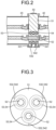
- FIG. 2 is a cross-sectional view of the instrument transformer of the gas-insulated switchgear according to the first embodiment.
- the instrument transformer 50 includes an insulation spacer 51, main circuit conductors 52, transformers 53, and current transformers 54.
- FIG. 3 is a front view of the insulation spacer of the gas-insulated switchgear according to the first embodiment.
- the main circuit conductors 52, the transformers 53, and the current transformers 54 are embedded in the insulation spacer 51.
- the instrument transformer 50 according to the first embodiment includes three of the main circuit conductors 52, three of the transformers 53, and three of the current transformers 54 to conduct three-phase currents having phases different from each other.
- the transformers 53 and the current transformers 54 each have a ring shape, and are embedded in the insulation spacer 51 to cause the center of each thereof to be positioned on the central axis of a corresponding one of the main circuit conductors 52.
- the transformers 53 and the current transformers 54 each include a corresponding one of secondary terminals 531 and 541, which are connected to corresponding ones of conductors 532 and 542 drawn from an outer circumferential portion of the insulation spacer 51.
- the transformers 53 and the current transformers 54 are supported from the outer circumference side of the insulation spacer 51 by support members so as to be coaxial with the main circuit conductors 52, the main circuit conductors 52, the transformers 53, and the current transformers 54 are integrally cast with the insulation spacer 51 by filling the mold with an insulating material.
- the transformers 53 and the current transformers 54 are embedded in the insulation spacer 51. Therefore, a member for supporting each of the transformers 53 and the current transformers 54 is unnecessary. This enables the gas-insulated switchgear 100 according to the first embodiment to reduce installation spaces for the insulation spacer 51, the current transformers 54, and the transformers 53.
- the gas-insulated switchgear 100 includes the ground potential plates 55 placed adjacent to the respective transformers 53, thereby making each of the transformers 53 less susceptible to induction from another one of the transformers 53 of a different phase. This can improve accuracy of detection of an anomalous voltage.
Landscapes
- Engineering & Computer Science (AREA)
- Power Engineering (AREA)
- Gas-Insulated Switchgears (AREA)
Abstract
Description
- The present disclosure relates to a gas-insulated device that encloses electrical insulation (hereinafter referred to simply as insulation) gas in a grounded metal tank.
- Some types of gas-insulated devices that enclose insulation gas in a grounded metal tank include an instrument transformer that includes, in combination, a current transformer for detecting an anomalous current and a transformer for detecting an anomalous voltage. In such instrument transformer, an insulation spacer that divides the inside of the tank into multiple zones each filled with gas, the current transformer for detecting an anomalous current, and the transformer for detecting an anomalous anomaly are installed separately.
- Separate installation of the insulation spacer, the current transformer, and the transformer requires not only three installation spaces for these components, but also requires spaces for installing members for supporting the current transformer and the transformer. Accordingly, separate installation of the insulation spacer, the current transformer, and the transformer hinders size reduction of the instrument transformer.
- Patent Literature 1 discloses an instrument transformer in which the current transformer for detecting an anomalous current is embedded in the insulation spacer. Use of the instrument transformer disclosed in Patent Literature 1 eliminates the need for the space for installation of the member for supporting the instrument current transformer, thereby enabling size reduction of a gas-insulated device as compared to when the insulation spacer and the current transformer for detecting an anomalous current are installed separately.
- Patent Literature 1:
Japanese Patent Application Laid-open No. H06-276629 - However, the instrument transformer disclosed in Patent Literature 1 does not disclose a method for supporting the transformer for detecting an anomalous voltage. That is, the instrument transformer disclosed in Patent Literature 1 needs to keep a space for installation of a member for supporting the transformer for detecting an anomalous voltage. Thus, the instrument transformer disclosed in Patent Literature 1 needs to further reduce the installation spaces for the current transformer for detecting an anomalous current and for the transformer for detecting an anomalous voltage.
- The present disclosure has been made in view of the foregoing, and it is an object of the present disclosure to provide a gas-insulated device including an instrument transformer having reduced installation spaces for the current transformer for detecting an anomalous current and for the transformer for detecting an anomalous voltage.
- To solve the problem and achieve the object described above, a gas-insulated device according to the present disclosure includes: a grounded tank divided into multiple zones each filled with gas; and an instrument transformer including, in combination, a current transformer for detecting an anomalous current and a transformer for detecting an anomalous voltage. The instrument transformer includes: an insulation spacer that forms the zones; and a main circuit conductor that penetrates through the insulation spacer. The current transformer has an annular shape, and the transformer has a shape forming at least part of an annular shape. The current transformer and the transformer are embedded in the insulation spacer to cause a center of the current transformer and a center of the transformer to be positioned on a central axis of the main circuit conductor.
- The present disclosure provides an advantage in that a gas-insulated device can be provided that includes an instrument transformer having reduced installation spaces for the current transformer for detecting an anomalous current and for the transformer for detecting an anomalous voltage.
-
-
FIG. 1 is a diagram illustrating a configuration of a gas-insulated switchgear according to a first embodiment. -
FIG. 2 is a cross-sectional view of an instrument transformer of the gas-insulated switchgear according to the first embodiment. -
FIG. 3 is a front view of an insulation spacer of the gas-insulated switchgear according to the first embodiment. -
FIG. 4 is a cross-sectional view of the instrument transformer of the gas-insulated switchgear according to a second embodiment. -
FIG. 5 is a front view of the insulation spacer of the gas-insulated switchgear according to the second embodiment. -
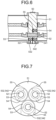
FIG. 6 is a cross-sectional view of the instrument transformer of the gas-insulated switchgear according to a third embodiment. -
FIG. 7 is a front view of the insulation spacer of the gas-insulated switchgear according to the third embodiment. -
FIG. 8 is a cross-sectional view of the instrument transformer of the gas-insulated switchgear according to a fourth embodiment. - A gas-insulated device according to embodiments will be described in detail below with reference to the drawings.
-
FIG. 1 is a diagram illustrating a configuration of a gas-insulated switchgear according to a first embodiment. A gas-insulatedswitchgear 100, which is one type of gas-insulated device, includes: acircuit breaker 20; groundedswitchgears disconnectors instrument transformer 50; abusbar 70; and abushing 80. Thebusbar 70 and thedisconnector 41 are connected to each other using connectingbusbars bushing 80 and thedisconnector 42 are connected to each other using a connectingbusbar 93. Each of thecircuit breaker 20, thegrounded switchgears disconnectors busbar 70, thebushing 80, and the connectingbusbars circuit breaker 20, thegrounded switchgears disconnectors busbar 70, thebushing 80, and the connectingbusbars -
FIG. 2 is a cross-sectional view of the instrument transformer of the gas-insulated switchgear according to the first embodiment. Theinstrument transformer 50 includes aninsulation spacer 51,main circuit conductors 52,transformers 53, andcurrent transformers 54.FIG. 3 is a front view of the insulation spacer of the gas-insulated switchgear according to the first embodiment. Themain circuit conductors 52, thetransformers 53, and thecurrent transformers 54 are embedded in theinsulation spacer 51. The instrument transformer 50 according to the first embodiment includes three of themain circuit conductors 52, three of thetransformers 53, and three of thecurrent transformers 54 to conduct three-phase currents having phases different from each other. Thetransformers 53 and thecurrent transformers 54 each have a ring shape, and are embedded in theinsulation spacer 51 to cause the center of each thereof to be positioned on the central axis of a corresponding one of themain circuit conductors 52. Thetransformers 53 and thecurrent transformers 54 each include a corresponding one ofsecondary terminals conductors insulation spacer 51. - The
main circuit conductors 52, thetransformers 53, and thecurrent transformers 54 are cast integrally with theinsulation spacer 51. Thetransformers 53 and thecurrent transformers 54 are supported from the outer circumference side of theinsulation spacer 51 by support members so as to be coaxial with themain circuit conductors 52 in the mold for casting theinsulation spacer 51. In the mold for casting theinsulation spacer 51, the support member that supports each of thetransformers 53 and thecurrent transformers 54 may be a corresponding one of theconductors secondary terminals transformers 53 and of thecurrent transformers 54. In a state thetransformers 53 and thecurrent transformers 54 are supported from the outer circumference side of theinsulation spacer 51 by support members so as to be coaxial with themain circuit conductors 52, themain circuit conductors 52, thetransformers 53, and thecurrent transformers 54 are integrally cast with theinsulation spacer 51 by filling the mold with an insulating material. - In the gas-insulated
switchgear 100 according to the first embodiment, thetransformers 53 and thecurrent transformers 54 are embedded in theinsulation spacer 51. Therefore, a member for supporting each of thetransformers 53 and thecurrent transformers 54 is unnecessary. This enables the gas-insulatedswitchgear 100 according to the first embodiment to reduce installation spaces for theinsulation spacer 51, thecurrent transformers 54, and thetransformers 53. - In addition, in the gas-insulated
switchgear 100 according to the first embodiment, there is no need to enclose insulation gas in theinstrument transformer 50, thus size reduction is achieved and the amount of use of insulation gas is reduced. - Moreover, in the gas-insulated
switchgear 100 according to the first embodiment, thetransformers 53 and thecurrent transformers 54 are embedded in theinsulation spacer 51 in theinstrument transformer 50, therefore a work of installation of thetransformers 53 and thecurrent transformers 54 to be coaxial with themain circuit conductors 52 during assembly of the gas-insulatedswitchgear 100 is unnecessary. Thus, the gas-insulatedswitchgear 100 according to the first embodiment enables a reduction in the number of steps in assembly work and an improvement in workability. -
FIG. 4 is a cross-sectional view of the instrument transformer of the gas-insulated switchgear according to a second embodiment.FIG. 5 is a front view of the insulation spacer of the gas-insulated switchgear according to the second embodiment. The gas-insulatedswitchgear 100 according to the second embodiment differs from the gas-insulatedswitchgear 100 according to the first embodiment in that groundpotential plates 55 are embedded in theinsulation spacer 51 of theinstrument transformer 50. The groundpotential plates 55 are each placed between a corresponding pair of thetransformers 53 and thecurrent transformers 54, and are bent at positions nearer to the center of theinsulation spacer 51 to cover thetransformers 53. - The gas-insulated
switchgear 100 according to the second embodiment includes the groundpotential plates 55 placed adjacent to therespective transformers 53, thereby making each of thetransformers 53 less susceptible to induction from another one of thetransformers 53 of a different phase. This can improve accuracy of detection of an anomalous voltage. -
FIG. 6 is a cross-sectional view of the instrument transformer of the gas-insulated switchgear according to a third embodiment.FIG. 7 is a front view of the insulation spacer of the gas-insulated switchgear according to the third embodiment. The gas-insulatedswitchgear 100 according to the third embodiment differs from the gas-insulatedswitchgear 100 according to the second embodiment in that thetransformers 53 of theinstrument transformer 50 each have an incomplete ring shape. In addition, the gas-insulatedswitchgear 100 according to the third embodiment is configured in which the groundpotential plates 55 are placed only in portions between thetransformers 53 and thecurrent transformers 54, and the groundpotential plates 55 do not cover therespective transformers 53 along the radial direction of themain circuit conductors 52. - The gas-insulated
switchgear 100 according to the third embodiment includes thetransformers 53 each having an incomplete ring shape. This enables thetransformers 53 to be installed coaxially with themain circuit conductors 52, from a position in the radial direction of themain circuit conductors 52. This can facilitate the work of installation of thetransformers 53 to be coaxial with themain circuit conductors 52 in the mold for casting theinsulation spacer 51. -
FIG. 8 is a cross-sectional view of the instrument transformer of the gas-insulated switchgear according to a fourth embodiment. The gas-insulatedswitchgear 100 according to the fourth embodiment differs from the gas-insulatedswitchgear 100 according to the first embodiment in that thetransformers 53 and thecurrent transformers 54 of theinstrument transformer 50 are joined to each other in pairs by insulatingsupport members 56, which have been cast integrally with theinsulation spacer 51. - In the mold for casting the
insulation spacer 51, thecurrent transformers 54 are supported from the outer circumference side by support members so as to be placed coaxially with themain circuit conductors 52. In the mold for casting theinsulation spacer 51, the support members that support thecurrent transformers 54 may be theconductors 542 connected to the secondary terminals of the respectivecurrent transformers 54. In addition, thetransformers 53 are fixed to thecurrent transformers 54 by the insulatingsupport members 56 to be thereby placed coaxially with themain circuit conductors 52. - The
instrument transformer 50 of the gas-insulatedswitchgear 100 according to the fourth embodiment enables thetransformers 53 to be placed coaxially with themain circuit conductors 52 by placing thecurrent transformers 54 coaxially with themain circuit conductors 52, provided that thetransformers 53 are previously fixed to thecurrent transformers 54 using the insulatingsupport members 56 to cause the centers of thetransformers 53 and the centers of respective corresponding ones of thecurrent transformers 54 to be positioned coaxially with each other. This can simplify the work of producing the gas-insulatedswitchgear 100 and improve production efficiency. - The configurations described in the foregoing embodiments are merely examples of aspects. These configurations may be combined with another known technology, and part of such configurations may be omitted and/or modified without departing from the spirit.
- 20 circuit breaker; 31, 32 grounded switchgear; 41, 42 disconnector; 50 instrument transformer; 51 insulation spacer; 52 main circuit conductor; 53 transformer; 54 current transformer; 55 ground potential plate; 56 insulating support member; 70 busbar; 80 bushing; 91, 92, 93 connecting busbar; 100 gas-insulated switchgear; 531, 541 secondary terminal; 532, 542 conductor.
Claims (4)
- A gas-insulated device comprising:a grounded tank divided into a plurality of zones each filled with gas; andan instrument transformer including, in combination, a current transformer for detecting an anomalous current and a transformer for detecting an anomalous voltage, whereinthe instrument transformer includes:an insulation spacer adapted to form the zones; anda main circuit conductor adapted to penetrate through the insulation spacer, whereinthe current transformer has an annular shape,the transformer has a shape forming at least part of an annular shape, andthe current transformer and the transformer are embedded in the insulation spacer to cause a center of the current transformer and a center of the transformer to be positioned on a central axis of the main circuit conductor.
- The gas-insulated device according to claim 1, wherein the instrument transformer includes:the main circuit conductor;the current transformer; andthe transformer correspondingly to each of a plurality of currents having phases different from each other.
- The gas-insulated device according to claim 2, wherein
a ground potential plate is embedded in the insulation spacer, adjacent to the transformer, the ground potential plate is adapted to suppress an induced current that would be caused to occur in the transformer placed adjacent to the ground potential plate by the transformer having another phase. - The gas-insulated device according to claim 1 or 2, wherein
an insulating support member adapted to fix the current transformer and the transformer is embedded in the insulation spacer.
Applications Claiming Priority (1)
| Application Number | Priority Date | Filing Date | Title |
|---|---|---|---|
| PCT/JP2022/033024 WO2024047851A1 (en) | 2022-09-01 | 2022-09-01 | Gas insulated apparatus |
Publications (2)
| Publication Number | Publication Date |
|---|---|
| EP4583335A1 true EP4583335A1 (en) | 2025-07-09 |
| EP4583335A4 EP4583335A4 (en) | 2025-09-24 |
Family
ID=85226224
Family Applications (1)
| Application Number | Title | Priority Date | Filing Date |
|---|---|---|---|
| EP22957445.4A Pending EP4583335A4 (en) | 2022-09-01 | 2022-09-01 | GAS-INSULATED DEVICE |
Country Status (3)
| Country | Link |
|---|---|
| EP (1) | EP4583335A4 (en) |
| JP (1) | JP7224567B1 (en) |
| WO (1) | WO2024047851A1 (en) |
Family Cites Families (8)
| Publication number | Priority date | Publication date | Assignee | Title |
|---|---|---|---|---|
| JPS4933062Y1 (en) * | 1969-06-28 | 1974-09-06 | ||
| DE2325442C2 (en) * | 1973-05-17 | 1982-03-04 | Siemens AG, 1000 Berlin und 8000 München | Transducer assembly |
| JPS50131507U (en) * | 1974-04-15 | 1975-10-29 | ||
| JPS6055214U (en) * | 1983-09-22 | 1985-04-18 | 富士電機株式会社 | Internal accident detection device for gas insulated equipment |
| JPS61415U (en) * | 1984-06-05 | 1986-01-06 | 株式会社明電舎 | Connecting pipe section of gas insulated reduced type switchgear |
| JPH06276629A (en) | 1993-03-17 | 1994-09-30 | Toshiba Corp | Insulation spacer with transformer for instrument |
| JP2970375B2 (en) * | 1993-12-27 | 1999-11-02 | 株式会社高岳製作所 | Optical voltage measuring device |
| JP4728797B2 (en) * | 2005-12-19 | 2011-07-20 | 財団法人電力中央研究所 | Gas insulated power equipment |
-
2022
- 2022-09-01 JP JP2022574622A patent/JP7224567B1/en active Active
- 2022-09-01 WO PCT/JP2022/033024 patent/WO2024047851A1/en not_active Ceased
- 2022-09-01 EP EP22957445.4A patent/EP4583335A4/en active Pending
Also Published As
| Publication number | Publication date |
|---|---|
| WO2024047851A1 (en) | 2024-03-07 |
| EP4583335A4 (en) | 2025-09-24 |
| JPWO2024047851A1 (en) | 2024-03-07 |
| JP7224567B1 (en) | 2023-02-17 |
Similar Documents
| Publication | Publication Date | Title |
|---|---|---|
| US5578805A (en) | Metal-enclosed gas-filled switchgear units | |
| CN100521418C (en) | Gas insulated switch gear | |
| JPH0770276B2 (en) | Gas circuit breaker | |
| US5578804A (en) | Metal-enclosed gas-insulated switching installation | |
| US20070119818A1 (en) | Compressed-gas-insulated switch-disconnector module and bushing configuration | |
| US3643003A (en) | Transformer termination for metal-enclosed, compressed-gas-insulated electrical conductors | |
| HU189964B (en) | Metal-clad gas-insulation switching apparatus | |
| EP4583335A1 (en) | Gas insulated apparatus | |
| US10038312B2 (en) | High-voltage combined electrical apparatus | |
| CN101507069A (en) | Connection module with an encapsulating housing | |
| KR20090106391A (en) | High voltage switchgear | |
| JP4490486B2 (en) | High voltage switchgear assembly | |
| KR20030076180A (en) | Gas insulation switch | |
| JP3208660B2 (en) | Gas insulated switchgear | |
| US3129310A (en) | Potential-tap assembly for relatively high-voltage equipment | |
| US3927246A (en) | Three-phase cable termination for metal enclosed compressed gas-insulated substation | |
| JP2000350318A (en) | Gas insulated ground switch | |
| JPH0622420A (en) | Switchgear | |
| KR20110134409A (en) | 3-phase batch gas insulated switchgear | |
| US11626244B2 (en) | Assembly for connecting to a high-voltage grid | |
| EP3540882B1 (en) | Compact circuit breaker for a gas insulated switchgear | |
| JPH1056709A (en) | Cubicle gas insulation switchgear | |
| CN106129824B (en) | A kind of direct connection device of three-phase combined type GIS busbares and transformer | |
| JP2000308222A (en) | Main circuit switchgear | |
| JP2002186126A (en) | Main circuit switchgear |
Legal Events
| Date | Code | Title | Description |
|---|---|---|---|
| STAA | Information on the status of an ep patent application or granted ep patent |
Free format text: STATUS: THE INTERNATIONAL PUBLICATION HAS BEEN MADE |
|
| PUAI | Public reference made under article 153(3) epc to a published international application that has entered the european phase |
Free format text: ORIGINAL CODE: 0009012 |
|
| STAA | Information on the status of an ep patent application or granted ep patent |
Free format text: STATUS: REQUEST FOR EXAMINATION WAS MADE |
|
| 17P | Request for examination filed |
Effective date: 20241206 |
|
| AK | Designated contracting states |
Kind code of ref document: A1 Designated state(s): AL AT BE BG CH CY CZ DE DK EE ES FI FR GB GR HR HU IE IS IT LI LT LU LV MC MK MT NL NO PL PT RO RS SE SI SK SM TR |
|
| A4 | Supplementary search report drawn up and despatched |
Effective date: 20250822 |
|
| RIC1 | Information provided on ipc code assigned before grant |
Ipc: H02B 13/035 20060101AFI20250818BHEP Ipc: H02G 5/06 20060101ALN20250818BHEP |
|
| DAV | Request for validation of the european patent (deleted) | ||
| DAX | Request for extension of the european patent (deleted) |