EP4583323A1 - Connector assembly and method of assembling a connector assembly - Google Patents
Connector assembly and method of assembling a connector assembly Download PDFInfo
- Publication number
- EP4583323A1 EP4583323A1 EP25150228.2A EP25150228A EP4583323A1 EP 4583323 A1 EP4583323 A1 EP 4583323A1 EP 25150228 A EP25150228 A EP 25150228A EP 4583323 A1 EP4583323 A1 EP 4583323A1
- Authority
- EP
- European Patent Office
- Prior art keywords
- housing part
- wedge
- terminal holder
- connector
- wedge portion
- Prior art date
- Legal status (The legal status is an assumption and is not a legal conclusion. Google has not performed a legal analysis and makes no representation as to the accuracy of the status listed.)
- Pending
Links
Images


Classifications
-
- H—ELECTRICITY
- H01—ELECTRIC ELEMENTS
- H01R—ELECTRICALLY-CONDUCTIVE CONNECTIONS; STRUCTURAL ASSOCIATIONS OF A PLURALITY OF MUTUALLY-INSULATED ELECTRICAL CONNECTING ELEMENTS; COUPLING DEVICES; CURRENT COLLECTORS
- H01R13/00—Details of coupling devices of the kinds covered by groups H01R12/70 or H01R24/00 - H01R33/00
- H01R13/46—Bases; Cases
- H01R13/502—Bases; Cases composed of different pieces
- H01R13/506—Bases; Cases composed of different pieces assembled by snap action of the parts
-
- H—ELECTRICITY
- H01—ELECTRIC ELEMENTS
- H01R—ELECTRICALLY-CONDUCTIVE CONNECTIONS; STRUCTURAL ASSOCIATIONS OF A PLURALITY OF MUTUALLY-INSULATED ELECTRICAL CONNECTING ELEMENTS; COUPLING DEVICES; CURRENT COLLECTORS
- H01R13/00—Details of coupling devices of the kinds covered by groups H01R12/70 or H01R24/00 - H01R33/00
- H01R13/40—Securing contact members in or to a base or case; Insulating of contact members
-
- H—ELECTRICITY
- H01—ELECTRIC ELEMENTS
- H01R—ELECTRICALLY-CONDUCTIVE CONNECTIONS; STRUCTURAL ASSOCIATIONS OF A PLURALITY OF MUTUALLY-INSULATED ELECTRICAL CONNECTING ELEMENTS; COUPLING DEVICES; CURRENT COLLECTORS
- H01R13/00—Details of coupling devices of the kinds covered by groups H01R12/70 or H01R24/00 - H01R33/00
- H01R13/02—Contact members
-
- H—ELECTRICITY
- H01—ELECTRIC ELEMENTS
- H01R—ELECTRICALLY-CONDUCTIVE CONNECTIONS; STRUCTURAL ASSOCIATIONS OF A PLURALITY OF MUTUALLY-INSULATED ELECTRICAL CONNECTING ELEMENTS; COUPLING DEVICES; CURRENT COLLECTORS
- H01R13/00—Details of coupling devices of the kinds covered by groups H01R12/70 or H01R24/00 - H01R33/00
- H01R13/40—Securing contact members in or to a base or case; Insulating of contact members
- H01R13/42—Securing in a demountable manner
- H01R13/436—Securing a plurality of contact members by one locking piece or operation
-
- H—ELECTRICITY
- H01—ELECTRIC ELEMENTS
- H01R—ELECTRICALLY-CONDUCTIVE CONNECTIONS; STRUCTURAL ASSOCIATIONS OF A PLURALITY OF MUTUALLY-INSULATED ELECTRICAL CONNECTING ELEMENTS; COUPLING DEVICES; CURRENT COLLECTORS
- H01R13/00—Details of coupling devices of the kinds covered by groups H01R12/70 or H01R24/00 - H01R33/00
- H01R13/46—Bases; Cases
- H01R13/502—Bases; Cases composed of different pieces
-
- H—ELECTRICITY
- H01—ELECTRIC ELEMENTS
- H01R—ELECTRICALLY-CONDUCTIVE CONNECTIONS; STRUCTURAL ASSOCIATIONS OF A PLURALITY OF MUTUALLY-INSULATED ELECTRICAL CONNECTING ELEMENTS; COUPLING DEVICES; CURRENT COLLECTORS
- H01R43/00—Apparatus or processes specially adapted for manufacturing, assembling, maintaining, or repairing of line connectors or current collectors or for joining electric conductors
- H01R43/18—Apparatus or processes specially adapted for manufacturing, assembling, maintaining, or repairing of line connectors or current collectors or for joining electric conductors for manufacturing bases or cases for contact members
-
- H—ELECTRICITY
- H01—ELECTRIC ELEMENTS
- H01R—ELECTRICALLY-CONDUCTIVE CONNECTIONS; STRUCTURAL ASSOCIATIONS OF A PLURALITY OF MUTUALLY-INSULATED ELECTRICAL CONNECTING ELEMENTS; COUPLING DEVICES; CURRENT COLLECTORS
- H01R43/00—Apparatus or processes specially adapted for manufacturing, assembling, maintaining, or repairing of line connectors or current collectors or for joining electric conductors
- H01R43/20—Apparatus or processes specially adapted for manufacturing, assembling, maintaining, or repairing of line connectors or current collectors or for joining electric conductors for assembling or disassembling contact members with insulating base, case or sleeve
-
- H—ELECTRICITY
- H01—ELECTRIC ELEMENTS
- H01R—ELECTRICALLY-CONDUCTIVE CONNECTIONS; STRUCTURAL ASSOCIATIONS OF A PLURALITY OF MUTUALLY-INSULATED ELECTRICAL CONNECTING ELEMENTS; COUPLING DEVICES; CURRENT COLLECTORS
- H01R43/00—Apparatus or processes specially adapted for manufacturing, assembling, maintaining, or repairing of line connectors or current collectors or for joining electric conductors
- H01R43/26—Apparatus or processes specially adapted for manufacturing, assembling, maintaining, or repairing of line connectors or current collectors or for joining electric conductors for engaging or disengaging the two parts of a coupling device
-
- H—ELECTRICITY
- H01—ELECTRIC ELEMENTS
- H01R—ELECTRICALLY-CONDUCTIVE CONNECTIONS; STRUCTURAL ASSOCIATIONS OF A PLURALITY OF MUTUALLY-INSULATED ELECTRICAL CONNECTING ELEMENTS; COUPLING DEVICES; CURRENT COLLECTORS
- H01R13/00—Details of coupling devices of the kinds covered by groups H01R12/70 or H01R24/00 - H01R33/00
- H01R13/66—Structural association with built-in electrical component
- H01R13/665—Structural association with built-in electrical component with built-in electronic circuit
- H01R13/6658—Structural association with built-in electrical component with built-in electronic circuit on printed circuit board
-
- H—ELECTRICITY
- H01—ELECTRIC ELEMENTS
- H01R—ELECTRICALLY-CONDUCTIVE CONNECTIONS; STRUCTURAL ASSOCIATIONS OF A PLURALITY OF MUTUALLY-INSULATED ELECTRICAL CONNECTING ELEMENTS; COUPLING DEVICES; CURRENT COLLECTORS
- H01R2201/00—Connectors or connections adapted for particular applications
- H01R2201/26—Connectors or connections adapted for particular applications for vehicles
Definitions
- the following describes a connector assembly and method of assembly for use in fastening together parts of automotive connectors.
- Certain types of connector assembly can accommodate electrical terminals which are electrically connected to a printed circuit board.
- the assembly of the terminals on the printed circuit board, the assembly of the printed circuit with its terminals on a terminal holder and the assembly of the whole connector are operations that can be carried out on separate assembly lines, or even by different suppliers.
- These various assemblies can generate constraints that make it necessary to avoid rigid fixing of parts of the connector. For example, it may be advantageous to clamp a terminal holder between two die-cast housing parts. As a result, the terminals of the assembled connector may not overlap as well with the contacts of a counter-connector. A solution is therefore needed to solve this problem.
- the following disclosure relates to a connector comprising a PCB carrier or holder, but is not limited to such a configuration.
- Terminals can be mounted on a terminal holder and connected to conductive elements (wires, busbars, etc.) without the need for a PCB.
- a problem of relative movement between a terminal holder and a housing part may arise.
- Such a relative movement can be, in particular, detrimental to the quality and reliability of the electrical contact between the terminals of a connector and of a counter-connector configured to be mated to the connector.
- the total load resulting from the mating sequence female connector with male connector
- a connector assembly and an assembly method that at least partially meet the requirements of modern assembly processes are disclosed below.
- the present disclosure relates to a connector assembly comprising a connector.
- the connector is intended to be mated and electrically connected to a counterpart connector.
- the connector is a male connector and the counterpart connector is a female connector (but it can also be the other way round).
- this male connector is a header.
- the connector comprises a first housing part, a second housing part and a terminal holder accommodated in the first housing part. At least one terminal is accommodated in the terminal holder. Said at least one terminal has a contact portion configured to be connected to a terminal accommodated in the counterpart connector. For example, said contact portion extends essentially in a mating direction of the connector with the counterpart connector.
- the second housing part is configured to be mounted with the first housing part with at least one mounting displacement of the second housing part relative to the first housing part, parallel to the mating direction.
- the second housing part is mounted with the first housing part with a displacement relative to each other, this displacement having at least one component parallel to the mating direction.
- the second housing part comprises an actuating portion and the terminal holder comprises a wedge portion, the wedge portion being configured to be at least partially inserted between the first housing part and the terminal holder.
- the actuating portion is configured to press on the wedge portion when the second housing part is mounted with the first housing part, along the mounting displacement.
- the terminal holder and the wedge portion are configured to block a movement parallel to the mating direction between the first housing part and the terminal holder when the wedge portion is pushed by the actuating portion.
- the actuating portion has a beam-like shape extending longitudinally parallel to the mating direction.
- Such an actuating portion has therefore a simple shape, which is easy to mould, and which can be robust.
- the terminal holder comprises a base portion and a flexible leg linked to the base portion by a hinge at one end and comprises the wedge portion at another end, and wherein the flexible leg comprises a ramp configured so that that the actuating portion interacts with the ramp and the flexible leg rotates about the hinge when the second housing part is mounted with the first housing part, along the mounting displacement.
- the flexible leg is thinner in the vicinity of the hinge than in the vicinity of the wedge portion.
- the wedge portion comprises at least one first wedge and at least one second wedge, both projecting at the free end of the flexible leg, in a direction essentially perpendicular to the mating direction.
- the actuating portion is engaged in a channel essentially parallel to the mating direction, and the first wedge projects at a mouth of the channel. With such a configuration, it is possible not to use sliders for moulding the terminal holder.
- the actuating portion and the wedge portion are configured so that the actuating portion pushes a first side of the wedge portion against the first housing part and a second side of the wedge portion against the terminal holder.
- the first wedge comprises a first friction surface having a convex shape.
- This locking function (in addition to the locking function provided by the interaction of second side of the wedge portion against the terminal holder) also ensures the correct position of the wedge between the first housing part, the second housing part and the terminal holder, even if the flexible leg is damaged or broken.
- the connector assembly is configured so that any movement in the mating direction of the terminal holder relative to the first housing part is controlled only by interaction of the actuating part with the wedge portion.
- the insertion direction is perpendicular to the mating direction.
- This disclosure relates to a connector assembly 100 (see Figure 8 ).
- This connector assembly 100 comprises at least a connector 10.
- the connector assembly 100 can also comprise a counter-connector (not illustrated).
- the connector 10 is then configured to mate with the counter-connector.
- the connector 10 is a male connector.
- this male connector 10 is a header.
- the connector 10 comprises at least a first housing part 1, a second housing part 2 and a terminal holder 3.
- the first housing part 1 is a die-cast housing.
- this die-cast housing is part of a power box.
- the second housing part 2 is a header shroud.
- the second housing part 2 is a moulded plastic part.
- the terminal holder 3 is also called pin block.
- the terminal holder 3 is made of a dielectric material.
- the terminal holder 3 is a moulded plastic part.
- At least one terminal 4 is accommodated in the terminal holder 3 (see Figure 1 ).
- the terminal holder 3 supports several terminals 4.
- Each terminal 4 maintained by the terminal holder 3 is made of an electrically conductive material.
- each one of these terminals 4 is made as a male terminal cut from a sheet of conductive material and bent so as to have a contact portion 5 configured to be connected to a female terminal accommodated in the counterpart connector. This contact portion 5 extends essentially in a mating direction MD of the connector 10 with the counterpart connector.
- each one of these terminals 4 is stitched in the terminal holder 3.
- the terminal holder 3 is overmoulded over at least one, or each one, of these terminals 4.
- at least one, or each one, of these terminals 4 is simply inserted in an opening 6 made in the terminal holder 3 (see Figure 4 ).
- each one of these terminals 4 extends between the contact portion 5 and a connecting portion 7 (see Figure 1 ).
- the connecting portion 7 is soldered to a PCB 8.
- the contact portion 5 extends essentially parallel to the mating direction MD. Therefore, when the male connector 10 is mated to a female counter-connector, it is essential that the insertion force between the male and female terminals is not transmitted, or not fully transmitted, at the solder joints on the PCB 8.
- the terminal holder 3 is mounted in the first housing part 1 with the terminals 4 and the PCB 8 (see Figures 1 and 2 ).
- the terminal holder 3 is mounted in the first housing part 1 in an insertion direction ID which is perpendicular to the mating direction MD.
- the terminal holder 3 comprises a base portion 9 and an insulating wall 11.
- the base portion 9 has essentially a plate-like shape extending perpendicular to the mating direction MD (when the terminal holder 3 is mounted in the first housing part 1).
- the openings 6 are made through the base portion 9.
- the wall 11 extends perpendicular to the base portion 9.
- the terminal holder 3 also comprises wedge means.
- the terminal holder 3 can comprise one or several wedge means (for example, at opposite corners or end sides of the base portion 9).
- each wedge means comprises at least one flexible leg 12.
- Each flexible leg 11 extends essentially parallel to the mating direction MD (when the terminal holder 3 is mounted in the first housing part 1), between a hinge 13 and a wedge portion 14.
- Each hinge 13 joins a flexible leg 12 to the base portion 9. More particularly, each flexible leg 12 extends from a respective hinge 13, in a direction opposite to the wall 11.
- each flexible leg 12 extends from a first side of the base portion 9 from which the wall 11 extends, to a second side of the base portion 9, opposite the first side, the wedge portion 14 projecting at least partially on the second side.
- the length of the flexible leg 12 is longer that the thickness of the base portion 9.
- Each flexible leg 12 comprises a slanted ramp 15 configured so that the flexible leg 12, seen in cross section in a plane perpendicular to the wall and parallel to the mating direction MD (see Figure 5 ), is thinner in the vicinity of the hinge 13 than in the vicinity of the wedge portion 14.
- the terminal holder 3 comprises a guiding wall 16 facing the ramp 15.
- the distance between the flexible leg 12 and the guiding wall 16 in line with the hinge 13 (in a direction perpendicular to the mating direction MD) is larger than towards the wedge portion 14.
- the guiding wall 16 extends in a plane parallel to mating direction MD, while the ramp 15 makes an angle with the mating direction MD.
- the wedge portion 14 comprises at least one first wedge 17 and at least one second wedges 18.
- the wedge portion 14 comprises one first wedge 17 and two second wedges 18 (see Figure 5 ).
- the first wedge 17 also comprises a first friction surface 21.
- the first friction surface 21 has a convex shape with a curvature directed essentially in the direction of the channel 19.
- Each second wedge 18 extends in a gap 28 located between the terminal holder 3 and the first housing part 1.
- the terminal holder 3 comprises a slanted surface 22.
- the slanted surface 22 is offset, in a plane perpendicular to the mating direction MD, from the second wedge 18 (see Figure 6 ).
- the second wedge 18 comes below the slanted surface 22, in the gap 28 between the slanted surface 22 and the first housing part 1 (see Figure 7 ).
- Each second wedge 18 comprises a second friction surface 23.
- This second friction surface 23 forms an angle of greater or equal to 90° with the longitudinal direction of the flexible leg 12.
- the flexible leg 12 can be flexed up to a position in which the friction surface 23 is pushed against the slanted surface 22.
- Each second wedge 18 also comprises a bottom surface 24 directed towards the first housing part 1.
- the second housing part 2 comprises at least one actuating portion 25 (see Figs. 6 and 7 ).
- the second housing part 2 comprises as many actuating portions 25 as there are wedge means.
- the actuating portion 25 has a beam shape extending longitudinally parallel to the mating direction MD.
- the shape of each actuating portion 25 is adapted to penetrate and slide into a respective channel 19.
- the thickness of the actuating portion 25 is greater than the smallest dimension of the channel 19 in a direction perpendicular to the guiding wall 16 (with reference to Figures 6 and 7 ).
- the assembly process of the connector assembly 100 comprises, for example, at least the following steps:
- the movement, in the mating direction MD, of the terminal holder 3 relative to the first housing part 1 is cancelled.
- the gap 28 between the terminal holder 3 and the first housing part 1 is compensated.
- Any movement in the mating direction MD of the terminal holder 3 relative to the first housing part 1 is controlled only by interaction of the actuating part 25 with the wedge portion 14, i.e. such movement is not controlled by a screwing means, latching means or the like.
- the movement, in the mating direction MD, of the second housing part 2 relative to the terminal holder 3 and the first housing part 1 is cancelled too.
- first housing part 1 being a die-cast housing and the second housing part 2 being a header shroud
- the invention can be used in other kinds of connector assemblies in which a gap needs to be compensated.
- the connector assembly above-disclosed has the advantage that it increases the contact overlap between the respective terminals of the connector 10 and the counter-connector.
- the invention has also the advantage of decreasing or cancelling the relative movement between the terminal holder 3 and the PCB 8 (this preserves the solder joints between terminals and the PCB).
Landscapes
- Engineering & Computer Science (AREA)
- Manufacturing & Machinery (AREA)
- Connector Housings Or Holding Contact Members (AREA)
Abstract
A connector assembly comprising a connector comprising a first housing part (1), a second housing part and a terminal holder (3) accommodated in the first housing part (1). The second housing part comprises an actuating portion (25) and the terminal holder (3) comprises a wedge portion (14), the wedge portion (14) being configured to be at least partially inserted between the first housing part (1) and the terminal holder (3). The actuating portion (25) is configured to press on the wedge portion (14) when the second housing part is mounted with the first housing part (1). The terminal holder (3) and the wedge portion (14) are configured to block a movement parallel to the mating direction (MD) between the first housing part (1) and the terminal holder (3) when the wedge portion (14) is pushed by the actuating portion (25).
Description
- The following describes a connector assembly and method of assembly for use in fastening together parts of automotive connectors.
- Certain types of connector assembly can accommodate electrical terminals which are electrically connected to a printed circuit board. In this case, the assembly of the terminals on the printed circuit board, the assembly of the printed circuit with its terminals on a terminal holder and the assembly of the whole connector are operations that can be carried out on separate assembly lines, or even by different suppliers. These various assemblies can generate constraints that make it necessary to avoid rigid fixing of parts of the connector. For example, it may be advantageous to clamp a terminal holder between two die-cast housing parts. As a result, the terminals of the assembled connector may not overlap as well with the contacts of a counter-connector. A solution is therefore needed to solve this problem.
- The following disclosure relates to a connector comprising a PCB carrier or holder, but is not limited to such a configuration. Terminals can be mounted on a terminal holder and connected to conductive elements (wires, busbars, etc.) without the need for a PCB. Whatever the case may be, depending on the configuration of the connector assemblies, a problem of relative movement between a terminal holder and a housing part may arise. Such a relative movement can be, in particular, detrimental to the quality and reliability of the electrical contact between the terminals of a connector and of a counter-connector configured to be mated to the connector. In addition, the total load resulting from the mating sequence (female connector with male connector) is subject to the risk of being applied to the soldering area of the PCB terminals.
- A connector assembly and an assembly method that at least partially meet the requirements of modern assembly processes are disclosed below.
- The present disclosure relates to a connector assembly comprising a connector. The connector is intended to be mated and electrically connected to a counterpart connector. For example, the connector is a male connector and the counterpart connector is a female connector (but it can also be the other way round). For example, this male connector is a header. The connector comprises a first housing part, a second housing part and a terminal holder accommodated in the first housing part. At least one terminal is accommodated in the terminal holder. Said at least one terminal has a contact portion configured to be connected to a terminal accommodated in the counterpart connector. For example, said contact portion extends essentially in a mating direction of the connector with the counterpart connector. The second housing part is configured to be mounted with the first housing part with at least one mounting displacement of the second housing part relative to the first housing part, parallel to the mating direction. In other words, the second housing part is mounted with the first housing part with a displacement relative to each other, this displacement having at least one component parallel to the mating direction.
- Furthermore, the second housing part comprises an actuating portion and the terminal holder comprises a wedge portion, the wedge portion being configured to be at least partially inserted between the first housing part and the terminal holder. The actuating portion is configured to press on the wedge portion when the second housing part is mounted with the first housing part, along the mounting displacement. The terminal holder and the wedge portion are configured to block a movement parallel to the mating direction between the first housing part and the terminal holder when the wedge portion is pushed by the actuating portion.
- The features above have the advantages that:
- when it is not appropriate to use rigid fixation means (screwing means, locking means, etc.) to mount the terminal holder in the second housing part, before assembly with the first housing part, they enable the relative movement between the terminal holder and the second housing part to be cancelled (even in the case of unavoidable clearances due to the manufacturing tolerances);
- they enable cancelling the movement in the mating direction between the first housing part and the terminal holder and as a consequence the enable a more precise and reliable relative positioning of the connector and counter-connector terminals;
- they are easy to implement;
- they can be cost effective, as no sliders are required for their moulding;
- they can be implemented in various configurations and designs; etc.
- According to an embodiment, the actuating portion has a beam-like shape extending longitudinally parallel to the mating direction. Such an actuating portion has therefore a simple shape, which is easy to mould, and which can be robust.
- According to an embodiment, the terminal holder comprises a base portion and a flexible leg linked to the base portion by a hinge at one end and comprises the wedge portion at another end, and wherein the flexible leg comprises a ramp configured so that that the actuating portion interacts with the ramp and the flexible leg rotates about the hinge when the second housing part is mounted with the first housing part, along the mounting displacement. For example, the flexible leg is thinner in the vicinity of the hinge than in the vicinity of the wedge portion. For example, the wedge portion comprises at least one first wedge and at least one second wedge, both projecting at the free end of the flexible leg, in a direction essentially perpendicular to the mating direction. For example, the actuating portion is engaged in a channel essentially parallel to the mating direction, and the first wedge projects at a mouth of the channel. With such a configuration, it is possible not to use sliders for moulding the terminal holder.
- According to an embodiment, the actuating portion and the wedge portion are configured so that the actuating portion pushes a first side of the wedge portion against the first housing part and a second side of the wedge portion against the terminal holder.
- According to an embodiment, the first wedge comprises a first friction surface having a convex shape. Such a configuration enables a robust Wedge Friction Lock. This locking function (in addition to the locking function provided by the interaction of second side of the wedge portion against the terminal holder) also ensures the correct position of the wedge between the first housing part, the second housing part and the terminal holder, even if the flexible leg is damaged or broken.
- According to an embodiment, the connector assembly is configured so that any movement in the mating direction of the terminal holder relative to the first housing part is controlled only by interaction of the actuating part with the wedge portion.
- According to another aspect, it is disclosed below a method for assembling a connector comprising at least the following steps:
- mounting the terminal holder in the first housing part an insertion direction;
- mounting the second housing part with the first housing part;
- mounting the connector with a counter-connector parallel to a mating direction, thereby pushing the second housing part in the mating direction and pushing the actuating portion against the wedge portion so as to pivot the wedge portion to press a first side of the wedge portion against the first housing part and a second side of the wedge portion against the terminal holder.
- According to an embodiment, the insertion direction is perpendicular to the mating direction.
- Exemplary embodiments and functions of the present disclosure will be described in more detail in the following with reference to the drawings showing in:
-
Figs. 1 and 2 are schematic and exploded perspective views of an example of embodiment of a connector assembly; -
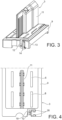
Fig. 3 is a perspective view of the terminal holder of the connector assembly shown inFigs. 1 and 2 ; -
Fig. 4 shows an elevation view of part of the terminal holder shown inFig. 3 ; -
Fig. 5 is a perspective view of the wedge portion of the terminal holder shown inFigs. 3 and 4 ; -
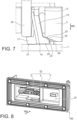
Fig. 6 and7 are lateral views of the wedge portion of the terminal holder shown inFigs. 3 and 4 , as well as portions of the first housing part and the second housing part, with which the wedge portion interacts; and -
Fig. 8 is a perspective view of the example of embodiment of a connector assembly shown inFigs. 1 and 2 , with the first housing part the second housing part and the terminal holder being assembled. - This disclosure relates to a connector assembly 100 (see
Figure 8 ). Thisconnector assembly 100 comprises at least aconnector 10. Theconnector assembly 100 can also comprise a counter-connector (not illustrated). Theconnector 10 is then configured to mate with the counter-connector. For example, theconnector 10 is a male connector. For example, thismale connector 10 is a header. Theconnector 10 comprises at least afirst housing part 1, asecond housing part 2 and aterminal holder 3. For example, thefirst housing part 1 is a die-cast housing. For example, this die-cast housing is part of a power box. For example, thesecond housing part 2 is a header shroud. For example, thesecond housing part 2 is a moulded plastic part. - The
terminal holder 3 is also called pin block. Theterminal holder 3 is made of a dielectric material. For example, theterminal holder 3 is a moulded plastic part. At least oneterminal 4 is accommodated in the terminal holder 3 (seeFigure 1 ). Possibly, theterminal holder 3 supportsseveral terminals 4. Eachterminal 4 maintained by theterminal holder 3 is made of an electrically conductive material. For example, each one of theseterminals 4 is made as a male terminal cut from a sheet of conductive material and bent so as to have acontact portion 5 configured to be connected to a female terminal accommodated in the counterpart connector. Thiscontact portion 5 extends essentially in a mating direction MD of theconnector 10 with the counterpart connector. For example, at least one, or each one, of theseterminals 4 is stitched in theterminal holder 3. Alternatively, theterminal holder 3 is overmoulded over at least one, or each one, of theseterminals 4. Alternatively, at least one, or each one, of theseterminals 4 is simply inserted in anopening 6 made in the terminal holder 3 (seeFigure 4 ). For example, each one of theseterminals 4 extends between thecontact portion 5 and a connecting portion 7 (seeFigure 1 ). For example, the connectingportion 7 is soldered to aPCB 8. Thecontact portion 5 extends essentially parallel to the mating direction MD. Therefore, when themale connector 10 is mated to a female counter-connector, it is essential that the insertion force between the male and female terminals is not transmitted, or not fully transmitted, at the solder joints on thePCB 8. - The
terminal holder 3 is mounted in thefirst housing part 1 with theterminals 4 and the PCB 8 (seeFigures 1 and 2 ). For example, theterminal holder 3 is mounted in thefirst housing part 1 in an insertion direction ID which is perpendicular to the mating direction MD. - As illustrated in
Figures 3 to 5 in particular, theterminal holder 3 comprises abase portion 9 and an insulatingwall 11. Thebase portion 9 has essentially a plate-like shape extending perpendicular to the mating direction MD (when theterminal holder 3 is mounted in the first housing part 1). Theopenings 6 are made through thebase portion 9. Thewall 11 extends perpendicular to thebase portion 9. - The
terminal holder 3 also comprises wedge means. Theterminal holder 3 can comprise one or several wedge means (for example, at opposite corners or end sides of the base portion 9). For example, each wedge means comprises at least oneflexible leg 12. Eachflexible leg 11 extends essentially parallel to the mating direction MD (when theterminal holder 3 is mounted in the first housing part 1), between ahinge 13 and awedge portion 14. Eachhinge 13 joins aflexible leg 12 to thebase portion 9. More particularly, eachflexible leg 12 extends from arespective hinge 13, in a direction opposite to thewall 11. In other words, eachflexible leg 12 extends from a first side of thebase portion 9 from which thewall 11 extends, to a second side of thebase portion 9, opposite the first side, thewedge portion 14 projecting at least partially on the second side. The length of theflexible leg 12 is longer that the thickness of thebase portion 9. - Each
flexible leg 12 comprises a slantedramp 15 configured so that theflexible leg 12, seen in cross section in a plane perpendicular to the wall and parallel to the mating direction MD (seeFigure 5 ), is thinner in the vicinity of thehinge 13 than in the vicinity of thewedge portion 14. Advantageously, theterminal holder 3 comprises a guidingwall 16 facing theramp 15. Advantageously, the distance between theflexible leg 12 and the guidingwall 16 in line with the hinge 13 (in a direction perpendicular to the mating direction MD) is larger than towards thewedge portion 14. For example, the guidingwall 16 extends in a plane parallel to mating direction MD, while theramp 15 makes an angle with the mating direction MD. - The
wedge portion 14 comprises at least onefirst wedge 17 and at least onesecond wedges 18. In the illustrated example, thewedge portion 14 comprises onefirst wedge 17 and two second wedges 18 (seeFigure 5 ). - The
first wedge 17 projects at the free end of theflexible leg 12, below theramp 15, in a direction opposite to thesecond wedges 18. In other words, thefirst wedge 17 projects in achannel 19, at the end of a channel or at the mouth of thechannel 19, at least partially delimited by theflexible leg 12 and the guidingwall 16. In the illustrated example, thefirst wedge 17 projects at the mouth of thechannel 19. Thefirst wedge 17 comprises a blockingsurface 20 facing an outlet of thechannel 19. In the illustrated example, the blockingsurface 20 at least partially closes the mouth of thechannel 19. The blockingsurface 20 forms an angle less than or equal to 90° with the longitudinal direction of theflexible leg 12 and more than 90° with the ramp 15 (seeFigure 6 ). When theflexible leg 12 is not flexed, the blockingsurface 20 forms an angle greater or equal to 90° with the guidingwall 16. When theflexible leg 12 is fully flexed, the blockingsurface 20 forms an angle less than or equal to 90° with the guiding wall 16 (seeFigure 7 ). Thefirst wedge 17 also comprises afirst friction surface 21. Advantageously, thefirst friction surface 21 has a convex shape with a curvature directed essentially in the direction of thechannel 19. - Each
second wedge 18 extends in agap 28 located between theterminal holder 3 and thefirst housing part 1. Theterminal holder 3 comprises a slantedsurface 22. When theflexible leg 12 is not flexed, the slantedsurface 22 is offset, in a plane perpendicular to the mating direction MD, from the second wedge 18 (seeFigure 6 ). When theflexible leg 12 is flexed, thesecond wedge 18 comes below the slantedsurface 22, in thegap 28 between theslanted surface 22 and the first housing part 1 (seeFigure 7 ). - Each
second wedge 18 comprises asecond friction surface 23. Thissecond friction surface 23 forms an angle of greater or equal to 90° with the longitudinal direction of theflexible leg 12. Theflexible leg 12 can be flexed up to a position in which thefriction surface 23 is pushed against the slantedsurface 22. Eachsecond wedge 18 also comprises abottom surface 24 directed towards thefirst housing part 1. - The
second housing part 2 comprises at least one actuating portion 25 (seeFigs. 6 and7 ). For example, thesecond housing part 2 comprises as many actuatingportions 25 as there are wedge means. In the illustrated example, the actuatingportion 25 has a beam shape extending longitudinally parallel to the mating direction MD. The shape of each actuatingportion 25 is adapted to penetrate and slide into arespective channel 19. The thickness of the actuatingportion 25 is greater than the smallest dimension of thechannel 19 in a direction perpendicular to the guiding wall 16 (with reference toFigures 6 and7 ). - One can note that the
channel 19 and two other channels 26 (seeFigures 4 and5 ) can be used for moulding theflexible leg 12 as well as the first andsecond wedges connector assembly 100 according to this disclosure remains cost effective. - The assembly process of the
connector assembly 100 according to this disclosure comprises, for example, at least the following steps: - mounting the
terminal holder 3 in thefirst housing part 1; for example, theterminal holder 3 is inserted in thefirst housing part 1 along the insertion direction ID (seeFigure 1 ); - mounting the
second housing part 2 onto the first housing part 1 (SeeFigure 2 ); for example, thesecond housing part 2 is inserted in thefirst housing part 1 along mounting direction which is parallel to the mating direction MD, so as to form aconnector 10; - mounting the connector 10 with a counter-connector (not shown); for example the counter-connector comprises a die-cast part which is mounted against a die-cast part (the first housing part 1) of the connector 10; by doing so the window 27 (see
Figure 8 ) is closed and the second housing part 2 is pressed and maintained inside the first housing part 1; in other words, the second housing part 2 is mounted with the first housing part 1 with at least one mounting displacement of the second housing part 2 relative to the first housing part 1, parallel to the mating direction MD; by doing so, at least one actuating portion 25 is pushed, in the mating direction MD, in a respective channel 19 (seeFigure 6 ); as a consequence, each actuating portion 25 slides along a respective ramp 15; each flexible leg 12 is then flexed and the corresponding second wedge 18 is moved below a slanted surface 22, while the first friction surface 21 comes in contact with the first housing part 1 (seeFigure 8 ); as the first friction surface 21 is convex if the actuating portion 25 presses the blocking surface 20 on an appropriate side of the point of contact between the first friction surface 21 and the first housing part 1, the first wedge 17 tends to rotate so as to push the second friction surface 23 against the slanted surface 22; in other words, when the connector 10 is mounted with a counter-connector, the counter-connector pushes the second housing part 2 in the mating direction MD and thereby pushes the actuating portion 25 against the wedge portion 14 so as to pivot the wedge portion 14 to press one side of the wedge portion 14 against the first housing part 1 and an another side of the wedge portion 14 against the terminal holder 3; one can note that even if the flexible leg 12 breaks the wedge function of the wedge portion 14 remains effective. - As result of the assembly process described above, the movement, in the mating direction MD, of the
terminal holder 3 relative to thefirst housing part 1 is cancelled. In other words, thegap 28 between theterminal holder 3 and thefirst housing part 1 is compensated. Any movement in the mating direction MD of theterminal holder 3 relative to thefirst housing part 1 is controlled only by interaction of theactuating part 25 with thewedge portion 14, i.e. such movement is not controlled by a screwing means, latching means or the like. Further, the movement, in the mating direction MD, of thesecond housing part 2 relative to theterminal holder 3 and thefirst housing part 1 is cancelled too. - One can note, that even if the claimed invention is exemplified and illustrated with a
first housing part 1 being a die-cast housing and thesecond housing part 2 being a header shroud, the invention can be used in other kinds of connector assemblies in which a gap needs to be compensated. - The connector assembly above-disclosed has the advantage that it increases the contact overlap between the respective terminals of the
connector 10 and the counter-connector. The invention has also the advantage of decreasing or cancelling the relative movement between theterminal holder 3 and the PCB 8 (this preserves the solder joints between terminals and the PCB).
Claims (11)
- A connector assembly (100) comprising a connector (10) comprising a first housing part (1), a second housing part (2) and a terminal holder (3) accommodated in the first housing part (1),wherein at least one terminal (4) is accommodated in the terminal holder (3), said at least one terminal (4) having a contact portion (5) configured to be connected to a terminal accommodated in a counterpart connector, said contact portion (5) extending essentially in a mating direction (MD) of the connector (10) with the counterpart connector,wherein the second housing part (2) is configured to be mounted with the first housing part (1) with at least one mounting displacement of the second housing part (2) relative to the first housing part (1), parallel to the mating direction (MD), characterizedin that the second housing part (2) comprises an actuating portion (25) and the terminal holder (3) comprises a wedge portion (14), the wedge portion (14) being configured to be at least partially inserted between the first housing part (1) and the terminal holder (3),in that the actuating portion (25) is configured to press on the wedge portion (14) when the second housing part (2) is mounted with the first housing part (1), along the mounting displacement, andin that the terminal holder (3) and the wedge portion (14) are configured to block a movement parallel to the mating direction (MD) between the first housing part (1) and the terminal holder (3) when the wedge portion (14) is pushed by the actuating portion (25).
- The connector assembly (100) according to claim 1, wherein the actuating portion (25) has a beam-like shape extending longitudinally parallel to the mating direction (MD).
- The connector assembly (100) according to claim 1 or 2, wherein the terminal holder (3) comprises a base portion (9) and a flexible leg (12) linked to the base portion by a hinge (13) at one end and comprises the wedge portion (14) at another end, and wherein the flexible leg (12) comprises a ramp (15) configured so that that the actuating portion (25) interacts with the ramp (15) and the flexible leg (12)rotates about the hinge (13) when the second housing part (2) is mounted with the first housing part (1), along the mounting displacement.
- The connector assembly (100) according to claim 3, wherein the flexible leg (12) is thinner in the vicinity of the hinge (13) than in the vicinity of the wedge portion (14).
- The connector assembly (100) according to claim 3 or 4, wherein the wedge portion (14) comprises at least one first wedge (17) and at least one second wedge (18), both projecting at the free end of the flexible leg (12), in a direction essentially perpendicular to the mating direction (MD).
- The connector assembly (100) according to claim 5, wherein the first wedge (17) comprises a first friction surface (21) having a convex shape.
- The connector assembly (100) according to claim 5 or 6, wherein the actuating portion (25) is engaged in a channel (19) essentially parallel to the mating direction (MD), and the first wedge (17) projects at a mouth of the channel (19).
- The connector assembly (100) according to any one of the preceding claims, wherein the actuating portion (25) and the wedge portion (14) are configured so that the actuating portion (25) pushes a first side of the wedge portion (14) against the first housing part (1) and a second side of the wedge portion (14) against the terminal holder (3).
- The connector assembly (100) according to any one of the preceding claims, configured so that any movement in the mating direction (MD) of the terminal holder (3) relative to the first housing part (1) is controlled only by interaction of the actuating part (25) with the wedge portion (14).
- A method of assembly of the connector assembly (100) according to any one of the preceding claims, comprising at least the following steps:- mounting the terminal holder (3) in the first housing part (1) in an insertion direction (ID);- mounting the second housing part (2) with the first housing part (1);- mounting the connector (10) with a counter-connector parallel to a mating direction (MD) thereby pushing the second housing part (2) in the mating direction (MD) and pushing the actuating portion (25) against the wedge portion (14) so as to pivot the wedge portion (14) to press a first side of the wedge portion (14) against the first housing part (1) and a second side of the wedge portion (14) against the terminal holder (3).
- The method according to claim 10, wherein the insertion direction (ID) is perpendicular to the mating direction (MD).
Applications Claiming Priority (1)
| Application Number | Priority Date | Filing Date | Title |
|---|---|---|---|
| IN202441000935 | 2024-01-05 |
Publications (1)
| Publication Number | Publication Date |
|---|---|
| EP4583323A1 true EP4583323A1 (en) | 2025-07-09 |
Family
ID=94170841
Family Applications (1)
| Application Number | Title | Priority Date | Filing Date |
|---|---|---|---|
| EP25150228.2A Pending EP4583323A1 (en) | 2024-01-05 | 2025-01-03 | Connector assembly and method of assembling a connector assembly |
Country Status (3)
| Country | Link |
|---|---|
| US (1) | US20250226610A1 (en) |
| EP (1) | EP4583323A1 (en) |
| CN (1) | CN120280723A (en) |
Citations (1)
| Publication number | Priority date | Publication date | Assignee | Title |
|---|---|---|---|---|
| EP1841017B1 (en) * | 2006-03-06 | 2007-10-17 | Delphi Technologies, Inc. | Connector |
-
2025
- 2025-01-03 US US19/008,826 patent/US20250226610A1/en active Pending
- 2025-01-03 EP EP25150228.2A patent/EP4583323A1/en active Pending
- 2025-01-06 CN CN202510016402.9A patent/CN120280723A/en active Pending
Patent Citations (1)
| Publication number | Priority date | Publication date | Assignee | Title |
|---|---|---|---|---|
| EP1841017B1 (en) * | 2006-03-06 | 2007-10-17 | Delphi Technologies, Inc. | Connector |
Also Published As
| Publication number | Publication date |
|---|---|
| US20250226610A1 (en) | 2025-07-10 |
| CN120280723A (en) | 2025-07-08 |
Similar Documents
| Publication | Publication Date | Title |
|---|---|---|
| US7086872B2 (en) | Two piece surface mount header assembly having a contact alignment member | |
| US6986670B2 (en) | Low-profile connector | |
| US8092232B2 (en) | Board-to-board connector | |
| EP1111728B1 (en) | Connector with an improved guide portion for guiding connection of the connector and an object to be connected thereto | |
| US6568955B2 (en) | Electrical connector for flexible printed conductors | |
| CN111247701B (en) | Electrical connector | |
| US20060276061A1 (en) | Connector | |
| US20040005794A1 (en) | Construction for mounting a terminal, a circuit board connector and method of mounting it | |
| US7086913B2 (en) | Surface mount header assembly having a planar alignment surface | |
| CN102227852A (en) | Board-to-board connector | |
| US6997756B2 (en) | Connector terminal, a connector and a mounting method | |
| US20190267725A1 (en) | Conductive Terminal And Electrical Connector | |
| CN114267973A (en) | Electric connector with flat conductor, target electric connector and electric connector assembly | |
| WO2019000183A1 (en) | Compact combination connector | |
| US7959456B2 (en) | Wiring cable connector | |
| US9190748B2 (en) | Connector structure | |
| US20250226610A1 (en) | Connector assembly and method of assembling a connector assembly | |
| CA2546800C (en) | Surface mount header assembly | |
| CN114600321B (en) | Connector | |
| JP4044822B2 (en) | connector | |
| US20250372927A1 (en) | Coaxial connector | |
| US11894634B2 (en) | Connector | |
| KR102008694B1 (en) | Electrical connecting structure for flat cable | |
| CN119029579A (en) | Connectors | |
| CN121440298A (en) | Floating connector |
Legal Events
| Date | Code | Title | Description |
|---|---|---|---|
| PUAI | Public reference made under article 153(3) epc to a published international application that has entered the european phase |
Free format text: ORIGINAL CODE: 0009012 |
|
| STAA | Information on the status of an ep patent application or granted ep patent |
Free format text: STATUS: THE APPLICATION HAS BEEN PUBLISHED |
|
| AK | Designated contracting states |
Kind code of ref document: A1 Designated state(s): AL AT BE BG CH CY CZ DE DK EE ES FI FR GB GR HR HU IE IS IT LI LT LU LV MC ME MK MT NL NO PL PT RO RS SE SI SK SM TR |
|
| STAA | Information on the status of an ep patent application or granted ep patent |
Free format text: STATUS: REQUEST FOR EXAMINATION WAS MADE |
|
| 17P | Request for examination filed |
Effective date: 20260108 |