EP4583316A1 - Conductor-bonded structure and method for ultrasonically bonding conductors - Google Patents
Conductor-bonded structure and method for ultrasonically bonding conductors Download PDFInfo
- Publication number
- EP4583316A1 EP4583316A1 EP23860481.3A EP23860481A EP4583316A1 EP 4583316 A1 EP4583316 A1 EP 4583316A1 EP 23860481 A EP23860481 A EP 23860481A EP 4583316 A1 EP4583316 A1 EP 4583316A1
- Authority
- EP
- European Patent Office
- Prior art keywords
- conductors
- conductor
- wires
- deform
- wire
- Prior art date
- Legal status (The legal status is an assumption and is not a legal conclusion. Google has not performed a legal analysis and makes no representation as to the accuracy of the status listed.)
- Pending
Links
Images






Classifications
-
- H—ELECTRICITY
- H01—ELECTRIC ELEMENTS
- H01R—ELECTRICALLY-CONDUCTIVE CONNECTIONS; STRUCTURAL ASSOCIATIONS OF A PLURALITY OF MUTUALLY-INSULATED ELECTRICAL CONNECTING ELEMENTS; COUPLING DEVICES; CURRENT COLLECTORS
- H01R4/00—Electrically-conductive connections between two or more conductive members in direct contact, i.e. touching one another; Means for effecting or maintaining such contact; Electrically-conductive connections having two or more spaced connecting locations for conductors and using contact members penetrating insulation
- H01R4/02—Soldered or welded connections
- H01R4/029—Welded connections
-
- H—ELECTRICITY
- H01—ELECTRIC ELEMENTS
- H01B—CABLES; CONDUCTORS; INSULATORS; SELECTION OF MATERIALS FOR THEIR CONDUCTIVE, INSULATING OR DIELECTRIC PROPERTIES
- H01B13/00—Apparatus or processes specially adapted for manufacturing conductors or cables
- H01B13/0036—Details
-
- H—ELECTRICITY
- H01—ELECTRIC ELEMENTS
- H01R—ELECTRICALLY-CONDUCTIVE CONNECTIONS; STRUCTURAL ASSOCIATIONS OF A PLURALITY OF MUTUALLY-INSULATED ELECTRICAL CONNECTING ELEMENTS; COUPLING DEVICES; CURRENT COLLECTORS
- H01R4/00—Electrically-conductive connections between two or more conductive members in direct contact, i.e. touching one another; Means for effecting or maintaining such contact; Electrically-conductive connections having two or more spaced connecting locations for conductors and using contact members penetrating insulation
- H01R4/02—Soldered or welded connections
-
- H—ELECTRICITY
- H01—ELECTRIC ELEMENTS
- H01R—ELECTRICALLY-CONDUCTIVE CONNECTIONS; STRUCTURAL ASSOCIATIONS OF A PLURALITY OF MUTUALLY-INSULATED ELECTRICAL CONNECTING ELEMENTS; COUPLING DEVICES; CURRENT COLLECTORS
- H01R4/00—Electrically-conductive connections between two or more conductive members in direct contact, i.e. touching one another; Means for effecting or maintaining such contact; Electrically-conductive connections having two or more spaced connecting locations for conductors and using contact members penetrating insulation
- H01R4/02—Soldered or welded connections
- H01R4/021—Soldered or welded connections between two or more cables or wires
-
- H—ELECTRICITY
- H01—ELECTRIC ELEMENTS
- H01R—ELECTRICALLY-CONDUCTIVE CONNECTIONS; STRUCTURAL ASSOCIATIONS OF A PLURALITY OF MUTUALLY-INSULATED ELECTRICAL CONNECTING ELEMENTS; COUPLING DEVICES; CURRENT COLLECTORS
- H01R4/00—Electrically-conductive connections between two or more conductive members in direct contact, i.e. touching one another; Means for effecting or maintaining such contact; Electrically-conductive connections having two or more spaced connecting locations for conductors and using contact members penetrating insulation
- H01R4/58—Electrically-conductive connections between two or more conductive members in direct contact, i.e. touching one another; Means for effecting or maintaining such contact; Electrically-conductive connections having two or more spaced connecting locations for conductors and using contact members penetrating insulation characterised by the form or material of the contacting members
- H01R4/62—Connections between conductors of different materials; Connections between or with aluminium or steel-core aluminium conductors
-
- H—ELECTRICITY
- H01—ELECTRIC ELEMENTS
- H01R—ELECTRICALLY-CONDUCTIVE CONNECTIONS; STRUCTURAL ASSOCIATIONS OF A PLURALITY OF MUTUALLY-INSULATED ELECTRICAL CONNECTING ELEMENTS; COUPLING DEVICES; CURRENT COLLECTORS
- H01R4/00—Electrically-conductive connections between two or more conductive members in direct contact, i.e. touching one another; Means for effecting or maintaining such contact; Electrically-conductive connections having two or more spaced connecting locations for conductors and using contact members penetrating insulation
- H01R4/58—Electrically-conductive connections between two or more conductive members in direct contact, i.e. touching one another; Means for effecting or maintaining such contact; Electrically-conductive connections having two or more spaced connecting locations for conductors and using contact members penetrating insulation characterised by the form or material of the contacting members
- H01R4/62—Connections between conductors of different materials; Connections between or with aluminium or steel-core aluminium conductors
- H01R4/625—Soldered or welded connections
-
- H—ELECTRICITY
- H01—ELECTRIC ELEMENTS
- H01R—ELECTRICALLY-CONDUCTIVE CONNECTIONS; STRUCTURAL ASSOCIATIONS OF A PLURALITY OF MUTUALLY-INSULATED ELECTRICAL CONNECTING ELEMENTS; COUPLING DEVICES; CURRENT COLLECTORS
- H01R43/00—Apparatus or processes specially adapted for manufacturing, assembling, maintaining, or repairing of line connectors or current collectors or for joining electric conductors
- H01R43/02—Apparatus or processes specially adapted for manufacturing, assembling, maintaining, or repairing of line connectors or current collectors or for joining electric conductors for soldered or welded connections
-
- H—ELECTRICITY
- H01—ELECTRIC ELEMENTS
- H01R—ELECTRICALLY-CONDUCTIVE CONNECTIONS; STRUCTURAL ASSOCIATIONS OF A PLURALITY OF MUTUALLY-INSULATED ELECTRICAL CONNECTING ELEMENTS; COUPLING DEVICES; CURRENT COLLECTORS
- H01R43/00—Apparatus or processes specially adapted for manufacturing, assembling, maintaining, or repairing of line connectors or current collectors or for joining electric conductors
- H01R43/02—Apparatus or processes specially adapted for manufacturing, assembling, maintaining, or repairing of line connectors or current collectors or for joining electric conductors for soldered or welded connections
- H01R43/0207—Ultrasonic-, H.F.-, cold- or impact welding
-
- H—ELECTRICITY
- H01—ELECTRIC ELEMENTS
- H01R—ELECTRICALLY-CONDUCTIVE CONNECTIONS; STRUCTURAL ASSOCIATIONS OF A PLURALITY OF MUTUALLY-INSULATED ELECTRICAL CONNECTING ELEMENTS; COUPLING DEVICES; CURRENT COLLECTORS
- H01R43/00—Apparatus or processes specially adapted for manufacturing, assembling, maintaining, or repairing of line connectors or current collectors or for joining electric conductors
- H01R43/28—Apparatus or processes specially adapted for manufacturing, assembling, maintaining, or repairing of line connectors or current collectors or for joining electric conductors for wire processing before connecting to contact members, not provided for in groups H01R43/02 - H01R43/26
-
- B—PERFORMING OPERATIONS; TRANSPORTING
- B23—MACHINE TOOLS; METAL-WORKING NOT OTHERWISE PROVIDED FOR
- B23K—SOLDERING OR UNSOLDERING; WELDING; CLADDING OR PLATING BY SOLDERING OR WELDING; CUTTING BY APPLYING HEAT LOCALLY, e.g. FLAME CUTTING; WORKING BY LASER BEAM
- B23K20/00—Non-electric welding by applying impact or other pressure, with or without the application of heat, e.g. cladding or plating
- B23K20/10—Non-electric welding by applying impact or other pressure, with or without the application of heat, e.g. cladding or plating making use of vibrations, e.g. ultrasonic welding
-
- B—PERFORMING OPERATIONS; TRANSPORTING
- B23—MACHINE TOOLS; METAL-WORKING NOT OTHERWISE PROVIDED FOR
- B23K—SOLDERING OR UNSOLDERING; WELDING; CLADDING OR PLATING BY SOLDERING OR WELDING; CUTTING BY APPLYING HEAT LOCALLY, e.g. FLAME CUTTING; WORKING BY LASER BEAM
- B23K2101/00—Articles made by soldering, welding or cutting
- B23K2101/36—Electric or electronic devices
- B23K2101/38—Conductors
-
- B—PERFORMING OPERATIONS; TRANSPORTING
- B23—MACHINE TOOLS; METAL-WORKING NOT OTHERWISE PROVIDED FOR
- B23K—SOLDERING OR UNSOLDERING; WELDING; CLADDING OR PLATING BY SOLDERING OR WELDING; CUTTING BY APPLYING HEAT LOCALLY, e.g. FLAME CUTTING; WORKING BY LASER BEAM
- B23K2103/00—Materials to be soldered, welded or cut
- B23K2103/08—Non-ferrous metals or alloys
- B23K2103/10—Aluminium or alloys thereof
-
- B—PERFORMING OPERATIONS; TRANSPORTING
- B23—MACHINE TOOLS; METAL-WORKING NOT OTHERWISE PROVIDED FOR
- B23K—SOLDERING OR UNSOLDERING; WELDING; CLADDING OR PLATING BY SOLDERING OR WELDING; CUTTING BY APPLYING HEAT LOCALLY, e.g. FLAME CUTTING; WORKING BY LASER BEAM
- B23K2103/00—Materials to be soldered, welded or cut
- B23K2103/08—Non-ferrous metals or alloys
- B23K2103/12—Copper or alloys thereof
-
- H—ELECTRICITY
- H01—ELECTRIC ELEMENTS
- H01B—CABLES; CONDUCTORS; INSULATORS; SELECTION OF MATERIALS FOR THEIR CONDUCTIVE, INSULATING OR DIELECTRIC PROPERTIES
- H01B13/00—Apparatus or processes specially adapted for manufacturing conductors or cables
- H01B13/0023—Apparatus or processes specially adapted for manufacturing conductors or cables for welding together plastic insulated wires side-by-side
Definitions
- the present invention relates to a conductor-bonded structure in which a plurality of wire conductors is ultrasonically bonded to each other, and a method for ultrasonically bonding conductors.
- Wire harnesses used in automobiles and other vehicles include multiple wires bonded together.
- One method used to bond these wires is as follows. For example, insulation coating on multiple insulated wires is stripped off to predetermined lengths for each wire to expose the conductors, the exposed conductors are twisted together in the same direction, and the twisted portions are welded together by ultrasonically welding to connect the wires (e.g., Patent Literature 1).
- Patent Literature 1 JP 2005-322544 A
- a first invention is a conductor-bonded structure in which conductors of a plurality of wires are ultrasonically bonded, in which two or more types of the wires made up of conductors of different materials are intermixed, when viewed from an axial direction of the wire, an ultrasonic bonding direction is an up-down direction of a conductor joint, and a direction orthogonal to the ultrasonic bonding direction is a width direction of the conductor joint, the wires made of different materials are arranged substantially line symmetrical with respect to a center line in the width direction, and the two or more types of wires are intermixed in the width direction of the conductor joint, at least at a portion along the center line.
- At least one type of the wires is desirably separated across several different locations.
- At least one type of the wires may be separated in the up-down direction of the conductor joint.
- a wire made up of conductors that are relatively easy to deform may be arranged between wires made up of conductors that are relatively difficult to deform.
- the conductor that is relatively difficult to deform may be a conductor containing copper as a main component, and the conductor that is relatively easy to deform may be a conductor containing aluminum as a main component.
- the conductor that is relatively difficult to deform may be a conductor containing relatively hard aluminum as a main component
- the conductor that is relatively easy to deform may be a conductor containing relatively soft aluminum as a main component.
- one type of the wires When viewed from the axial direction of the wire, one type of the wires may be arranged at the center in the width direction.
- high bonding strength can be achieved by arranging wires made of different materials substantially line symmetrical with respect to the center line in the width direction.
- higher bonding strength can be achieved by separating at least one type of the wires across several different locations (not gathering the wires into one assembly) when viewing the wires from the axial direction of the wire. For example, by separating one type of the wires in the up-down direction of the conductor joint, wires that differ in the up-down direction can be bonded with higher strength.
- the conductors containing copper as a main component are relatively difficult to deform.
- the above effect can be achieved more reliably when creating an assembly of conductors containing aluminum as a main component and conductors containing copper as a main component.
- the same effect can also be reliably achieved when creating an assembly of conductors containing a hard aluminum as a main component and conductors containing a soft aluminum as a main component.
- a second invention is a method for ultrasonically bonding conductors of a plurality of wires together, the method using an anvil, a horn arranged opposing the anvil, and a pair of gathers opposing each other in a direction orthogonal to the direction in which the anvil and the horn oppose each other, the method including: sandwiching an assembly formed by gathering a plurality of the conductors between the anvil, the horn, and the gathers, in which, when applying vibration to the assembly in a direction substantially perpendicular to an axial direction of the wire while applying pressure, when viewed from the axial direction of the wire, the wires made of different materials are arranged substantially line symmetrical with respect to a center line in a vibration direction, and two or more types of the wires are intermixed in a direction in which the assembly is sandwiched by the pair of gathers, at least at a portion along the center line.
- high bonding strength can be achieved by arranging wires made of different materials substantially line symmetrical with respect to the center line in the width direction.
- the present invention provides a conductor-bonded structure and a method for ultrasonically bonding conductors capable of ultrasonically bonding conductors of different materials with high bonding strength.
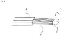
- FIG. 1 is a schematic diagram showing a bonded structure 1.
- the bonded structure 1 is a structure in which conductors 5 of a plurality of wires 3 are ultrasonically bonded to each other.
- outer peripheries of the conductors 5 are covered with an insulation coating.
- the insulation coating is removed to a predetermined extent, exposing the inner conductors 5.
- Each conductor 5 is made of a plurality of wires twisted together, for example.
- the conductor 5 may be a single wire.
- the plurality of conductors 5 include conductors that are relatively difficult to deform and conductors that are relatively easy to deform. In other words, there are two or more types of wires 3 made up of conductors of different materials.
- the conductors 5 in each of the plurality of wires 3 are arranged facing in the same direction.
- a conductor joint 7 is formed where the conductors 5 are ultrasonically bonded to each other.
- the conductors 5 are integrated at the conductor joint 7.
- the wires 3 do not necessarily have to all be oriented in the same direction, but it is desirable that at least some of the wires 3 are oriented in the same direction. In the figures, no wires are ahead of the conductor joint 7, but no limitation is intended.
- FIG. 2 shows an ultrasonic bonding device 9 for bonding conductors by ultrasonic bonding.
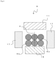
- the ultrasonic bonding device 9 includes an anvil 15, a horn 11 arranged opposing the anvil 15, and a pair of gathers 17 opposing each other in a direction orthogonal to the direction in which the anvil 15 and the horn 11 oppose each other. Note that, a vibration source that applies vibration to the horn 11 is omitted from the figure.
- the plurality of wires 3 include wires 3 made up of a conductor 5a, which is relatively difficult to deform, and wires 3 made up of a conductor 5b, which is relatively easy to deform.
- the material that is difficult to deform include a material with a relatively high melting point, a material with a high elastic modulus, a material with a high hardness, and a material with a high tensile strength.
- the material that is difficult to deform is a material with a relatively small amount of deformation when subjected to the same compressive force during ultrasonic bonding.
- the conductor 5a which is relatively difficult to deform
- the conductor 5b which is relatively easy to deform
- the conductor 5b is a conductor containing aluminum as a main component
- the conductor 5a which is relatively difficult to deform
- the conductor 5b which is relatively easy to deform
- the conductor 5b which is relatively easy to deform
- the conductor 5a may be a conductor made mainly of a relatively hard aluminum (such as an aluminum alloy)
- the conductor 5b which is relatively easy to deform
- the quantity of additives may be increased relative to the conductor 5a, which is relatively difficult to deform.
- an assembly formed by gathering the conductors 5a and 5b of the plurality of wires 3 is arranged between the anvil 15 and the horn 11, which oppose each other in the up-down direction.
- the gathers 17 are arranged on either side of the assembly of the conductors 5a and 5b.
- the assembly of the conductors 5a and 5b is sandwiched between the anvil 15 and the horn 11 in the up-down direction and sandwiched between the pair of gathers 17 in the width direction.
- FIG. 2 shows an example in which the conductor 5b is arranged on the anvil 15 side and the conductor 5a is arranged on the horn 11 side, but the conductor 5a may be arranged on the anvil 15 side and the conductor 5b may be arranged on the horn 11 side.
- ultrasonic vibration is applied to the assembly by the horn 11 in a direction substantially perpendicular to the direction of pressure (direction of the arrow B in the figure) while the anvil 15 and the horn 11 sandwich the assembly in the up-down direction and apply pressure collectively (direction of the arrow B in the figure).
- the ultrasonic vibration direction is the width direction of the assembly (direction of the arrow C in the figure) or the axial direction of the wires.
- the arrangement of the wires 3, which are made of different materials, is substantially line symmetrical with respect to the center line A in the vibration direction.
- the top surface of the anvil 15 is flat but may be formed with a round shape on both sides. That is, at the conductor joint 7, a portion corresponding to the corner between the gather 17 and the anvil 15 may be formed with a round shape.
- the bottom surface of the anvil 15 on the horn side is flat but may also be formed with a round shape on both sides.
- FIGS. 4A to 4D Such a symmetrical arrangement is not limited to the example shown in FIG. 2 .
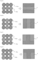
- the left figures show other arrangements of the conductors 5a and 5b, and the right figures shows the conductor joint 7 after welding (the same applies to the following figures). The same is also true when swapping the arrangement of the conductors 5a and 5b, as described above.
- FIG. 4A is a diagram showing a state where the conductors 5a are arranged on both sides in the width direction and the conductors 5b are arranged between the conductors 5a.
- the conductors 5a and 5b may be divided in the left-right direction instead of being gathered in the up-down direction.
- four conductors 5a are divided into two.
- at least one type of wire is not gathered together in one assembly but is instead separated across several different locations.
- the wires 3 made up of the conductors 5b that are relatively easy to deform between the wires 3 made up of the conductors 5a that are relatively difficult to deform without the conductors 5a that are relatively difficult to deform being adjacent to each other.
- the conductors 5a that are relatively difficult to deform are less deformable, the surface oxide of the conductors 5a may not be sufficiently destroyed, resulting in variations in bonding strength.
- the bonding length between the conductors 5a can be reduced and the bonding length between the conductors 5a and 5b can be increased compared to when the conductors 5a are gathered into one assembly.
- the bonding strength can be stabilized.
- the same effect can be achieved by arranging the conductors 5a with the fewer number of conductors so that they are separated and not adjacent to each other, even when the numbers of conductors 5a and 5b are not equal, as shown in FIG. 4C .
- the separated conductors 5a may be arranged on the anvil side instead of the horn side, as shown in FIG. 4D .
- the number of conductors in the up-down direction and the width directions may be the same.
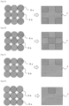
- the cross-sectional shape of the conductor joint may be square. Even with this configuration, it is desirable to separate and arrange at least either of the conductors 5a or 5b into multiple regions, rather than gathering the conductors 5a and 5b into the respective assemblies. In this case, the conductors 5a and 5b may be separated vertically, or may be separated left and right, as shown in FIG. 5B .
- the conductors 5a and 5b may be arranged in a T-shape or an inverted T-shape, as shown in FIGS. 5C and 5D . Further, the conductors 5a and 5b may be separated in different numbers. For example, if separating the conductor 5a into two different parts, part of the conductor 5a may be separated into three and another part of the conductor 5a may be separated into one, as shown in FIGS. 6A and 6B .
- both the conductors 5a and 5b can be separated into individual sections.
- one conductor 5a e.g., the conductor that is relatively difficult to deform
- the sizes of the conductors 5a and 5b need not be identical.
- the conductor 5a may be arranged at the center of the conductors 5b, as shown in FIG. 8A .
- the conductor 5a may be arranged above the conductor 5b, as shown in FIG. 8B . That is, for example, the conductor 5a that is relatively difficult to deform may be arranged so that it is not exposed at the periphery but covered from all sides by the other conductors 5b, or the conductor 5a may be arranged so that it is exposed on the horn side.
- the conductors 5a may be arranged above, below, and at the center of the conductors 5b, as shown in FIG. 8C . In any case, the conductor 5a may be arranged between the conductors 5b in a state where the conductors 5b are aligned.
- the number and arrangement of the wires are not limited to the examples described above.
- conductors 5a and 5b of two different materials were gathered to form the conductor joint 7
- conductors 5a, 5b, and 5c of three or more different materials may be intermixed, as shown in FIGS. 9A to 9D , for example.
- high bonding strength can be achieved by arranging conductors of different materials with different ease of deformation so that they are symmetrical with respect to the center line in the width direction (ultrasonic vibration direction). Note that, in this case, it is also desirable to separate the conductors that are most difficult to deform into multiple sections.
- two or more types of wires are intermixed together with respect to the width direction of the conductor joint 7 (the direction in which the wires are sandwiched by the pair of gathers), at least at a portion along the center line with respect to the width direction.
- the interfaces between the wires will be linear with respect to the width direction, and the relatively softer material will soften first, which may not guarantee bonding strength at the interface between the different wire types.
- the arrangement of the conductors was changed, and the bonding strength was evaluated.
- the conductors were arranged in each arrangement and ultrasonic bonding was performed in a range of 10 mm in length. With the wires fixed to the bonded structure, one of the wires was pulled in a 180-degree direction at 100 mm/min, and the maximum load at which the conductor joint was torn was defined as the bonding strength. The results are shown in FIGS. 10 and 11 .
- the copper wires in Examples 1 and 3 and Comparative Examples 1, 3, and 7 in the figures are tough pitch copper wires with a nominal cross-sectional area of 0.35 sq.
- the copper wires with smaller diameters in Examples 4 and 5 and Comparative Examples 4 and 5 are Cu alloy wires with Sn 0.7 mass% with a nominal cross-sectional area of 0.13 sq.
- the soft aluminum wire is an aluminum alloy (A1070) wire with a nominal cross-sectional area of 0.75 sq
- the hard aluminum wire is an A6061 aluminum alloy wire with a nominal cross section of 0.5 sq.
- Examples 1 to 7 in which the conductors are arranged symmetrically in the width direction, achieved higher bonding strength than Comparative Examples 1 to 6, in which the conductors are arranged asymmetrically.
- FIG. 2 and FIGS. 4 to 9 higher bonding strength was achieved compared to the Comparative Examples, particularly by separating and arranging one type of conductors A (harder conductor) so that they are not adjacent to each other in the up-down and left-right directions, as in Examples 1 to 6.
- relatively hard conductors or relatively soft conductors may be arranged in at least a portion of a joint portion of the mold (between the anvil 15 and the gather 17, and between the horn 11 and the gather 17).
Landscapes
- Engineering & Computer Science (AREA)
- Manufacturing & Machinery (AREA)
- Manufacturing Of Electrical Connectors (AREA)
- Connections Effected By Soldering, Adhesion, Or Permanent Deformation (AREA)
Abstract
Provided is a bonded structure in which conductors of a plurality of wires is ultrasonically bonded together. Conductors (5a) that are relatively difficult to deform are intermixed with conductors (5b) that are relatively easy to deform. In other words, two or more types of the wires made up of conductors of different materials are intermixed. In an axial view of the wires, when an ultrasonic bonding direction is an up-down direction of a conductor joint, and a direction orthogonal to the ultrasonic bonding direction is a width direction of the conductor joint, the conductors (5a, 5b) of different materials are arranged substantially line symmetrical with respect to a center line (A) in the width direction.
Description
- The present invention relates to a conductor-bonded structure in which a plurality of wire conductors is ultrasonically bonded to each other, and a method for ultrasonically bonding conductors.
- Wire harnesses used in automobiles and other vehicles include multiple wires bonded together. One method used to bond these wires is as follows. For example, insulation coating on multiple insulated wires is stripped off to predetermined lengths for each wire to expose the conductors, the exposed conductors are twisted together in the same direction, and the twisted portions are welded together by ultrasonically welding to connect the wires (e.g., Patent Literature 1).
- Patent Literature 1:
JP 2005-322544 A - However, instead of only bonding conductors that are all made of the same material, there is sometimes a need to bond conductors made of different materials. In such cases, it may be difficult to ensure sufficient bonding strength.
- It is an object of the present invention to provide a conductor-bonded structure and a method for ultrasonically bonding conductors capable of ultrasonically bonding conductors of different materials with high bonding strength.
- In order to achieve the object described above, a first invention is a conductor-bonded structure in which conductors of a plurality of wires are ultrasonically bonded, in which two or more types of the wires made up of conductors of different materials are intermixed, when viewed from an axial direction of the wire, an ultrasonic bonding direction is an up-down direction of a conductor joint, and a direction orthogonal to the ultrasonic bonding direction is a width direction of the conductor joint, the wires made of different materials are arranged substantially line symmetrical with respect to a center line in the width direction, and the two or more types of wires are intermixed in the width direction of the conductor joint, at least at a portion along the center line.
- When viewed from the axial direction of the wire, at least one type of the wires is desirably separated across several different locations.
- When viewed from the axial direction of the wire, at least one type of the wires may be separated in the up-down direction of the conductor joint.
- Of the wires, a wire made up of conductors that are relatively easy to deform may be arranged between wires made up of conductors that are relatively difficult to deform.
- The conductor that is relatively difficult to deform may be a conductor containing copper as a main component, and the conductor that is relatively easy to deform may be a conductor containing aluminum as a main component.
- The conductor that is relatively difficult to deform may be a conductor containing relatively hard aluminum as a main component, and the conductor that is relatively easy to deform may be a conductor containing relatively soft aluminum as a main component.
- When viewed from the axial direction of the wire, one type of the wires may be arranged at the center in the width direction.
- According to the first invention, high bonding strength can be achieved by arranging wires made of different materials substantially line symmetrical with respect to the center line in the width direction.
- In particular, higher bonding strength can be achieved by separating at least one type of the wires across several different locations (not gathering the wires into one assembly) when viewing the wires from the axial direction of the wire. For example, by separating one type of the wires in the up-down direction of the conductor joint, wires that differ in the up-down direction can be bonded with higher strength.
- For example, it may be difficult to achieve high bonding strength between wires made up of conductors that are relatively difficult to deform as compared to wires made up of conductors that are relatively easy to deform. This is because the conductor surfaces do not sufficiently deform and the oxide film on the surfaces of the conductors affect the bonding strength. On the other hand, increasing the bonding energy of ultrasonic bonding can cause the mold and the conductors to adhere to each other, for example.
- In contrast, by arranging conductors that are relatively easy to deform between conductors that are relatively difficult to deform, higher bonding strength can be achieved than when bonding wires made up of conductors that are relatively difficult to deform.
- For example, if conductors that are relatively easy to deform are gathered together on one side and conductors that are relatively difficult to deform are gathered together on the other side and all the conductors are bonded, in the initial stage of bonding, only the conductors that are relatively easy to deform will deform and the conductors that are relatively difficult to deform will not bond. In other words, bonding progresses only on one side of the wire assembly. In contrast, by distributing the conductors that are relatively difficult to deform and the conductors that are relatively easy to deform, bonding can be progressed throughout the entire wire assembly from the initial stage of bonding. Therefore, it is possible to reduce variation in bonding strength and ensure stable strength throughout the assembly.
- In particular, when creating an assembly of conductors containing aluminum as a main component and conductors containing copper as a main component, the conductors containing copper as a main component are relatively difficult to deform. Thus, the above effect can be achieved more reliably when creating an assembly of conductors containing aluminum as a main component and conductors containing copper as a main component.
- The same effect can also be reliably achieved when creating an assembly of conductors containing a hard aluminum as a main component and conductors containing a soft aluminum as a main component.
- A second invention is a method for ultrasonically bonding conductors of a plurality of wires together, the method using an anvil, a horn arranged opposing the anvil, and a pair of gathers opposing each other in a direction orthogonal to the direction in which the anvil and the horn oppose each other, the method including: sandwiching an assembly formed by gathering a plurality of the conductors between the anvil, the horn, and the gathers, in which, when applying vibration to the assembly in a direction substantially perpendicular to an axial direction of the wire while applying pressure, when viewed from the axial direction of the wire, the wires made of different materials are arranged substantially line symmetrical with respect to a center line in a vibration direction, and two or more types of the wires are intermixed in a direction in which the assembly is sandwiched by the pair of gathers, at least at a portion along the center line.
- According to the second invention, high bonding strength can be achieved by arranging wires made of different materials substantially line symmetrical with respect to the center line in the width direction.
- The present invention provides a conductor-bonded structure and a method for ultrasonically bonding conductors capable of ultrasonically bonding conductors of different materials with high bonding strength.
-
-
FIG. 1 is a diagram showing a bondedstructure 1. -
FIG. 2 is a diagram showing a method for bondingconductors -
FIG. 3 is a diagram showing a state in which theconductors -
FIG. 4A is a diagram showing another arrangement of theconductors -
FIG. 4B is a diagram showing another arrangement of theconductors -
FIG. 4C is a diagram showing another arrangement of theconductors -
FIG. 4D is a diagram showing another arrangement of theconductors -
FIG. 5A is a diagram showing another arrangement of theconductors -
FIG. 5B is a diagram showing another arrangement of theconductors -
FIG. 5C is a diagram showing another arrangement of theconductors -
FIG. 5D is a diagram showing another arrangement of theconductors -
FIG. 6A is a diagram showing another arrangement of theconductors -
FIG. 6B is a diagram showing another arrangement of theconductors -
FIG. 6C is a diagram showing another arrangement of theconductors -
FIG. 6D is a diagram showing another arrangement of theconductors -
FIG. 7A is a diagram showing another arrangement of theconductors -
FIG. 7B is a diagram showing another arrangement of theconductors -
FIG. 7C is a diagram showing another arrangement of theconductors -
FIG. 7D is a diagram showing another arrangement of theconductors -
FIG. 8A is a diagram showing another arrangement of theconductors -
FIG. 8B is a diagram showing another arrangement of theconductors -
FIG. 8C is a diagram showing another arrangement of theconductors -
FIG. 9A is a diagram showing another arrangement of theconductors -
FIG. 9B is a diagram showing another arrangement of theconductors -
FIG. 9C is a diagram showing another arrangement of theconductors -
FIG. 9D is a diagram showing another arrangement of theconductors -
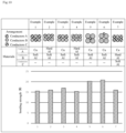
FIG. 10 is a diagram showing results of bonding strength measurement. -
FIG. 11 is a diagram showing results of bonding strength measurement. - Now, embodiments of the present invention will be described with reference to the figures.
FIG. 1 is a schematic diagram showing a bondedstructure 1. The bondedstructure 1 is a structure in whichconductors 5 of a plurality ofwires 3 are ultrasonically bonded to each other. In each of thewires 3, outer peripheries of theconductors 5 are covered with an insulation coating. At the end of eachwire 3, the insulation coating is removed to a predetermined extent, exposing theinner conductors 5. - Each
conductor 5 is made of a plurality of wires twisted together, for example. Theconductor 5 may be a single wire. As will be described in detail later, the plurality ofconductors 5 include conductors that are relatively difficult to deform and conductors that are relatively easy to deform. In other words, there are two or more types ofwires 3 made up of conductors of different materials. - The
conductors 5 in each of the plurality ofwires 3 are arranged facing in the same direction. At the leading edge of theconductors 5, aconductor joint 7 is formed where theconductors 5 are ultrasonically bonded to each other. In other words, theconductors 5 are integrated at theconductor joint 7. Thewires 3 do not necessarily have to all be oriented in the same direction, but it is desirable that at least some of thewires 3 are oriented in the same direction. In the figures, no wires are ahead of theconductor joint 7, but no limitation is intended. - Next, a method for ultrasonically bonding the
conductors 5 of the plurality ofwires 3 by using an ultrasonic bonding device will be described.FIG. 2 shows anultrasonic bonding device 9 for bonding conductors by ultrasonic bonding. Theultrasonic bonding device 9 includes ananvil 15, a horn 11 arranged opposing theanvil 15, and a pair of gathers 17 opposing each other in a direction orthogonal to the direction in which theanvil 15 and the horn 11 oppose each other. Note that, a vibration source that applies vibration to the horn 11 is omitted from the figure. - In this embodiment, the plurality of
wires 3 includewires 3 made up of aconductor 5a, which is relatively difficult to deform, andwires 3 made up of aconductor 5b, which is relatively easy to deform. Examples of the material that is difficult to deform include a material with a relatively high melting point, a material with a high elastic modulus, a material with a high hardness, and a material with a high tensile strength. In other words, the material that is difficult to deform is a material with a relatively small amount of deformation when subjected to the same compressive force during ultrasonic bonding. - As the
conductors conductor 5a, which is relatively difficult to deform, is a conductor containing copper as a main component, and theconductor 5b, which is relatively easy to deform, is a conductor containing aluminum as a main component. - In a configuration where the
conductors conductor 5a, which is relatively difficult to deform, may be a conductor made mainly of a relatively hard aluminum (such as an aluminum alloy), and theconductor 5b, which is relatively easy to deform, may be a conductor made mainly of a relatively soft aluminum (such as pure aluminum). Further, if the ease of deformation varies depending on additives or other factors, for example, the quantity of additives may be increased relative to theconductor 5a, which is relatively difficult to deform. - To perform ultrasonic bonding, first, an assembly formed by gathering the
conductors wires 3 is arranged between theanvil 15 and the horn 11, which oppose each other in the up-down direction. The gathers 17 are arranged on either side of the assembly of theconductors conductors anvil 15 and the horn 11 in the up-down direction and sandwiched between the pair of gathers 17 in the width direction. - Viewed from the axial direction of
wire 3, when an ultrasonic bonding direction is taken as the up-down direction of the conductor joint (up-down direction inFIG. 2 ) and a direction orthogonal to this direction is taken as the width direction of the conductor joint (right-left direction inFIG. 2 ), the arrangement of theconductors - The figures referred to below also include cases in which the arrangement of the
conductors FIG. 2 shows an example in which theconductor 5b is arranged on theanvil 15 side and theconductor 5a is arranged on the horn 11 side, but theconductor 5a may be arranged on theanvil 15 side and theconductor 5b may be arranged on the horn 11 side. - Next, as shown in
FIG. 3 , in a state where the width direction of the assembly is restricted by the assembly being sandwiched between the gathers 17, ultrasonic vibration is applied to the assembly by the horn 11 in a direction substantially perpendicular to the direction of pressure (direction of the arrow B in the figure) while theanvil 15 and the horn 11 sandwich the assembly in the up-down direction and apply pressure collectively (direction of the arrow B in the figure). In other words, the ultrasonic vibration direction is the width direction of the assembly (direction of the arrow C in the figure) or the axial direction of the wires. Therefore, when viewed from the axial direction of thewires 3, the arrangement of thewires 3, which are made of different materials, is substantially line symmetrical with respect to the center line A in the vibration direction. With this configuration, it is possible to form aconductor joint 7 in which the plurality ofconductors conductor joint 7, the up-down direction and the left-right direction of theconductor joint 7 are specified. - In the illustrated example, the top surface of the
anvil 15 is flat but may be formed with a round shape on both sides. That is, at theconductor joint 7, a portion corresponding to the corner between the gather 17 and theanvil 15 may be formed with a round shape. Similarly, the bottom surface of theanvil 15 on the horn side is flat but may also be formed with a round shape on both sides. - According to this embodiment, when the plurality of
conductors conductor joint 7, high bonding strength can be achieved by arranging theconductor 5a, which is relatively difficult to deform, and theconductor 5b, which is relatively easy to deform, so that they are symmetrical with respect to the center line A in the width direction (ultrasonic vibration direction). - Such a symmetrical arrangement is not limited to the example shown in
FIG. 2 . For example, inFIGS. 4A to 4D , the left figures show other arrangements of theconductors conductor joint 7 after welding (the same applies to the following figures). The same is also true when swapping the arrangement of theconductors -
FIG. 4A is a diagram showing a state where theconductors 5a are arranged on both sides in the width direction and theconductors 5b are arranged between theconductors 5a. With this configuration, theconductors conductors 5a are divided into two. In other words, when viewed from the axial direction of thewire 3, at least one type of wire is not gathered together in one assembly but is instead separated across several different locations. - When creating an assembly of the
same type conductors 5a and thesame type conductors 5b and theconductors conductors conductors conductors conductors conductors conductors - Note that, it is more desirable to arrange the
wires 3 made up of theconductors 5b that are relatively easy to deform between thewires 3 made up of theconductors 5a that are relatively difficult to deform, without theconductors 5a that are relatively difficult to deform being adjacent to each other. For example, since theconductors 5a that are relatively difficult to deform are less deformable, the surface oxide of theconductors 5a may not be sufficiently destroyed, resulting in variations in bonding strength. On the other hand, by arranging thewires 3 made up of theconductors 5b that are relatively easy to deform between thewires 3 made up of theconductors 5a that are relatively difficult to deform, the bonding length between theconductors 5a can be reduced and the bonding length between theconductors conductors 5a are gathered into one assembly. Thus, the bonding strength can be stabilized. - As shown in
FIG. 4B , it is more effective if all theconductors wire 3 is separated in the up-down direction of theconductor joint 7 and thesame type conductors 5a or thesame type conductors 5b are arranged so that they are not arranged being adjacent to each other vertically and horizontally, it is possible to further stabilize bonding strength. - The same effect can be achieved by arranging the
conductors 5a with the fewer number of conductors so that they are separated and not adjacent to each other, even when the numbers ofconductors FIG. 4C . In this case, the separatedconductors 5a may be arranged on the anvil side instead of the horn side, as shown inFIG. 4D . - As shown in
FIG. 5A , the number of conductors in the up-down direction and the width directions may be the same. In other words, the cross-sectional shape of the conductor joint may be square. Even with this configuration, it is desirable to separate and arrange at least either of theconductors conductors conductors FIG. 5B . - Instead of arranging the
conductors conductors FIGS. 5C and 5D . Further, theconductors conductor 5a into two different parts, part of theconductor 5a may be separated into three and another part of theconductor 5a may be separated into one, as shown inFIGS. 6A and 6B . - As shown in
FIGS. 6C and 6D , it is desirable that oneconductor 5a is completely separated into individual sections. In this case, arranging theconductors 5b in a row between theconductors 5a, which are separated into a top and a bottom, theconductors conductors 5a do not line up even in diagonal directions, without theconductors 5a coming into contact with each other during bonding. - The same effect can be achieved by separating the
conductor 5a into places at four corners, as shown inFIG. 7A . Further, as shown inFIG. 7B , if theconductors conductors FIGS. 7C and 7D , oneconductor 5a (e.g., the conductor that is relatively difficult to deform) may be arranged only at the top row (the horn 11 side) and theconductors 5a may not be adjacent to each other. - The sizes of the
conductors conductor 5a, which has a relatively small size, theconductor 5a may be arranged at the center of theconductors 5b, as shown inFIG. 8A . Alternatively, theconductor 5a may be arranged above theconductor 5b, as shown inFIG. 8B . That is, for example, theconductor 5a that is relatively difficult to deform may be arranged so that it is not exposed at the periphery but covered from all sides by theother conductors 5b, or theconductor 5a may be arranged so that it is exposed on the horn side. If there is more than oneconductor 5a, theconductors 5a may be arranged above, below, and at the center of theconductors 5b, as shown inFIG. 8C . In any case, theconductor 5a may be arranged between theconductors 5b in a state where theconductors 5b are aligned. - The number and arrangement of the wires are not limited to the examples described above. In the explanation above, an example in which
conductors conductor joint 7 was described, butconductors FIGS. 9A to 9D , for example. In this case, too, high bonding strength can be achieved by arranging conductors of different materials with different ease of deformation so that they are symmetrical with respect to the center line in the width direction (ultrasonic vibration direction). Note that, in this case, it is also desirable to separate the conductors that are most difficult to deform into multiple sections. - It is desirable for two or more types of wires to be intermixed together with respect to the width direction of the conductor joint 7 (the direction in which the wires are sandwiched by the pair of gathers), at least at a portion along the center line with respect to the width direction. For example, when wires of each type are aligned in a row (or multiple rows) over the entire width direction, as shown in
FIGS. 2 and5A , the interfaces between the wires will be linear with respect to the width direction, and the relatively softer material will soften first, which may not guarantee bonding strength at the interface between the different wire types. In particular, when the wire types are aligned parallel to the vibration direction of the horn 11 (i.e., the width direction of the wire joint), vibration especially in the horizontal direction during ultrasonic welding is less conducive to improving bonding strength. Therefore, by arranging each wire so that multiple wire types are intermixed in the width direction at least for a portion along the up-down direction of theconductor joint 7, bonding strength at the interface between the different wire types can be ensured. - The arrangement of the conductors was changed, and the bonding strength was evaluated. The conductors were arranged in each arrangement and ultrasonic bonding was performed in a range of 10 mm in length. With the wires fixed to the bonded structure, one of the wires was pulled in a 180-degree direction at 100 mm/min, and the maximum load at which the conductor joint was torn was defined as the bonding strength. The results are shown in
FIGS. 10 and11 . - The copper wires in Examples 1 and 3 and Comparative Examples 1, 3, and 7 in the figures are tough pitch copper wires with a nominal cross-sectional area of 0.35 sq. The copper wires with smaller diameters in Examples 4 and 5 and Comparative Examples 4 and 5 are Cu alloy wires with Sn 0.7 mass% with a nominal cross-sectional area of 0.13 sq. The soft aluminum wire is an aluminum alloy (A1070) wire with a nominal cross-sectional area of 0.75 sq, and the hard aluminum wire is an A6061 aluminum alloy wire with a nominal cross section of 0.5 sq.
- As shown in
FIGS. 10 and11 , Examples 1 to 7, in which the conductors are arranged symmetrically in the width direction, achieved higher bonding strength than Comparative Examples 1 to 6, in which the conductors are arranged asymmetrically. Although a detailed description will not be provided, inFIG. 2 andFIGS. 4 to 9 , higher bonding strength was achieved compared to the Comparative Examples, particularly by separating and arranging one type of conductors A (harder conductor) so that they are not adjacent to each other in the up-down and left-right directions, as in Examples 1 to 6. - Embodiments have been described above with reference to the accompanying figures, but the technical scope of the present invention is not affected by the above-described embodiments. It will be clear to a person skilled in the art to conceive of various changes or modifications within the scope of the technical concept described in the claims, which are naturally understood to be within the technical scope of the present invention.
- For example, relatively hard conductors or relatively soft conductors may be arranged in at least a portion of a joint portion of the mold (between the
anvil 15 and the gather 17, and between the horn 11 and the gather 17). -
- 1 Bonded structure
- 3 Wire
- 5, 5a, 5b, 5c Conductor
- 7 Conductor joint
- 9 Ultrasonic bonding device
- 11 Horn
- 15 Anvil
- 17 Gather
Claims (8)
- A conductor-bonded structure in which conductors of a plurality of wires are ultrasonically bonded, whereintwo or more types of the wires made up of conductors of different materials are intermixed;when viewed from an axial direction of the wire, an ultrasonic bonding direction is an up-down direction of a conductor joint, and a direction orthogonal to the ultrasonic bonding direction is a width direction of the conductor joint;the wires made of different materials are arranged substantially line symmetrical with respect to a center line in the width direction; andthe two or more types of the wires are intermixed in the width direction of the conductor joint, at least at a portion along the center line.
- The conductor-bonded structure according to claim 1, wherein
when viewed from the axial direction of the wire, at least one type of the wires is separated across several different locations. - The conductor-bonded structure according to claim 2, wherein
when viewed from the axial direction of the wire, at least one type of the wires is separated in the up-down direction of the conductor joint. - The conductor-bonded structure according to claim 2 or 3, wherein
of the wires, a wire made up of conductors that are relatively easy to deform is arranged between wires made up of conductors that are relatively difficult to deform. - The conductor-bonded structure according to claim 4, wherein
the conductor that is relatively difficult to deform is a conductor containing copper as a main component, and the conductor that is relatively easy to deform is a conductor containing aluminum as a main component. - The conductor-bonded structure according to claim 4, wherein
the conductor that is relatively difficult to deform is a conductor containing relatively hard aluminum as a main component, and the conductor that is relatively easy to deform is a conductor containing relatively soft aluminum as a main component. - The conductor-bonded structure according to claim 1, wherein
when viewed from the axial direction of the wire, one type of the wires is arranged at the center in the width direction. - A method for ultrasonically bonding conductors of a plurality of wires together, the method using an anvil, a horn arranged opposing the anvil, and a pair of gathers opposing each other in a direction orthogonal to the direction in which the anvil and the horn oppose each other, the method comprising:sandwiching an assembly formed by gathering a plurality of the conductors between the anvil, the horn, and the gathers, whereinwhen applying vibration to the assembly in a direction substantially perpendicular to an axial direction of the wire while applying pressure, when viewed from the axial direction of the wire, the wires made of different materials are arranged substantially line symmetrical with respect to a center line in a vibration direction, and two or more types of the wires are intermixed in a direction in which the assembly is sandwiched by the pair of gathers, at least at a portion along the center line.
Applications Claiming Priority (2)
| Application Number | Priority Date | Filing Date | Title |
|---|---|---|---|
| JP2022138133 | 2022-08-31 | ||
| PCT/JP2023/031813 WO2024048719A1 (en) | 2022-08-31 | 2023-08-31 | Conductor-bonded structure and method for ultrasonically bonding conductors |
Publications (1)
| Publication Number | Publication Date |
|---|---|
| EP4583316A1 true EP4583316A1 (en) | 2025-07-09 |
Family
ID=90099826
Family Applications (1)
| Application Number | Title | Priority Date | Filing Date |
|---|---|---|---|
| EP23860481.3A Pending EP4583316A1 (en) | 2022-08-31 | 2023-08-31 | Conductor-bonded structure and method for ultrasonically bonding conductors |
Country Status (5)
| Country | Link |
|---|---|
| US (1) | US20250149808A1 (en) |
| EP (1) | EP4583316A1 (en) |
| JP (1) | JPWO2024048719A1 (en) |
| CN (1) | CN119111020A (en) |
| WO (1) | WO2024048719A1 (en) |
Family Cites Families (8)
| Publication number | Priority date | Publication date | Assignee | Title |
|---|---|---|---|---|
| JP4728592B2 (en) | 2004-05-11 | 2011-07-20 | 古河電気工業株式会社 | Insulated wire connection and insulated wire connection method |
| JP5196562B2 (en) * | 2008-11-06 | 2013-05-15 | 矢崎総業株式会社 | Connection method of aluminum wire and copper wire and connection body thereof |
| JPWO2010150351A1 (en) * | 2009-06-23 | 2012-12-06 | 東芝三菱電機産業システム株式会社 | Electrode substrate |
| DE102013219150A1 (en) * | 2013-09-24 | 2015-04-09 | Elringklinger Ag | Method for producing an electrically conductive connection between an electrical line and an electrically conductive component |
| JP6013417B2 (en) * | 2014-09-03 | 2016-10-25 | 矢崎総業株式会社 | Covered wire joining method |
| JP2017076497A (en) * | 2015-10-14 | 2017-04-20 | 株式会社オートネットワーク技術研究所 | Cluster of a plurality of wires and manufacturing method thereof |
| JP7132699B2 (en) * | 2017-06-21 | 2022-09-07 | 古河電気工業株式会社 | Wire connection structure and manufacturing method thereof |
| JP2020064737A (en) * | 2018-10-16 | 2020-04-23 | 株式会社オートネットワーク技術研究所 | Connection structure of electric wire, and connection method of electric wire |
-
2023
- 2023-08-31 EP EP23860481.3A patent/EP4583316A1/en active Pending
- 2023-08-31 CN CN202380040048.2A patent/CN119111020A/en active Pending
- 2023-08-31 JP JP2024544560A patent/JPWO2024048719A1/ja active Pending
- 2023-08-31 WO PCT/JP2023/031813 patent/WO2024048719A1/en not_active Ceased
-
2025
- 2025-01-08 US US19/013,827 patent/US20250149808A1/en active Pending
Also Published As
| Publication number | Publication date |
|---|---|
| US20250149808A1 (en) | 2025-05-08 |
| JPWO2024048719A1 (en) | 2024-03-07 |
| WO2024048719A1 (en) | 2024-03-07 |
| CN119111020A (en) | 2024-12-10 |
Similar Documents
| Publication | Publication Date | Title |
|---|---|---|
| US10998701B2 (en) | Wire bonding method and bonded wire | |
| CN108701951B (en) | Ultrasonic welding jig, method of manufacturing wire with terminal, and wire with terminal | |
| KR101221744B1 (en) | Terminal connector and electric wire with terminal connector | |
| EP2290747B1 (en) | Metal terminal fitting and electric wire with terminal | |
| US20110198122A1 (en) | Electric wire with terminal and method of manufacturing the same | |
| EP2549591B1 (en) | Ultrasonic welding method and welding section | |
| JP5400318B2 (en) | Crimp terminal for aluminum wire | |
| US10276283B2 (en) | Manufacturing method for terminal-equipped electric wire | |
| DE102019213845A1 (en) | CONNECTING WIRE CONNECTING METHOD AND CONNECTED CONNECTING WIRE | |
| JP2020013633A (en) | Wire with terminal and method of manufacturing the same | |
| US11462842B2 (en) | Wire connection structure and wire connection method | |
| US11791599B2 (en) | Electric cable with terminal and method for manufacturing electric cable with terminal | |
| JP7751621B2 (en) | Horn and ultrasonic bonding equipment | |
| US20210399443A1 (en) | Wire connection structure and wire connection method | |
| US20250149808A1 (en) | Conductor-bonded structure and method for ultrasonically bonding conductors | |
| JPH05217429A (en) | Tape electric wire and method of manufacturing the same | |
| JP2001291571A (en) | Electro-conductive material and its manufacturing method | |
| JP3395373B2 (en) | Wire splice structure | |
| JPH0982375A (en) | Electric wire connecting method | |
| JP7547245B2 (en) | Conductor joining structure and method for ultrasonically joining a conductor | |
| JP7585094B2 (en) | Conductor joining structure and method for ultrasonically joining a conductor | |
| JP7536688B2 (en) | Conductor joining structure and method for ultrasonically joining a conductor | |
| JP4894624B2 (en) | Conductor connection method | |
| JP7598784B2 (en) | Conductor joining structure and method for ultrasonically joining a conductor | |
| WO2025013597A1 (en) | Electric wire connection structure |
Legal Events
| Date | Code | Title | Description |
|---|---|---|---|
| STAA | Information on the status of an ep patent application or granted ep patent |
Free format text: STATUS: THE INTERNATIONAL PUBLICATION HAS BEEN MADE |
|
| PUAI | Public reference made under article 153(3) epc to a published international application that has entered the european phase |
Free format text: ORIGINAL CODE: 0009012 |
|
| STAA | Information on the status of an ep patent application or granted ep patent |
Free format text: STATUS: REQUEST FOR EXAMINATION WAS MADE |
|
| 17P | Request for examination filed |
Effective date: 20250129 |
|
| AK | Designated contracting states |
Kind code of ref document: A1 Designated state(s): AL AT BE BG CH CY CZ DE DK EE ES FI FR GB GR HR HU IE IS IT LI LT LU LV MC ME MK MT NL NO PL PT RO RS SE SI SK SM TR |
|
| DAV | Request for validation of the european patent (deleted) | ||
| DAX | Request for extension of the european patent (deleted) |