EP4583284A1 - Battery module and battery pack comprising same - Google Patents
Battery module and battery pack comprising same Download PDFInfo
- Publication number
- EP4583284A1 EP4583284A1 EP24849535.0A EP24849535A EP4583284A1 EP 4583284 A1 EP4583284 A1 EP 4583284A1 EP 24849535 A EP24849535 A EP 24849535A EP 4583284 A1 EP4583284 A1 EP 4583284A1
- Authority
- EP
- European Patent Office
- Prior art keywords
- connection part
- pocket parts
- battery
- flange
- Prior art date
- Legal status (The legal status is an assumption and is not a legal conclusion. Google has not performed a legal analysis and makes no representation as to the accuracy of the status listed.)
- Pending
Links
Images




Classifications
-
- H—ELECTRICITY
- H01—ELECTRIC ELEMENTS
- H01M—PROCESSES OR MEANS, e.g. BATTERIES, FOR THE DIRECT CONVERSION OF CHEMICAL ENERGY INTO ELECTRICAL ENERGY
- H01M50/00—Constructional details or processes of manufacture of the non-active parts of electrochemical cells other than fuel cells, e.g. hybrid cells
- H01M50/20—Mountings; Secondary casings or frames; Racks, modules or packs; Suspension devices; Shock absorbers; Transport or carrying devices; Holders
- H01M50/258—Modular batteries; Casings provided with means for assembling
-
- H—ELECTRICITY
- H01—ELECTRIC ELEMENTS
- H01M—PROCESSES OR MEANS, e.g. BATTERIES, FOR THE DIRECT CONVERSION OF CHEMICAL ENERGY INTO ELECTRICAL ENERGY
- H01M50/00—Constructional details or processes of manufacture of the non-active parts of electrochemical cells other than fuel cells, e.g. hybrid cells
- H01M50/20—Mountings; Secondary casings or frames; Racks, modules or packs; Suspension devices; Shock absorbers; Transport or carrying devices; Holders
- H01M50/204—Racks, modules or packs for multiple batteries or multiple cells
- H01M50/207—Racks, modules or packs for multiple batteries or multiple cells characterised by their shape
- H01M50/211—Racks, modules or packs for multiple batteries or multiple cells characterised by their shape adapted for pouch cells
-
- H—ELECTRICITY
- H01—ELECTRIC ELEMENTS
- H01M—PROCESSES OR MEANS, e.g. BATTERIES, FOR THE DIRECT CONVERSION OF CHEMICAL ENERGY INTO ELECTRICAL ENERGY
- H01M10/00—Secondary cells; Manufacture thereof
- H01M10/60—Heating or cooling; Temperature control
- H01M10/61—Types of temperature control
- H01M10/613—Cooling or keeping cold
-
- H—ELECTRICITY
- H01—ELECTRIC ELEMENTS
- H01M—PROCESSES OR MEANS, e.g. BATTERIES, FOR THE DIRECT CONVERSION OF CHEMICAL ENERGY INTO ELECTRICAL ENERGY
- H01M10/00—Secondary cells; Manufacture thereof
- H01M10/60—Heating or cooling; Temperature control
- H01M10/65—Means for temperature control structurally associated with the cells
- H01M10/655—Solid structures for heat exchange or heat conduction
- H01M10/6556—Solid parts with flow channel passages or pipes for heat exchange
-
- H—ELECTRICITY
- H01—ELECTRIC ELEMENTS
- H01M—PROCESSES OR MEANS, e.g. BATTERIES, FOR THE DIRECT CONVERSION OF CHEMICAL ENERGY INTO ELECTRICAL ENERGY
- H01M50/00—Constructional details or processes of manufacture of the non-active parts of electrochemical cells other than fuel cells, e.g. hybrid cells
- H01M50/20—Mountings; Secondary casings or frames; Racks, modules or packs; Suspension devices; Shock absorbers; Transport or carrying devices; Holders
- H01M50/249—Mountings; Secondary casings or frames; Racks, modules or packs; Suspension devices; Shock absorbers; Transport or carrying devices; Holders specially adapted for aircraft or vehicles, e.g. cars or trains
-
- H—ELECTRICITY
- H01—ELECTRIC ELEMENTS
- H01M—PROCESSES OR MEANS, e.g. BATTERIES, FOR THE DIRECT CONVERSION OF CHEMICAL ENERGY INTO ELECTRICAL ENERGY
- H01M50/00—Constructional details or processes of manufacture of the non-active parts of electrochemical cells other than fuel cells, e.g. hybrid cells
- H01M50/20—Mountings; Secondary casings or frames; Racks, modules or packs; Suspension devices; Shock absorbers; Transport or carrying devices; Holders
- H01M50/262—Mountings; Secondary casings or frames; Racks, modules or packs; Suspension devices; Shock absorbers; Transport or carrying devices; Holders with fastening means, e.g. locks
- H01M50/264—Mountings; Secondary casings or frames; Racks, modules or packs; Suspension devices; Shock absorbers; Transport or carrying devices; Holders with fastening means, e.g. locks for cells or batteries, e.g. straps, tie rods or peripheral frames
-
- H—ELECTRICITY
- H01—ELECTRIC ELEMENTS
- H01M—PROCESSES OR MEANS, e.g. BATTERIES, FOR THE DIRECT CONVERSION OF CHEMICAL ENERGY INTO ELECTRICAL ENERGY
- H01M2220/00—Batteries for particular applications
- H01M2220/20—Batteries in motive systems, e.g. vehicle, ship, plane
-
- Y—GENERAL TAGGING OF NEW TECHNOLOGICAL DEVELOPMENTS; GENERAL TAGGING OF CROSS-SECTIONAL TECHNOLOGIES SPANNING OVER SEVERAL SECTIONS OF THE IPC; TECHNICAL SUBJECTS COVERED BY FORMER USPC CROSS-REFERENCE ART COLLECTIONS [XRACs] AND DIGESTS
- Y02—TECHNOLOGIES OR APPLICATIONS FOR MITIGATION OR ADAPTATION AGAINST CLIMATE CHANGE
- Y02E—REDUCTION OF GREENHOUSE GAS [GHG] EMISSIONS, RELATED TO ENERGY GENERATION, TRANSMISSION OR DISTRIBUTION
- Y02E60/00—Enabling technologies; Technologies with a potential or indirect contribution to GHG emissions mitigation
- Y02E60/10—Energy storage using batteries
Definitions
- the present invention relates to a battery module and a battery pack including the same.
- a secondary battery can be charged and discharged a plurality of times unlike a primary battery.
- Secondary batteries have been widely used as energy sources for various types of wireless devices such as handsets, laptop computers, and cordless vacuum cleaners. Recently, a main use of secondary batteries is moving from mobile devices to mobility, as manufacturing costs per unit capacity of secondary batteries drastically decrease due to improved energy density and economies of scale and a range of battery electric vehicles (BEVs) increases to the same level as fuel vehicles.
- BEVs battery electric vehicles
- the present invention is directed to providing a battery module and a battery pack including the same.
- An aspect of the present invention provides a battery module including: a plurality of battery cell assemblies each including a plurality of battery cells; a lower case including a plurality of first pocket parts spaced apart from each other in a first direction and a first connection part extending between two adjacent first pocket parts among the plurality of first pocket parts, in which each of the plurality of first pocket parts includes a lower accommodation space for accommodation of a lower part of a corresponding battery cell assembly among the plurality of battery cell assemblies and the plurality of first pocket parts and the first connection part are integrally formed; and an upper case including a plurality of second pocket parts spaced apart from each other in the first direction and a second connection part extending between two adjacent second pocket parts among the plurality of second pocket parts, in which each of the plurality of second pocket parts includes an upper accommodation space for accommodation of an upper part of a corresponding battery cell assembly among the plurality of battery cell assemblies and the plurality of second pocket parts and the second connection part are integrally formed.
- the lower case and the upper case are coupled to each other by coup
- the first connection part may extend from one end of each of the first pocket parts to another end of each of the first pocket parts in a second direction crossing the first direction
- the second connection part may extend from one end of each of the second pocket parts to another end of each of the second pocket parts in the second direction.
- the first connection part may include a flat upper surface
- the second connection part may include a flat lower surface
- the upper surface of the first connection part may be in contact with the lower surface of the second connection part
- the battery module may further include a bonding layer between the first connection part and the second connection part.
- the bonding layer may include a metal.
- the lower case may further include a first flange extending from an outermost first pocket part among the plurality of first pocket parts
- the upper case may further include a second flange extending from an outermost second pocket part among the plurality of second pocket parts
- the first flange may be coupled to the second flange
- the first flange may extend from one end of the outermost first pocket part to another end of the outermost first pocket part in a second direction crossing the first direction
- the second flange may extend from one end of the outermost second pocket part to another end of the outermost second pocket part in the second direction
- the first flange may include a flat upper surface
- the second flange may include a flat lower surface
- the upper surface of the first flange may be in contact with the lower surface of the second flange.
- first flange and the second flange may be coupled to each other by a metal bonding layer.
- each of the plurality of first pocket parts may include a first cooling channel.
- each of the plurality of second pocket parts may include a second cooling channel.
- the battery module includes: a plurality of battery cell assemblies each including a plurality of battery cells; a lower case including a plurality of first pocket parts spaced apart from each other in a first direction and a first connection part extending between two adjacent first pocket parts among the plurality of first pocket parts, in which each of the plurality of first pocket parts includes a lower accommodation space for accommodation of a lower part of a corresponding battery cell assembly among the plurality of battery cell assemblies and the plurality of first pocket parts and the first connection part are integrally formed; and an upper case including a plurality of second pocket parts spaced apart from each other in the first direction and a second connection part extending between two adjacent second pocket parts among the plurality of second pocket parts, in which each of the plurality of second pocket parts includes an upper accommodation space for accommodation of an upper part of a corresponding battery cell assembly among the plurality of battery cell assemblies and the plurality of second pocket parts and the second connection part are integrally formed
- the battery module may be spaced apart from a bottom plate of the pack housing, and a space may be provided between the battery module and the bottom plate of the pack housing.
- the pack housing may include a support structure configured to support an assembly of the first connection part and the second connection part.
- the lower case may further include a first flange extending from an outermost first pocket part among the plurality of first pocket parts
- the upper case may further include a second flange extending from an outermost second pocket part among the plurality of second pocket parts
- the first flange may be coupled to the second flange
- the pack housing may include a support structure configured to support an assembly of the first flange and the second flange.
- each of an upper case and a lower case that are structures for accommodating and supporting a plurality of battery cell assemblies is configured as an integrated press product to simplify a manufacturing process of a battery module and reduce manufacturing costs of the battery module.
- the plurality of battery cell assemblies can be accommodated in accommodation spaces provided by the upper case and the lower case to manufacture a battery module on a large scale.
- a relatively large contact area between a battery module and a support structure of a pack housing to disperse stress to be applied to parts of the battery module and the pack housing to be fastened and reduce damage to the parts of the battery module and the pack housing to be fastened. Accordingly, the safety and reliability of a battery pack 500 can be improved.
- the battery module 10 may include a plurality of battery cell assemblies 100, a lower case 200, and an upper case 300.
- the plurality of battery cell assemblies 100 may be arranged in a first direction (an X-axis direction). The plurality of battery cell assemblies 100 may be spaced from each other in the first direction (the X-axis direction). Although an example in which the battery module 10 includes two battery cell assemblies 100 is illustrated, the number of battery cell assemblies 100 included in the battery module 10 is not limited to two. For example, the battery module 10 may include two or more battery cell assemblies 100.
- Each of the battery cell assemblies 100 may include a cell block 110.
- the cell block 110 may include a plurality of battery cells 111.
- Each of the battery cells 111 is a basic unit of a lithium ion battery, i.e., a secondary battery.
- Each of the battery cells 111 may include an electrode assembly, an electrolyte, and a cell case.
- the electrode assembly provided in the cell case may include a positive electrode, a negative electrode, and a separator between the positive electrode and the negative electrode.
- the electrode assembly may be a jelly-roll type electrode assembly or a stack type electrode assembly according to a form of assembly.
- the jelly-roll type electrode assembly may include a structure in which a positive electrode, a negative electrode, and a separator between the positive and negative electrodes are wound together.
- the stack type electrode assembly may include a plurality of positive electrodes and a plurality of negative electrodes that are sequentially stacked, and a plurality of separators therebetween.
- the positive electrode may include a positive electrode current collector and a positive electrode active material.
- the negative electrode may include a negative electrode current collector and a negative electrode active material.
- Each of the battery cells 111 may be a pouch type battery cell, a cylindrical battery cell, or a prismatic battery cell.
- An electrode assembly of the pouch type battery cell is embedded in a pouch case including an aluminum laminate sheet.
- An electrode assembly of the cylindrical battery cell is embedded in a cylindrical metal can.
- An electrode assembly of the prismatic battery cell is embedded in a prismatic metal can.
- the cell block 110 When viewed in a plan view, the cell block 110 may have a rectangular shape whose length in the first direction (the X-axis direction) is less than a length thereof in the second direction (the Y-axis direction).
- the cell block 110 may have a first side surface and a second side surface that face each other in the first direction (the X-axis direction), a front surface and a rear surface that face each other in the second direction (the Y-axis direction), and an upper surface and a lower surface that face each other in a third direction (a Z-axis direction).
- a bus bar may be coupled to an electrode lead of the battery cell 111.
- the bus bar may be coupled to the electrode lead of the battery cell 111 by welding.
- each bus bar may be an inter-bus bar coupled to electrode leads connected to different battery cells 111 belonging to the cell block 110 to electrically connect the different battery cells 111.
- each bus bar may be a terminal bus bar for electrically coupling the battery cell assembly 100 to another external battery cell assembly 100 or another electrical device.
- the battery cell assembly 100 may include a plurality of cell blocks 110.
- each of the battery cell assemblies 100 may include two cell blocks 110 arranged in the second direction (the Y-axis direction) to be electrically connected to each other.
- the lower case 200 may support the plurality of battery cell assemblies 100.
- the lower case 200 may include a plurality of lower accommodation spaces 220 for accommodation of the plurality of battery cell assemblies 100.
- Each of the lower accommodation spaces 220 may accommodate a lower part of a corresponding battery cell assembly 100 among the plurality of battery cell assemblies 100.
- the number of the lower accommodation spaces 220 of the lower case 200 may be the same as the number of the battery cell assemblies 100.
- the lower case 200 may be a single piece and an overall material composition thereof may be the same. For example, in order to manufacture the lower case 200, a single flat plate may be prepared and press processing may be performed on the single flat plate to cause the single flat plate to have a predetermined structure.
- the lower case 200 may include a plurality of first pocket parts 210, a first connection part 230, and a first flange 240.
- the plurality of first pocket parts 210, the first connection part 230, and the first flange 240 may be formed in one body.
- the plurality of first pocket parts 210 may be spaced apart from each other in the first direction (the X-axis direction).
- Each of the first pocket parts 210 may include a lower accommodation space 220 for accommodation of the lower part of the battery cell assembly 100 corresponding thereto.
- Each of the first pocket parts 210 may have a U-shape when viewed in a cross-sectional view.
- Each of the first pocket parts 210 may include a bottom wall facing the lower surface of the corresponding battery cell assembly 100, and two lower side walls spaced apart from each other in the first direction (the X-axis direction) with the corresponding battery cell assembly 100 therebetween.
- the lower accommodation space 220 may be defined by the bottom wall and the two lower side walls.
- a length of the lower accommodation space 220 in the first direction may be equal to a length of the bottom wall in the first direction (the X-axis direction)
- a length of the lower accommodation space 220 in the second direction may be equal to a length of the bottom wall in the second direction (the Y-axis direction)
- a length (or depth) of the lower accommodation space 220 in the third direction may be equal to a length of the lower side walls in the third direction (the Z-axis direction).
- the first connection part 230 may extend between two first pocket parts 210 that are adj acent to each other in the first direction (the X-axis direction) among the plurality of first pocket parts 210.
- the first connection part 230 may extend from an upper end of one of the two first pocket parts 210 to an upper end of the other second pocket part 310 to physically connect the two first pocket parts 210.
- the first connection part 230 may have a tetragonal flat plate shape.
- the first connection part 230 may have a tetragonal shape when viewed in a plan view, and an upper surface of the first connection part 230 may be flat.
- the first connection part 230 may continuously extend from one end of the first pocket part 210 to another end of the first pocket part 210 in the second direction (the Y-axis direction), and a length of the first connection part 230 in the second direction (the Y-axis direction) may be the same or substantially the same as a length of the first pocket part 210 in the second direction (the Y-axis direction).
- the first flange 240 may be connected to an outermost first pocket part 210 among the plurality of first pocket parts 210.
- the lower case 200 may include one first flange 240 extending outward from a leftmost first pocket part 210 among the plurality of first pocket parts 210, and one first flange 240 extending outward from a rightmost first pocket part 210 among the plurality of first pocket parts 210.
- the first flange 240 may continuously extend in the second direction (the Y-axis direction) along an edge of a first pocket part 210 corresponding thereto.
- the first flange 240 may have a tetragonal flat plate shape.
- the first flange 240 may have a tetragonal shape when viewed in a plan view, and an upper surface of the first flange 240 may be flat.
- the first flange 240 may continuously extend from one end of the first pocket part 210 to another end of the first pocket part 210 in the second direction (the Y-axis direction), and a length of the first flange 240 in the second direction (the Y-axis direction) may be the same or substantially the same as a length of the first pocket part 210 in the second direction (the Y-axis direction).
- the upper case 300 may be on the lower case 200.
- the upper case 300 may be coupled to the lower case 200 to cover a plurality of battery cell assemblies 100 on the lower case 200.
- the upper case 300 may include a plurality of upper accommodation spaces 320 for accommodation of the plurality of battery cell assemblies 100.
- Each of the upper accommodation spaces 320 may accommodate an upper part of a corresponding battery cell assembly 100 among the plurality of battery cell assemblies 100.
- the number of the upper accommodation spaces 320 of the upper case 300 may be the same as the number of battery cell assemblies 100, and the position of each of the upper accommodation spaces 320 may vertically overlap a corresponding lower accommodation space 220 among the plurality of lower accommodation spaces 220.
- the upper case 300 may be a single piece and an overall material composition thereof may be the same. For example, in order to manufacture the upper case 300, a single flat plate may be prepared and press processing may be performed on the single flat plate to cause the single flat plate to have a predetermined structure.
- the upper case 300 may include a plurality of second pocket parts 310, a second connection part 330, and a second flange 340.
- the plurality of second pocket parts 310, the second connection part 330, and the second flange 340 may be formed in one body.
- the plurality of second pocket parts 310 may be spaced apart from each other in the first direction (the X-axis direction).
- Each of the second pocket parts 310 may include an upper accommodation space 320 for accommodation of the upper part of the battery cell assembly 100 corresponding thereto.
- Each of the second pocket parts 310 may include an upper wall facing the upper surface of the corresponding battery cell assembly 100, and two upper side walls spaced apart from each other in the first direction (the X-axis direction) with the corresponding battery cell assembly 100 therebetween.
- One of the two upper side walls may continuously extend along a first edge of the upper wall, and the other upper side wall may continuously extend along a second edge opposite the first edge of the upper wall.
- the upper wall When viewed in a plan view, the upper wall may have a tetragonal shape.
- the upper accommodation space 320 may be defined by the upper wall and the two upper side walls.
- a length of the upper accommodation space 320 in the first direction may be equal to a length of the upper wall in the first direction (the X-axis direction)
- a length of the upper accommodation space 320 in the second direction may be equal to a length of the upper wall in the second direction (the Y-axis direction)
- a length (or depth) of the upper accommodation space 320 in the third direction may be equal to a length of the upper side walls in the third direction (the Z-axis direction).
- the second connection part 330 may extend between two second pocket parts 310 that are adjacent to each other in the first direction (the X-axis direction) among the plurality of second pocket parts 310.
- the second connection part 330 may extend from a lower end of one of the two second pocket parts 310 to a lower end of the other second pocket part 310 to physically connect the two second pocket parts 310.
- the second connection part 330 may have a tetragonal flat plate shape.
- the second connection part 330 may have a tetragonal shape when viewed in a plan view, and a lower surface of the second connection part 330 may be flat.
- the second connection part 330 may continuously extend from one end of the second pocket part 310 to another end of the second pocket part 310 in the second direction (the Y-axis direction), and a length of the second connection part 330 in the second direction (the Y-axis direction) may be the same or substantially the same as a length of the second pocket part 310 in the second direction (the Y-axis direction).
- a lower surface of the second connection part 330 may be in surface contact with the upper surface of the first connection part 230.
- the first connection part 230 and the first connection part 230 may be in continuous or discontinuous contact with each other in the second direction (the Y-axis direction).
- the second connection part 330 may be coupled to the first connection part 230.
- the second connection part 330 may be coupled to the first connection part 230 to couple the upper case 300 to the lower case 200.
- the second flange 340 may have a tetragonal shape when viewed in a plan view, and a lower surface of the second flange 340 may be flat.
- the second flange 340 may continuously extend from one end of the second pocket part 310 to another end of the second pocket part 310 in the second direction (the Y-axis direction), and a length of the second flange 340 in the second direction (the Y-axis direction) may be the same or substantially the same as the length of the second pocket part 310 in the second direction (the Y-axis direction).
- the second flange 340 and the first flange 240 may be in continuous or discontinuous contact with each other in the second direction (the Y-axis direction).
- a lower surface of the second flange 340 may be in surface contact with the upper surface of the first flange 240.
- the second flange 340 may be coupled to the first flange 240.
- the second flange 340 may be coupled to the first flange 240 to couple the upper case 300 to the lower case 200.
- the lower case 200 and the upper case 300 may be coupled to each other by welding.
- a bonding layer 410 for example, a metal bonding layer containing a metal may be interposed between the lower case 200 and the upper case 300.
- the metal bonding layer may be a material layer formed by welding.
- the bonding layer 410 may be interposed between the upper surface of the first connection part 230 of the lower case 200 and the lower surface of the second connection part 330 of the upper case 300, and the first connection part 230 may be bonded to the second connection part 330 by the bonding layer 410.
- the bonding layer 410 may extend continuously or discontinuously along the second direction (the Y-axis direction).
- the bonding layer 410 may be interposed between the upper surface of the first flange 240 of the lower case 200 and the lower surface of the second flange 340 of the upper case 300, and the first flange 240 may be bonded to the second flange 340 by the bonding layer 410.
- the bonding layer 410 may extend continuously or discontinuously along the second direction (the Y-axis direction).
- the upper case 300 may include a cooling channel 311 configured to allow a cooling fluid to flow therethrough, and be configured to cool the battery cell assembly 100 so that the battery cell assembly 100 may have an appropriate operating temperature.
- the cooling channel 311 may be provided in each of the plurality of second pocket parts 310 of the upper case 300.
- the cooling channel 311 may be provided in an upper wall and/or an upper side wall of each of the second pocket parts 310.
- the cooling fluid provided from the outside may flow into the cooling channel 311 through an inlet of the cooling channel 311, flow along the cooling channel 311, and be discharged to the outside through an outlet of the cooling channel 311. While the cooling fluid flows along the cooling channel 311, the battery cell assembly 100 may be cooled.
- a thermally conductive adhesive layer may be interposed between the upper case 300 and the battery cell assembly 100 to improve thermal coupling between the upper case 300 and the battery cell assembly 100.
- the thermally conductive adhesive layer may include, for example, a thermal interface material (TIM).
- TIM thermal interface material
- heat generated in the battery cell assembly 100 may be transferred to the upper case 300 through the thermally conductive adhesive layer.
- each of the upper case 300 and the lower case 200 which are structures for accommodating and supporting the plurality of battery cell assemblies 100, is configured as an integrated press product to simplify a manufacturing process of the battery module 10 and reduce manufacturing costs of the battery module 10. Because the plurality of battery cell assemblies 100 may be accommodated in the accommodation spaces provided by the upper case 300 and the lower case 200, the battery module 10 may be manufactured on a large scale.
- a bonding area between the lower case 200 and the upper case 300 is relatively large and thus a wide weldable area may be secured when a welding process is performed to couple the lower case 200 and the upper case 300. Accordingly, the manufacturing process of the battery module 10 may be facilitated.
- FIG. 6 is a cross-sectional view of a battery module 10A according to example embodiments of the present invention.
- the battery module 10A of FIG. 6 will be described focusing on differences from the battery module 10 described above with reference to FIGS. 1 to 5 .
- a lower case 200 may include a cooling channel 211 configured to allow a cooling fluid to flow therethrough, and be configured to cool a battery cell assembly 100 so that the battery cell assembly 100 may have an appropriate operating temperature.
- the cooling channel 211 may be provided in each of a plurality of first pocket parts 210 of the lower case 200.
- the cooling channel 211 may be provided in a lower wall and/or a lower side wall of each of the first pocket parts 210.
- the cooling fluid provided from the outside may flow into the cooling channel 211 through an inlet of the cooling channel 211, flow along the cooling channel 211, and be discharged to the outside through an outlet of the cooling channel 211.
- a thermally conductive adhesive layer including a material such as the TIM may be interposed between the lower case 200 and the battery cell assembly 100 to improve thermal coupling between the lower case 200 and the battery cell assembly 100.
- both an upper case 300 and the lower case 200 may include the cooling channel 211. That is, the upper case 300 may include a cooling channel 311 therein as illustrated in FIG. 3 , and the lower case 200 may include the cooling channel 211 as illustrated in FIG. 6 .
- FIG. 7 is a cross-sectional view of a battery pack 500 according to example embodiments of the present invention.
- the battery pack 500 may include a pack housing 501 and a battery module 10 on the pack housing 501.
- the battery pack 500 may include one or more battery modules 10 on the pack housing 501.
- FIG. 7 illustrates that the battery pack 500 includes the battery module 10 described above with reference to FIGS. 1 to 5 , embodiments are not limited thereto and the battery pack 500 may include the battery module 10A described above with reference to FIG. 6 .
- the pack housing 501 may include a lower housing 510 with an accommodation space for accommodation of the battery module 10, and a pack lid 520 coupled to the lower housing 510 to cover the lower housing 510 in which the battery module 10 is accommodated.
- the accommodation space of the lower housing 510 may be defined by a bottom plate 511 facing a lower surface of the battery module 10 and side walls 513 on edges of the bottom plate 511.
- a plurality of support structures 515 may be provided on the bottom plate 511 of the lower housing 510 to support the battery module 10.
- the plurality of support structures 515 may be spaced apart from each other in the first direction (the X-axis direction) and each extend in the second direction (the Y-axis direction).
- a length of each of the support structures 515 in the second direction (the Y-axis direction) may be equal to or greater than a length of the battery module 10 in the second direction (the Y-axis direction).
- the battery module 10 may be mounted in the pack housing 501 in a side mounting manner.
- the plurality of support structures 515 each extending in the second direction (the Y-axis direction) may be provided on the bottom plate 511 of the pack housing 501, and the battery module 10 may be fastened to the plurality of support structures 515 by a fastening member such as a bolt BT.
- a first connection part 230 of a lower case 200 and a second connection part 330 of an upper case 300 may be combined to form a first assembly, and the first assembly may be disposed on a corresponding support structure 515 among the plurality of support structures 515 and fastened to the corresponding support structure 515 by the bolt BT.
- the support structure 515 may be in continuous contact with the first assembly in the second direction (the Y-axis direction). Because a contact area between the support structure 515 and the first assembly may be relatively large, the battery module 10 may be stably supported by the support structure 515.
- a first flange 240 of the lower case 200 and a second flange 340 of the upper case 300 may be combined to form a second assembly, and the second assembly may be disposed on a corresponding support structure 515 among the plurality of support structures 515 and fastened to the corresponding support structure 515 by the bolt BT.
- the support structure 515 may be in continuous contact with the second assembly in the second direction (the Y-axis direction). Because a contact area between the support structure 515 and the second assembly may be relatively large, the battery module 10 may be stably supported by the support structure 515.
- the free volume FV may be understood as an empty space between the battery module 10 and the lower housing 510.
- the free volume FV may freely allow deformation of the lower housing 510 to some extent.
- the size and height of the free volume FV may be determined in consideration of the amount of a generated gas and a gas discharge rate.
- a maximum height of the free volume FV may be determined according to a damage tolerance of the battery cell 111 included in the battery module 10. For example, when the damage tolerance of the battery cell 111 is 1 mm, the free volume FV may be determined to prevent the battery cell 111 from deforming by more than 1 mm when the lower housing 510 deforms and pressurizes a lower surface of the battery cell 111. In this case, a degree of deformation of the lower housing 510 may vary according to the thickness or rigidity of the lower housing 510. Therefore, the size or height of the free volume FV may be determined in consideration of all the damage tolerance of the battery cell 111 and the thickness and rigidity of the lower housing 510.
- a contact area between the battery module 10 and the support structure 515 of the pack housing 501 is relatively large to disperse stress applied to coupling portions of the battery module 10 and the pack housing 501 and reduce damage to the coupling portions of the battery module 10 and the pack housing 501. Accordingly, the safety and reliability of the battery pack 500 may improve.
- the battery pack 1100 and the electric vehicle 1000 including the same are capable of increasing the safety of passengers.
- the battery module 10 that is a key component can be protected and the durabilities of the battery pack 1100 and the electric vehicle 1000 can be enhanced.
Landscapes
- Chemical & Material Sciences (AREA)
- Chemical Kinetics & Catalysis (AREA)
- Electrochemistry (AREA)
- General Chemical & Material Sciences (AREA)
- Engineering & Computer Science (AREA)
- Manufacturing & Machinery (AREA)
- Aviation & Aerospace Engineering (AREA)
- Battery Mounting, Suspending (AREA)
Abstract
Description
- The present invention relates to a battery module and a battery pack including the same.
- This application claims the benefit of priority based on
Korean Patent Application No. 10-2023-0101567, filed on August 3, 2023 - A secondary battery can be charged and discharged a plurality of times unlike a primary battery. Secondary batteries have been widely used as energy sources for various types of wireless devices such as handsets, laptop computers, and cordless vacuum cleaners. Recently, a main use of secondary batteries is moving from mobile devices to mobility, as manufacturing costs per unit capacity of secondary batteries drastically decrease due to improved energy density and economies of scale and a range of battery electric vehicles (BEVs) increases to the same level as fuel vehicles.
- As secondary batteries are used for mobility, the demand for the safety of secondary batteries is increasing. A driver's life may be in danger when an accident such as fire occurs in a secondary battery used for mobility and thus research on technology for enhancing the safety of secondary batteries is indispensable.
- The present invention is directed to providing a battery module and a battery pack including the same.
- An aspect of the present invention provides a battery module including: a plurality of battery cell assemblies each including a plurality of battery cells; a lower case including a plurality of first pocket parts spaced apart from each other in a first direction and a first connection part extending between two adjacent first pocket parts among the plurality of first pocket parts, in which each of the plurality of first pocket parts includes a lower accommodation space for accommodation of a lower part of a corresponding battery cell assembly among the plurality of battery cell assemblies and the plurality of first pocket parts and the first connection part are integrally formed; and an upper case including a plurality of second pocket parts spaced apart from each other in the first direction and a second connection part extending between two adjacent second pocket parts among the plurality of second pocket parts, in which each of the plurality of second pocket parts includes an upper accommodation space for accommodation of an upper part of a corresponding battery cell assembly among the plurality of battery cell assemblies and the plurality of second pocket parts and the second connection part are integrally formed. The lower case and the upper case are coupled to each other by coupling the first connection part and the second connection part.
- In example embodiments, the first connection part may extend from one end of each of the first pocket parts to another end of each of the first pocket parts in a second direction crossing the first direction, and the second connection part may extend from one end of each of the second pocket parts to another end of each of the second pocket parts in the second direction.
- In example embodiments, the first connection part may include a flat upper surface, the second connection part may include a flat lower surface, and the upper surface of the first connection part may be in contact with the lower surface of the second connection part.
- In example embodiments, the battery module may further include a bonding layer between the first connection part and the second connection part.
- In example embodiments, the bonding layer may include a metal.
- In example embodiments, the lower case may further include a first flange extending from an outermost first pocket part among the plurality of first pocket parts, the upper case may further include a second flange extending from an outermost second pocket part among the plurality of second pocket parts, and the first flange may be coupled to the second flange.
- In example embodiments, the first flange may extend from one end of the outermost first pocket part to another end of the outermost first pocket part in a second direction crossing the first direction, the second flange may extend from one end of the outermost second pocket part to another end of the outermost second pocket part in the second direction, the first flange may include a flat upper surface, the second flange may include a flat lower surface, and the upper surface of the first flange may be in contact with the lower surface of the second flange.
- In example embodiments, the first flange and the second flange may be coupled to each other by a metal bonding layer.
- In example embodiments, each of the plurality of first pocket parts may include a first cooling channel.
- In example embodiments, each of the plurality of second pocket parts may include a second cooling channel.
- In example embodiments, in each of the plurality of battery cell assemblies, the plurality of battery cells may be stacked in the first direction.
- Another aspect of the present invention provides a battery pack including a pack housing and a battery module in the pack housing. The battery module includes: a plurality of battery cell assemblies each including a plurality of battery cells; a lower case including a plurality of first pocket parts spaced apart from each other in a first direction and a first connection part extending between two adjacent first pocket parts among the plurality of first pocket parts, in which each of the plurality of first pocket parts includes a lower accommodation space for accommodation of a lower part of a corresponding battery cell assembly among the plurality of battery cell assemblies and the plurality of first pocket parts and the first connection part are integrally formed; and an upper case including a plurality of second pocket parts spaced apart from each other in the first direction and a second connection part extending between two adjacent second pocket parts among the plurality of second pocket parts, in which each of the plurality of second pocket parts includes an upper accommodation space for accommodation of an upper part of a corresponding battery cell assembly among the plurality of battery cell assemblies and the plurality of second pocket parts and the second connection part are integrally formed. The lower case and the upper case are coupled to each other by coupling the first connection part and the second connection part.
- In example embodiments, the battery module may be spaced apart from a bottom plate of the pack housing, and a space may be provided between the battery module and the bottom plate of the pack housing.
- In example embodiments, the pack housing may include a support structure configured to support an assembly of the first connection part and the second connection part.
- In example embodiments, the lower case may further include a first flange extending from an outermost first pocket part among the plurality of first pocket parts, the upper case may further include a second flange extending from an outermost second pocket part among the plurality of second pocket parts, the first flange may be coupled to the second flange, and the pack housing may include a support structure configured to support an assembly of the first flange and the second flange.
- According to example embodiments of the present invention, each of an upper case and a lower case that are structures for accommodating and supporting a plurality of battery cell assemblies is configured as an integrated press product to simplify a manufacturing process of a battery module and reduce manufacturing costs of the battery module. The plurality of battery cell assemblies can be accommodated in accommodation spaces provided by the upper case and the lower case to manufacture a battery module on a large scale.
- According to example embodiments of the present invention, there is a relatively large bonding area between the lower case and the upper case to secure a wide weldable area when a welding process is performed to combine the lower case and the upper case. Accordingly, a manufacturing process of a battery module can be facilitated.
- In addition, according to example embodiments of the present invention, there is a relatively large contact area between a battery module and a support structure of a pack housing to disperse stress to be applied to parts of the battery module and the pack housing to be fastened and reduce damage to the parts of the battery module and the pack housing to be fastened. Accordingly, the safety and reliability of a
battery pack 500 can be improved. - Effects achievable from example embodiments of the present invention are not limited to the above-described effects, and other effects that are not described herein will be clearly derived and understood by those of ordinary skilled in the art to which the example embodiments of the present invention pertain from the following description. That is, unintended effects achieved when the example embodiments of the present invention are implemented are derivable by those of ordinary skilled in the art from the example embodiments of the present invention.
-
-
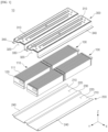
FIG. 1 is an exploded perspective view of a battery module according to example embodiments of the present invention. -
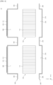
FIG. 2 is a plan view of a battery module according to example embodiments of the present invention. -
FIG. 3 is a cross-sectional view of a battery module according to example embodiments of the present invention. -
FIG. 4 is an exploded view of a battery module according to example embodiments of the present invention. -
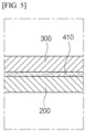
FIG. 5 is a cross-sectional view of a bonding region between an upper case and a lower case of a battery module according to embodiments of the present invention. -
FIG. 6 is a cross-sectional view of a battery module according to example embodiments of the present invention. -
FIG. 7 is a cross-sectional view of a battery pack according to example embodiments of the present invention. -
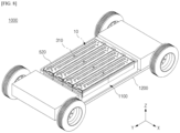
FIG. 8 is a schematic view of an electric vehicle in which a battery pack according to example embodiments of the present invention is mounted. - Hereinafter, embodiments of the present invention will be described in detail with reference to the accompanying drawings. Before describing embodiments of the present invention, the terms or expressions used in the present specification and claims should not be construed as being limited to as generally understood or as defined in commonly used dictionaries, and should be understood according to meanings and concepts corresponding to the present invention on the basis of the principle that the inventor(s) of the application can appropriately define the terms or expressions to optimally explain the present invention.
- Therefore, embodiments set forth herein and configurations illustrated in the drawings are only examples of the present invention and do not reflect all the technical ideas of the present invention and thus it should be understood that various equivalents and modifications that replace the configurations would have been made at the filing date of the present application.
- Well-known configurations or functions related to describing the present invention are not described in detail when it is determined that they would obscure the subject matter of the present invention due to unnecessary detail.
- Because embodiments of the present invention are provided to more fully explain the present invention to those of ordinary skill in the art, the shapes, sizes, etc. of components illustrated in the drawings may be exaggerated, omitted, or schematically illustrated for clarity. Therefore, it should not be understood that the sizes or proportions of components fully reflect the actual sizes or proportions thereof.
-
FIGS. 1 to 5 are diagrams illustrating abattery module 10 according to example embodiments of the present invention.FIG. 1 is an exploded perspective view of thebattery module 10.FIG. 2 is a plan view of thebattery module 10.FIG. 3 is a cross-sectional view of thebattery module 10.FIG. 4 is an exploded view of thebattery module 10.FIG. 5 is a cross-sectional view of a bonding region between anupper case 300 and alower case 200 of thebattery module 10. - Referring to
FIGS. 1 to 5 , thebattery module 10 may include a plurality ofbattery cell assemblies 100, alower case 200, and anupper case 300. - The plurality of
battery cell assemblies 100 may be arranged in a first direction (an X-axis direction). The plurality ofbattery cell assemblies 100 may be spaced from each other in the first direction (the X-axis direction). Although an example in which thebattery module 10 includes twobattery cell assemblies 100 is illustrated, the number ofbattery cell assemblies 100 included in thebattery module 10 is not limited to two. For example, thebattery module 10 may include two or morebattery cell assemblies 100. - Each of the
battery cell assemblies 100 may include acell block 110. Thecell block 110 may include a plurality ofbattery cells 111. Each of thebattery cells 111 is a basic unit of a lithium ion battery, i.e., a secondary battery. Each of thebattery cells 111 may include an electrode assembly, an electrolyte, and a cell case. The electrode assembly provided in the cell case may include a positive electrode, a negative electrode, and a separator between the positive electrode and the negative electrode. The electrode assembly may be a jelly-roll type electrode assembly or a stack type electrode assembly according to a form of assembly. The jelly-roll type electrode assembly may include a structure in which a positive electrode, a negative electrode, and a separator between the positive and negative electrodes are wound together. The stack type electrode assembly may include a plurality of positive electrodes and a plurality of negative electrodes that are sequentially stacked, and a plurality of separators therebetween. The positive electrode may include a positive electrode current collector and a positive electrode active material. The negative electrode may include a negative electrode current collector and a negative electrode active material. - The plurality of
battery cells 111 may be connected in series and/or in parallel. For example, the plurality ofbattery cells 111 may be connected to each other in series. For example, the plurality ofbattery cells 111 may be connected to each other in parallel. For example, when a set of two ormore battery cells 111 connected in parallel is defined as a bank, one bank including two ormore battery cells 111 connected in parallel and another bank including two ormore battery cells 111 connected in parallel may be connected in series. - Each of the
battery cells 111 may be a pouch type battery cell, a cylindrical battery cell, or a prismatic battery cell. An electrode assembly of the pouch type battery cell is embedded in a pouch case including an aluminum laminate sheet. An electrode assembly of the cylindrical battery cell is embedded in a cylindrical metal can. An electrode assembly of the prismatic battery cell is embedded in a prismatic metal can. - In example embodiments, the
battery cells 111 may be pouch type battery cells and be stacked together in onebattery cell assembly 100 in the first direction (the X-axis direction). In example embodiments, in eachbattery cell assembly 100, the plurality ofbattery cells 111 may be pouch type battery cells whose length in the first direction (the X-axis direction) is less than a length thereof in a second direction (a Y-axis direction) and be stacked in the first direction (the X-axis direction). - When viewed in a plan view, the
cell block 110 may have a rectangular shape whose length in the first direction (the X-axis direction) is less than a length thereof in the second direction (the Y-axis direction). Thecell block 110 may have a first side surface and a second side surface that face each other in the first direction (the X-axis direction), a front surface and a rear surface that face each other in the second direction (the Y-axis direction), and an upper surface and a lower surface that face each other in a third direction (a Z-axis direction). - A bus bar frame on which bus bars are mounted may be on each of the front and rear surfaces of the
cell block 110. A plurality of bus bars may be mounted on the bus bar frame on the front surface of thecell block 110, and a plurality of bus bars may be mounted on the bus bar frame on the rear surface of thecell block 110. Thebattery cell assembly 100 may include anend plate 120 to cover a bus bar frame connected to the front or rear surface of thecell block 110. - A bus bar may be coupled to an electrode lead of the
battery cell 111. For example, the bus bar may be coupled to the electrode lead of thebattery cell 111 by welding. For example, each bus bar may be an inter-bus bar coupled to electrode leads connected todifferent battery cells 111 belonging to thecell block 110 to electrically connect thedifferent battery cells 111. For example, each bus bar may be a terminal bus bar for electrically coupling thebattery cell assembly 100 to another externalbattery cell assembly 100 or another electrical device. - The
battery cell assembly 100 may include a plurality of cell blocks 110. For example, as shown inFIG. 1 , each of thebattery cell assemblies 100 may include twocell blocks 110 arranged in the second direction (the Y-axis direction) to be electrically connected to each other. - The
lower case 200 may support the plurality ofbattery cell assemblies 100. Thelower case 200 may include a plurality oflower accommodation spaces 220 for accommodation of the plurality ofbattery cell assemblies 100. Each of thelower accommodation spaces 220 may accommodate a lower part of a correspondingbattery cell assembly 100 among the plurality ofbattery cell assemblies 100. The number of thelower accommodation spaces 220 of thelower case 200 may be the same as the number of thebattery cell assemblies 100. In example embodiments, thelower case 200 may be a single piece and an overall material composition thereof may be the same. For example, in order to manufacture thelower case 200, a single flat plate may be prepared and press processing may be performed on the single flat plate to cause the single flat plate to have a predetermined structure. - The
lower case 200 may include a plurality offirst pocket parts 210, afirst connection part 230, and afirst flange 240. The plurality offirst pocket parts 210, thefirst connection part 230, and thefirst flange 240 may be formed in one body. - The plurality of
first pocket parts 210 may be spaced apart from each other in the first direction (the X-axis direction). Each of thefirst pocket parts 210 may include alower accommodation space 220 for accommodation of the lower part of thebattery cell assembly 100 corresponding thereto. Each of thefirst pocket parts 210 may have a U-shape when viewed in a cross-sectional view. Each of thefirst pocket parts 210 may include a bottom wall facing the lower surface of the correspondingbattery cell assembly 100, and two lower side walls spaced apart from each other in the first direction (the X-axis direction) with the correspondingbattery cell assembly 100 therebetween. One of the two lower side walls may continuously extend along a first edge of the bottom wall, and the other lower side wall may continuously extend along a second edge opposite the first edge of the bottom wall. When viewed in a plan view, the bottom wall may have a tetragonal shape. In each of thefirst pocket parts 210, thelower accommodation space 220 may be defined by the bottom wall and the two lower side walls. A length of thelower accommodation space 220 in the first direction (the X-axis direction) may be equal to a length of the bottom wall in the first direction (the X-axis direction), a length of thelower accommodation space 220 in the second direction (the Y-axis direction) may be equal to a length of the bottom wall in the second direction (the Y-axis direction), and a length (or depth) of thelower accommodation space 220 in the third direction (the Z-axis direction) may be equal to a length of the lower side walls in the third direction (the Z-axis direction). - The
first connection part 230 may extend between twofirst pocket parts 210 that are adj acent to each other in the first direction (the X-axis direction) among the plurality offirst pocket parts 210. For example, thefirst connection part 230 may extend from an upper end of one of the twofirst pocket parts 210 to an upper end of the othersecond pocket part 310 to physically connect the twofirst pocket parts 210. Thefirst connection part 230 may have a tetragonal flat plate shape. Thefirst connection part 230 may have a tetragonal shape when viewed in a plan view, and an upper surface of thefirst connection part 230 may be flat. Thefirst connection part 230 may continuously extend from one end of thefirst pocket part 210 to another end of thefirst pocket part 210 in the second direction (the Y-axis direction), and a length of thefirst connection part 230 in the second direction (the Y-axis direction) may be the same or substantially the same as a length of thefirst pocket part 210 in the second direction (the Y-axis direction). - The
first flange 240 may be connected to an outermostfirst pocket part 210 among the plurality offirst pocket parts 210. For example, thelower case 200 may include onefirst flange 240 extending outward from a leftmostfirst pocket part 210 among the plurality offirst pocket parts 210, and onefirst flange 240 extending outward from a rightmostfirst pocket part 210 among the plurality offirst pocket parts 210. Thefirst flange 240 may continuously extend in the second direction (the Y-axis direction) along an edge of afirst pocket part 210 corresponding thereto. Thefirst flange 240 may have a tetragonal flat plate shape. Thefirst flange 240 may have a tetragonal shape when viewed in a plan view, and an upper surface of thefirst flange 240 may be flat. Thefirst flange 240 may continuously extend from one end of thefirst pocket part 210 to another end of thefirst pocket part 210 in the second direction (the Y-axis direction), and a length of thefirst flange 240 in the second direction (the Y-axis direction) may be the same or substantially the same as a length of thefirst pocket part 210 in the second direction (the Y-axis direction). - The
upper case 300 may be on thelower case 200. Theupper case 300 may be coupled to thelower case 200 to cover a plurality ofbattery cell assemblies 100 on thelower case 200. Theupper case 300 may include a plurality ofupper accommodation spaces 320 for accommodation of the plurality ofbattery cell assemblies 100. Each of theupper accommodation spaces 320 may accommodate an upper part of a correspondingbattery cell assembly 100 among the plurality ofbattery cell assemblies 100. The number of theupper accommodation spaces 320 of theupper case 300 may be the same as the number ofbattery cell assemblies 100, and the position of each of theupper accommodation spaces 320 may vertically overlap a correspondinglower accommodation space 220 among the plurality oflower accommodation spaces 220. In example embodiments, theupper case 300 may be a single piece and an overall material composition thereof may be the same. For example, in order to manufacture theupper case 300, a single flat plate may be prepared and press processing may be performed on the single flat plate to cause the single flat plate to have a predetermined structure. - The
upper case 300 may include a plurality ofsecond pocket parts 310, asecond connection part 330, and asecond flange 340. The plurality ofsecond pocket parts 310, thesecond connection part 330, and thesecond flange 340 may be formed in one body. - The plurality of
second pocket parts 310 may be spaced apart from each other in the first direction (the X-axis direction). Each of thesecond pocket parts 310 may include anupper accommodation space 320 for accommodation of the upper part of thebattery cell assembly 100 corresponding thereto. Each of thesecond pocket parts 310 may include an upper wall facing the upper surface of the correspondingbattery cell assembly 100, and two upper side walls spaced apart from each other in the first direction (the X-axis direction) with the correspondingbattery cell assembly 100 therebetween. One of the two upper side walls may continuously extend along a first edge of the upper wall, and the other upper side wall may continuously extend along a second edge opposite the first edge of the upper wall. When viewed in a plan view, the upper wall may have a tetragonal shape. In each of thesecond pocket parts 310, theupper accommodation space 320 may be defined by the upper wall and the two upper side walls. A length of theupper accommodation space 320 in the first direction (the X-axis direction) may be equal to a length of the upper wall in the first direction (the X-axis direction), a length of theupper accommodation space 320 in the second direction (the Y-axis direction) may be equal to a length of the upper wall in the second direction (the Y-axis direction), and a length (or depth) of theupper accommodation space 320 in the third direction (the Z-axis direction) may be equal to a length of the upper side walls in the third direction (the Z-axis direction). - The
second connection part 330 may extend between twosecond pocket parts 310 that are adjacent to each other in the first direction (the X-axis direction) among the plurality ofsecond pocket parts 310. For example, thesecond connection part 330 may extend from a lower end of one of the twosecond pocket parts 310 to a lower end of the othersecond pocket part 310 to physically connect the twosecond pocket parts 310. Thesecond connection part 330 may have a tetragonal flat plate shape. Thesecond connection part 330 may have a tetragonal shape when viewed in a plan view, and a lower surface of thesecond connection part 330 may be flat. Thesecond connection part 330 may continuously extend from one end of thesecond pocket part 310 to another end of thesecond pocket part 310 in the second direction (the Y-axis direction), and a length of thesecond connection part 330 in the second direction (the Y-axis direction) may be the same or substantially the same as a length of thesecond pocket part 310 in the second direction (the Y-axis direction). A lower surface of thesecond connection part 330 may be in surface contact with the upper surface of thefirst connection part 230. Thefirst connection part 230 and thefirst connection part 230 may be in continuous or discontinuous contact with each other in the second direction (the Y-axis direction). Thesecond connection part 330 may be coupled to thefirst connection part 230. Thesecond connection part 330 may be coupled to thefirst connection part 230 to couple theupper case 300 to thelower case 200. - The
second flange 340 may be connected to an outermostsecond pocket part 310 among the plurality ofsecond pocket parts 310. For example, theupper case 300 may include onesecond flange 340 extending outward from a leftmostsecond pocket part 310 among the plurality ofsecond pocket parts 310, and onesecond flange 340 extending outward from a rightmostsecond pocket part 310 among the plurality ofsecond pocket parts 310. Thesecond flange 340 may continuously extend in the second direction (the Y-axis direction) along an edge of thesecond pocket part 310 corresponding thereto. Thesecond flange 340 may have a tetragonal flat plate shape. Thesecond flange 340 may have a tetragonal shape when viewed in a plan view, and a lower surface of thesecond flange 340 may be flat. Thesecond flange 340 may continuously extend from one end of thesecond pocket part 310 to another end of thesecond pocket part 310 in the second direction (the Y-axis direction), and a length of thesecond flange 340 in the second direction (the Y-axis direction) may be the same or substantially the same as the length of thesecond pocket part 310 in the second direction (the Y-axis direction). Thesecond flange 340 and thefirst flange 240 may be in continuous or discontinuous contact with each other in the second direction (the Y-axis direction). A lower surface of thesecond flange 340 may be in surface contact with the upper surface of thefirst flange 240. Thesecond flange 340 may be coupled to thefirst flange 240. Thesecond flange 340 may be coupled to thefirst flange 240 to couple theupper case 300 to thelower case 200. - In example embodiments, the
lower case 200 and theupper case 300 may be coupled to each other by welding. As shown inFIG. 5 , abonding layer 410, for example, a metal bonding layer containing a metal may be interposed between thelower case 200 and theupper case 300. The metal bonding layer may be a material layer formed by welding. In example embodiments, thebonding layer 410 may be interposed between the upper surface of thefirst connection part 230 of thelower case 200 and the lower surface of thesecond connection part 330 of theupper case 300, and thefirst connection part 230 may be bonded to thesecond connection part 330 by thebonding layer 410. At an interface between thefirst connection part 230 and thesecond connection part 330, thebonding layer 410 may extend continuously or discontinuously along the second direction (the Y-axis direction). In example embodiments, thebonding layer 410 may be interposed between the upper surface of thefirst flange 240 of thelower case 200 and the lower surface of thesecond flange 340 of theupper case 300, and thefirst flange 240 may be bonded to thesecond flange 340 by thebonding layer 410. At an interface between thefirst flange 240 and thesecond flange 340, thebonding layer 410 may extend continuously or discontinuously along the second direction (the Y-axis direction). - In example embodiments, the
upper case 300 may include acooling channel 311 configured to allow a cooling fluid to flow therethrough, and be configured to cool thebattery cell assembly 100 so that thebattery cell assembly 100 may have an appropriate operating temperature. The coolingchannel 311 may be provided in each of the plurality ofsecond pocket parts 310 of theupper case 300. For example, the coolingchannel 311 may be provided in an upper wall and/or an upper side wall of each of thesecond pocket parts 310. The cooling fluid provided from the outside may flow into the coolingchannel 311 through an inlet of thecooling channel 311, flow along the coolingchannel 311, and be discharged to the outside through an outlet of thecooling channel 311. While the cooling fluid flows along the coolingchannel 311, thebattery cell assembly 100 may be cooled. In example embodiments, a thermally conductive adhesive layer may be interposed between theupper case 300 and thebattery cell assembly 100 to improve thermal coupling between theupper case 300 and thebattery cell assembly 100. The thermally conductive adhesive layer may include, for example, a thermal interface material (TIM). In this case, heat generated in thebattery cell assembly 100 may be transferred to theupper case 300 through the thermally conductive adhesive layer. - According to example embodiments of the present invention, each of the
upper case 300 and thelower case 200, which are structures for accommodating and supporting the plurality ofbattery cell assemblies 100, is configured as an integrated press product to simplify a manufacturing process of thebattery module 10 and reduce manufacturing costs of thebattery module 10. Because the plurality ofbattery cell assemblies 100 may be accommodated in the accommodation spaces provided by theupper case 300 and thelower case 200, thebattery module 10 may be manufactured on a large scale. - In addition, according to example embodiments of the present invention, a bonding area between the
lower case 200 and theupper case 300 is relatively large and thus a wide weldable area may be secured when a welding process is performed to couple thelower case 200 and theupper case 300. Accordingly, the manufacturing process of thebattery module 10 may be facilitated. -
FIG. 6 is a cross-sectional view of abattery module 10A according to example embodiments of the present invention. Hereinafter, thebattery module 10A ofFIG. 6 will be described focusing on differences from thebattery module 10 described above with reference toFIGS. 1 to 5 . - Referring to
FIG. 6 , in thebattery module 10A, alower case 200 may include acooling channel 211 configured to allow a cooling fluid to flow therethrough, and be configured to cool abattery cell assembly 100 so that thebattery cell assembly 100 may have an appropriate operating temperature. The coolingchannel 211 may be provided in each of a plurality offirst pocket parts 210 of thelower case 200. For example, the coolingchannel 211 may be provided in a lower wall and/or a lower side wall of each of thefirst pocket parts 210. The cooling fluid provided from the outside may flow into the coolingchannel 211 through an inlet of thecooling channel 211, flow along the coolingchannel 211, and be discharged to the outside through an outlet of thecooling channel 211. In example embodiments, a thermally conductive adhesive layer including a material such as the TIM may be interposed between thelower case 200 and thebattery cell assembly 100 to improve thermal coupling between thelower case 200 and thebattery cell assembly 100. - In example embodiments, both an
upper case 300 and thelower case 200 may include thecooling channel 211. That is, theupper case 300 may include acooling channel 311 therein as illustrated inFIG. 3 , and thelower case 200 may include thecooling channel 211 as illustrated inFIG. 6 . -
FIG. 7 is a cross-sectional view of abattery pack 500 according to example embodiments of the present invention. - Referring to
FIG. 7 , thebattery pack 500 may include apack housing 501 and abattery module 10 on thepack housing 501. Thebattery pack 500 may include one ormore battery modules 10 on thepack housing 501. AlthoughFIG. 7 illustrates that thebattery pack 500 includes thebattery module 10 described above with reference toFIGS. 1 to 5 , embodiments are not limited thereto and thebattery pack 500 may include thebattery module 10A described above with reference toFIG. 6 . - The
pack housing 501 may include alower housing 510 with an accommodation space for accommodation of thebattery module 10, and apack lid 520 coupled to thelower housing 510 to cover thelower housing 510 in which thebattery module 10 is accommodated. The accommodation space of thelower housing 510 may be defined by abottom plate 511 facing a lower surface of thebattery module 10 andside walls 513 on edges of thebottom plate 511. A plurality ofsupport structures 515 may be provided on thebottom plate 511 of thelower housing 510 to support thebattery module 10. The plurality ofsupport structures 515 may be spaced apart from each other in the first direction (the X-axis direction) and each extend in the second direction (the Y-axis direction). A length of each of thesupport structures 515 in the second direction (the Y-axis direction) may be equal to or greater than a length of thebattery module 10 in the second direction (the Y-axis direction). - The
battery module 10 may be mounted in thepack housing 501 in a side mounting manner. The plurality ofsupport structures 515 each extending in the second direction (the Y-axis direction) may be provided on thebottom plate 511 of thepack housing 501, and thebattery module 10 may be fastened to the plurality ofsupport structures 515 by a fastening member such as a bolt BT. - More specifically, a
first connection part 230 of alower case 200 and asecond connection part 330 of anupper case 300 may be combined to form a first assembly, and the first assembly may be disposed on acorresponding support structure 515 among the plurality ofsupport structures 515 and fastened to thecorresponding support structure 515 by the bolt BT. Thesupport structure 515 may be in continuous contact with the first assembly in the second direction (the Y-axis direction). Because a contact area between thesupport structure 515 and the first assembly may be relatively large, thebattery module 10 may be stably supported by thesupport structure 515. - In addition, a
first flange 240 of thelower case 200 and asecond flange 340 of theupper case 300 may be combined to form a second assembly, and the second assembly may be disposed on acorresponding support structure 515 among the plurality ofsupport structures 515 and fastened to thecorresponding support structure 515 by the bolt BT. Thesupport structure 515 may be in continuous contact with the second assembly in the second direction (the Y-axis direction). Because a contact area between thesupport structure 515 and the second assembly may be relatively large, thebattery module 10 may be stably supported by thesupport structure 515. - When the
battery pack 500 is mounted in a vehicle, a cabin room in which a passenger rides may be located above thepack lid 520, and the ground on which the vehicle travels may be located below thelower housing 510. - The
battery module 10 may be supported by thesupport structure 515 on thebottom plate 511 of thelower housing 510 in the side mounting method, and a free volume FV may be formed between thebottom plate 511 of thelower housing 510 and thebattery module 10 as thebottom plate 511 of thelower housing 510 and thebattery module 10 are spaced apart from each other in the third direction (the Z-axis direction). A gas and flames generated in a thermal runaway situation may move through the free volume FV. That is, the free volume FV functions as a venting passage through which a high-temperature gas and flames may move. - Even when strong impact is generated due to a foreign material splashing to a lower part of a vehicle when driving on a hard ground such as a non-paved road, the impact may be absorbed through the free volume FV. Therefore, the
battery module 10 may be prevented from being damaged due to the impact. The free volume FV may be understood as an empty space between thebattery module 10 and thelower housing 510. When thelower housing 510 is deformed toward thebattery module 10 due to an impact applied to the lower part of the vehicle, the free volume FV may freely allow deformation of thelower housing 510 to some extent. - A height of the free volume FV and a distance between the
bottom plate 511 of thelower housing 510 and thebattery module 10 may be determined enough to absorb external impact. The height of the free volume FV may be determined in consideration of dimensions and rigidity of frames of the vehicle, dimensions and rigidity of thelower housing 510, dimensions of thebattery pack 500, the amount of a generated gas and a gas discharge rate during thermal runaway, and the like. For example, when a thickness or rigidity of the frames of the vehicle or thebottom plate 511 of thelower housing 510 is relatively large, at least one of the size and height of the free volume FV may be relatively reduced. When the thickness or rigidity of the frames of the vehicle or thebottom plate 511 of thelower housing 510 is relatively small, thebottom plate 511 of thelower housing 510 is highly likely to deform and thus at least one of the size and height of the free volume FV may be relatively increased to protect thebattery module 10. When the size of thebattery pack 500 is relatively large compared to the specifications of thebattery pack 500, a relatively large free volume FV may be secured. When the size of thebattery pack 500 is relatively small, a height of the free volume FV to be secured may be relatively small and thus the thickness and rigidity of thebottom plate 511 of thelower housing 510 may be relatively increased. When the height of the free volume FV is extremely small, a gas discharge passage may be small and thus internal pressure of thebattery pack 500 may increase sharply during thermal runaway. Accordingly, the size and height of the free volume FV may be determined in consideration of the amount of a generated gas and a gas discharge rate. - A maximum height of the free volume FV may be determined according to a damage tolerance of the
battery cell 111 included in thebattery module 10. For example, when the damage tolerance of thebattery cell 111 is 1 mm, the free volume FV may be determined to prevent thebattery cell 111 from deforming by more than 1 mm when thelower housing 510 deforms and pressurizes a lower surface of thebattery cell 111. In this case, a degree of deformation of thelower housing 510 may vary according to the thickness or rigidity of thelower housing 510. Therefore, the size or height of the free volume FV may be determined in consideration of all the damage tolerance of thebattery cell 111 and the thickness and rigidity of thelower housing 510. - In example embodiments, an upper surface of the
battery module 10 may be in close contact with a lower side of thepack lid 520. In example embodiments, thebattery module 10 may be supported while being hung from thepack lid 520. When there is a space between thebattery modules 10 and thepack lid 520, a high-temperature gas may flow into the space between one of thebattery modules 10 and thepack lid 520 during thermal runaway and heat and flames may propagate toadjacent battery modules 10 and also be transferred to thepack lid 520, and thus, the cabin room above thepack lid 520 may be influenced by the heat and the flames. Therefore, a gas or flames generated in thebattery pack 500 may be guided to the free volume FV by bringing the upper surface of thebattery module 10 and the lower surface of thepack lid 520 into close contact with each other. - According to example embodiments of the present invention, a contact area between the
battery module 10 and thesupport structure 515 of thepack housing 501 is relatively large to disperse stress applied to coupling portions of thebattery module 10 and thepack housing 501 and reduce damage to the coupling portions of thebattery module 10 and thepack housing 501. Accordingly, the safety and reliability of thebattery pack 500 may improve. -
FIG. 8 is a schematic view of anelectric vehicle 1000 in which abattery pack 1100 according to example embodiments of the present invention is mounted. - For the sake of simplicity,
FIG. 8 illustrates only avehicle body frame 1200 forming a lower frame of theelectric vehicle 1000, and thebattery pack 1100 and tires that are coupled to thevehicle body frame 1200. Thebattery pack 1100 may include thebattery pack 500 described above with reference toFIG. 7 . - In the case of a general battery pack, a battery module is installed at the bottom of a pack housing of the battery pack. In embodiments, the free volume FV (see
FIG. 7 ) may be provided below thebattery module 10 of thebattery pack 1100, and there may be no space or a very narrow space between thebattery module 10 and thepack lid 520. Accordingly, a gas generated in thebattery module 10 may be prevented from being transferred to the cabin room corresponding to an upper part of the vehicle and be guided to the free volume FV between thebattery module 10 and thepack housing 501 of thebattery pack 1100. The gas may flow through the free volume FV to be discharged to a lower side of theelectric vehicle 1000 through a gas exhaust installed in thebattery pack 1100. In addition, according to the present embodiments, in thebattery pack 1100, the free volume FV is provided between thebattery module 10 and the pack housing to prevent thebattery module 10 from being damaged regardless of the deformation of thepack housing 501. - According to embodiments of the present invention, the
battery pack 1100 and theelectric vehicle 1000 including the same are capable of increasing the safety of passengers. In addition, thebattery module 10 that is a key component can be protected and the durabilities of thebattery pack 1100 and theelectric vehicle 1000 can be enhanced. - The present invention has been described above in more detail with reference to the drawings, the embodiments, etc. However, the configurations illustrated in the drawings or embodiments described in the present specification are only embodiments of the present invention and do not reflect all the technical ideas of the present invention and thus it should be understood that various equivalents and modifications that replace the configurations would have been made at the filing date of the present application.
Claims (15)
- A battery module comprising:a plurality of battery cell assemblies each including a plurality of battery cells;a lower case including a plurality of first pocket parts spaced apart from each other in a first direction and a first connection part extending between two adjacent first pocket parts among the plurality of first pocket parts, wherein each of the plurality of first pocket parts includes a lower accommodation space for accommodation of a lower part of a corresponding battery cell assembly among the plurality of battery cell assemblies and the plurality of first pocket parts and the first connection part are integrally formed; andan upper case including a plurality of second pocket parts spaced apart from each other in the first direction and a second connection part extending between two adjacent second pocket parts among the plurality of second pocket parts, wherein each of the plurality of second pocket parts includes an upper accommodation space for accommodation of an upper part of a corresponding battery cell assembly among the plurality of battery cell assemblies and the plurality of second pocket parts and the second connection part are integrally formed,wherein the lower case and the upper case are coupled to each other by coupling the first connection part and the second connection part.
- The battery module of claim 1, whereinthe first connection part extends from one end of each of the first pocket parts to another end of each of the first pocket parts in a second direction crossing the first direction, andthe second connection part extends from one end of each of the second pocket parts to another end of each of the second pocket parts in the second direction.
- The battery module of claim 2, whereinthe first connection part includes a flat upper surface,the second connection part includes a flat lower surface, andthe upper surface of the first connection part is in contact with the lower surface of the second connection part.
- The battery module of claim 1, further comprising
a bonding layer between the first connection part and the second connection part. - The battery module of claim 4, wherein
the bonding layer includes a metal. - The battery module of claim 1, whereinthe lower case further includes a first flange extending from an outermost first pocket part among the plurality of first pocket parts,the upper case further includes a second flange extending from an outermost second pocket part among the plurality of second pocket parts, andthe first flange is coupled to the second flange.
- The battery module of claim 6, whereinthe first flange extends from one end of the outermost first pocket part to another end of the outermost first pocket part in a second direction crossing the first direction,the second flange extends from one end of the outermost second pocket part to another end of the outermost second pocket part in the second direction,the first flange includes a flat upper surface,the second flange includes a flat lower surface, andthe upper surface of the first flange is in contact with the lower surface of the second flange.
- The battery module of claim 6, wherein
the first flange and the second flange are coupled to each other by a metal bonding layer. - The battery module of claim 1, wherein
each of the plurality of first pocket parts includes a first cooling channel. - The battery module of claim 1, wherein
each of the plurality of second pocket parts includes a second cooling channel. - The battery module of claim 1, wherein,
in each of the plurality of battery cell assemblies, the plurality of battery cells are stacked in the first direction. - A battery pack comprising:a pack housing; anda battery module in the pack housing,wherein the battery module includes:a plurality of battery cell assemblies each including a plurality of battery cells;a lower case including a plurality of first pocket parts spaced apart from each other in a first direction and a first connection part extending between two adjacent first pocket parts among the plurality of first pocket parts, wherein each of the plurality of first pocket parts includes a lower accommodation space for accommodation of a lower part of a corresponding battery cell assembly among the plurality of battery cell assemblies and the plurality of first pocket parts and the first connection part are integrally formed; andan upper case including a plurality of second pocket parts spaced apart from each other in the first direction and a second connection part extending between two adjacent second pocket parts among the plurality of second pocket parts, wherein each of the plurality of second pocket parts includes an upper accommodation space for accommodation of an upper part of a corresponding battery cell assembly among the plurality of battery cell assemblies and the plurality of second pocket parts and the second connection part are integrally formed,wherein the lower case and the upper case are coupled to each other by coupling the first connection part and the second connection part.
- The battery pack of claim 12, whereinthe battery module is spaced apart from a bottom plate of the pack housing, anda space is provided between the battery module and the bottom plate of the pack housing.
- The battery pack of claim 12, wherein
the pack housing includes a support structure configured to support an assembly of the first connection part and the second connection part. - The battery pack of claim 12, whereinthe lower case further includes a first flange extending from an outermost first pocket part among the plurality of first pocket parts,the upper case further includes a second flange extending from an outermost second pocket part among the plurality of second pocket parts,the first flange is coupled to the second flange, andthe pack housing includes a support structure configured to support an assembly of the first flange and the second flange.
Applications Claiming Priority (2)
| Application Number | Priority Date | Filing Date | Title |
|---|---|---|---|
| KR1020230101567A KR102953646B1 (en) | 2023-08-03 | 2023-08-03 | Battery module and battery pack including the same |
| PCT/KR2024/010994 WO2025028966A1 (en) | 2023-08-03 | 2024-07-29 | Battery module and battery pack comprising same |
Publications (2)
| Publication Number | Publication Date |
|---|---|
| EP4583284A1 true EP4583284A1 (en) | 2025-07-09 |
| EP4583284A4 EP4583284A4 (en) | 2026-04-08 |
Family
ID=94395544
Family Applications (1)
| Application Number | Title | Priority Date | Filing Date |
|---|---|---|---|
| EP24849535.0A Pending EP4583284A4 (en) | 2023-08-03 | 2024-07-29 | BATTERY MODULE AND BATTERY PACK SO THAT |
Country Status (5)
| Country | Link |
|---|---|
| EP (1) | EP4583284A4 (en) |
| JP (1) | JP2025533292A (en) |
| KR (1) | KR102953646B1 (en) |
| CN (1) | CN120051892A (en) |
| WO (1) | WO2025028966A1 (en) |
Families Citing this family (1)
| Publication number | Priority date | Publication date | Assignee | Title |
|---|---|---|---|---|
| KR102867142B1 (en) * | 2025-05-27 | 2025-10-01 | 주식회사 서연이화 | Cooling system of battery module |
Family Cites Families (11)
| Publication number | Priority date | Publication date | Assignee | Title |
|---|---|---|---|---|
| JP5443039B2 (en) * | 2009-04-07 | 2014-03-19 | アイシン軽金属株式会社 | Battery stack fixing structure |
| KR101749190B1 (en) * | 2013-05-29 | 2017-07-03 | 삼성에스디아이 주식회사 | Battery module |
| JP2016033914A (en) * | 2014-07-29 | 2016-03-10 | 株式会社豊田自動織機 | Power storage device |
| KR102072220B1 (en) * | 2016-01-12 | 2020-01-31 | 주식회사 엘지화학 | Battery Pack Capable of Minimizing Space for Mounting to Device |
| CN110235274A (en) | 2016-12-05 | 2019-09-13 | 三星Sdi株式会社 | Removable battery component carrier, the battery system including removable battery component carrier and including the vehicle of battery system |
| MX2020007957A (en) * | 2018-01-31 | 2021-07-02 | Tpi Composites Inc | A composite battery enclosure. |
| DE102018106399A1 (en) * | 2018-03-19 | 2019-09-19 | Muhr Und Bender Kg | Housing arrangement for receiving electrical storage means and method for producing a housing assembly |
| KR102917117B1 (en) * | 2020-11-05 | 2026-01-22 | 주식회사 엘지에너지솔루션 | Battery module and battery pack including the same |
| CN113410546A (en) * | 2021-06-18 | 2021-09-17 | 恒大新能源技术(深圳)有限公司 | Battery module and battery pack |
| KR102657678B1 (en) | 2021-12-17 | 2024-04-17 | 서진산업 주식회사 | Electric vehicle block type multi-battery supply device |
| KR102708757B1 (en) | 2021-12-29 | 2024-09-23 | 재단법인 대구경북첨단의료산업진흥재단 | Body organ model apparatus for urodynamic study apparatus |
-
2023
- 2023-08-03 KR KR1020230101567A patent/KR102953646B1/en active Active
-
2024
- 2024-07-29 CN CN202480004382.7A patent/CN120051892A/en active Pending
- 2024-07-29 WO PCT/KR2024/010994 patent/WO2025028966A1/en active Pending
- 2024-07-29 JP JP2025521379A patent/JP2025533292A/en active Pending
- 2024-07-29 EP EP24849535.0A patent/EP4583284A4/en active Pending
Also Published As
| Publication number | Publication date |
|---|---|
| KR20250020103A (en) | 2025-02-11 |
| KR102953646B1 (en) | 2026-04-15 |
| EP4583284A4 (en) | 2026-04-08 |
| WO2025028966A1 (en) | 2025-02-06 |
| JP2025533292A (en) | 2025-10-03 |
| CN120051892A (en) | 2025-05-27 |
Similar Documents
| Publication | Publication Date | Title |
|---|---|---|
| EP4611128A1 (en) | Battery cell assembly and battery pack comprising same | |
| JP2025533292A (en) | Battery module and battery pack including same | |
| EP4742403A1 (en) | Battery pack comprising battery assembly, and electric vehicle comprising battery pack | |
| EP4614680A1 (en) | Battery cell assembly and battery pack comprising same | |
| EP4614679A1 (en) | Battery assembly and battery pack comprising same | |
| EP4614702A1 (en) | Battery pack | |
| EP4586368A1 (en) | Battery cell assembly and battery pack including same | |
| EP4525143B1 (en) | Battery cell assembly and battery pack including the same | |
| EP4664646A1 (en) | Battery assembly | |
| EP4675766A1 (en) | Battery pack | |
| EP4621962A1 (en) | Battery pack | |
| KR102886360B1 (en) | Battery pack including battery assembly and electric vehicle including battery pack | |
| US20250070353A1 (en) | Battery cell assembly and battery pack including the same | |
| KR102872687B1 (en) | Battery pack | |
| EP4712235A1 (en) | Battery assembly and battery pack comprising same | |
| EP4708461A1 (en) | Battery pack | |
| KR20250036471A (en) | Battery assembly and battery pack including the same | |
| CN121058124A (en) | Battery assembly and battery pack including the battery assembly |
Legal Events
| Date | Code | Title | Description |
|---|---|---|---|
| STAA | Information on the status of an ep patent application or granted ep patent |
Free format text: STATUS: THE INTERNATIONAL PUBLICATION HAS BEEN MADE |
|
| PUAI | Public reference made under article 153(3) epc to a published international application that has entered the european phase |
Free format text: ORIGINAL CODE: 0009012 |
|
| STAA | Information on the status of an ep patent application or granted ep patent |
Free format text: STATUS: REQUEST FOR EXAMINATION WAS MADE |
|
| 17P | Request for examination filed |
Effective date: 20250401 |
|
| AK | Designated contracting states |
Kind code of ref document: A1 Designated state(s): AL AT BE BG CH CY CZ DE DK EE ES FI FR GB GR HR HU IE IS IT LI LT LU LV MC ME MK MT NL NO PL PT RO RS SE SI SK SM TR |
|
| A4 | Supplementary search report drawn up and despatched |
Effective date: 20260306 |
|
| RIC1 | Information provided on ipc code assigned before grant |
Ipc: H01M 50/258 20210101AFI20260302BHEP Ipc: H01M 50/211 20210101ALI20260302BHEP Ipc: H01M 10/6556 20140101ALI20260302BHEP Ipc: H01M 10/613 20140101ALI20260302BHEP |