EP4583275A1 - Battery pack - Google Patents
Battery pack Download PDFInfo
- Publication number
- EP4583275A1 EP4583275A1 EP24187078.1A EP24187078A EP4583275A1 EP 4583275 A1 EP4583275 A1 EP 4583275A1 EP 24187078 A EP24187078 A EP 24187078A EP 4583275 A1 EP4583275 A1 EP 4583275A1
- Authority
- EP
- European Patent Office
- Prior art keywords
- battery cells
- holder
- battery
- battery pack
- hook
- Prior art date
- Legal status (The legal status is an assumption and is not a legal conclusion. Google has not performed a legal analysis and makes no representation as to the accuracy of the status listed.)
- Pending
Links
Images





Classifications
-
- H—ELECTRICITY
- H01—ELECTRIC ELEMENTS
- H01M—PROCESSES OR MEANS, e.g. BATTERIES, FOR THE DIRECT CONVERSION OF CHEMICAL ENERGY INTO ELECTRICAL ENERGY
- H01M50/00—Constructional details or processes of manufacture of the non-active parts of electrochemical cells other than fuel cells, e.g. hybrid cells
- H01M50/20—Mountings; Secondary casings or frames; Racks, modules or packs; Suspension devices; Shock absorbers; Transport or carrying devices; Holders
- H01M50/244—Secondary casings; Racks; Suspension devices; Carrying devices; Holders characterised by their mounting method
-
- H—ELECTRICITY
- H01—ELECTRIC ELEMENTS
- H01M—PROCESSES OR MEANS, e.g. BATTERIES, FOR THE DIRECT CONVERSION OF CHEMICAL ENERGY INTO ELECTRICAL ENERGY
- H01M50/00—Constructional details or processes of manufacture of the non-active parts of electrochemical cells other than fuel cells, e.g. hybrid cells
- H01M50/20—Mountings; Secondary casings or frames; Racks, modules or packs; Suspension devices; Shock absorbers; Transport or carrying devices; Holders
- H01M50/204—Racks, modules or packs for multiple batteries or multiple cells
- H01M50/207—Racks, modules or packs for multiple batteries or multiple cells characterised by their shape
- H01M50/213—Racks, modules or packs for multiple batteries or multiple cells characterised by their shape adapted for cells having curved cross-section, e.g. round or elliptic
-
- H—ELECTRICITY
- H01—ELECTRIC ELEMENTS
- H01M—PROCESSES OR MEANS, e.g. BATTERIES, FOR THE DIRECT CONVERSION OF CHEMICAL ENERGY INTO ELECTRICAL ENERGY
- H01M50/00—Constructional details or processes of manufacture of the non-active parts of electrochemical cells other than fuel cells, e.g. hybrid cells
- H01M50/20—Mountings; Secondary casings or frames; Racks, modules or packs; Suspension devices; Shock absorbers; Transport or carrying devices; Holders
- H01M50/289—Mountings; Secondary casings or frames; Racks, modules or packs; Suspension devices; Shock absorbers; Transport or carrying devices; Holders characterised by spacing elements or positioning means within frames, racks or packs
- H01M50/291—Mountings; Secondary casings or frames; Racks, modules or packs; Suspension devices; Shock absorbers; Transport or carrying devices; Holders characterised by spacing elements or positioning means within frames, racks or packs characterised by their shape
-
- H—ELECTRICITY
- H01—ELECTRIC ELEMENTS
- H01M—PROCESSES OR MEANS, e.g. BATTERIES, FOR THE DIRECT CONVERSION OF CHEMICAL ENERGY INTO ELECTRICAL ENERGY
- H01M50/00—Constructional details or processes of manufacture of the non-active parts of electrochemical cells other than fuel cells, e.g. hybrid cells
- H01M50/20—Mountings; Secondary casings or frames; Racks, modules or packs; Suspension devices; Shock absorbers; Transport or carrying devices; Holders
- H01M50/233—Mountings; Secondary casings or frames; Racks, modules or packs; Suspension devices; Shock absorbers; Transport or carrying devices; Holders characterised by physical properties of casings or racks, e.g. dimensions
- H01M50/242—Mountings; Secondary casings or frames; Racks, modules or packs; Suspension devices; Shock absorbers; Transport or carrying devices; Holders characterised by physical properties of casings or racks, e.g. dimensions adapted for protecting batteries against vibrations, collision impact or swelling
-
- H—ELECTRICITY
- H01—ELECTRIC ELEMENTS
- H01M—PROCESSES OR MEANS, e.g. BATTERIES, FOR THE DIRECT CONVERSION OF CHEMICAL ENERGY INTO ELECTRICAL ENERGY
- H01M50/00—Constructional details or processes of manufacture of the non-active parts of electrochemical cells other than fuel cells, e.g. hybrid cells
- H01M50/20—Mountings; Secondary casings or frames; Racks, modules or packs; Suspension devices; Shock absorbers; Transport or carrying devices; Holders
- H01M50/262—Mountings; Secondary casings or frames; Racks, modules or packs; Suspension devices; Shock absorbers; Transport or carrying devices; Holders with fastening means, e.g. locks
- H01M50/264—Mountings; Secondary casings or frames; Racks, modules or packs; Suspension devices; Shock absorbers; Transport or carrying devices; Holders with fastening means, e.g. locks for cells or batteries, e.g. straps, tie rods or peripheral frames
-
- Y—GENERAL TAGGING OF NEW TECHNOLOGICAL DEVELOPMENTS; GENERAL TAGGING OF CROSS-SECTIONAL TECHNOLOGIES SPANNING OVER SEVERAL SECTIONS OF THE IPC; TECHNICAL SUBJECTS COVERED BY FORMER USPC CROSS-REFERENCE ART COLLECTIONS [XRACs] AND DIGESTS
- Y02—TECHNOLOGIES OR APPLICATIONS FOR MITIGATION OR ADAPTATION AGAINST CLIMATE CHANGE
- Y02E—REDUCTION OF GREENHOUSE GAS [GHG] EMISSIONS, RELATED TO ENERGY GENERATION, TRANSMISSION OR DISTRIBUTION
- Y02E60/00—Enabling technologies; Technologies with a potential or indirect contribution to GHG emissions mitigation
- Y02E60/10—Energy storage using batteries
Definitions
- a secondary battery is a chargeable and dischargeable battery, different from a primary battery, which is not designed to be chargeable.
- Low-capacity secondary batteries are used in small portable electronic devices, such as smartphones, feature phones, laptop computers, digital cameras, and camcorders, and high-capacity secondary batteries are used as motor-driving power sources, power-storing batteries, etc., for hybrid vehicles, electric vehicles, etc.
- a secondary battery may generally include an electrode assembly including a cathode and an anode, a case accommodating the electrode assembly, an electrode terminal connected to the electrode assembly, etc.
- a battery pack includes a case holder for fixing a plurality of battery cells in a specific position.
- the case holder fixes the plurality of battery cells at the specific position while accommodating at least some of the plurality of battery cells.
- the case holder not only determines the position of the plurality of battery cells but also protects the plurality of battery cells if an external shock is applied thereto. If a shock is applied to the battery pack, the battery case cushions (or protects) the plurality of battery cells from a shock transfer.
- the case holder that fixes the plurality of battery cells inside the battery case also absorbs the shock.
- a battery pack includes: a plurality of battery cells arranged adjacent to one another in a first direction; and a case holder fixing the plurality of battery cells at a specific position.
- the case holder includes: an upper holder accommodating a portion of the plurality of battery cells in a radial direction of the plurality of battery cells; and a lower holder facing the upper holder with the plurality of battery cells therebetween and supporting the plurality of battery cells in the radial direction of the plurality of battery cells in a sandwich form.
- the radial direction may be orthogonal to the first direction.
- the lower holder and/or the upper holder may comprise wall portions that are adapted to the curvature of the outer surface of the battery cells.
- a parting line separating the upper holder and the lower holder from each other may include a plurality of lines.
- a boundary region between the upper holder and the lower holder can be described by more than one, e.g. two or three, straight lines.
- a first line e.g., a first line describing a first contact area
- a second line e.g., a second line describing a second contact area
- the plurality of lines of the parting line may include a combination of straight lines parallel to the radial direction of the plurality of battery cells.
- a first line among the plurality of lines may be parallel to the first direction
- a second line among the plurality of lines may be a radial direction of the plurality of battery cells, but may form an angle with the first direction.
- the second line forming an angle with the first direction may describe a contact area in an edge region of the upper holder and the lower holder.
- the lower holder may include a fixing hook, or a plurality of fixing hooks (for example, 2n fixing hooks or 2n-2 fixing hooks, where n is the number of battery cells), protruding (for example, from a dividing wall separating two battery cells from each other) toward the upper holder, and the upper holder may include a hook coupling hole, or a number of hook coupling holes corresponding to the number of fixing hooks of the lower holder, through which the fixing hook is fixed (or the fixing hooks are fixed).
- a fixing hook or a plurality of fixing hooks (for example, 2n fixing hooks or 2n-2 fixing hooks, where n is the number of battery cells), protruding (for example, from a dividing wall separating two battery cells from each other) toward the upper holder
- the upper holder may include a hook coupling hole, or a number of hook coupling holes corresponding to the number of fixing hooks of the lower holder, through which the fixing hook is fixed (or the fixing hooks are fixed
- a central line of the fixing hook may be formed eccentrically from a center of the hook coupling hole.
- the central line of the fixing hook may be formed at a bisection point of a line segment connecting centers of adjacent ones of the battery cells.
- the fixing hook (e.g., a base of the fixing hook) may be formed at opposite ends in a longitudinal direction of the plurality of battery cells.
- the fixing hook may be (or be arranged) in a range of 3 mm to 10 mm inside, from an end of the plurality of battery cells, in a second direction.
- the second direction may be perpendicular to the first direction.
- the second direction may be a longitudinal direction of the plurality of battery cells.
- the lower holder may include a separation preventing projection configured to prevent separation of the plurality of battery cells in a longitudinal direction of the plurality of battery cells.
- the separation prevention projection may cover part of the end walls of the battery cells. The separation prevention projection may ensure that a battery cell does not detach from the composite along the second direction, for example along the longitudinal direction of the battery cell.
- two elements are "the same” as each other may mean that they are “substantially the same” as each other.
- a case where two elements are “substantially the same” as each other may include a case where the two elements have a low-level deviation or a deviation a skilled person recognizes as low-level, for example, a deviation of 5% or less.
- a uniform parameter is uniform in an area, it may mean that it is uniform from an average point of view (e.g., is uniformly average).
- the expression "at least one of a, b, or c" indicates only a, only b, only c, both a and b, both a and c, both b and c, all of a, b, and c, or variations thereof.
- the terms “use,” “using,” and “used” may be considered synonymous with the terms “utilize,” “utilizing,” and “utilized,” respectively.
- the terms “substantially,” “about,” and similar terms are used as terms of approximation and not as terms of degree, and are intended to account for the inherent variations in measured or calculated values that would be recognized by those of ordinary skill in the art.
- first, second, third, etc. may be used herein to describe various elements, components, regions, layers, and/or sections, these elements, components, regions, layers, and/or sections should not be limited by these terms. These terms are used to distinguish one element, component, region, layer, or section from another element, component, region, layer, or section. Thus, a first element, component, region, layer, or section discussed below could be termed a second element, component, region, layer, or section without departing from the teachings of example embodiments.
- spatially relative terms such as “beneath,” “below,” “lower,” “above,” “upper,” and the like, may be used herein for ease of description to describe one element or feature's relationship to another element(s) or feature(s) as illustrated in the figures. It will be understood that the spatially relative terms are intended to encompass different orientations of the device in use or operation in addition to the orientation depicted in the figures. For example, if the device in the figures is turned over, elements described as “below” or “beneath” other elements or features would then be oriented “above” or “over” the other elements or features. Thus, the term “below” may encompass both an orientation of above and below. The device may be otherwise oriented (rotated 90 degrees or at other orientations), and the spatially relative descriptors used herein should be interpreted accordingly.
- FIG. 1 is a perspective view of a battery pack according to embodiments of the present disclosure.
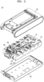
- FIG. 2 is a view of the battery pack shown in FIG. 1 in which a top case and a bottom case are separated from each other.
- FIG. 3 is a view of the battery pack shown in FIG. 1 in which a case holder and a plurality of battery cells are coupled to each other.
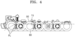
- FIG. 4 is a side view of FIG. 3 .
- FIG. 5 is a cross-sectional view of the battery pack taken along the line V - V in FIG. 3 .
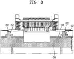
- FIG. 6 is a cross-sectional view of the battery pack taken along the line VI - VI in FIG. 3 .
- FIG. 7 is a perspective view of a lower holder shown in FIG. 3 .
- FIG. 8 is a perspective view of an upper holder shown in FIG. 3 .
- a battery pack 10 may include a plurality of battery cells 15, each having a cylindrical shape.
- the plurality of battery cells 15 may be fixed, e.g., fixed in position, by a case holder 40.
- the plurality of battery cells 15 may be arranged adjacent to one another in a first direction (e.g., an X direction).
- the case holder 40 may include an upper holder 50 and a lower holder 60.
- the case holder 40 may be a structure accommodating the plurality of battery cells and arranged inside the case 20.
- the upper holder 50 may fix the plurality of battery cells 15 in a form accommodating upper portions of the plurality of battery cells 15 in a radial direction (or radial shape) of the plurality of battery cells 15.
- the shape of an inner surface of the upper holder 50 may be adapted to the shapes of upper parts of battery cells 15.
- a profile of the upper holder 50 may include multiple partial circles.
- the lower holder 60 may be arranged to face the upper holder 50 with the plurality of battery cells 15 therebetween.
- the upper holder 50 and the lower holder 60 may support the plurality of battery cells 15 in a radial direction (e.g., may support a radial surface) of the plurality of battery cells 15 in the form of a sandwich.
- the shape of an inner surface of the lower holder 60 may be adapted to the shapes of lower parts of battery cells 15.
- a profile of the lower holder 60 may include multiple partial circles.
- a parting line PL that separates the upper holder 50 and the lower holder 60 from each other may include a plurality of lines.
- the plurality of lines may intersect with each other. For example, in areas of corners of the case holder 40, two of the plurality of lines forming the parting line PL may intersect.
- the upper holder 50 and the lower holder 60 may be respectively manufactured by injection molding of a synthetic resin.
- the parting line PL may be a dividing line separating the upper holder 50 and the lower holder 60 from each other.
- the plurality of lines of (or forming) the parting line PL may include a combination of straight lines parallel to a radial direction of the plurality of battery cells 15.
- the parting line PL includes a combination of a plurality of straight lines rather than one straight line, the upper holder 50 and the lower holder 60 may be effectively manufactured to be separated from each other.
- a complex structure may be intensively formed such that main components of the battery pack 10 may be installed on the upper holder 50.
- a structure for seating a battery management system (BMS) 70 on the upper holder 50 may be formed.
- BMS battery management system
- a locking device 80 for fixing or separating the battery pack 10 on or from an electronic device may be installed on the upper holder 50 or on the lower holder 60.
- a connection terminal 90 for electrically connecting the battery pack 10 to the electronic device may be installed on the upper holder 50 or on the lower holder 60.
- a structure of the lower holder 60 may be simplified (e.g., may be simplified as much as possible) to reduce a manufacturing cost of the battery pack 10. As such, when the parting line PL between the upper holder 50 and the lower holder 60 includes a plurality of straight lines, productivity may be improved.
- the lower holder 60 may include a fixing hook 62.
- the fixing hook 62 may be provided in plural. For example, 2n fixing hooks or 2n-2 fixing hooks may be provided, where n is the number of battery cells.
- the fixing hook 62 may protrude toward the upper holder 50.
- the fixing hook 62 may protrude perpendicularly to a straight line from among the plurality of straight lines of the parting line PL.
- the straight line is a horizontal line
- the fixing hook 62 may protrude in a vertical direction.
- the fixing hook 62 may protrude upwardly from a top surface of the lower holder 60.
- a hook shape to be caught in a hook coupling hole 52 described below, may be provided at an upper end of the fixing hook 62.
- the upper holder 50 may include the hook coupling hole 52.
- the hook coupling hole 52 may be provided in plural to correspond to the fixing hook 62.
- the upper holder may include one hook coupling hole 52 for each of the fixing hooks 62 of the lower holder 60.
- the hook coupling hole 52 may be formed to penetrate (or extend through) a top surface and a bottom surface of the upper holder 50.
- the hook coupling hole 52 may be formed, for example, as a rectangular hole (or opening).
- the fixing hook 62 may penetrate (or may extend through) the hook coupling hole 52.
- the upper end of the fixing hook 62 may be caught and fixed on the top surface of the hook coupling hole 52.
- the central line of the fixing hook 62 may be formed at a bisection point of a line segment connecting centers of adjacent battery cells 15. In other words, the hook may be located exactly in the center between two battery cells along the first direction.
- the central line of the fixing hook 62 is formed at the bisection point of the line segment connecting the centers of the adjacent battery cells 15, interference between the fixing hook 62 and the battery cell 15 may be effectively avoided.
- the fixing hook 62 may be formed about 3 mm to about 10 mm inside from the end of the battery cell 15 in the second direction. In other words, a distance between the fixing hook and one end of the battery cell along the second direction may be between 3 mm and 10 mm.
- the second direction may be the longitudinal direction of the battery cell 15. If the fixing hook 62 is formed less than about 3 mm inside from the end of the battery cell 15, a central portion of the battery cell 15 may not be effectively fixed. If the fixing hook 62 is formed greater than about 10 mm inside from the end of the battery cell 15, the end of the battery cell 15 may not be effectively fixed.
- the lower holder 60 may include a separation preventing projection 64.
- the separation preventing projection 64 may prevent the battery cells 15 from flowing in (e.g., moving in or shifting in) the longitudinal direction of the battery cell 15.
- the separation preventing projection 64 may prevent the plurality of battery cells 15 from being separated from the case holder 40.
- the separation preventing projection 64 may protrude in a radial direction of the plurality of battery cells 15.
- the separation preventing projection 64 may form a partial side wall of the lower holder 60.
- the separation preventing projection 64 may be arranged to be in contact with end surfaces of the plurality of battery cells 15.
- the BMS 70 is electrically connected to the plurality of battery cells 15 and a bus bar 72 and may be installed in the upper holder 50.
- the locking device 80 which connects the battery pack 10 to an electronic device, for example, a vacuum cleaner, and the connection terminal 90, etc., may be installed in the upper holder 50.
- the case holder 40 may be accommodated in a space formed by the top case 20 and the bottom case 30, thereby being further protected from an external shock.
- the battery pack 10 including the components as described above will be described, in detail, by describing an example of a process of assembling the battery pack 10.
- the plurality of battery cells 15 may be assembled to (or in) the lower holder 60.
- the BMS 70, the connection terminal 90, the locking device 80, etc. may be installed in advance on the upper holder 50.
- the hook coupling hole 52 of the upper holder 50 may be arranged to correspond to the fixing hook 62 provided in the lower holder 60. Pressure may be then applied in a direction causing the upper holder 50 and the lower holder 60 to be close to each other.
- the fixing hook 62 may be coupled through the hook coupling hole 52.
- the fixing hook 62 may be snap-fastend in the hook coupling hole 52.
- the hook shape provided at the upper end of the fixing hook 62 may be caught and fixed by an edge of the hook coupling hole 52.
- the plurality of battery cells 15 may be fixed by the case holder 40.
- An assembly of the plurality of battery cells 15 and the case holder 40 may be assembled while being accommodated in the top case 20 and the bottom case 30.
- the assembling of the battery pack 10 may be completed.
- it is not necessary to apply a urethane foam tape conventionally added to an inner surface of the bottom case 30 to prevent damage to the battery cells 15 in case of an external shock because, according to embodiments of the present disclosure, the upper holder 50 and the lower holder 60 may firmly protect the plurality of battery cells 15. Accordingly, shock resistance of the battery pack 10 may be improved.
- a cushioning member, like a conventionally applied urethane foam tape is omitted, the manufacturing cost of the battery pack 10 may be reduced.
- the radial direction of the plurality of battery cells 15 may be a third direction which may be orthogonal to the first direction and to the second direction.
- a conventional rib structure in the bottom case 30 may be omitted, thereby simplifying the structure of the bottom case 30 and, thus, reducing the manufacturing cost of the battery pack 10.
- a space between the battery cell 15 and the case may be secured, thereby reducing damage to the plurality of battery cells 15 in case of an external shock.
- the case holder for fixing the position of the battery cell includes the upper holder and the lower holder separated in the radial direction of the battery cells to protect the battery cells from an external shock applied to the battery pack, thereby improving shock resistance of the battery pack.
- the parting line for the upper holder and the lower holder includes a combination of the plurality of lines, a complex structure may be formed in the upper holder while the lower holder may be simplified, thereby improving productivity of the battery pack.
- the battery cells may be firmly fixed by the upper holder and the lower holder such that a conventional urethane foam tape applied to the inner surface of the battery case for preventing a shock may be omitted, thereby reducing the manufacturing cost of the battery pack.
Landscapes
- Chemical & Material Sciences (AREA)
- Chemical Kinetics & Catalysis (AREA)
- Electrochemistry (AREA)
- General Chemical & Material Sciences (AREA)
- Battery Mounting, Suspending (AREA)
Abstract
A battery pack includes: a plurality of battery cells (15) arranged adjacent to one another in a first direction; and a case holder (40) fixing the plurality of battery cells at a specific position. The case holder includes: an upper holder (50) accommodating a portion of the plurality of battery cells in a radial direction of the plurality of battery cells; and a lower holder (60) facing the upper holder with the plurality of battery cells therebetween and supporting the plurality of battery cells in the radial direction of the plurality of battery cells in a sandwich form.
Description
- Aspects of embodiments of the present disclosure relate to a battery pack.
- A secondary battery is a chargeable and dischargeable battery, different from a primary battery, which is not designed to be chargeable. Low-capacity secondary batteries are used in small portable electronic devices, such as smartphones, feature phones, laptop computers, digital cameras, and camcorders, and high-capacity secondary batteries are used as motor-driving power sources, power-storing batteries, etc., for hybrid vehicles, electric vehicles, etc. A secondary battery may generally include an electrode assembly including a cathode and an anode, a case accommodating the electrode assembly, an electrode terminal connected to the electrode assembly, etc.
- A battery pack includes a case holder for fixing a plurality of battery cells in a specific position. The case holder fixes the plurality of battery cells at the specific position while accommodating at least some of the plurality of battery cells. The case holder not only determines the position of the plurality of battery cells but also protects the plurality of battery cells if an external shock is applied thereto. If a shock is applied to the battery pack, the battery case cushions (or protects) the plurality of battery cells from a shock transfer. The case holder that fixes the plurality of battery cells inside the battery case also absorbs the shock.
- For example, in a battery pack including a conventional cylindrical battery cell, a case holder (e.g., a cell holder) that fixes the battery cell inside a battery case is configured to cover a radial upper portion of the battery cell. A radial lower portion of the battery cell is configured to be supported by the battery case. A rib structure extending from the battery case restrains the case holder. If the battery pack having this structure receives a shock, such as by being dropped, the rib structure of the battery case may damage the battery cell.
- The above-described information disclosed in this Background section provides the background of the present disclosure and is for improving understanding of the background of the present disclosure, and thus, it may include information that does not constitute related (or prior) art.
- Embodiments of the present disclosure include a battery pack having an improved case holder structure for fixing a battery cell from among components of the battery pack at a specific position to improve shock resistance and productivity of the battery pack while reducing a manufacturing cost of the battery pack.
- However, aspects and features of the present disclosure are not limited to the above-mentioned aspects and features, and other aspects and features not mentioned may be clearly understood by those of ordinary skill in the art from the description of embodiments of the present disclosure described below.
- Additional aspects and features will be set forth, in part, in the description which follows and, in part, will be apparent from the description or may be learned by practice of the presented embodiments of the present disclosure.
- According to an embodiment of the present disclosure, a battery pack includes: a plurality of battery cells arranged adjacent to one another in a first direction; and a case holder fixing the plurality of battery cells at a specific position. The case holder includes: an upper holder accommodating a portion of the plurality of battery cells in a radial direction of the plurality of battery cells; and a lower holder facing the upper holder with the plurality of battery cells therebetween and supporting the plurality of battery cells in the radial direction of the plurality of battery cells in a sandwich form. The radial direction may be orthogonal to the first direction. The lower holder and/or the upper holder may comprise wall portions that are adapted to the curvature of the outer surface of the battery cells.
- A parting line separating the upper holder and the lower holder from each other may include a plurality of lines. In other words, a boundary region between the upper holder and the lower holder can be described by more than one, e.g. two or three, straight lines. Thus, a first line, e.g., a first line describing a first contact area, between the lower holder and the upper holder in a first region may include an angle with a second line, e.g., a second line describing a second contact area, between the lower holder and the upper holder.
- The plurality of lines of the parting line may include a combination of straight lines parallel to the radial direction of the plurality of battery cells. For example, a first line among the plurality of lines may be parallel to the first direction, and a second line among the plurality of lines may be a radial direction of the plurality of battery cells, but may form an angle with the first direction. The second line forming an angle with the first direction may describe a contact area in an edge region of the upper holder and the lower holder.
- The lower holder may include a fixing hook, or a plurality of fixing hooks (for example, 2n fixing hooks or 2n-2 fixing hooks, where n is the number of battery cells), protruding (for example, from a dividing wall separating two battery cells from each other) toward the upper holder, and the upper holder may include a hook coupling hole, or a number of hook coupling holes corresponding to the number of fixing hooks of the lower holder, through which the fixing hook is fixed (or the fixing hooks are fixed).
- A central line of the fixing hook may be formed eccentrically from a center of the hook coupling hole.
- The central line of the fixing hook may be formed at a bisection point of a line segment connecting centers of adjacent ones of the battery cells.
- The fixing hook (e.g., a base of the fixing hook) may be formed at opposite ends in a longitudinal direction of the plurality of battery cells.
- The fixing hook may be (or be arranged) in a range of 3 mm to 10 mm inside, from an end of the plurality of battery cells, in a second direction. The second direction may be perpendicular to the first direction. The second direction may be a longitudinal direction of the plurality of battery cells.
- The lower holder may include a separation preventing projection configured to prevent separation of the plurality of battery cells in a longitudinal direction of the plurality of battery cells. The separation prevention projection may cover part of the end walls of the battery cells. The separation prevention projection may ensure that a battery cell does not detach from the composite along the second direction, for example along the longitudinal direction of the battery cell.
- The following drawings attached to this specification illustrate embodiments of the present disclosure and describe aspects and features of the present disclosure together with the detailed description of the present disclosure described later. The present disclosure should not be construed as being limited to the embodiments shown in the appended drawings.
- The above and other aspects and features of embodiments of the present disclosure will be more apparent from the following description taken in conjunction with the accompanying drawings.
-
FIG. 1 is a perspective view of a battery pack according to embodiments of the present disclosure; -
FIG. 2 is an exploded perspective view of the battery pack shown inFIG. 1 ; -
FIG. 3 is a perspective view of the battery pack shown inFIG. 1 ; -
FIG. 4 is a side view of the battery pack ofFIG. 3 ; -
FIG. 5 is a cross-sectional view of the battery pack taken along the line V - V inFIG. 3 ; -
FIG. 6 is a cross-sectional view of the battery pack taken along the line VI - VI inFIG. 3 ; -
FIG. 7 is a perspective view of a lower holder of the battery pack shown inFIG. 3 ; and -
FIG. 8 is a perspective view of an upper holder of the battery pack shown inFIG. 3 . - Reference will now be made, in detail, to embodiments, examples of which are illustrated in the accompanying drawings. In this regard, the described embodiments may have different forms and should not be construed as being limited to the descriptions set forth herein. Accordingly, embodiments are merely described below, by referring to the figures, to explain aspects and features of the present description.
- The terms and words used in the present specification and claims should not be construed as being limited to ordinary or dictionary meanings and should be interpreted as having meanings and concepts consistent with the technical idea of the present disclosure based on the principle that the inventors may appropriately define the concept of the terms to describe their invention in the best way. Therefore, it should be understood that the configurations shown in the drawings and embodiments described herein are example embodiments of the present disclosure, and do not represent all of the aspects and features of the present disclosure, such that there may be various equivalents and variations that replace them at the time of filing the present application.
- The statement that two elements are "the same" as each other may mean that they are "substantially the same" as each other. Thus, a case where two elements are "substantially the same" as each other may include a case where the two elements have a low-level deviation or a deviation a skilled person recognizes as low-level, for example, a deviation of 5% or less. If a uniform parameter is uniform in an area, it may mean that it is uniform from an average point of view (e.g., is uniformly average).
- It will be understood that when an element or layer is referred to as being "on," "connected to," or "coupled to" another element or layer, it may be directly on, connected, or coupled to the other element or layer or one or more intervening elements or layers may also be present. When an element or layer is referred to as being "directly on," "directly connected to," or "directly coupled to" another element or layer, there are no intervening elements or layers present. For example, when a first element is described as being "coupled" or "connected" to a second element, the first element may be directly coupled or connected to the second element or the first element may be indirectly coupled or connected to the second element via one or more intervening elements.
- In the figures, dimensions of the various elements, layers, etc. may be exaggerated for clarity of illustration. The same reference numerals designate the same elements. As used herein, the term "and/or" includes any and all combinations of one or more of the associated listed items. Further, the use of "may" when describing embodiments of the present disclosure relates to "one or more embodiments of the present disclosure." Expressions, such as "at least one of" and "any one of," when preceding a list of elements, modify the entire list of elements and do not modify the individual elements of the list. For example, the expression "at least one of a, b, or c" indicates only a, only b, only c, both a and b, both a and c, both b and c, all of a, b, and c, or variations thereof. As used herein, the terms "use," "using," and "used" may be considered synonymous with the terms "utilize," "utilizing," and "utilized," respectively. As used herein, the terms "substantially," "about," and similar terms are used as terms of approximation and not as terms of degree, and are intended to account for the inherent variations in measured or calculated values that would be recognized by those of ordinary skill in the art.
- It will be understood that, although the terms first, second, third, etc. may be used herein to describe various elements, components, regions, layers, and/or sections, these elements, components, regions, layers, and/or sections should not be limited by these terms. These terms are used to distinguish one element, component, region, layer, or section from another element, component, region, layer, or section. Thus, a first element, component, region, layer, or section discussed below could be termed a second element, component, region, layer, or section without departing from the teachings of example embodiments.
- Spatially relative terms, such as "beneath," "below," "lower," "above," "upper," and the like, may be used herein for ease of description to describe one element or feature's relationship to another element(s) or feature(s) as illustrated in the figures. It will be understood that the spatially relative terms are intended to encompass different orientations of the device in use or operation in addition to the orientation depicted in the figures. For example, if the device in the figures is turned over, elements described as "below" or "beneath" other elements or features would then be oriented "above" or "over" the other elements or features. Thus, the term "below" may encompass both an orientation of above and below. The device may be otherwise oriented (rotated 90 degrees or at other orientations), and the spatially relative descriptors used herein should be interpreted accordingly.
- The terminology used herein is for the purpose of describing embodiments of the present disclosure and is not intended to be limiting of the present disclosure. As used herein, the singular forms "a" and "an" are intended to include the plural forms as well, unless the context clearly indicates otherwise. It will be further understood that the terms "includes," "including," "comprises," and/or "comprising," when used in this specification, specify the presence of stated features, integers, steps, operations, elements, and/or components but do not preclude the presence or addition of one or more other features, integers, steps, operations, elements, components, and/or groups thereof.
-
FIG. 1 is a perspective view of a battery pack according to embodiments of the present disclosure.FIG. 2 is a view of the battery pack shown inFIG. 1 in which a top case and a bottom case are separated from each other.FIG. 3 is a view of the battery pack shown inFIG. 1 in which a case holder and a plurality of battery cells are coupled to each other.FIG. 4 is a side view ofFIG. 3 .FIG. 5 is a cross-sectional view of the battery pack taken along the line V - V inFIG. 3 .FIG. 6 is a cross-sectional view of the battery pack taken along the line VI - VI inFIG. 3 .FIG. 7 is a perspective view of a lower holder shown inFIG. 3 .FIG. 8 is a perspective view of an upper holder shown inFIG. 3 . - Referring to
FIGS. 1 to 8 , abattery pack 10, according to embodiments of the present disclosure, may include a plurality ofbattery cells 15, each having a cylindrical shape. The plurality ofbattery cells 15 may be fixed, e.g., fixed in position, by acase holder 40. The plurality ofbattery cells 15 may be arranged adjacent to one another in a first direction (e.g., an X direction). Thecase holder 40 may include anupper holder 50 and alower holder 60. Thecase holder 40 may be a structure accommodating the plurality of battery cells and arranged inside thecase 20. - The
upper holder 50 may fix the plurality ofbattery cells 15 in a form accommodating upper portions of the plurality ofbattery cells 15 in a radial direction (or radial shape) of the plurality ofbattery cells 15. For example, the shape of an inner surface of theupper holder 50 may be adapted to the shapes of upper parts ofbattery cells 15. A profile of theupper holder 50 may include multiple partial circles. - The
lower holder 60 may be arranged to face theupper holder 50 with the plurality ofbattery cells 15 therebetween. Theupper holder 50 and thelower holder 60 may support the plurality ofbattery cells 15 in a radial direction (e.g., may support a radial surface) of the plurality ofbattery cells 15 in the form of a sandwich. For example, the shape of an inner surface of thelower holder 60 may be adapted to the shapes of lower parts ofbattery cells 15. A profile of thelower holder 60 may include multiple partial circles. - A parting line PL that separates the
upper holder 50 and thelower holder 60 from each other may include a plurality of lines. The plurality of lines may intersect with each other. For example, in areas of corners of thecase holder 40, two of the plurality of lines forming the parting line PL may intersect. Theupper holder 50 and thelower holder 60 may be respectively manufactured by injection molding of a synthetic resin. - The parting line PL may be a dividing line separating the
upper holder 50 and thelower holder 60 from each other. The plurality of lines of (or forming) the parting line PL may include a combination of straight lines parallel to a radial direction of the plurality ofbattery cells 15. When the parting line PL includes a combination of a plurality of straight lines rather than one straight line, theupper holder 50 and thelower holder 60 may be effectively manufactured to be separated from each other. For example, a complex structure may be intensively formed such that main components of thebattery pack 10 may be installed on theupper holder 50. For example, a structure for seating a battery management system (BMS) 70 on theupper holder 50 may be formed. A lockingdevice 80 for fixing or separating thebattery pack 10 on or from an electronic device may be installed on theupper holder 50 or on thelower holder 60. Aconnection terminal 90 for electrically connecting thebattery pack 10 to the electronic device may be installed on theupper holder 50 or on thelower holder 60. A structure of thelower holder 60 may be simplified (e.g., may be simplified as much as possible) to reduce a manufacturing cost of thebattery pack 10. As such, when the parting line PL between theupper holder 50 and thelower holder 60 includes a plurality of straight lines, productivity may be improved. - A coupling structure of the
upper holder 50 and thelower holder 60 will now be described in detail. - The
lower holder 60 may include a fixinghook 62. The fixinghook 62 may be provided in plural. For example, 2n fixing hooks or 2n-2 fixing hooks may be provided, where n is the number of battery cells. The fixinghook 62 may protrude toward theupper holder 50. For example, the fixinghook 62 may protrude perpendicularly to a straight line from among the plurality of straight lines of the parting line PL. For example, when the straight line is a horizontal line, the fixinghook 62 may protrude in a vertical direction. The fixinghook 62 may protrude upwardly from a top surface of thelower holder 60. A hook shape to be caught in ahook coupling hole 52, described below, may be provided at an upper end of the fixinghook 62. - The
upper holder 50 may include thehook coupling hole 52. Thehook coupling hole 52 may be provided in plural to correspond to the fixinghook 62. For example, the upper holder may include onehook coupling hole 52 for each of the fixing hooks 62 of thelower holder 60. Thehook coupling hole 52 may be formed to penetrate (or extend through) a top surface and a bottom surface of theupper holder 50. Thehook coupling hole 52 may be formed, for example, as a rectangular hole (or opening). The fixinghook 62 may penetrate (or may extend through) thehook coupling hole 52. The upper end of the fixinghook 62 may be caught and fixed on the top surface of thehook coupling hole 52. When the fixinghook 62 and thehook coupling hole 52 are coupled to each other, a coupled state between theupper holder 50 and thelower holder 60 may be maintained. - A central line of the fixing
hook 62 may be formed (or extend) eccentrically from the center of thehook coupling hole 52. When the central line of the fixinghook 62 is formed eccentrically from the center of thehook coupling hole 52, the fixinghook 62 may not be easily separated from thehook coupling hole 52 after being coupled thereto. When the fixinghook 62 is coupled to thecoupling hole 52, an overlap between a portion of the fixinghook 62 and an upper surface of theupper holder 50 may be created. - The central line of the fixing
hook 62 may be formed at a bisection point of a line segment connecting centers ofadjacent battery cells 15. In other words, the hook may be located exactly in the center between two battery cells along the first direction. When the central line of the fixinghook 62 is formed at the bisection point of the line segment connecting the centers of theadjacent battery cells 15, interference between the fixinghook 62 and thebattery cell 15 may be effectively avoided. - The fixing hook 62 (or the fixing hooks 62) may be formed at (or may extend to) opposite ends of the
battery cell 15 in a longitudinal direction. The fixing hook 62 (or the fixing hooks 62) may be formed on the opposite ends of thebattery cell 15 in the longitudinal direction, that is, in a second direction (e.g., a Y direction), thereby firmly supporting an end and the other end of thebattery cells 15. Thus, thecase holder 40 may effectively protect thebattery cell 15 from an external shock. - The fixing
hook 62 may be formed about 3 mm to about 10 mm inside from the end of thebattery cell 15 in the second direction. In other words, a distance between the fixing hook and one end of the battery cell along the second direction may be between 3 mm and 10 mm. The second direction may be the longitudinal direction of thebattery cell 15. If the fixinghook 62 is formed less than about 3 mm inside from the end of thebattery cell 15, a central portion of thebattery cell 15 may not be effectively fixed. If the fixinghook 62 is formed greater than about 10 mm inside from the end of thebattery cell 15, the end of thebattery cell 15 may not be effectively fixed. - The
lower holder 60 may include aseparation preventing projection 64. Theseparation preventing projection 64 may prevent thebattery cells 15 from flowing in (e.g., moving in or shifting in) the longitudinal direction of thebattery cell 15. Theseparation preventing projection 64 may prevent the plurality ofbattery cells 15 from being separated from thecase holder 40. Theseparation preventing projection 64 may protrude in a radial direction of the plurality ofbattery cells 15. Theseparation preventing projection 64 may form a partial side wall of thelower holder 60. Theseparation preventing projection 64 may be arranged to be in contact with end surfaces of the plurality ofbattery cells 15. - The
BMS 70 is electrically connected to the plurality ofbattery cells 15 and abus bar 72 and may be installed in theupper holder 50. The lockingdevice 80, which connects thebattery pack 10 to an electronic device, for example, a vacuum cleaner, and theconnection terminal 90, etc., may be installed in theupper holder 50. - The
case holder 40 may be accommodated in a space formed by thetop case 20 and thebottom case 30, thereby being further protected from an external shock. - Hereinafter, the
battery pack 10 including the components as described above will be described, in detail, by describing an example of a process of assembling thebattery pack 10. - For example, the plurality of
battery cells 15 may be assembled to (or in) thelower holder 60. TheBMS 70, theconnection terminal 90, the lockingdevice 80, etc., may be installed in advance on theupper holder 50. Thehook coupling hole 52 of theupper holder 50 may be arranged to correspond to the fixinghook 62 provided in thelower holder 60. Pressure may be then applied in a direction causing theupper holder 50 and thelower holder 60 to be close to each other. Thus, the fixinghook 62 may be coupled through thehook coupling hole 52. The fixinghook 62 may be snap-fastend in thehook coupling hole 52. The hook shape provided at the upper end of the fixinghook 62 may be caught and fixed by an edge of thehook coupling hole 52. Thus, the plurality ofbattery cells 15 may be fixed by thecase holder 40. An assembly of the plurality ofbattery cells 15 and thecase holder 40 may be assembled while being accommodated in thetop case 20 and thebottom case 30. Thus, the assembling of thebattery pack 10 may be completed. As such, in the assembledbattery pack 10, it is not necessary to apply a urethane foam tape conventionally added to an inner surface of thebottom case 30 to prevent damage to thebattery cells 15 in case of an external shock because, according to embodiments of the present disclosure, theupper holder 50 and thelower holder 60 may firmly protect the plurality ofbattery cells 15. Accordingly, shock resistance of thebattery pack 10 may be improved. Moreover, because a cushioning member, like a conventionally applied urethane foam tape is omitted, the manufacturing cost of thebattery pack 10 may be reduced. - Because the
upper holder 50 and thelower holder 60 are assembled by using the fixinghook 62 and thehook coupling hole 52 in the radial direction of the plurality ofbattery cells 15, the ease of assembly may be improved. The radial direction of the plurality ofbattery cells 15 may be a third direction which may be orthogonal to the first direction and to the second direction. Moreover, a conventional rib structure in thebottom case 30 may be omitted, thereby simplifying the structure of thebottom case 30 and, thus, reducing the manufacturing cost of thebattery pack 10. In addition, when the rib structure of thebottom case 30 is removed or omitted, a space between thebattery cell 15 and the case may be secured, thereby reducing damage to the plurality ofbattery cells 15 in case of an external shock. - As described above, in the battery pack according to embodiments of the present disclosure, the case holder for fixing the position of the battery cell includes the upper holder and the lower holder separated in the radial direction of the battery cells to protect the battery cells from an external shock applied to the battery pack, thereby improving shock resistance of the battery pack. Moreover, according to embodiments of the present disclosure, when the parting line for the upper holder and the lower holder includes a combination of the plurality of lines, a complex structure may be formed in the upper holder while the lower holder may be simplified, thereby improving productivity of the battery pack. Furthermore, the battery cells may be firmly fixed by the upper holder and the lower holder such that a conventional urethane foam tape applied to the inner surface of the battery case for preventing a shock may be omitted, thereby reducing the manufacturing cost of the battery pack.
- While embodiments of the present disclosure are described herein, the present disclosure is not limited thereby and various modifications and changes may be made by those of ordinary skill in the art within the range of the claims set forth below.
- However, effects that may be obtained through the present disclosure are not limited to the above-described effects, and other technical effects not mentioned may be clearly understood by those of ordinary skill in the art from the description of the present disclosure described below.
- It should be understood that the embodiments described herein should be considered in a descriptive sense and not for purposes of limitation. Descriptions of features or aspects within each embodiment should typically be considered as available for other similar features or aspects in other embodiments. While one or more embodiments have been described with reference to the figures, it will be understood by those of ordinary skill in the art that various changes in form and details may be made therein without departing from the scope of the present disclosure as defined by the following claims.
Claims (9)
- A battery pack comprising:a plurality of battery cells (15) arranged adjacent to one another in a first direction; anda case holder (40) fixing the plurality of battery cells (15) at a specific position, the case holder (40) comprises:an upper holder (50) accommodating a portion of the plurality of battery cells (15) in a radial direction of the plurality of battery cells (15); anda lower holder (60) facing the upper holder (50) with the plurality of battery cells (15) therebetween and supporting the plurality of battery cells (15) in the radial direction of the plurality of battery cells (15) in a sandwich form.
- The battery pack as claimed in claim 1, wherein a parting line (PL) separating the upper holder (50) and the lower holder (60) from each other comprises a plurality of lines.
- The battery pack as claimed in claim 2, wherein the plurality of lines of the parting line (PL) comprises a combination of straight lines parallel to the radial direction of the plurality of battery cells (15).
- The battery pack as claimed in one of claims 1 to 3, wherein the lower holder (60) comprises a fixing hook (62) protruding toward the upper holder (50), and
wherein the upper holder (50) comprises a hook coupling hole (52) through which the fixing hook (62) is fixed. - The battery pack as claimed in claim 4, wherein a central line of the fixing hook (62) is formed eccentrically from a center of the hook coupling hole (52).
- The battery pack as claimed in claim 4 or claim 5, wherein the central line of the fixing hook (62) is formed at a bisection point of a line segment connecting centers of adjacent ones of the battery cells (15).
- The battery pack as claimed in one of claims 4 to 6, wherein the fixing hook (62) is formed at opposite ends in a longitudinal direction of the plurality of battery cells (15).
- The battery pack as claimed in claim 7, wherein the fixing hook (62) is in a range of 3 mm to 10 mm inside, from an end of the plurality of battery cells (15), in a second direction.
- The battery pack as claimed in claim 1, wherein the lower holder (60) comprises a separation preventing projection (64) configured to prevent separation of the plurality of battery cells (15) in a longitudinal direction of the plurality of battery cells (15).
Applications Claiming Priority (1)
| Application Number | Priority Date | Filing Date | Title |
|---|---|---|---|
| KR1020240002337A KR20250107585A (en) | 2024-01-05 | 2024-01-05 | Battery pack |
Publications (1)
| Publication Number | Publication Date |
|---|---|
| EP4583275A1 true EP4583275A1 (en) | 2025-07-09 |
Family
ID=91856085
Family Applications (1)
| Application Number | Title | Priority Date | Filing Date |
|---|---|---|---|
| EP24187078.1A Pending EP4583275A1 (en) | 2024-01-05 | 2024-07-08 | Battery pack |
Country Status (3)
| Country | Link |
|---|---|
| US (1) | US20250226500A1 (en) |
| EP (1) | EP4583275A1 (en) |
| KR (1) | KR20250107585A (en) |
Families Citing this family (6)
| Publication number | Priority date | Publication date | Assignee | Title |
|---|---|---|---|---|
| JP1755080S (en) * | 2021-12-15 | 2023-10-11 | battery pack | |
| JP1782584S (en) * | 2024-03-28 | 2024-10-21 | Storage battery | |
| USD1099014S1 (en) * | 2024-07-22 | 2025-10-21 | Jianwei Liu | Rechargeable battery |
| USD1103906S1 (en) * | 2024-07-24 | 2025-12-02 | Xiu Xia | Rechargeable battery |
| USD1104951S1 (en) * | 2024-07-24 | 2025-12-09 | Xiu Xia | Rechargeable battery |
| USD1099015S1 (en) * | 2024-07-25 | 2025-10-21 | Shenzhen Redsun Energy Technology Co., Ltd | Rechargeable battery |
Citations (2)
| Publication number | Priority date | Publication date | Assignee | Title |
|---|---|---|---|---|
| US7141330B2 (en) * | 2002-03-05 | 2006-11-28 | Sony Corporation | Secondary battery accomodation case |
| CN101777664A (en) * | 2009-01-13 | 2010-07-14 | 三星Sdi株式会社 | Battery pack |
Family Cites Families (1)
| Publication number | Priority date | Publication date | Assignee | Title |
|---|---|---|---|---|
| JP5496746B2 (en) | 2010-03-31 | 2014-05-21 | 三洋電機株式会社 | Battery pack |
-
2024
- 2024-01-05 KR KR1020240002337A patent/KR20250107585A/en active Pending
- 2024-04-23 US US18/643,485 patent/US20250226500A1/en active Pending
- 2024-07-08 EP EP24187078.1A patent/EP4583275A1/en active Pending
Patent Citations (2)
| Publication number | Priority date | Publication date | Assignee | Title |
|---|---|---|---|---|
| US7141330B2 (en) * | 2002-03-05 | 2006-11-28 | Sony Corporation | Secondary battery accomodation case |
| CN101777664A (en) * | 2009-01-13 | 2010-07-14 | 三星Sdi株式会社 | Battery pack |
Also Published As
| Publication number | Publication date |
|---|---|
| KR20250107585A (en) | 2025-07-14 |
| US20250226500A1 (en) | 2025-07-10 |
Similar Documents
| Publication | Publication Date | Title |
|---|---|---|
| US20250226500A1 (en) | Battery pack | |
| US8852789B2 (en) | Battery module having battery cell holder | |
| EP2408042B1 (en) | Battery pack | |
| EP2450990B1 (en) | Battery module having battery cell holder | |
| EP3151306B1 (en) | Rechargeable battery | |
| US9991483B2 (en) | Battery pack | |
| JP6305732B2 (en) | battery pack | |
| EP2763208B1 (en) | Battery pack | |
| US20230060014A1 (en) | Battery carrying tray provided with protecting structure | |
| EP4586379A1 (en) | Battery module | |
| US11552360B2 (en) | Cartridge and battery module comprising same | |
| KR102082868B1 (en) | Battery Pack | |
| US20230059084A1 (en) | Battery carrying tray provided with protecting structure | |
| CN103887457B (en) | Battery | |
| EP4439828A1 (en) | Cell holder for a battery pack and battery pack including the same | |
| EP3531466B1 (en) | Battery pack | |
| EP4614666A2 (en) | Secondary battery | |
| US12009537B2 (en) | Battery pack | |
| US20250079619A1 (en) | Battery cell holder and battery module including the same | |
| EP4723356A1 (en) | Busbar holder and battery module including same | |
| US20240347870A1 (en) | Rechargeable battery module | |
| US20250158213A1 (en) | Battery cell, and battery pack and vehicle including same |
Legal Events
| Date | Code | Title | Description |
|---|---|---|---|
| PUAI | Public reference made under article 153(3) epc to a published international application that has entered the european phase |
Free format text: ORIGINAL CODE: 0009012 |
|
| STAA | Information on the status of an ep patent application or granted ep patent |
Free format text: STATUS: REQUEST FOR EXAMINATION WAS MADE |
|
| 17P | Request for examination filed |
Effective date: 20240708 |
|
| AK | Designated contracting states |
Kind code of ref document: A1 Designated state(s): AL AT BE BG CH CY CZ DE DK EE ES FI FR GB GR HR HU IE IS IT LI LT LU LV MC ME MK MT NL NO PL PT RO RS SE SI SK SM TR |