EP4583272A1 - Battery assembly - Google Patents
Battery assembly Download PDFInfo
- Publication number
- EP4583272A1 EP4583272A1 EP25150197.9A EP25150197A EP4583272A1 EP 4583272 A1 EP4583272 A1 EP 4583272A1 EP 25150197 A EP25150197 A EP 25150197A EP 4583272 A1 EP4583272 A1 EP 4583272A1
- Authority
- EP
- European Patent Office
- Prior art keywords
- flame retardant
- battery cells
- battery
- battery assembly
- body portion
- Prior art date
- Legal status (The legal status is an assumption and is not a legal conclusion. Google has not performed a legal analysis and makes no representation as to the accuracy of the status listed.)
- Granted
Links
Images




Classifications
-
- H—ELECTRICITY
- H01—ELECTRIC ELEMENTS
- H01M—PROCESSES OR MEANS, e.g. BATTERIES, FOR THE DIRECT CONVERSION OF CHEMICAL ENERGY INTO ELECTRICAL ENERGY
- H01M50/00—Constructional details or processes of manufacture of the non-active parts of electrochemical cells other than fuel cells, e.g. hybrid cells
- H01M50/30—Arrangements for facilitating escape of gases
- H01M50/383—Flame arresting or ignition-preventing means
-
- H—ELECTRICITY
- H01—ELECTRIC ELEMENTS
- H01M—PROCESSES OR MEANS, e.g. BATTERIES, FOR THE DIRECT CONVERSION OF CHEMICAL ENERGY INTO ELECTRICAL ENERGY
- H01M50/00—Constructional details or processes of manufacture of the non-active parts of electrochemical cells other than fuel cells, e.g. hybrid cells
- H01M50/20—Mountings; Secondary casings or frames; Racks, modules or packs; Suspension devices; Shock absorbers; Transport or carrying devices; Holders
- H01M50/233—Mountings; Secondary casings or frames; Racks, modules or packs; Suspension devices; Shock absorbers; Transport or carrying devices; Holders characterised by physical properties of casings or racks, e.g. dimensions
- H01M50/24—Mountings; Secondary casings or frames; Racks, modules or packs; Suspension devices; Shock absorbers; Transport or carrying devices; Holders characterised by physical properties of casings or racks, e.g. dimensions adapted for protecting batteries from their environment, e.g. from corrosion
-
- H—ELECTRICITY
- H01—ELECTRIC ELEMENTS
- H01M—PROCESSES OR MEANS, e.g. BATTERIES, FOR THE DIRECT CONVERSION OF CHEMICAL ENERGY INTO ELECTRICAL ENERGY
- H01M50/00—Constructional details or processes of manufacture of the non-active parts of electrochemical cells other than fuel cells, e.g. hybrid cells
- H01M50/20—Mountings; Secondary casings or frames; Racks, modules or packs; Suspension devices; Shock absorbers; Transport or carrying devices; Holders
- H01M50/244—Secondary casings; Racks; Suspension devices; Carrying devices; Holders characterised by their mounting method
-
- H—ELECTRICITY
- H01—ELECTRIC ELEMENTS
- H01M—PROCESSES OR MEANS, e.g. BATTERIES, FOR THE DIRECT CONVERSION OF CHEMICAL ENERGY INTO ELECTRICAL ENERGY
- H01M50/00—Constructional details or processes of manufacture of the non-active parts of electrochemical cells other than fuel cells, e.g. hybrid cells
- H01M50/20—Mountings; Secondary casings or frames; Racks, modules or packs; Suspension devices; Shock absorbers; Transport or carrying devices; Holders
- H01M50/289—Mountings; Secondary casings or frames; Racks, modules or packs; Suspension devices; Shock absorbers; Transport or carrying devices; Holders characterised by spacing elements or positioning means within frames, racks or packs
- H01M50/291—Mountings; Secondary casings or frames; Racks, modules or packs; Suspension devices; Shock absorbers; Transport or carrying devices; Holders characterised by spacing elements or positioning means within frames, racks or packs characterised by their shape
-
- A—HUMAN NECESSITIES
- A62—LIFE-SAVING; FIRE-FIGHTING
- A62C—FIRE-FIGHTING
- A62C3/00—Fire prevention, containment or extinguishing specially adapted for particular objects or places
- A62C3/06—Fire prevention, containment or extinguishing specially adapted for particular objects or places of highly inflammable material, e.g. light metals, petroleum products
-
- A—HUMAN NECESSITIES
- A62—LIFE-SAVING; FIRE-FIGHTING
- A62C—FIRE-FIGHTING
- A62C3/00—Fire prevention, containment or extinguishing specially adapted for particular objects or places
- A62C3/16—Fire prevention, containment or extinguishing specially adapted for particular objects or places in electrical installations, e.g. cableways
-
- H—ELECTRICITY
- H01—ELECTRIC ELEMENTS
- H01M—PROCESSES OR MEANS, e.g. BATTERIES, FOR THE DIRECT CONVERSION OF CHEMICAL ENERGY INTO ELECTRICAL ENERGY
- H01M10/00—Secondary cells; Manufacture thereof
- H01M10/60—Heating or cooling; Temperature control
- H01M10/64—Heating or cooling; Temperature control characterised by the shape of the cells
- H01M10/647—Prismatic or flat cells, e.g. pouch cells
-
- H—ELECTRICITY
- H01—ELECTRIC ELEMENTS
- H01M—PROCESSES OR MEANS, e.g. BATTERIES, FOR THE DIRECT CONVERSION OF CHEMICAL ENERGY INTO ELECTRICAL ENERGY
- H01M10/00—Secondary cells; Manufacture thereof
- H01M10/60—Heating or cooling; Temperature control
- H01M10/65—Means for temperature control structurally associated with the cells
- H01M10/658—Means for temperature control structurally associated with the cells by thermal insulation or shielding
-
- H—ELECTRICITY
- H01—ELECTRIC ELEMENTS
- H01M—PROCESSES OR MEANS, e.g. BATTERIES, FOR THE DIRECT CONVERSION OF CHEMICAL ENERGY INTO ELECTRICAL ENERGY
- H01M50/00—Constructional details or processes of manufacture of the non-active parts of electrochemical cells other than fuel cells, e.g. hybrid cells
- H01M50/20—Mountings; Secondary casings or frames; Racks, modules or packs; Suspension devices; Shock absorbers; Transport or carrying devices; Holders
- H01M50/289—Mountings; Secondary casings or frames; Racks, modules or packs; Suspension devices; Shock absorbers; Transport or carrying devices; Holders characterised by spacing elements or positioning means within frames, racks or packs
- H01M50/293—Mountings; Secondary casings or frames; Racks, modules or packs; Suspension devices; Shock absorbers; Transport or carrying devices; Holders characterised by spacing elements or positioning means within frames, racks or packs characterised by the material
-
- H—ELECTRICITY
- H01—ELECTRIC ELEMENTS
- H01M—PROCESSES OR MEANS, e.g. BATTERIES, FOR THE DIRECT CONVERSION OF CHEMICAL ENERGY INTO ELECTRICAL ENERGY
- H01M50/00—Constructional details or processes of manufacture of the non-active parts of electrochemical cells other than fuel cells, e.g. hybrid cells
- H01M50/50—Current conducting connections for cells or batteries
- H01M50/502—Interconnectors for connecting terminals of adjacent batteries; Interconnectors for connecting cells outside a battery casing
-
- H—ELECTRICITY
- H01—ELECTRIC ELEMENTS
- H01M—PROCESSES OR MEANS, e.g. BATTERIES, FOR THE DIRECT CONVERSION OF CHEMICAL ENERGY INTO ELECTRICAL ENERGY
- H01M50/00—Constructional details or processes of manufacture of the non-active parts of electrochemical cells other than fuel cells, e.g. hybrid cells
- H01M50/50—Current conducting connections for cells or batteries
- H01M50/502—Interconnectors for connecting terminals of adjacent batteries; Interconnectors for connecting cells outside a battery casing
- H01M50/503—Interconnectors for connecting terminals of adjacent batteries; Interconnectors for connecting cells outside a battery casing characterised by the shape of the interconnectors
-
- H—ELECTRICITY
- H01—ELECTRIC ELEMENTS
- H01M—PROCESSES OR MEANS, e.g. BATTERIES, FOR THE DIRECT CONVERSION OF CHEMICAL ENERGY INTO ELECTRICAL ENERGY
- H01M50/00—Constructional details or processes of manufacture of the non-active parts of electrochemical cells other than fuel cells, e.g. hybrid cells
- H01M50/50—Current conducting connections for cells or batteries
- H01M50/502—Interconnectors for connecting terminals of adjacent batteries; Interconnectors for connecting cells outside a battery casing
- H01M50/505—Interconnectors for connecting terminals of adjacent batteries; Interconnectors for connecting cells outside a battery casing comprising a single busbar
-
- H—ELECTRICITY
- H01—ELECTRIC ELEMENTS
- H01M—PROCESSES OR MEANS, e.g. BATTERIES, FOR THE DIRECT CONVERSION OF CHEMICAL ENERGY INTO ELECTRICAL ENERGY
- H01M50/00—Constructional details or processes of manufacture of the non-active parts of electrochemical cells other than fuel cells, e.g. hybrid cells
- H01M50/20—Mountings; Secondary casings or frames; Racks, modules or packs; Suspension devices; Shock absorbers; Transport or carrying devices; Holders
- H01M50/204—Racks, modules or packs for multiple batteries or multiple cells
-
- H—ELECTRICITY
- H01—ELECTRIC ELEMENTS
- H01M—PROCESSES OR MEANS, e.g. BATTERIES, FOR THE DIRECT CONVERSION OF CHEMICAL ENERGY INTO ELECTRICAL ENERGY
- H01M50/00—Constructional details or processes of manufacture of the non-active parts of electrochemical cells other than fuel cells, e.g. hybrid cells
- H01M50/20—Mountings; Secondary casings or frames; Racks, modules or packs; Suspension devices; Shock absorbers; Transport or carrying devices; Holders
- H01M50/204—Racks, modules or packs for multiple batteries or multiple cells
- H01M50/207—Racks, modules or packs for multiple batteries or multiple cells characterised by their shape
- H01M50/209—Racks, modules or packs for multiple batteries or multiple cells characterised by their shape adapted for prismatic or rectangular cells
-
- H—ELECTRICITY
- H01—ELECTRIC ELEMENTS
- H01M—PROCESSES OR MEANS, e.g. BATTERIES, FOR THE DIRECT CONVERSION OF CHEMICAL ENERGY INTO ELECTRICAL ENERGY
- H01M50/00—Constructional details or processes of manufacture of the non-active parts of electrochemical cells other than fuel cells, e.g. hybrid cells
- H01M50/20—Mountings; Secondary casings or frames; Racks, modules or packs; Suspension devices; Shock absorbers; Transport or carrying devices; Holders
- H01M50/204—Racks, modules or packs for multiple batteries or multiple cells
- H01M50/207—Racks, modules or packs for multiple batteries or multiple cells characterised by their shape
- H01M50/211—Racks, modules or packs for multiple batteries or multiple cells characterised by their shape adapted for pouch cells
-
- Y—GENERAL TAGGING OF NEW TECHNOLOGICAL DEVELOPMENTS; GENERAL TAGGING OF CROSS-SECTIONAL TECHNOLOGIES SPANNING OVER SEVERAL SECTIONS OF THE IPC; TECHNICAL SUBJECTS COVERED BY FORMER USPC CROSS-REFERENCE ART COLLECTIONS [XRACs] AND DIGESTS
- Y02—TECHNOLOGIES OR APPLICATIONS FOR MITIGATION OR ADAPTATION AGAINST CLIMATE CHANGE
- Y02E—REDUCTION OF GREENHOUSE GAS [GHG] EMISSIONS, RELATED TO ENERGY GENERATION, TRANSMISSION OR DISTRIBUTION
- Y02E60/00—Enabling technologies; Technologies with a potential or indirect contribution to GHG emissions mitigation
- Y02E60/10—Energy storage using batteries
Definitions
- the present disclosure relates to a battery assembly.
- a secondary battery is a battery that is made to convert electrical energy into chemical energy and store it so that it may be reused multiple times through charging and discharging.
- Secondary batteries are widely used across industries due to their economical and eco-friendly characteristics.
- lithium secondary batteries are widely used throughout industries, including portable devices that require high-density energy.
- Secondary batteries may generate a large amount of heat when charged and discharged. When the heat generated inside is not quickly extinguished, the fire may propagated to adjacent battery cells, causing major damage. Therefore, one of the major tasks is to quickly extinguish the heat generated inside a secondary battery and prevent the propagation of fire.
- a plurality of secondary batteries may be grouped together to manufacture a battery module or battery pack. At this time, a fire that occurs in one of the plurality of secondary batteries may cause the battery module or battery pack to burn completely. Therefore, it is necessary to prevent this risk.
- a problem that the present disclosure aims to solve is to improve the stability of a battery assembly by delaying the propagation of fire to adjacent battery cells.
- the present disclosure can be widely applied in the field of green technology, such as electric vehicles, battery charging stations, solar power generation, and wind power generation using batteries.
- the present disclosure can be used in eco-friendly electric vehicles, hybrid vehicles, and the like to prevent climate change by suppressing air pollution and greenhouse gas emissions.
- a battery assembly of the present disclosure includes: a plurality of battery cells, which each include a main body portion storing and supplying electric energy and a tab portion protruding outwardly from the main body portion and electrically connecting the main body portion and the outside and are stacked along one direction; an accommodating housing accommodating the plurality of battery cells therein; a busbar assembly positioned inside the accommodating housing and including a through-hole formed on one surface thereof, wherein the tab portion is inserted into the through-hole to electrically connect at least a part of the plurality of battery cells to each other; and a pillar-shaped flame retardant portion positioned in an insertion space formed between the main body portion and the busbar assembly by tab portions of two adjacent battery cells among the plurality of battery cells.
- the accommodating housing may include: an accommodating body supporting the plurality of battery cells; and an accommodating cover coupled to the accommodating body and covering the plurality of battery cells, and the flame retardant portion may be positioned on the accommodating body.
- the flame retardant portion may be in contact with the accommodating body.
- the length of the flame retardant portion may be less than or equal to the length of the main body portion along the height direction formed perpendicular to the protruding direction of the tab portion and the stacking direction in which the plurality of battery cells are stacked.
- the length of the flame retardant portion may be 80% or more of the length of the main body portion along the height direction formed perpendicular to the protruding direction of the tab portion and the stacking direction in which the plurality of battery cells are stacked.
- the length of the flame retardant portion may be less than or equal to a gap between tab portions provided in each of two adjacent battery cells among the plurality of battery cells along the stacking direction in which the plurality of battery cells are stacked.
- the head portion and the floor portion may each include a cone shape having one truncated end including a vertex.
- the head portion may have the same shape as the floor portion.
- the body portion may have an outer surface formed into a curved surface.
- the body portion may be provided in the form of a cylinder.
- the flame retardant portion may include a material having a flame retardancy rating of V0 or higher according to UL94 standards.
- the flame retardant portion may include at least one material of flame retardant polyurethane, silicone, modified polyphenylene oxide (MPPO), polypropylene, polyoxymethylene, acetal, polyamide 6, polyamide 6-6, and polycarbonate .
- MPPO modified polyphenylene oxide
- the stability of a battery assembly can be improved by delaying the propagation of fire to adjacent battery cells.
- expressions such as “same” and “is the same” not only indicate a strictly identical state, but also indicate a state in which there is a difference in tolerance or the degree to which the same function is obtained.
- Each axis direction refers to both directions in which each axis extends.
- FIG. 1 shows a diagram illustrating a battery cell 110 according to one embodiment of the present disclosure
- FIG. 2 shows a diagram illustrating a battery assembly 100 according to one embodiment of the present disclosure.
- the battery cell 110 described herein refers to a secondary battery that may be repeatedly used by charging and discharging electric energy.
- a lithium secondary battery or a lithium ion battery but is not limited thereto.
- it may refer to an all-solid-state battery.
- Battery cells 110 may be classified into a pouch-type secondary battery, a prismatic secondary battery, or a cylindrical secondary battery depending on its shape.
- a pouch-type secondary battery is illustrated herein as an example for convenience of explanation, but is not limited thereto.
- a battery cell 110 may include a main body portion 111 and a tab portion 112.
- a main body portion 111 may store and supply electric energy.
- a main body portion 111 may include a cathode and an anode.
- a main body portion 111 may include an electrode assembly formed by stacking a cathode and an anode.
- a cathode may include a cathode active material, and an anode may include an anode active material.
- a cathode active material may be a material which lithium ions may be inserted into and extracted from, and an anode active material may be a material which lithium ions may be absorbed into and extracted from.
- a tab portion 112 may be formed to protrude outwardly of a main body portion 111.
- a tab portion 112 may be connected to each of a cathode and an anode and may protrude outwardly of a main body portion 111.
- a tab portion 112 may include a cathode tab 112a connected to a cathode and an anode tab 112b connected to an anode.
- a cathode tab 112a and an anode tab 112b may protrude in opposite directions.
- a cathode tab 112a may protrude along the +X direction
- an anode tab 112b may protrude along the -X direction.
- a tab portion 112 may electrically connect a main body portion 111 to the outside.
- a tab portion 112 may be connected to each of a cathode and an anode of a main body portion 111 to supply electric energy stored in the main body portion 111 to the outside.
- a battery assembly 100 described herein refers to battery cells 110 grouped into one or more groups and placed in a case to protect the battery cells from external impact, heat, vibration, and the like and to impart high-output and high-capacity properties.
- a battery assembly 100 may refer to a battery module or a battery pack.
- a battery module is described herein as an example of a battery assembly 100.
- a battery assembly 100 of the present disclosure may include a plurality of battery cells 110 and an accommodating housing 120 accommodating the same therein. This is to protect a plurality of battery cells 110 from external foreign substances or impacts and assemble them into a single unit.
- a accommodating housing 120 may include an accommodating body 121 accommodating a plurality of battery cells 110 and an accommodating cover 122 coupled to the accommodating body 121 to form a space in which the plurality of battery cells 110 are accommodated together with the accommodating body 121.
- a busbar 132 may be coupled to one surface of a busbar plate 131.
- a busbar plate 131 may include a first surface facing a tab portion 112 of a plurality of battery cells 110 and a second surface opposite to the first surface.
- a busbar 132 may be provided on a second surface of a busbar plate 131.
- the flame retardant portion 140 may have a smooth and rounded surface.
- a flame retardant portion 140 may not to include sharp corners, such as those of a rectangular cuboid.
- FIG. 6 shows a diagram illustrating a flame retardant portion 140 according to one embodiment of the present disclosure
- FIG. 7 shows a diagram illustrating a head portion according to one embodiment of the present disclosure.
- a flame retardant portion 140 may include a head portion 141, a body portion 142, and a floor portion 143.
- a head portion 141 may be formed at one end of a flame retardant portion 140, and a floor portion 143 may be formed at the other end of the flame retardant portion 140 opposite the one end.
- a body portion 142 may connect a head portion 141 and a floor portion 143.
- a floor portion 143 may be positioned toward an accommodating body 121, and a head portion 141 may be positioned toward an accommodating cover 122.
- a body portion 142 may extend in the Z-direction, which is the height direction, so that the shape of a flame retardant portion 140 may correspond to the shape of an insertion space 160.
- the cross-sectional area of a head portion 141 and a floor portion 143 may decrease along directions towards each outermost side from a body portion 142.
- the direction from a body portion 142 to the outermost side of a head portion 141 refers to the +Z-direction. In addition, this may refer to the direction from a body portion 142 to a head portion 141.
- a head portion 141 and a floor portion 143 may each include a flat surface formed perpendicular to the direction in which a body portion 142 extends. This is to minimize damage to a battery assembly 100 and to stably maintain a flame retardant portion 140 in the battery assembly 100.
- a body portion 142 may extend along the Z-direction, and an XY plane may be formed perpendicular to the Z-direction.
- a head portion 141 may include one surface parallel to the XY plane.
- a floor portion 143 may also include one surface parallel to the XY plane.
- a head portion 141 and a floor portion 143 may include a cone shape having one truncated end including a vertex.
- a head portion 141 and a floor portion 143 may each include a plurality of cone shapes having one truncated end including a vertex. The bottoms and edges of the plurality of cones may each have different angles.
- FIG. 7 illustrates a head portion and describes the head portion 141, but the description may also be applied to a floor portion 143.
- a head portion 141 and a floor portion 143 have shapes that are upside down along the Z-direction, when applying the description of the head portion to the floor portion, the description may be applied in the opposite direction to the description of the head portion in the Z-direction.
- the head portion 141 has an identical shape as the floor portion 143.
- a head portion 141 may include a first head portion 200 and a second head portion 210.
- a floor portion 143 may include a first floor portion (not shown) and a second floor portion (not shown).
- a first head portion 200 and a second head portion 210 may each have a truncated cone shape including a vertex.
- a first head portion 200 may include a first lower surface 201 and a first upper surface 211 positioned above the first lower surface 201 along the Z-direction.
- a first lower surface 201 and a first upper surface 211 may be positioned parallel.
- a first head portion 200 may include a first side surface 202 connecting a first lower surface 201 and a first upper surface 211.
- a second head portion 210 may include a second lower surface 211 and a second upper surface 221 positioned above the second lower surface 211 along the Z-direction.
- a second head portion may include a second side surface 212 connecting a second lower surface 211 and a second upper surface 221.
- a first head portion 200 and a second head portion 210 may be formed to be connected to each other. As a result, a first head portion and a second head portion may share a cross-section 211.
- a cross section 211 may form a first upper surface 211 of a first head portion 200 and a second lower surface 211 of the second head portion 210.
- a first upper surface 211 and a second lower surface 211 may refer to a same surface.
- the angle A1 formed by a first lower surface 201 and a first side surface 202 may be formed to be larger than the angle A2 formed by a second lower surface 211 and a second side surface 212.
- a first side surface may be formed to have a steeper slope than a second side surface with respect to the XY plane. As the slope becomes more gentle toward the outermost side along the Z-direction, a side surface of a head portion may be formed without being sharp, and damage caused by collision between a head portion and adjacent components can be minimized.
- a cross-section of a second surface 211 orthogonally projected toward the XY plane may be positioned within a first surface 201.
- the area of a second surface 211 may be formed to be smaller than the area of a first surface 201. Through this, a slope may be formed gently toward the outermost side along the Z-direction, and a stable structure may be formed.
- a head portion 141 and a floor portion 143 may have a side surface formed as a curved surface, and may each include one surface 1411 and 1431 provided flat.
- An outer surface of a body portion 142 may be formed as a curved surface. As described above, this is to minimize damage to a battery assembly 100 caused by a flame retardant portion 140. When a body portion 142 has an angled corner, damage may occur to an assembly due to the corner. When a body portion 142 is formed as a curved surface, the pressure applied to adjacent components may be distributed, and damage caused by collision with a flame retardant portion 140 may be minimized.
- a body portion 142 may be provided as a cylinder.
- a head portion 141 and a floor portion 143 of a flame retardant portion 140 may be provided as at each of both ends of a body portion 142 provided as a cylinder.
- a flame retardant portion 140 may include a fire-resistant and flame-retardant material to minimize the propagation of fire.
- a flame retardant portion 140 may include a material having a flame retardancy rating of V-0 or higher according to the UL94 standard.
- the UL94 standard classifies flame retardancy ratings according to a test that evaluates flame retardancy of plastics. The flame retardancy ratings may be classified into HB, V2, V1, V0, and 5V, with V2 rating materials having the lowest flame retardancy and thus being flammable, and 5V rating materials having the highest flame retardancy and thus being non-flammable.
Landscapes
- Chemical & Material Sciences (AREA)
- Chemical Kinetics & Catalysis (AREA)
- General Chemical & Material Sciences (AREA)
- Electrochemistry (AREA)
- Health & Medical Sciences (AREA)
- Public Health (AREA)
- Business, Economics & Management (AREA)
- Emergency Management (AREA)
- Engineering & Computer Science (AREA)
- Manufacturing & Machinery (AREA)
- Oil, Petroleum & Natural Gas (AREA)
- Battery Mounting, Suspending (AREA)
Abstract
Description
- The present disclosure relates to a battery assembly.
- A secondary battery is a battery that is made to convert electrical energy into chemical energy and store it so that it may be reused multiple times through charging and discharging. Secondary batteries are widely used across industries due to their economical and eco-friendly characteristics. In particular, among secondary batteries, lithium secondary batteries are widely used throughout industries, including portable devices that require high-density energy.
- The operating principle of lithium secondary batteries is an electrochemical oxidation-reduction reaction. In other words, the principle is that electricity is generated through the movement of lithium ions and charged in the reverse process. In the case of a lithium secondary battery, a phenomenon in which lithium ions in an anode escape therefrom and move to a cathode through an electrolyte and a separator is referred to as discharge. In addition, the opposite process of this phenomenon is referred to as charging.
- Secondary batteries may generate a large amount of heat when charged and discharged. When the heat generated inside is not quickly extinguished, the fire may propagated to adjacent battery cells, causing major damage. Therefore, one of the major tasks is to quickly extinguish the heat generated inside a secondary battery and prevent the propagation of fire.
- In order to achieve high-capacity and high-output properties, a plurality of secondary batteries may be grouped together to manufacture a battery module or battery pack. At this time, a fire that occurs in one of the plurality of secondary batteries may cause the battery module or battery pack to burn completely. Therefore, it is necessary to prevent this risk.
- A problem that the present disclosure aims to solve is to improve the stability of a battery assembly by delaying the propagation of fire to adjacent battery cells.
- In addition, the present disclosure can be widely applied in the field of green technology, such as electric vehicles, battery charging stations, solar power generation, and wind power generation using batteries.
- In addition, the present disclosure can be used in eco-friendly electric vehicles, hybrid vehicles, and the like to prevent climate change by suppressing air pollution and greenhouse gas emissions.
- A battery assembly of the present disclosure includes: a plurality of battery cells, which each include a main body portion storing and supplying electric energy and a tab portion protruding outwardly from the main body portion and electrically connecting the main body portion and the outside and are stacked along one direction; an accommodating housing accommodating the plurality of battery cells therein; a busbar assembly positioned inside the accommodating housing and including a through-hole formed on one surface thereof, wherein the tab portion is inserted into the through-hole to electrically connect at least a part of the plurality of battery cells to each other; and a pillar-shaped flame retardant portion positioned in an insertion space formed between the main body portion and the busbar assembly by tab portions of two adjacent battery cells among the plurality of battery cells.
- The accommodating housing may include: an accommodating body supporting the plurality of battery cells; and an accommodating cover coupled to the accommodating body and covering the plurality of battery cells, and the flame retardant portion may be positioned on the accommodating body.
- The flame retardant portion may be in contact with the accommodating body.
- The length of the flame retardant portion may be less than or equal to the length of the main body portion along the height direction formed perpendicular to the protruding direction of the tab portion and the stacking direction in which the plurality of battery cells are stacked.
- The length of the flame retardant portion may be 80% or more of the length of the main body portion along the height direction formed perpendicular to the protruding direction of the tab portion and the stacking direction in which the plurality of battery cells are stacked.
- The length of the flame retardant portion may be less than or equal to a gap between tab portions provided in each of two adjacent battery cells among the plurality of battery cells along the stacking direction in which the plurality of battery cells are stacked.
- The flame retardant portion may include: a head portion formed at one end; a floor portion formed at the other end opposite to the one end; and a body portion connecting the head portion and the floor portion, and the head portion and the floor portion may have a shape in which the cross-sectional area decreases along the direction toward each of the outermost sides of the body portion.
- The head portion and the floor portion may each include one flat surface formed perpendicular to the direction in which the body portion extends.
- The head portion and the floor portion may each include a cone shape having one truncated end including a vertex.
- The head portion may have the same shape as the floor portion.
- The body portion may have an outer surface formed into a curved surface.
- The body portion may be provided in the form of a cylinder.
- The flame retardant portion may include a material having a flame retardancy rating of V0 or higher according to UL94 standards.
- The flame retardant portion may include at least one material of flame retardant polyurethane, silicone, modified polyphenylene oxide (MPPO), polypropylene, polyoxymethylene, acetal, polyamide 6, polyamide 6-6, and polycarbonate .
- According to one embodiment of the present disclosure, the stability of a battery assembly can be improved by delaying the propagation of fire to adjacent battery cells.
-
-
FIG. 1 shows a diagram illustrating a battery cell according to one embodiment of the present disclosure. -
FIG. 2 shows a diagram illustrating a battery assembly according to one embodiment of the present disclosure. -
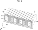
FIGS. 3 and4 show diagrams illustrating one cross-section of a battery assembly according to one embodiment of the present disclosure. -
FIG. 5 shows a diagram illustrating a battery cell and a flame retardant portion according to one embodiment of the present disclosure. -
FIG. 6 shows a diagram illustrating a flame retardant portion according to one embodiment of the present disclosure. -
FIG. 7 shows a diagram illustrating a head portion according to one embodiment of the present disclosure. - Hereinafter, the present disclosure will be described in detail with reference to the attached drawings. This is merely illustrative, and the present disclosure is not limited to the specific embodiments described in an illustrative manner.
- Specific terms used in the present specification are merely for convenience of explanation and are not used to limit the illustrated embodiments.
- For example, expressions such as "same" and "is the same" not only indicate a strictly identical state, but also indicate a state in which there is a difference in tolerance or the degree to which the same function is obtained.
- For example, expressions representing relative or absolute arrangement such as "in a certain direction," "along a certain direction," "side by side," "perpendicularly," "at the center," "concentric," or "coaxial," not only strictly represent the arrangement, but also represent the state of relative displacement with a tolerance, or an angle or distance at which the same function is obtained.
- To explain the present disclosure, it will be described below based on a spatial orthogonal coordinate system with X, Y, and Z axes orthogonal to each other. Each axis direction (X-axis direction, Y-axis direction, Z-axis direction) refers to both directions in which each axis extends.
- The X-direction, Y-direction, and Z-direction mentioned below are for explanation so that the present disclosure may be clearly understood, and of course, the directions may be defined differently depending on where the reference is placed.
- The use of terms such as 'first, second, and third' in front of the components mentioned below is only to avoid confusion about the components to which they are referred and is irrelevant to the order, importance, or master-slave relationship between the components, etc. For example, an invention that includes only a second component without a first component may also be implemented.
- As used in this specification, singular expressions include plural expressions unless the context clearly dictates otherwise.
-
FIG. 1 shows a diagram illustrating abattery cell 110 according to one embodiment of the present disclosure, andFIG. 2 shows a diagram illustrating abattery assembly 100 according to one embodiment of the present disclosure. - The
battery cell 110 described herein refers to a secondary battery that may be repeatedly used by charging and discharging electric energy. For example, it may refer to a lithium secondary battery or a lithium ion battery, but is not limited thereto. As another example, it may refer to an all-solid-state battery. -
Battery cells 110 may be classified into a pouch-type secondary battery, a prismatic secondary battery, or a cylindrical secondary battery depending on its shape. A pouch-type secondary battery is illustrated herein as an example for convenience of explanation, but is not limited thereto. - Referring to
FIG. 1 , abattery cell 110 may include amain body portion 111 and atab portion 112. Amain body portion 111 may store and supply electric energy. Amain body portion 111 may include a cathode and an anode. For example, amain body portion 111 may include an electrode assembly formed by stacking a cathode and an anode. - A cathode may include a cathode active material, and an anode may include an anode active material. A cathode active material may be a material which lithium ions may be inserted into and extracted from, and an anode active material may be a material which lithium ions may be absorbed into and extracted from.
- A
tab portion 112 may be formed to protrude outwardly of amain body portion 111. Atab portion 112 may be connected to each of a cathode and an anode and may protrude outwardly of amain body portion 111. Atab portion 112 may include acathode tab 112a connected to a cathode and ananode tab 112b connected to an anode. - In an embodiment, a
cathode tab 112a and ananode tab 112b may protrude in opposite directions. For example, referring toFIG. 1 , acathode tab 112a may protrude along the +X direction, and ananode tab 112b may protrude along the -X direction. - A
tab portion 112 may electrically connect amain body portion 111 to the outside. Atab portion 112 may be connected to each of a cathode and an anode of amain body portion 111 to supply electric energy stored in themain body portion 111 to the outside. - Meanwhile, a
battery assembly 100 described herein refers tobattery cells 110 grouped into one or more groups and placed in a case to protect the battery cells from external impact, heat, vibration, and the like and to impart high-output and high-capacity properties. For example, abattery assembly 100 may refer to a battery module or a battery pack. For convenience of explanation, a battery module is described herein as an example of abattery assembly 100. - Referring to
FIG. 2 , abattery assembly 100 of the present disclosure may include a plurality ofbattery cells 110 and anaccommodating housing 120 accommodating the same therein. This is to protect a plurality ofbattery cells 110 from external foreign substances or impacts and assemble them into a single unit. - A
accommodating housing 120 may include anaccommodating body 121 accommodating a plurality ofbattery cells 110 and anaccommodating cover 122 coupled to theaccommodating body 121 to form a space in which the plurality ofbattery cells 110 are accommodated together with theaccommodating body 121. - An
accommodating body 121 may include anopening 1211 that is open upward and may accommodate a plurality ofbattery cells 110 through theopening 1211. Anaccommodating cover 122 may be coupled to anaccommodating body 121 to close anopening 1211. - A
battery assembly 100 may further include anend cover 150. Anend cover 150 may be coupled to both sides of anaccommodating body 121 to form one side surface of an accommodation space. For example, anend cover 150 may be coupled to anaccommodating body 121 along the X-direction. - As a result, a
battery assembly 100 may form a hexahedron by anaccommodating housing 120 and anend cover 150. Through this structure, abattery cell 110 positioned in the inside may be efficiently protected from external impact. - A
battery assembly 100 of the present disclosure may further include a busbar assembly 130. A busbar assembly 130 may be positioned inside anaccommodating housing 120 and include a through-hole 1311 (FIG. 3 ) formed on one surface thereof, and atab portion 112 may be inserted into the through-hole 1311. A busbar assembly 130 may electrically connect at least a part of a plurality ofbattery cells 110 to each other. - A busbar assembly 130 may include a
busbar plate 131 and abusbar 132. Abusbar plate 131 may extend along a direction in which a plurality ofbattery cells 110 are stacked. A plurality ofbattery cells 110 may be positioned so that their wide surfaces face each other to improve stacking efficiency. For example, referring toFIG. 2 , a plurality ofbattery cells 110 may be stacked along the Y-direction. - A
busbar plate 131 may be positioned to face atab portion 112 provided on each of a plurality ofbattery cells 110. As a result, abusbar plate 131 may be positioned to face atab portion 112 and have a rectangular shape extending along the stacking direction ofbattery cells 110. A plurality ofbusbar plates 131 may be provided. - A
busbar plate 131 may include a through-hole 1311 for atab portion 112 to be inserted therethrough. A through-hole 1311 may be provided in a slit shape with one side open, but is not limited thereto. Atab portion 112 may be inserted through the through-hole 1311, thereby connecting a plurality ofbattery cells 110 and abusbar plate 131. - A
busbar 132 may be coupled to one surface of abusbar plate 131. In an embodiment, abusbar plate 131 may include a first surface facing atab portion 112 of a plurality ofbattery cells 110 and a second surface opposite to the first surface. Abusbar 132 may be provided on a second surface of abusbar plate 131. - A
busbar 132 may include an insertion hole 1321 (FIG. 3 ). Atab portion 112 may be inserted into aninsertion hole 1321. Through this, atab portion 112 and abusbar 132 may be electrically connected. Aninsertion hole 1321 may be provided at a position corresponding to a through-hole 1311 along the insertion direction of atab portion 112. This is to insert atab portion 112 also into abusbar 132 after the tab portion is inserted into a thebusbar plate 131. As a result, atab portion 112 may be inserted into each of abusbar plate 131 and abusbar 132. - A busbar assembly 130 may include at least one
busbar 132. Through this, a plurality ofbattery cells 110 may be electrically connected in series or in parallel. - A
battery assembly 100 of the present disclosure may include aflame retardant portion 140. Aflame retardant portion 140 may be positioned in aninsertion space 160 formed between amain body portion 111 and a busbar assembly 130 bytab portions 112 of twoadjacent battery cells 110 among a plurality ofbattery cells 110. Aflame retardant portion 140 may be provided in a pillar shape and occupy most of the area of aninsertion space 160. - Referring to
FIG. 2 , aflame retardant portion 140 may be positioned between abusbar plate 131 and amain body portion 111. In addition, aflame retardant portion 140 may be positioned betweentap portions 112 of any onebattery cell 110 among a plurality ofbattery cells 110 and of anotheradjacent battery cell 110. In other words, aflame retardant portion 140 may occupy aninsertion space 160 formed betweentab portions 112 of twoadjacent battery cells 110. - When a fire occurs in one
battery cell 110, the fire may be rapidly propagated toadjacent battery cells 110. In particular, a fire may be propagated through empty spaces within abattery assembly 100. To prevent this, it is necessary to fill the empty spaces within abattery assembly 100 with a flame retardant material. The present disclosure can prevent fire propagation by filling aninsertion space 160, which is an empty space within abattery assembly 100, with aflame retardant portion 140. -
FIGS. 3 and4 show diagrams illustrating one cross-section of abattery assembly 100 according to one embodiment of the present disclosure. - Specifically,
FIGS. 3 and4 illustratetab portions 112 of a plurality ofbattery cells 110 inserted into a busbar assembly 130. Atab portion 112 may be inserted into a through-hole 1311 and aninsertion hole 1321 to be connected to a busbar assembly 130. At this time, aninsertion space 160 may be formed by atab portion 112 of twoadjacent battery cells 110, amain body portion 111, and a busbar assembly 130. Referring toFIG. 3 , a plurality ofinsertion spaces 160 may be formed. - A
flame retardant portion 140 may be positioned in aninsertion space 160. Aflame retardant portion 140 may occupy an area of aninsertion space 160 to prevent a fire from being propagated. Aflame retardant portion 140 may block a path through which a fire is propagated. Aflame retardant portion 140 may be formed in a pillar shape. - A
flame retardant portion 140 may be provided in a shape corresponding to aninsertion space 160 of anaccommodating body 121. In an embodiment, aflame retardant portion 140 may be in contact with at least one of atab portion 112, amain body portion 111, and a busbar assembly 130. - Referring to
FIG. 4 , aflame retardant portion 140 may be positioned on aaccommodating body 121. Aflame retardant portion 140 may be fixed to anaccommodating body 121, but is not limited thereto. Aflame retardant portion 140 may be in contact with anaccommodating body 121. - Meanwhile, a
battery assembly 100 of the present disclosure may further include a blockingportion 170. A blockingportion 170 may be positioned between a plurality ofbattery cells 110. A blockingportion 170 may be stacked together with a plurality ofbattery cells 110 along a direction in which the plurality ofbattery cells 110 are stacked. Referring toFIG. 3 , a blockingportion 170 may be positioned between twoadjacent battery cells 110. A blockingportion 170 may be formed of a flame retardant material to prevent fire propagation. -
FIG. 5 shows a diagram illustrating abattery cell 110 and aflame retardant portion 140 according to one embodiment of the present disclosure. - A
flame retardant portion 140 may be provided in a pillar shape. Aflame retardant portion 140 may extend along the height direction formed perpendicular to a protruding direction of atab portion 112 and a stacking direction in which a plurality ofbattery cells 110 are stacked. Referring toFIG. 5 , the height direction refers to the Z-direction. In other words, aflame retardant portion 140 may extend along the Z-direction to occupy aninsertion space 160 inside abattery assembly 100. - The length L1 of a
flame retardant portion 140 along the height direction may be less than or equal to the length L3 of amain body portion 111. When the length L1 of aflame retardant portion 140 along the height direction is provided to be longer than the length L3 of amain body portion 111, aflame retardant portion 140 may protrude outwardly from themain body portion 111. This may reduce the ease of assembly and make it difficult to efficiently use the space. Therefore, aflame retardant portion 140 may be provided preferably with a length less than or equal to the length of amain body portion 111. - The length of a
flame retardant portion 140 along the height direction may be 80% or more of the length of amain body portion 111. When the length of aflame retardant portion 140 is less than 80% of the length of amain body portion 111, a fire may still be propagated to a remaining space of aninsertion space 160, and the fire may not be prevented from being propagated. - The length L2 of a flame retardant portion along the stacking direction in which a plurality of battery cells are stacked may be less than or equal to the ha L4 between tab portions provided in each of two adjacent battery cells among the plurality of battery cells.
- Referring to
FIG. 5 , sincebattery cells 110 are stacked along the Y-direction, the stacking direction refers to the Y-direction. As described above, the length of aflame retardant portion 140 along the Y-direction should be less than or equal to the gap between tab portions so that theflame retardant portion 140 may be stably positioned in aninsertion space 160. - Meanwhile, the length of a
flame retardant portion 140 along the Y-direction may preferably be more than half the gap between tab portions. Through this shape, aflame retardant portion 140 may occupy most of the space of aninsertion space 160 and delay the propagation of a fire. - Ultimately, it is preferable that a
flame retardant portion 140 is provided in a shape to occupy most of the area of aninsertion space 160, thereby physically blocking the path through which a fire is propagated. - To minimize damage caused by a
flame retardant portion 140, it may be preferable for theflame retardant portion 140 to have a smooth and rounded surface. For example, it may be preferable for aflame retardant portion 140 not to include sharp corners, such as those of a rectangular cuboid. -
FIG. 6 shows a diagram illustrating aflame retardant portion 140 according to one embodiment of the present disclosure, andFIG. 7 shows a diagram illustrating a head portion according to one embodiment of the present disclosure. - Referring to
FIG. 6 , aflame retardant portion 140 may include ahead portion 141, abody portion 142, and afloor portion 143. Ahead portion 141 may be formed at one end of aflame retardant portion 140, and afloor portion 143 may be formed at the other end of theflame retardant portion 140 opposite the one end. Abody portion 142 may connect ahead portion 141 and afloor portion 143. - Referring to
FIGS. 3 to 5 again, afloor portion 143 may be positioned toward anaccommodating body 121, and ahead portion 141 may be positioned toward anaccommodating cover 122. In addition, abody portion 142 may extend in the Z-direction, which is the height direction, so that the shape of aflame retardant portion 140 may correspond to the shape of aninsertion space 160. - Meanwhile, the cross-sectional area of a
head portion 141 and afloor portion 143 may decrease along directions towards each outermost side from abody portion 142. For example, referring toFIG. 6 , the direction from abody portion 142 to the outermost side of ahead portion 141 refers to the +Z-direction. In addition, this may refer to the direction from abody portion 142 to ahead portion 141. - The cross-sectional area of a
head portion 141 may decrease along the +Z-direction. The cross-sectional area of ahead portion 141 refers to the area of a virtual cross-section cut through thehead portion 141 along a direction perpendicular to the direction from abody portion 142 to the outermost side of thehead portion 141. In other words, the cross-sectional area of ahead portion 141 refers to the area of a virtual cross-section cut through thehead portion 141 along the XY plane. - A
head portion 141 may include afirst cross-section 145 positioned relatively close to abody portion 142 and asecond cross-section 146 positioned close to the outermost side. At this time, the cross-sectional area of thefirst cross-section 145 may be larger than the cross-sectional area of thesecond cross-section 146. Through this structure, the side surface of thehead portion 141 may be formed smoothly, and damage to abattery assembly 100 caused by aflame retardant portion 140 may be minimized. - Referring to the above description, the cross-sectional area of a
floor portion 143 may decrease along the -Z-direction. The cross-sectional area of afloor portion 143 refers to the area of a virtual cross-section that cuts through thefloor portion 143 along a direction perpendicular to the direction toward the outermost side of thefloor portion 143 from abody portion 142. - A
head portion 141 and afloor portion 143 may each include a flat surface formed perpendicular to the direction in which abody portion 142 extends. This is to minimize damage to abattery assembly 100 and to stably maintain aflame retardant portion 140 in thebattery assembly 100. - Referring to
FIG. 6 , abody portion 142 may extend along the Z-direction, and an XY plane may be formed perpendicular to the Z-direction. Ahead portion 141 may include one surface parallel to the XY plane. In addition, afloor portion 143 may also include one surface parallel to the XY plane. - In an embodiment, a
head portion 141 and afloor portion 143 may include a cone shape having one truncated end including a vertex. Ahead portion 141 and afloor portion 143 may each include a plurality of cone shapes having one truncated end including a vertex. The bottoms and edges of the plurality of cones may each have different angles. -
FIG. 7 illustrates a head portion and describes thehead portion 141, but the description may also be applied to afloor portion 143. Specifically, since ahead portion 141 and afloor portion 143 have shapes that are upside down along the Z-direction, when applying the description of the head portion to the floor portion, the description may be applied in the opposite direction to the description of the head portion in the Z-direction. In other words, Thehead portion 141 has an identical shape as thefloor portion 143. - Referring to
FIG. 7 , ahead portion 141 may include afirst head portion 200 and asecond head portion 210. Similarly, afloor portion 143 may include a first floor portion (not shown) and a second floor portion (not shown). - A
first head portion 200 and asecond head portion 210 may each have a truncated cone shape including a vertex. Afirst head portion 200 may include a firstlower surface 201 and a firstupper surface 211 positioned above the firstlower surface 201 along the Z-direction. A firstlower surface 201 and a firstupper surface 211 may be positioned parallel. - A
first head portion 200 may include afirst side surface 202 connecting a firstlower surface 201 and a firstupper surface 211. Asecond head portion 210 may include a secondlower surface 211 and a secondupper surface 221 positioned above the secondlower surface 211 along the Z-direction. A second head portion may include asecond side surface 212 connecting a secondlower surface 211 and a secondupper surface 221. - A
first head portion 200 and asecond head portion 210 may be formed to be connected to each other. As a result, a first head portion and a second head portion may share across-section 211. Across section 211 may form a firstupper surface 211 of afirst head portion 200 and a secondlower surface 211 of thesecond head portion 210. In other words, a firstupper surface 211 and a secondlower surface 211 may refer to a same surface. - The angle A1 formed by a first
lower surface 201 and afirst side surface 202 may be formed to be larger than the angle A2 formed by a secondlower surface 211 and asecond side surface 212. In other words, a first side surface may be formed to have a steeper slope than a second side surface with respect to the XY plane. As the slope becomes more gentle toward the outermost side along the Z-direction, a side surface of a head portion may be formed without being sharp, and damage caused by collision between a head portion and adjacent components can be minimized. - In an embodiment, a cross-section of a
second surface 211 orthogonally projected toward the XY plane may be positioned within afirst surface 201. In addition, the area of asecond surface 211 may be formed to be smaller than the area of afirst surface 201. Through this, a slope may be formed gently toward the outermost side along the Z-direction, and a stable structure may be formed. - In an embodiment, a
head portion 141 and afloor portion 143 may have a side surface formed as a curved surface, and may each include onesurface - A
flame retardant portion 140 may be symmetrical with respect to an imaginary plane parallel to the XY plane. In other words, afloor portion 143 and ahead portion 141 may be formed symmetrically. Through this, afloor portion 143 may be positioned so that it faces anaccommodating cover 122 and ahead portion 141 faces anaccommodating body 121. Afloor portion 143 and ahead portion 141 may be provided symmetrically, so that the assembly efficiency of abattery assembly 100 can be improved. When afloor portion 143 and ahead portion 141 are distinguished, thefloor portion 143 should be inserted so that it faces anaccommodating body 121. - In contrast, when a
floor portion 143 and ahead portion 141 are provided symmetrically, aflame retardant portion 140 may be inserted simply into aninsertion space 160 without having to distinguish between thefloor portion 143 and thehead portion 141. - In addition, it may be preferable for a
flame retardant portion 140 to have a shape symmetrical with respect to an imaginary plane parallel to the XZ plane, and it may be preferable for aflame retardant portion 140 to have a shape symmetrical with respect to an imaginary plane parallel to the YZ plane. - An outer surface of a
body portion 142 may be formed as a curved surface. As described above, this is to minimize damage to abattery assembly 100 caused by aflame retardant portion 140. When abody portion 142 has an angled corner, damage may occur to an assembly due to the corner. When abody portion 142 is formed as a curved surface, the pressure applied to adjacent components may be distributed, and damage caused by collision with aflame retardant portion 140 may be minimized. - For example, a
body portion 142 may be provided as a cylinder. As a result, ahead portion 141 and afloor portion 143 of aflame retardant portion 140 may be provided as at each of both ends of abody portion 142 provided as a cylinder. - A
flame retardant portion 140 may include a fire-resistant and flame-retardant material to minimize the propagation of fire. Aflame retardant portion 140 may include a material having a flame retardancy rating of V-0 or higher according to the UL94 standard. The UL94 standard classifies flame retardancy ratings according to a test that evaluates flame retardancy of plastics. The flame retardancy ratings may be classified into HB, V2, V1, V0, and 5V, with V2 rating materials having the lowest flame retardancy and thus being flammable, and 5V rating materials having the highest flame retardancy and thus being non-flammable. - The
flame retardant portion 140 of the present disclosure may include a material having a V0 rating or higher. Aflame retardant portion 140 may include a flame retardant material classified as a V0 rating or a 5V rating. For example, aflame retardant portion 140 may include at least one material of flame retardant polyurethane, silicone, modified polyphenylene oxide (MPPO), polypropylene, polyoxymethylene, acetal, polyamide 6, polyamide 6-6, and polycarbonate. - Some of the aspects of the present disclosure are as follows:
- Aspect 1: A battery assembly (100) comprising:
- a plurality of battery cells (110), which each include a main body portion (111) storing and supplying electric energy and a tab portion (112) protruding outwardly from the main body portion (111) and electrically connecting the main body portion (111) and the outside and are stacked along one direction;
- an accommodating housing (120) accommodating the plurality of battery cells (110) therein;
- a busbar assembly (130) positioned inside the accommodating housing (120) and including a through-hole (1311) formed on one surface thereof, wherein the tab portion (112) is inserted into the through-hole (1311) to electrically connect at least a part of the plurality of battery cells (110) to each other; and
- a pillar-shaped flame retardant portion (140) positioned in an insertion space (160) formed between the main body portion (111) and the busbar assembly (130) by tab portions (112) of two adjacent battery cells (110) among the plurality of battery cells (110).
- Aspect 2: The battery assembly (100) according to aspect 1, wherein the accommodating housing (120) includes an accommodating body (121) supporting the plurality of battery cells (110); and
- an accommodating cover (122) coupled to the accommodating body (121) and covering the plurality of battery cells (110),
- wherein the flame retardant portion (140) is positioned on the accommodating body (121).
- Aspect 3: The battery assembly (100) according to aspect 2, wherein the flame retardant portion (140) is in contact with the accommodating body (121).
- Aspect 4: The battery assembly (100) according to according to any one of aspects 1 to 3, wherein the length (L1) of the flame retardant portion (140) is less than or equal to the length (L3) of the main body portion (111) along the height direction formed perpendicular to the protruding direction of the tab portion (112) and the stacking direction in which the plurality of battery cells (110) are stacked.
- Aspect 5: The battery assembly (100) according to aspect 4, wherein the length (L1) of the flame retardant portion (140) is 80% or more of the length (L3) of the main body portion (111) along the height direction formed perpendicular to the protruding direction of the tab portion (112) and the stacking direction in which the plurality of battery cells (110) are stacked.
- Aspect 6: The battery assembly (100) according to any one of aspects 1 to 5, wherein the length (L2) of the flame retardant portion (140) is less than or equal to a gap (L4) between tab portions (112) provided in each of two adjacent battery cells (110) among the plurality of battery cells (110) along the stacking direction in which the plurality of battery cells (110) are stacked.
- Aspect 7: The battery assembly (100) according to any one of aspects 1 to 6, wherein the flame retardant portion (140) includes: a head portion (141) formed at one end; a floor portion (143) formed at the other end opposite to the one end; and a body portion (142) connecting the head portion (141) and the floor portion (143), wherein the head portion (141) and the floor portion (143) have a shape in which the cross-sectional area decreases along the direction toward each of the outermost sides of the body portion (142).
- Aspect 8: The battery assembly (100) according to aspect 7, wherein the head portion (141) and the floor portion (143) each include one flat surface formed perpendicular to the direction in which the body portion (142) extends.
- Aspect 9: The battery assembly (100) according to aspect 8, wherein the head portion (141) and the floor portion (143) each include a cone shape having one truncated end including a vertex.
- Aspect 10: The battery assembly (100) according to aspect 8 or 9, the head portion (141) has the same shape as the floor portion (143).
- Aspect 11: The battery assembly (100) according to any one of aspects 7 to 10, wherein the body portion (142) has an outer surface formed into a curved surface.
- Aspect 12: The battery assembly (100) according to aspect 11, wherein the body portion (142) is provided in the form of a cylinder.
- Aspect 13: The battery assembly (100) according to any one of the preceding aspects, wherein the flame retardant portion (140) includes a material having a flame retardancy rating of V0 or higher according to UL94 standards.
- Aspect 14: The battery assembly (100) according to aspect 13, wherein the flame retardant portion (140) includes at least one material of flame retardant polyurethane, silicone, modified polyphenylene oxide (MPPO), polypropylene, polyoxymethylene, acetal, polyamide 6, polyamide 6-6, and polycarbonate.
- The above description is merely examples of applying the principles of the present disclosure, and other components may be further included without departing from the scope of the present invention.
Claims (14)
- A battery assembly (100) comprising:a plurality of battery cells (110), which each include a main body portion (111) storing and supplying electric energy and a tab portion (112) protruding outwardly from the main body portion (111) and electrically connecting the main body portion (111) and the outside and are stacked along one direction;an accommodating housing (120) accommodating the plurality of battery cells (110) therein;a busbar assembly (130) positioned inside the accommodating housing (120) and including a through-hole (1311) formed on one surface thereof, wherein the tab portion (112) is inserted into the through-hole (1311) to electrically connect at least a part of the plurality of battery cells (110) to each other; anda pillar-shaped flame retardant portion (140) positioned in an insertion space (160) formed between the main body portion (111) and the busbar assembly (130) by tab portions (112) of two adjacent battery cells (110) among the plurality of battery cells (110).
- The battery assembly (100) according to claim 1, wherein the accommodating housing (120) includes an accommodating body (121) supporting the plurality of battery cells (110); andan accommodating cover (122) coupled to the accommodating body (121) and covering the plurality of battery cells (110),wherein the flame retardant portion (140) is positioned on the accommodating body (121).
- The battery assembly (100) according to claim 2, wherein the flame retardant portion (140) is in contact with the accommodating body (121).
- The battery assembly (100) according to according to any one of claims 1 to 3, wherein the length of the flame retardant portion (140) is less than or equal to the length of the main body portion (111) along the height direction formed perpendicular to the protruding direction of the tab portion (112) and the stacking direction in which the plurality of battery cells (110) are stacked.
- The battery assembly (100) according to claim 4, wherein the length of the flame retardant portion (140) is 80% or more of the length of the main body portion (111) along the height direction formed perpendicular to the protruding direction of the tab portion (112) and the stacking direction in which the plurality of battery cells (110) are stacked.
- The battery assembly (100) according to any one of claims 1 to 5, wherein the length of the flame retardant portion (140) is less than or equal to a gap between tab portions (112) provided in each of two adjacent battery cells (110) among the plurality of battery cells (110) along the stacking direction in which the plurality of battery cells (110) are stacked.
- The battery assembly (100) according to any one of claims 1 to 6, wherein the flame retardant portion (140) includes: a head portion (141) formed at one end; a floor portion (143) formed at the other end opposite to the one end; and a body portion (142) connecting the head portion (141) and the floor portion (143), wherein the head portion (141) and the floor portion (143) have a shape in which the cross-sectional area decreases along the direction toward each of the outermost sides of the body portion (142).
- The battery assembly (100) according to claim 7, wherein the head portion (141) and the floor portion (143) each include one flat surface formed perpendicular to the direction in which the body portion (142) extends.
- The battery assembly (100) according to claim 8, wherein the head portion (141) and the floor portion (143) each include a cone shape having one truncated end including a vertex.
- The battery assembly (100) according to claim 8 or 9, the head portion (141) has the same shape as the floor portion (143).
- The battery assembly (100) according to any one of claims 7 to 10, wherein the body portion (142) has an outer surface formed into a curved surface.
- The battery assembly (100) according to claim 11, wherein the body portion (142) is provided in the form of a cylinder.
- The battery assembly (100) according to any one of the preceding claims, wherein the flame retardant portion (140) includes a material having a flame retardancy rating of V0 or higher according to UL94 standards.
- The battery assembly according to claim 13, wherein the flame retardant portion includes at least one material of flame retardant polyurethane, silicone, modified polyphenylene oxide (MPPO), polypropylene, polyoxymethylene, acetal, polyamide 6, polyamide 6-6, or polycarbonate.
Applications Claiming Priority (1)
| Application Number | Priority Date | Filing Date | Title |
|---|---|---|---|
| KR1020240001573A KR20250106945A (en) | 2024-01-04 | 2024-01-04 | Battery Assembly |
Publications (2)
| Publication Number | Publication Date |
|---|---|
| EP4583272A1 true EP4583272A1 (en) | 2025-07-09 |
| EP4583272B1 EP4583272B1 (en) | 2026-04-15 |
Family
ID=94173022
Family Applications (1)
| Application Number | Title | Priority Date | Filing Date |
|---|---|---|---|
| EP25150197.9A Active EP4583272B1 (en) | 2024-01-04 | 2025-01-03 | Battery assembly |
Country Status (4)
| Country | Link |
|---|---|
| US (1) | US20250226526A1 (en) |
| EP (1) | EP4583272B1 (en) |
| KR (1) | KR20250106945A (en) |
| CN (1) | CN120261876A (en) |
Families Citing this family (1)
| Publication number | Priority date | Publication date | Assignee | Title |
|---|---|---|---|---|
| EP4478514A1 (en) | 2023-06-02 | 2024-12-18 | SK On Co., Ltd. | Battery assembly and method of assembling the same |
Citations (3)
| Publication number | Priority date | Publication date | Assignee | Title |
|---|---|---|---|---|
| WO2021002626A1 (en) * | 2019-07-03 | 2021-01-07 | 주식회사 엘지화학 | Battery module, battery rack comprising same, and power storage device |
| JP2023534415A (en) * | 2021-02-24 | 2023-08-09 | エルジー エナジー ソリューション リミテッド | Battery modules and battery packs containing the same |
| WO2023239216A1 (en) * | 2022-06-10 | 2023-12-14 | 주식회사 엘지에너지솔루션 | Battery pack and vehicle comprising same |
-
2024
- 2024-01-04 KR KR1020240001573A patent/KR20250106945A/en active Pending
-
2025
- 2025-01-03 EP EP25150197.9A patent/EP4583272B1/en active Active
- 2025-01-06 CN CN202510016699.9A patent/CN120261876A/en active Pending
- 2025-01-06 US US19/010,173 patent/US20250226526A1/en active Pending
Patent Citations (3)
| Publication number | Priority date | Publication date | Assignee | Title |
|---|---|---|---|---|
| WO2021002626A1 (en) * | 2019-07-03 | 2021-01-07 | 주식회사 엘지화학 | Battery module, battery rack comprising same, and power storage device |
| JP2023534415A (en) * | 2021-02-24 | 2023-08-09 | エルジー エナジー ソリューション リミテッド | Battery modules and battery packs containing the same |
| WO2023239216A1 (en) * | 2022-06-10 | 2023-12-14 | 주식회사 엘지에너지솔루션 | Battery pack and vehicle comprising same |
Also Published As
| Publication number | Publication date |
|---|---|
| US20250226526A1 (en) | 2025-07-10 |
| KR20250106945A (en) | 2025-07-11 |
| EP4583272B1 (en) | 2026-04-15 |
| CN120261876A (en) | 2025-07-04 |
Similar Documents
| Publication | Publication Date | Title |
|---|---|---|
| JP7580837B2 (en) | Battery module and battery pack including same | |
| US20240194977A1 (en) | Battery module, and battery rack and energy storage system including the same | |
| WO2022134055A1 (en) | Battery box body, battery, electric device, and method and device for manufacturing box body | |
| CN111937180B (en) | Battery modules including internal panels, battery packs including the battery modules and vehicles | |
| US20230361405A1 (en) | Battery module with improved fire protection performance | |
| EP4583272B1 (en) | Battery assembly | |
| EP4376176A1 (en) | Battery module | |
| KR20250145661A (en) | Batteries, electrical appliances and energy storage devices | |
| KR20230152577A (en) | Battery module, battery pack and vehicle including same | |
| CN117859237A (en) | Battery module, battery pack including the battery module, and vehicle | |
| JP2023114147A (en) | battery pack | |
| KR20230121108A (en) | Batteries, electrical devices, methods and equipment for manufacturing batteries | |
| US20240204341A1 (en) | Battery cell, battery cell manufacturing method and equipment, battery, and electrical device | |
| US20240222751A1 (en) | Battery module, battery pack including the battery module, and energy storage system and vehicle including the battery pack | |
| JP2024527875A (en) | Battery module, battery pack, and automobile including same | |
| CN117999696A (en) | Battery pack with improved safety | |
| US20240266655A1 (en) | Battery cell and battery pack including the same | |
| US20260058245A1 (en) | Battery assembly | |
| US20250099792A1 (en) | Battery module | |
| US20250391981A1 (en) | Battery assembly | |
| CN114696022A (en) | Battery case, battery, electrical equipment, method and device for preparing case | |
| EP4421949A1 (en) | Battery case and battery pack including the same | |
| EP4704231A1 (en) | Battery assembly and battery pack | |
| US20260018733A1 (en) | Battery module and battery pack | |
| US20250253478A1 (en) | Battery assembly |
Legal Events
| Date | Code | Title | Description |
|---|---|---|---|
| PUAI | Public reference made under article 153(3) epc to a published international application that has entered the european phase |
Free format text: ORIGINAL CODE: 0009012 |
|
| STAA | Information on the status of an ep patent application or granted ep patent |
Free format text: STATUS: REQUEST FOR EXAMINATION WAS MADE |
|
| 17P | Request for examination filed |
Effective date: 20250103 |
|
| AK | Designated contracting states |
Kind code of ref document: A1 Designated state(s): AL AT BE BG CH CY CZ DE DK EE ES FI FR GB GR HR HU IE IS IT LI LT LU LV MC ME MK MT NL NO PL PT RO RS SE SI SK SM TR |
|
| GRAP | Despatch of communication of intention to grant a patent |
Free format text: ORIGINAL CODE: EPIDOSNIGR1 |
|
| STAA | Information on the status of an ep patent application or granted ep patent |
Free format text: STATUS: GRANT OF PATENT IS INTENDED |
|
| RIC1 | Information provided on ipc code assigned before grant |
Ipc: H01M 50/209 20210101AFI20251017BHEP Ipc: H01M 50/502 20210101ALI20251017BHEP Ipc: H01M 50/503 20210101ALI20251017BHEP Ipc: H01M 50/507 20210101ALI20251017BHEP |
|
| INTG | Intention to grant announced |
Effective date: 20251105 |
|
| GRAS | Grant fee paid |
Free format text: ORIGINAL CODE: EPIDOSNIGR3 |
|
| GRAA | (expected) grant |
Free format text: ORIGINAL CODE: 0009210 |
|
| STAA | Information on the status of an ep patent application or granted ep patent |
Free format text: STATUS: THE PATENT HAS BEEN GRANTED |
|
| AK | Designated contracting states |
Kind code of ref document: B1 Designated state(s): AL AT BE BG CH CY CZ DE DK EE ES FI FR GB GR HR HU IE IS IT LI LT LU LV MC ME MK MT NL NO PL PT RO RS SE SI SK SM TR |
|
| P01 | Opt-out of the competence of the unified patent court (upc) registered |
Free format text: CASE NUMBER: UPC_APP_0008938_4583272/2026 Effective date: 20260306 |
|
| REG | Reference to a national code |
Ref country code: CH Ref legal event code: F10 Free format text: ST27 STATUS EVENT CODE: U-0-0-F10-F00 (AS PROVIDED BY THE NATIONAL OFFICE) Effective date: 20260415 |
|
| REG | Reference to a national code |
Ref country code: DE Ref legal event code: R096 Ref document number: 602025000101 Country of ref document: DE |