EP4583268A1 - Battery package, and battery module - Google Patents
Battery package, and battery module Download PDFInfo
- Publication number
- EP4583268A1 EP4583268A1 EP23860089.4A EP23860089A EP4583268A1 EP 4583268 A1 EP4583268 A1 EP 4583268A1 EP 23860089 A EP23860089 A EP 23860089A EP 4583268 A1 EP4583268 A1 EP 4583268A1
- Authority
- EP
- European Patent Office
- Prior art keywords
- battery
- recessed
- battery package
- electrode
- metal plate
- Prior art date
- Legal status (The legal status is an assumption and is not a legal conclusion. Google has not performed a legal analysis and makes no representation as to the accuracy of the status listed.)
- Pending
Links
Images


Classifications
-
- H—ELECTRICITY
- H01—ELECTRIC ELEMENTS
- H01M—PROCESSES OR MEANS, e.g. BATTERIES, FOR THE DIRECT CONVERSION OF CHEMICAL ENERGY INTO ELECTRICAL ENERGY
- H01M50/00—Constructional details or processes of manufacture of the non-active parts of electrochemical cells other than fuel cells, e.g. hybrid cells
- H01M50/10—Primary casings; Jackets or wrappings
- H01M50/102—Primary casings; Jackets or wrappings characterised by their shape or physical structure
- H01M50/109—Primary casings; Jackets or wrappings characterised by their shape or physical structure of button or coin shape
-
- H—ELECTRICITY
- H01—ELECTRIC ELEMENTS
- H01M—PROCESSES OR MEANS, e.g. BATTERIES, FOR THE DIRECT CONVERSION OF CHEMICAL ENERGY INTO ELECTRICAL ENERGY
- H01M10/00—Secondary cells; Manufacture thereof
- H01M10/04—Construction or manufacture in general
- H01M10/0422—Cells or battery with cylindrical casing
- H01M10/0427—Button cells
-
- H—ELECTRICITY
- H01—ELECTRIC ELEMENTS
- H01M—PROCESSES OR MEANS, e.g. BATTERIES, FOR THE DIRECT CONVERSION OF CHEMICAL ENERGY INTO ELECTRICAL ENERGY
- H01M10/00—Secondary cells; Manufacture thereof
- H01M10/04—Construction or manufacture in general
- H01M10/045—Cells or batteries with folded plate-like electrodes
-
- H—ELECTRICITY
- H01—ELECTRIC ELEMENTS
- H01M—PROCESSES OR MEANS, e.g. BATTERIES, FOR THE DIRECT CONVERSION OF CHEMICAL ENERGY INTO ELECTRICAL ENERGY
- H01M10/00—Secondary cells; Manufacture thereof
- H01M10/04—Construction or manufacture in general
- H01M10/0486—Frames for plates or membranes
-
- H—ELECTRICITY
- H01—ELECTRIC ELEMENTS
- H01M—PROCESSES OR MEANS, e.g. BATTERIES, FOR THE DIRECT CONVERSION OF CHEMICAL ENERGY INTO ELECTRICAL ENERGY
- H01M10/00—Secondary cells; Manufacture thereof
- H01M10/05—Accumulators with non-aqueous electrolyte
- H01M10/052—Li-accumulators
- H01M10/0525—Rocking-chair batteries, i.e. batteries with lithium insertion or intercalation in both electrodes; Lithium-ion batteries
-
- H—ELECTRICITY
- H01—ELECTRIC ELEMENTS
- H01M—PROCESSES OR MEANS, e.g. BATTERIES, FOR THE DIRECT CONVERSION OF CHEMICAL ENERGY INTO ELECTRICAL ENERGY
- H01M10/00—Secondary cells; Manufacture thereof
- H01M10/05—Accumulators with non-aqueous electrolyte
- H01M10/056—Accumulators with non-aqueous electrolyte characterised by the materials used as electrolytes, e.g. mixed inorganic/organic electrolytes
- H01M10/0561—Accumulators with non-aqueous electrolyte characterised by the materials used as electrolytes, e.g. mixed inorganic/organic electrolytes the electrolyte being constituted of inorganic materials only
- H01M10/0562—Solid materials
-
- H—ELECTRICITY
- H01—ELECTRIC ELEMENTS
- H01M—PROCESSES OR MEANS, e.g. BATTERIES, FOR THE DIRECT CONVERSION OF CHEMICAL ENERGY INTO ELECTRICAL ENERGY
- H01M50/00—Constructional details or processes of manufacture of the non-active parts of electrochemical cells other than fuel cells, e.g. hybrid cells
- H01M50/10—Primary casings; Jackets or wrappings
- H01M50/102—Primary casings; Jackets or wrappings characterised by their shape or physical structure
- H01M50/107—Primary casings; Jackets or wrappings characterised by their shape or physical structure having curved cross-section, e.g. round or elliptic
-
- H—ELECTRICITY
- H01—ELECTRIC ELEMENTS
- H01M—PROCESSES OR MEANS, e.g. BATTERIES, FOR THE DIRECT CONVERSION OF CHEMICAL ENERGY INTO ELECTRICAL ENERGY
- H01M50/00—Constructional details or processes of manufacture of the non-active parts of electrochemical cells other than fuel cells, e.g. hybrid cells
- H01M50/10—Primary casings; Jackets or wrappings
- H01M50/147—Lids or covers
- H01M50/148—Lids or covers characterised by their shape
- H01M50/153—Lids or covers characterised by their shape for button or coin cells
-
- H—ELECTRICITY
- H01—ELECTRIC ELEMENTS
- H01M—PROCESSES OR MEANS, e.g. BATTERIES, FOR THE DIRECT CONVERSION OF CHEMICAL ENERGY INTO ELECTRICAL ENERGY
- H01M10/00—Secondary cells; Manufacture thereof
- H01M10/05—Accumulators with non-aqueous electrolyte
- H01M10/058—Construction or manufacture
- H01M10/0585—Construction or manufacture of accumulators having only flat construction elements, i.e. flat positive electrodes, flat negative electrodes and flat separators
-
- Y—GENERAL TAGGING OF NEW TECHNOLOGICAL DEVELOPMENTS; GENERAL TAGGING OF CROSS-SECTIONAL TECHNOLOGIES SPANNING OVER SEVERAL SECTIONS OF THE IPC; TECHNICAL SUBJECTS COVERED BY FORMER USPC CROSS-REFERENCE ART COLLECTIONS [XRACs] AND DIGESTS
- Y02—TECHNOLOGIES OR APPLICATIONS FOR MITIGATION OR ADAPTATION AGAINST CLIMATE CHANGE
- Y02E—REDUCTION OF GREENHOUSE GAS [GHG] EMISSIONS, RELATED TO ENERGY GENERATION, TRANSMISSION OR DISTRIBUTION
- Y02E60/00—Enabling technologies; Technologies with a potential or indirect contribution to GHG emissions mitigation
- Y02E60/10—Energy storage using batteries
Definitions
- the present disclosure relates to a battery package and a battery module.
- Patent Document 1 discloses a battery module that can be surface-mounted on a circuit board as a power supply or an auxiliary power supply for a small electronic device.
- a battery module according to the related art (referred to as an electrochemical battery in Patent Document 1) includes an insulation substrate (referred to as a base member in Patent Document 1) having a recessed portion for accommodating a battery (referred to as an electrochemical element in Patent Document 1), and a frame portion (referred to as a seal ring in Patent Document 1) located on the upper surface of the insulation substrate.
- the insulation substrate has an annular projecting portion (referred to as a locking portion in Patent Document 1) projecting toward the inside of the recessed portion on the opening side of the recessed portion.
- a first electrode (referred to as a first current collector in Patent Document 1) is located at the bottom of the recessed portion of the insulation substrate.
- a second electrode (referred to as a metal layer in Patent Document 1) is located from the lower surface of the projecting portion of the insulation substrate to the upper surface of the insulation substrate.
- a first external electrode (referred to as one external connection terminal in Patent Document 1) electrically connected to the first electrode and a second external electrode (referred to as the other external connection terminal in Patent Document 1) electrically connected to the second electrode are located on the lower surface of the insulation substrate.
- the battery package includes a lid (referred to as a sealing plate in Patent Document 1) that covers a frame portion.
- a current collector is located on the lower surface of the lid, and the lid is electrically connected to the second electrode via the current collector and the frame portion.
- Patent Document 1 JP 2012-69508 A
- a battery package includes an insulation substrate having a first surface, a second surface on an opposite side to the first surface, and a recessed portion open to the first surface and configured to accommodate a battery, a frame portion surrounding the recessed portion on the first surface, a first external electrode located on the second surface, a second external electrode located on the second surface, a first electrode located on a bottom surface of the recessed portion and electrically connected to the first external electrode, a second electrode located on the surface of the insulation substrate between the recessed portion and the frame portion in a plan view of the first surface, and electrically connected to the second external electrode, a receiving portion located at the frame portion or the insulation substrate, a conductive metal plate located on an opening side of the recessed portion, including a connecting portion configured to electrically connect to the second electrode from above, and a locking portion configured to lock to the receiving portion, the conductive metal plate pressing the battery to the bottom surface side of the recessed portion by an elastic force, and a lid electrically insulated from the conductive metal plate and configured to close the
- a battery module according to the present disclosure includes a battery package according to the present disclosure, and a battery accommodated in the recessed portion of the battery package and including a lower surface electrode electrically connected to the first electrode and an upper surface electrode electrically connected to the conductive metal plate.
- the conductive metal plate is electrically connected to the second electrode while being locked at a plurality of portions on the peripheral portion of the conductive metal plate with projecting portions of the insulation substrate from below. Therefore, in the manufacturing stage of the battery module, the connection state between the conductive metal plate and the second electrode cannot be checked by visual inspection. Therefore, determination on whether the battery module is a non-defective product or a defective product cannot be performed by visual inspection, causing a concern that a defective product may be unexpectedly released on the market.
- the lid Since the lid is electrically connected to the second electrode, the upper surface electrode of the battery accommodated in the recessed portion of the insulation substrate and the lid are electrically connected to each other. Therefore, there is a concern about leakage of electric power from the lid and short-circuiting due to contact between the lid and other components.
- determination of whether the battery module is a non-defective product or a defective product can be easily performed by visual inspection, thus eliminating the risk of unexpectedly producing a defective product.
- the risk of short-circuiting between the lid and other components is reduced, while efficiently extracting electric power from the battery.
- connection state can be easily checked in the visual inspection of the battery module.
- the battery package and the battery module according to embodiments will be described in detail with reference to the accompanying drawings.
- each of the drawings, which will be referred to below is a simplified representation of only components necessary for description of the embodiment, for convenience of description. Therefore, the battery package and the battery module according to the embodiment may include arbitrary constituent elements that are not illustrated in the drawings to be referred to.
- the dimensions of the components in the drawings may not faithfully represent the actual dimensions of the components, the dimension ratios of the members, or the like.
- the rectangular shape is not limited to a strictly rectangular shape, and includes a shape that can be visually recognized as a rectangular shape as a whole even when, for example, a corner portion is curved.
- FIG. 1 is a schematic plan view illustrating the battery package 1 and the battery module 100 according to the first embodiment.
- FIG. 2 is a schematic bottom view of the battery package 1 illustrated in FIG. 1 .
- FIG. 3 is a schematic cross-sectional view taken along line III-III in FIG. 1 .
- FIG. 4 is a schematic cross-sectional view taken along line IV-IV in FIG. 1 .
- FIG. 5 is a schematic plan view illustrating the battery package 1 and the battery module 100 according to another aspect of the first embodiment.
- FIG. 6 is a schematic cross-sectional view taken along line VI-VI in FIG. 5 .
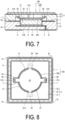
- FIG. 7 is a schematic cross-sectional view taken along line VII-VII in FIG. 5 .
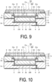
- FIG. 8 is a schematic plan view illustrating the battery package 1 according to another aspect of the first embodiment.
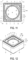
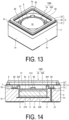
- FIGs. 9 and 10 are schematic cross-sectional views each illustrating the battery package according to another aspect of the first embodiment.
- the battery module 100 according to the first embodiment includes the battery package 1 according to the first embodiment and a battery 200 mounted on the battery package 1.
- the battery package 1 may include an insulation substrate 2, and the shape of the insulation substrate 2 in a plan view may be, for example, a rectangular shape.
- the insulation substrate 2 is made of, for example, a ceramic such as an aluminum oxide sintered body (alumina ceramic), an aluminum nitride sintered body, a mullite sintered body, or a glass ceramic sintered body.
- the insulation substrate 2 may include a plurality of insulating layers or a single insulating layer.
- the shape of the insulation substrate 2 in a plan view is not limited to a rectangular shape, and can be changed as appropriate.
- the insulation substrate 2 may have a first surface 2a, a second surface 2b located on the opposite side to the first surface 2a, and a plurality of side surfaces 2c located between the first surface 2a and the second surface 2b.
- the first surface 2a of the insulation substrate 2 may be a flat surface or may have irregularities.
- the second surface 2b of the insulation substrate 2 may be a flat surface or may have irregularities.
- the insulation substrate 2 may have a recessed portion 21 for accommodating the battery 200, and the recessed portion 21 may be open to the first surface 2a.
- the shape of the recessed portion 21 of the insulation substrate 2 in a plan view may be, for example, a circular shape.
- An inner side surface of the recessed portion 21 of the insulation substrate 2 may be parallel to the thickness direction of the insulation substrate 2.
- the size of the recessed portion 21 of the insulation substrate 2 in a plan view may be slightly larger than the size of a battery 200 in a plan view.
- the depth of the recessed portion 21 of the insulation substrate 2 may be substantially the same as the thickness of the battery 200.
- the shape of the recessed portion 21 of the insulation substrate 2 in a plan view is not limited to a circular shape, and may be changed according to the shape of the battery 200 in a plan view.
- the size of the inner side surface of the insulating frame body 31 in a plan view may be slightly larger than the size of the recessed portion 21 of the insulation substrate 2 in a plan view.
- the shape of the inner side surface of the insulating frame body 31 in a plan view is not limited to the rectangular shape, and may be changed according to the shape of the recessed portion 21 of the insulation substrate 2 in a plan view, the shape or arrangement of a second electrode 7 which will be described later, and the shape or arrangement of recessed step portions 31d which will be described later.
- the insulating frame body 31 may have a plurality of recessed step portions 31d as receiving portions, and the plurality of recessed step portions 31d may be located on the inner side surface of the insulating frame body 31.
- the plurality of recessed step portions 31d of the insulating frame body 31 may be arranged rotationally symmetrically with respect to the center of the insulating frame body 31.
- the number of the recessed step portions 31d serving as receiving portions is two, but may be three or more.
- an annular recessed step portion (not illustrated) may be located on the inner side surface of the insulating frame body 31.
- the frame portion 3 may include a frame-shaped metal film 32 located on the upper surface of the insulating frame body 31 so as to surround the opening side of the insulating frame body 31.
- the frame-shaped metal film 32 may be bonded to the upper surface of the insulating frame body 31.
- the frame-shaped metal film 32 is made of metallized metal powder containing tungsten (W), molybdenum (Mo), manganese (Mn), silver (Ag), copper (Cu), or the like as a component.
- the battery module 100A according to the second embodiment includes the battery package 1A according to the second embodiment and the battery 200 accommodated in the recessed portion 21 of the insulation substrate 2 of the battery package 1A.
- the lower surface electrode 201 of the battery 200 may be electrically connected to the first electrode 6.
- the upper surface electrode 202 of the battery 200 may be electrically connected to the conductive metal plate 8. Since the first external electrode 4 and the second external electrode 5 are located on the second surface 2b of the insulation substrate 2, the battery package 1A and the battery module 100A can be surface-mounted on a mounting substrate.
- each connecting piece 82 is bent in an arc shape, even when the front end side of the connecting piece 82 comes into contact with the inner side surface of the insulating frame body 31, the front end side of the connecting piece 82 is not caught, and each connecting piece 82 can be easily connected electrically to a corresponding one of the second electrodes 7 from above.
- the assemblability of the battery module 100A can be further improved.
- the insulating frame body 31 may have a plurality of insertion ports 31i which are open to the upper side and to the recessed portion 21 side of the insulation substrate 2. Each insertion port 31i of the insulating frame body 31 may be connected to a corresponding one of the recessed step portions 31d.
- each locking piece 83 can be inserted into a corresponding one of the insertion ports 31i of the insulating frame body 31, and each locking piece 83 can be easily locked from below to a corresponding one of the recessed step portions 31d of the insulating frame body 31.
- the assemblability (manufacturability) of the battery module 100A can be further improved.
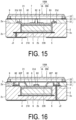
- FIG. 21 is a schematic plan view illustrating a battery package and a battery module according to the second variation of the second embodiment.
- FIG. 22 is a schematic cross-sectional view taken along line XXII-XXII in FIG. 21 .
- the insulating frame body 31 may have four inner corner portions 31C on the inner side surface thereof.
- the four inner corner portions 31C may be arranged rotationally symmetrically with respect to the center of the insulating frame body 31.
- the number of the recessed step portions 31d may be four.
- the number of the second electrodes 7 may be four.
- the number of the connecting pieces 82 and the number of the locking pieces 83 may be four.
- the number of the recessed step portions 31d, the number of the second electrodes 7, the number of the connecting pieces 82, and the number of the locking pieces 83 are each not limited to four, and may be three or five or more.
- the contact area between the second electrodes 7 and the connecting pieces 82 increases, providing a low resistance connection between the second electrodes 7 and the conductive metal plate 8.
- the electric power of the battery 200 can be more efficiently extracted.
- the conductive metal plate 8 can use its elastic force to uniformly press the battery 200 with an increased force to the bottom surface side of the recessed portion 21 of the insulation substrate 2.
- the fixing force that fixes the battery 200 to the bottom portion of the recessed portion 21 of the insulation substrate 2 can be increased, thus improving the long-term reliability of the battery module 100A.
- the connectivity between the lower surface electrode 201 of the battery 200 and the first electrode 6 can be enhanced, whereby the electric power of the battery 200 can be extracted more efficiently.
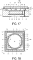
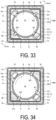
- FIG. 23 is a schematic plan view illustrating the battery package 1B and the battery module 100B according to the third embodiment.
- FIG. 24 is a schematic cross-sectional view taken along line XXIV-XXIV in FIG. 23 .
- FIG. 25 is a schematic cross-sectional view taken along line XXV-XXV in FIG. 24 .
- FIG. 26 is a schematic cross-sectional view illustrating the battery package 1B according to another aspect of the third embodiment.
- the battery module 100B according to the third embodiment includes the battery package 1B according to the third embodiment and the battery 200 mounted on the battery package 1B.
- the battery package 1B according to the third embodiment has the same configuration as the battery package 1A according to the second embodiment except for a part of the configuration.
- configurations of the battery package 1B according to the third embodiment configurations that are different from those of the battery package 1A according to the second embodiment will be described.
- members having the same functions as the members described in the first and second embodiments are denoted by the same reference signs.
- the insulating frame body 31 may have four inner corner portions 31C on the inner surface thereof.
- the four inner corner portions 31C may be arranged rotationally symmetrically with respect to the center of the insulating frame body 31.
- the recessed portion 21 of the insulation substrate 2 may have a plurality of recessed step portions 21d as receiving portions, and the plurality of recessed step portions 21d may be located on the inner side surface of the recessed portion 21 of the insulation substrate 2.
- the plurality of recessed step portions 21d may be arranged rotationally symmetrically with respect to the center of the recessed portion 21 of the insulation substrate 2.
- the number of the recessed step portions 21d is two, but may be three or more.
- an annular recessed step portion may be provided.
- each locking piece 83 of the conductive metal plate 8 may be locked to a corresponding one of the recessed step portions 21d of the insulation substrate 2 from below.
- the insulation substrate 2 may have a second cutout portion 22 on the upper side of each recessed step portion 21d.
- the plurality of second cutout portions 22 may be arranged rotationally symmetrically with respect to the center of the recessed portion 21 of the insulation substrate 2.
- a part of each locking piece 83 of the conductive metal plate 8 may overlap a corresponding one of the second cutout portions 22 of the insulation substrate 2 in a plan view.
- the second cutout portions 22 may be omitted from the configuration of the insulation substrate 2.
- the insulation substrate 2 having the recessed portion 21 and the plurality of second cutout portions 22 is formed by punching a ceramic green sheet for the insulating layer.
- each locking piece 83 of the conductive metal plate 8 is locked to a corresponding one of the recessed step portions 21d of the recessed portion 21 of the insulation substrate 2 from below, allowing the conductive metal plate 8 to press the battery 200 to the bottom surface side of the recessed portion 21 of the insulation substrate 2 by the elastic force. This allows the battery 200 to be mechanically fixed to the bottom portion of the recessed portion 21 of the insulation substrate 2.
- the insulating frame body 31 and the metal frame body 33 may be omitted from the configuration of the frame portion 3. In this case, the thickness of the battery package 1B and the battery module 100B can be reduced.
- the battery package 1B may include a lid 9B having a cap shape to close the opening of the frame portion 3.
- the lid 9B may be bonded to the frame-shaped metal film 32 which is the frame portion 3.
- the lid 9B may be electrically insulated from the conductive metal plate 8.
- the lid 9B is made of, for example, a metal having a small difference in thermal expansion coefficient from a ceramic such as an iron-nickel (Fe-Ni) alloy or an iron-nickel-cobalt (Fe-Ni-Co) alloy is used.
- the lid 9B may also be made of a ceramic instead of a metal.
- the lid 9B can be produced by pressing a metal plate.
- a laminate of ceramic green sheets may be fired in the same manner as the insulation substrate 2, or ceramic powder may be press-molded into a cap shape and then fired.
- determination on whether the battery module 100B is a non-defective product or a defective product can be performed easily by visual inspection, thus eliminating the concern of unexpectedly producing a defective product.
- the receiving portion may be provided as a plurality of recessed step portions or an annular recessed step portion located on an inner side surface of the recessed portion, and the conductive metal plate may have, on the peripheral portion thereof, a plurality of locking pieces locked to the recessed step portions from below as the locking portion.
- a battery module includes the battery package according to any one of (1) to (16), and a battery accommodated in the recessed portion of the battery package and including a lower surface electrode electrically connected to the first electrode and an upper surface electrode electrically connected to the conductive metal plate.
- the battery may be an all-solid-state battery in which a negative electrode layer, an electrolyte layer, and a positive electrode layer are layered.
- the battery may be a coin battery.
Landscapes
- Chemical & Material Sciences (AREA)
- Electrochemistry (AREA)
- General Chemical & Material Sciences (AREA)
- Chemical Kinetics & Catalysis (AREA)
- Engineering & Computer Science (AREA)
- Manufacturing & Machinery (AREA)
- Physics & Mathematics (AREA)
- Condensed Matter Physics & Semiconductors (AREA)
- General Physics & Mathematics (AREA)
- Inorganic Chemistry (AREA)
- Materials Engineering (AREA)
- Sealing Battery Cases Or Jackets (AREA)
- Battery Mounting, Suspending (AREA)
Applications Claiming Priority (2)
| Application Number | Priority Date | Filing Date | Title |
|---|---|---|---|
| JP2022137684 | 2022-08-31 | ||
| PCT/JP2023/029840 WO2024048326A1 (ja) | 2022-08-31 | 2023-08-18 | 電池用パッケージおよび電池モジュール |
Publications (1)
| Publication Number | Publication Date |
|---|---|
| EP4583268A1 true EP4583268A1 (en) | 2025-07-09 |
Family
ID=90099670
Family Applications (1)
| Application Number | Title | Priority Date | Filing Date |
|---|---|---|---|
| EP23860089.4A Pending EP4583268A1 (en) | 2022-08-31 | 2023-08-18 | Battery package, and battery module |
Country Status (5)
| Country | Link |
|---|---|
| US (1) | US20260088335A1 (https=) |
| EP (1) | EP4583268A1 (https=) |
| JP (1) | JP7753560B2 (https=) |
| CN (1) | CN119790531A (https=) |
| WO (1) | WO2024048326A1 (https=) |
Families Citing this family (3)
| Publication number | Priority date | Publication date | Assignee | Title |
|---|---|---|---|---|
| WO2025258331A1 (ja) * | 2024-06-10 | 2025-12-18 | マクセル株式会社 | 蓋体、全固体電池用容器及び全固体電池 |
| WO2026053782A1 (ja) * | 2024-09-06 | 2026-03-12 | パナソニックIpマネジメント株式会社 | 固体電池 |
| CN119833769A (zh) * | 2024-12-26 | 2025-04-15 | 广州融捷能源科技有限公司 | 扣式电池及其制造方法 |
Family Cites Families (4)
| Publication number | Priority date | Publication date | Assignee | Title |
|---|---|---|---|---|
| US4043113A (en) * | 1976-03-25 | 1977-08-23 | Hughes Aircraft Company | Electric watch battery retainer |
| JP2603688Y2 (ja) * | 1992-04-24 | 2000-03-15 | 東芝電池株式会社 | コイン形電池用ホルダ |
| JP5742503B2 (ja) | 2010-08-27 | 2015-07-01 | セイコーインスツル株式会社 | 電気化学セル |
| WO2022030424A1 (ja) | 2020-08-07 | 2022-02-10 | 京セラ株式会社 | 電池用パッケージおよび電池モジュール |
-
2023
- 2023-08-18 EP EP23860089.4A patent/EP4583268A1/en active Pending
- 2023-08-18 US US19/106,874 patent/US20260088335A1/en active Pending
- 2023-08-18 CN CN202380062302.9A patent/CN119790531A/zh active Pending
- 2023-08-18 JP JP2024544135A patent/JP7753560B2/ja active Active
- 2023-08-18 WO PCT/JP2023/029840 patent/WO2024048326A1/ja not_active Ceased
Also Published As
| Publication number | Publication date |
|---|---|
| WO2024048326A1 (ja) | 2024-03-07 |
| US20260088335A1 (en) | 2026-03-26 |
| CN119790531A (zh) | 2025-04-08 |
| JPWO2024048326A1 (https=) | 2024-03-07 |
| JP7753560B2 (ja) | 2025-10-14 |
Similar Documents
| Publication | Publication Date | Title |
|---|---|---|
| EP4583268A1 (en) | Battery package, and battery module | |
| TWI794921B (zh) | 電池用封裝體及電池模組 | |
| US12009285B2 (en) | Substrate having a recessed portion for an electronic component | |
| US20250118841A1 (en) | Battery package and battery module | |
| JP2005072421A (ja) | 電子部品収納用パッケージおよび電子装置 | |
| JP2012174713A (ja) | 電子部品収納用パッケージ、およびそれを備えた電子装置 | |
| JP3866128B2 (ja) | 配線基板 | |
| JP3950950B2 (ja) | セラミック配線基板の製造方法 | |
| JP2012009687A (ja) | 赤外線センサ素子用パッケージおよび赤外線センサ | |
| JP2541762Y2 (ja) | 半導体素子収納用パッケージ | |
| JP2508243Y2 (ja) | 混成集積回路装置 | |
| JP2004022957A (ja) | 電子部品搭載用基板 | |
| JP2878046B2 (ja) | 電子部品収納用パッケージ | |
| JP3020783B2 (ja) | 半導体素子収納用パッケージ | |
| JP2005243969A (ja) | 撮像装置 | |
| JP2004147110A (ja) | 圧電振動子収納用パッケージ | |
| JPH02143539A (ja) | 半導体素子収納用パッケージ | |
| JP2006185978A (ja) | 複数個取り配線基板 | |
| JP2000340704A (ja) | 半導体素子収納用パッケージ | |
| JPH08316363A (ja) | 半導体素子収納用パッケージ | |
| JP2002164451A (ja) | 電子部品収納用パッケージ | |
| JP2005072393A (ja) | 配線基板 | |
| JPH04111749U (ja) | 半導体素子収納用パツケージ | |
| JP2003068932A (ja) | 配線基板 | |
| JP2001210738A (ja) | 電子部品収納用パッケージ |
Legal Events
| Date | Code | Title | Description |
|---|---|---|---|
| STAA | Information on the status of an ep patent application or granted ep patent |
Free format text: STATUS: THE INTERNATIONAL PUBLICATION HAS BEEN MADE |
|
| PUAI | Public reference made under article 153(3) epc to a published international application that has entered the european phase |
Free format text: ORIGINAL CODE: 0009012 |
|
| STAA | Information on the status of an ep patent application or granted ep patent |
Free format text: STATUS: REQUEST FOR EXAMINATION WAS MADE |
|
| 17P | Request for examination filed |
Effective date: 20250225 |
|
| AK | Designated contracting states |
Kind code of ref document: A1 Designated state(s): AL AT BE BG CH CY CZ DE DK EE ES FI FR GB GR HR HU IE IS IT LI LT LU LV MC ME MK MT NL NO PL PT RO RS SE SI SK SM TR |
|
| DAV | Request for validation of the european patent (deleted) | ||
| DAX | Request for extension of the european patent (deleted) |