EP4583267A1 - Secondary battery and electronic apparatus comprising same - Google Patents
Secondary battery and electronic apparatus comprising same Download PDFInfo
- Publication number
- EP4583267A1 EP4583267A1 EP22959153.2A EP22959153A EP4583267A1 EP 4583267 A1 EP4583267 A1 EP 4583267A1 EP 22959153 A EP22959153 A EP 22959153A EP 4583267 A1 EP4583267 A1 EP 4583267A1
- Authority
- EP
- European Patent Office
- Prior art keywords
- insulating adhesive
- adhesive layer
- thickness
- secondary battery
- sealing
- Prior art date
- Legal status (The legal status is an assumption and is not a legal conclusion. Google has not performed a legal analysis and makes no representation as to the accuracy of the status listed.)
- Pending
Links
Images


Classifications
-
- H—ELECTRICITY
- H01—ELECTRIC ELEMENTS
- H01M—PROCESSES OR MEANS, e.g. BATTERIES, FOR THE DIRECT CONVERSION OF CHEMICAL ENERGY INTO ELECTRICAL ENERGY
- H01M50/00—Constructional details or processes of manufacture of the non-active parts of electrochemical cells other than fuel cells, e.g. hybrid cells
- H01M50/10—Primary casings; Jackets or wrappings
- H01M50/102—Primary casings; Jackets or wrappings characterised by their shape or physical structure
- H01M50/105—Pouches or flexible bags
-
- H—ELECTRICITY
- H01—ELECTRIC ELEMENTS
- H01M—PROCESSES OR MEANS, e.g. BATTERIES, FOR THE DIRECT CONVERSION OF CHEMICAL ENERGY INTO ELECTRICAL ENERGY
- H01M50/00—Constructional details or processes of manufacture of the non-active parts of electrochemical cells other than fuel cells, e.g. hybrid cells
- H01M50/50—Current conducting connections for cells or batteries
- H01M50/531—Electrode connections inside a battery casing
- H01M50/534—Electrode connections inside a battery casing characterised by the material of the leads or tabs
-
- H—ELECTRICITY
- H01—ELECTRIC ELEMENTS
- H01M—PROCESSES OR MEANS, e.g. BATTERIES, FOR THE DIRECT CONVERSION OF CHEMICAL ENERGY INTO ELECTRICAL ENERGY
- H01M50/00—Constructional details or processes of manufacture of the non-active parts of electrochemical cells other than fuel cells, e.g. hybrid cells
- H01M50/10—Primary casings; Jackets or wrappings
- H01M50/172—Arrangements of electric connectors penetrating the casing
- H01M50/174—Arrangements of electric connectors penetrating the casing adapted for the shape of the cells
- H01M50/178—Arrangements of electric connectors penetrating the casing adapted for the shape of the cells for pouch or flexible bag cells
-
- H—ELECTRICITY
- H01—ELECTRIC ELEMENTS
- H01M—PROCESSES OR MEANS, e.g. BATTERIES, FOR THE DIRECT CONVERSION OF CHEMICAL ENERGY INTO ELECTRICAL ENERGY
- H01M50/00—Constructional details or processes of manufacture of the non-active parts of electrochemical cells other than fuel cells, e.g. hybrid cells
- H01M50/10—Primary casings; Jackets or wrappings
- H01M50/183—Sealing members
- H01M50/184—Sealing members characterised by their shape or structure
-
- H—ELECTRICITY
- H01—ELECTRIC ELEMENTS
- H01M—PROCESSES OR MEANS, e.g. BATTERIES, FOR THE DIRECT CONVERSION OF CHEMICAL ENERGY INTO ELECTRICAL ENERGY
- H01M50/00—Constructional details or processes of manufacture of the non-active parts of electrochemical cells other than fuel cells, e.g. hybrid cells
- H01M50/10—Primary casings; Jackets or wrappings
- H01M50/183—Sealing members
- H01M50/186—Sealing members characterised by the disposition of the sealing members
-
- H—ELECTRICITY
- H01—ELECTRIC ELEMENTS
- H01M—PROCESSES OR MEANS, e.g. BATTERIES, FOR THE DIRECT CONVERSION OF CHEMICAL ENERGY INTO ELECTRICAL ENERGY
- H01M50/00—Constructional details or processes of manufacture of the non-active parts of electrochemical cells other than fuel cells, e.g. hybrid cells
- H01M50/10—Primary casings; Jackets or wrappings
- H01M50/183—Sealing members
- H01M50/19—Sealing members characterised by the material
- H01M50/193—Organic material
-
- H—ELECTRICITY
- H01—ELECTRIC ELEMENTS
- H01M—PROCESSES OR MEANS, e.g. BATTERIES, FOR THE DIRECT CONVERSION OF CHEMICAL ENERGY INTO ELECTRICAL ENERGY
- H01M50/00—Constructional details or processes of manufacture of the non-active parts of electrochemical cells other than fuel cells, e.g. hybrid cells
- H01M50/10—Primary casings; Jackets or wrappings
- H01M50/183—Sealing members
- H01M50/19—Sealing members characterised by the material
- H01M50/197—Sealing members characterised by the material having a layered structure
-
- H—ELECTRICITY
- H01—ELECTRIC ELEMENTS
- H01M—PROCESSES OR MEANS, e.g. BATTERIES, FOR THE DIRECT CONVERSION OF CHEMICAL ENERGY INTO ELECTRICAL ENERGY
- H01M50/00—Constructional details or processes of manufacture of the non-active parts of electrochemical cells other than fuel cells, e.g. hybrid cells
- H01M50/10—Primary casings; Jackets or wrappings
- H01M50/183—Sealing members
- H01M50/19—Sealing members characterised by the material
- H01M50/198—Sealing members characterised by the material characterised by physical properties, e.g. adhesiveness or hardness
-
- H—ELECTRICITY
- H01—ELECTRIC ELEMENTS
- H01M—PROCESSES OR MEANS, e.g. BATTERIES, FOR THE DIRECT CONVERSION OF CHEMICAL ENERGY INTO ELECTRICAL ENERGY
- H01M50/00—Constructional details or processes of manufacture of the non-active parts of electrochemical cells other than fuel cells, e.g. hybrid cells
- H01M50/50—Current conducting connections for cells or batteries
- H01M50/531—Electrode connections inside a battery casing
- H01M50/533—Electrode connections inside a battery casing characterised by the shape of the leads or tabs
-
- H—ELECTRICITY
- H01—ELECTRIC ELEMENTS
- H01M—PROCESSES OR MEANS, e.g. BATTERIES, FOR THE DIRECT CONVERSION OF CHEMICAL ENERGY INTO ELECTRICAL ENERGY
- H01M50/00—Constructional details or processes of manufacture of the non-active parts of electrochemical cells other than fuel cells, e.g. hybrid cells
- H01M50/50—Current conducting connections for cells or batteries
- H01M50/543—Terminals
- H01M50/552—Terminals characterised by their shape
- H01M50/553—Terminals adapted for prismatic, pouch or rectangular cells
- H01M50/557—Plate-shaped terminals
-
- H—ELECTRICITY
- H01—ELECTRIC ELEMENTS
- H01M—PROCESSES OR MEANS, e.g. BATTERIES, FOR THE DIRECT CONVERSION OF CHEMICAL ENERGY INTO ELECTRICAL ENERGY
- H01M2220/00—Batteries for particular applications
- H01M2220/30—Batteries in portable systems, e.g. mobile phone, laptop
-
- H—ELECTRICITY
- H01—ELECTRIC ELEMENTS
- H01M—PROCESSES OR MEANS, e.g. BATTERIES, FOR THE DIRECT CONVERSION OF CHEMICAL ENERGY INTO ELECTRICAL ENERGY
- H01M50/00—Constructional details or processes of manufacture of the non-active parts of electrochemical cells other than fuel cells, e.g. hybrid cells
- H01M50/10—Primary casings; Jackets or wrappings
- H01M50/116—Primary casings; Jackets or wrappings characterised by the material
- H01M50/117—Inorganic material
- H01M50/119—Metals
-
- H—ELECTRICITY
- H01—ELECTRIC ELEMENTS
- H01M—PROCESSES OR MEANS, e.g. BATTERIES, FOR THE DIRECT CONVERSION OF CHEMICAL ENERGY INTO ELECTRICAL ENERGY
- H01M50/00—Constructional details or processes of manufacture of the non-active parts of electrochemical cells other than fuel cells, e.g. hybrid cells
- H01M50/50—Current conducting connections for cells or batteries
- H01M50/543—Terminals
- H01M50/547—Terminals characterised by the disposition of the terminals on the cells
- H01M50/55—Terminals characterised by the disposition of the terminals on the cells on the same side of the cell
Definitions
- This application relates to the field of energy storage apparatuses, and in particular, to a secondary battery and an electronic apparatus including such battery.
- Lithium-ion secondary batteries have been widely used in the fields such as electrical energy storage, portable electronic devices, and electric vehicles, due to their characteristics such as high energy density, long cycle life, high nominal voltage, low self-discharge rate, small volume, and light weight.
- lithium-ion secondary batteries before leaving factory, need to be subjected to a series of tests, including an internal short-circuit test, a drop test, a puncture test, and the like.
- the drop test is a stringent safety test for lithium-ion secondary batteries. After drop, issues such as a top seal being burst open and electrolyte leakage are likely to occur at tabs of a lithium-ion secondary battery.
- insulating adhesives are typically applied at tab sealing positions to improve the sealing effect. However, the sealing effect between the existing insulating adhesives and the housing still needs improvement.
- An objective of this application is to provide a secondary battery that can enhance sealing strength at tabs, and an electronic apparatus including such secondary battery.
- a first aspect of this application provides a secondary battery, including an electrode assembly, a tab assembly, and a packaging pouch.
- the electrode assembly is accommodated in the packaging pouch.
- the packaging pouch includes a sealing portion
- the tab assembly includes tabs and insulating adhesives respectively disposed on two sides of each tab, and the tabs are connected to the electrode assembly and run through the sealing portion to extend out of the packaging pouch.
- the insulating adhesives connect the tabs and the packaging pouch.
- the insulating adhesive includes a first insulating adhesive layer, a second insulating adhesive layer, and a third insulating adhesive layer sequentially stacked in a first direction, the first insulating adhesive layer is connected to the tab, and the third insulating adhesive layer is connected to the packaging pouch.
- the insulating adhesive includes a first part, where the first part is a region where at which the insulating adhesive overlaps the tab in the first direction and is not overlap the sealing portion.
- a thickness of the insulating adhesive is h1
- a thickness of the first insulating adhesive layer is A1
- a thickness of the second insulating adhesive layer is B1
- a thickness of the third insulating adhesive layer is C1, where 10.5%h1 ⁇ B1 ⁇ 35%h1, 90%B1 ⁇ C1 ⁇ 500%B1, C1>A1, and 60%B1 ⁇ A1 ⁇ 400%B1.
- 10.5%h1 ⁇ B1 ⁇ 35%h1 ensures that the second insulating adhesive layer does not over-melt or insufficiently fuse during heat sealing, preventing interfaces and delamination between the second insulating adhesive layer and the first insulating adhesive layer as well as the third insulating adhesive layer, thereby preventing sealing strength reduction.
- 90%B1 ⁇ C1 ⁇ 500%B1, 60%B1 ⁇ A1 ⁇ 400%B1, and C1>A1 ensure that the third insulating adhesive layer can fully fuse with the packaging pouch, and the first insulating adhesive layer can fuse to be bonded to the tab.
- the third insulating adhesive layer is heated to melt before the first insulating adhesive layer during sealing.
- This design can prevent the third insulation adhesive layer from over-melting, where such over-melting causes fusion between the packaging pouch and the second insulation adhesive layer, thereby avoiding poor fusion interfaces, and can also prevent poor bonding with the tab caused by the first insulating adhesive layer fusing insufficiently or over-melting.
- the first insulating adhesive layer, the second insulating adhesive layer, and the third insulating adhesive layer are asymmetrical in thickness. With the use of this three-layer structure with asymmetrical thickness, during sealing, the insulating adhesive and the packaging pouch can fully fuse without noticeable interfaces, thereby enhancing the sealing strength between the insulating adhesive and the packaging pouch, improving the sealing effect, and reducing a risk of electrolyte leakage.
- a sealing tensile force is greater than or equal to 5.75 N.
- the sealing tensile force after sealing increases and a resulting secondary battery 100 is less prone to electrolyte leakage.
- insufficient melting and interface issues occur between the third insulating adhesive layer, the sealing layer, and the second insulating adhesive layer during sealing, reducing the sealing tensile force and increasing the risk of electrolyte leakage in the secondary battery 100.
- the sealing tensile force is greater than or equal to 6.2 N, such that the resulting secondary battery 100 after sealing is less prone to electrolyte leakage.
- the insulating adhesive in the second direction, further includes a second part, and the second part is a region at which the insulating adhesive overlaps the sealing portion in the first direction.
- the insulating adhesive includes a second part of first insulating adhesive layer, a second part of second insulating adhesive layer, and a second part of third insulating adhesive layer sequentially stacked in the first direction, and in the first direction, thicknesses of the second part of first insulating adhesive layer, the second part of second insulating adhesive layer, and the second part of third insulating adhesive layer are A2, B2, and C2, respectively.
- a thickness of the second part of third insulating adhesive layer in the first direction is C2, and 92%C1 ⁇ C2 ⁇ 98%C1.
- the packaging pouch includes a sealing layer connected to the third insulating adhesive layer, and a thickness of the sealing layer in the first direction is P; and in the second part, a total thickness of the second part of third insulating adhesive layer and the sealing layer in the first direction is H, where 0.25(C2+P) ⁇ H ⁇ 0.75(C2+P).
- a thickness of the second part of first insulating adhesive layer in the first direction is A2, and A1 and A2 satisfy the following formula: 5 ⁇ m ⁇ A1-A2 ⁇ 0.5 ⁇ m.
- a thickness of the second part of second insulating adhesive layer in the first direction is B2, and B1 and B2 satisfy the following formula: 3 ⁇ m ⁇ B1-B2 ⁇ 0.1 ⁇ m.
- the packaging pouch includes a sealing layer connected to the third insulating adhesive layer, and in the first direction, a thickness of the packaging pouch is T and a thickness of the sealing layer is P; and in the first direction, a thickness of a part of the tab assembly corresponding to the second part is G and a thickness of a part of the secondary battery corresponding to the second part and the tab is K, where 2T+G-(2P+2t) ⁇ 75% ⁇ K ⁇ 2T+G-(2P+2t) ⁇ 15%.
- a thickness of the insulating adhesive is h3, a thickness of the first insulating adhesive layer is A3, a thickness of the second insulating adhesive layer is B3, and a thickness of the third insulating adhesive layer is C3, where 10.5%h3 ⁇ B3 ⁇ 35%h3, C3>A3, 90%B3 ⁇ C3 ⁇ 500%B3, and 60%B3 ⁇ A3 ⁇ 400%B3.
- the tab assembly includes a bonding region, and the bonding region is a part at which the insulating adhesives on two sides of the tab adhere to each other in the first direction; and in the first direction, the bonding region includes a bonding region first insulating adhesive bonding layer, a bonding region second insulating adhesive layer, and a bonding region third insulating adhesive layer, a thickness of the bonding region is Q, a thickness of the bonding region first insulating adhesive bonding layer is D, a thickness of the bonding region second insulating adhesive layer is B4, and a thickness of the bonding region third insulating adhesive layer is C4, where 10.5%(Q ⁇ 0.5) ⁇ B4 ⁇ 35%(Q ⁇ 0.5), C4>0.5D, 90%B4 ⁇ C4 ⁇ 500%B4, and 120%B4 ⁇ D ⁇ 800%B4.
- the first insulating adhesive layer and/or the third insulating adhesive layer further includes a toughening modifier.
Landscapes
- Chemical & Material Sciences (AREA)
- Chemical Kinetics & Catalysis (AREA)
- Electrochemistry (AREA)
- General Chemical & Material Sciences (AREA)
- Sealing Battery Cases Or Jackets (AREA)
Abstract
Description
- This application relates to the field of energy storage apparatuses, and in particular, to a secondary battery and an electronic apparatus including such battery.
- Lithium-ion secondary batteries have been widely used in the fields such as electrical energy storage, portable electronic devices, and electric vehicles, due to their characteristics such as high energy density, long cycle life, high nominal voltage, low self-discharge rate, small volume, and light weight. To ensure the safety performance of secondary batteries, lithium-ion secondary batteries, before leaving factory, need to be subjected to a series of tests, including an internal short-circuit test, a drop test, a puncture test, and the like. The drop test is a stringent safety test for lithium-ion secondary batteries. After drop, issues such as a top seal being burst open and electrolyte leakage are likely to occur at tabs of a lithium-ion secondary battery. Currently, insulating adhesives are typically applied at tab sealing positions to improve the sealing effect. However, the sealing effect between the existing insulating adhesives and the housing still needs improvement.
- An objective of this application is to provide a secondary battery that can enhance sealing strength at tabs, and an electronic apparatus including such secondary battery.
- A first aspect of this application provides a secondary battery, including an electrode assembly, a tab assembly, and a packaging pouch. The electrode assembly is accommodated in the packaging pouch. The packaging pouch includes a sealing portion, the tab assembly includes tabs and insulating adhesives respectively disposed on two sides of each tab, and the tabs are connected to the electrode assembly and run through the sealing portion to extend out of the packaging pouch. The insulating adhesives connect the tabs and the packaging pouch. The insulating adhesive includes a first insulating adhesive layer, a second insulating adhesive layer, and a third insulating adhesive layer sequentially stacked in a first direction, the first insulating adhesive layer is connected to the tab, and the third insulating adhesive layer is connected to the packaging pouch. In a second direction perpendicular to the first direction, the insulating adhesive includes a first part, where the first part is a region where at which the insulating adhesive overlaps the tab in the first direction and is not overlap the sealing portion. In the first end portion, in the first direction, a thickness of the insulating adhesive is h1, a thickness of the first insulating adhesive layer is A1, a thickness of the second insulating adhesive layer is B1, and a thickness of the third insulating adhesive layer is C1, where 10.5%h1≤B1≤35%h1, 90%B1≤C1≤500%B1, C1>A1, and 60%B1≤A1≤400%B1.
- In the secondary battery provided in this application, 10.5%h1≤B1≤35%h1 ensures that the second insulating adhesive layer does not over-melt or insufficiently fuse during heat sealing, preventing interfaces and delamination between the second insulating adhesive layer and the first insulating adhesive layer as well as the third insulating adhesive layer, thereby preventing sealing strength reduction. 90%B1≤C1≤500%B1, 60%B1≤A1≤400%B1, and C1>A1 ensure that the third insulating adhesive layer can fully fuse with the packaging pouch, and the first insulating adhesive layer can fuse to be bonded to the tab. The third insulating adhesive layer is heated to melt before the first insulating adhesive layer during sealing. This design can prevent the third insulation adhesive layer from over-melting, where such over-melting causes fusion between the packaging pouch and the second insulation adhesive layer, thereby avoiding poor fusion interfaces, and can also prevent poor bonding with the tab caused by the first insulating adhesive layer fusing insufficiently or over-melting. In addition, the first insulating adhesive layer, the second insulating adhesive layer, and the third insulating adhesive layer are asymmetrical in thickness. With the use of this three-layer structure with asymmetrical thickness, during sealing, the insulating adhesive and the packaging pouch can fully fuse without noticeable interfaces, thereby enhancing the sealing strength between the insulating adhesive and the packaging pouch, improving the sealing effect, and reducing a risk of electrolyte leakage.
- According to some embodiments of this application, 8.18A1≥C1≥1.05A1, and a sealing tensile force is greater than or equal to 5.75 N. As the thickness of the third insulating adhesive layer increases, the sealing tensile force after sealing increases and a resulting
secondary battery 100 is less prone to electrolyte leakage. In a case of 8.18A1<C1, insufficient melting and interface issues occur between the third insulating adhesive layer, the sealing layer, and the second insulating adhesive layer during sealing, reducing the sealing tensile force and increasing the risk of electrolyte leakage in thesecondary battery 100. Preferably, 7A1≥C1≥1.3A1. Within this range, the sealing tensile force is greater than or equal to 6.2 N, such that the resultingsecondary battery 100 after sealing is less prone to electrolyte leakage. - According to some embodiments of this application, the thickness of the tab in the first direction is t, where 3t≥2h1≥0.9t.
- According to some embodiments of this application, in the second direction, the insulating adhesive further includes a second part, and the second part is a region at which the insulating adhesive overlaps the sealing portion in the first direction. In the second part, the insulating adhesive includes a second part of first insulating adhesive layer, a second part of second insulating adhesive layer, and a second part of third insulating adhesive layer sequentially stacked in the first direction, and in the first direction, thicknesses of the second part of first insulating adhesive layer, the second part of second insulating adhesive layer, and the second part of third insulating adhesive layer are A2, B2, and C2, respectively.
- According to some embodiments of this application, in the second part, a thickness of the second part of third insulating adhesive layer in the first direction is C2, and 92%C1≤C2≤98%C1.
- According to some embodiments of this application, 7 µm≥C1-C2≥1 µm.
- According to some embodiments of this application, the packaging pouch includes a sealing layer connected to the third insulating adhesive layer, and a thickness of the sealing layer in the first direction is P; and in the second part, a total thickness of the second part of third insulating adhesive layer and the sealing layer in the first direction is H, where 0.25(C2+P)≤H≤0.75(C2+P).
- According to some embodiments of this application, 0.4(C2+P)≤H≤0.7(C2+P).
- According to some embodiments of this application, in the second part, a thickness of the second part of first insulating adhesive layer in the first direction is A2, and A1 and A2 satisfy the following formula: 5 µm≥A1-A2≥0.5 µm.
- According to some embodiments of this application, in the second part, a thickness of the second part of second insulating adhesive layer in the first direction is B2, and B1 and B2 satisfy the following formula: 3 µm≥B1-B2≥0.1 µm.
- According to some embodiments of this application, the packaging pouch includes a sealing layer connected to the third insulating adhesive layer, and in the first direction, a thickness of the packaging pouch is T and a thickness of the sealing layer is P; and in the first direction, a thickness of a part of the tab assembly corresponding to the second part is G and a thickness of a part of the secondary battery corresponding to the second part and the tab is K, where 2T+G-(2P+2t)×75%<K<2T+G-(2P+2t)×15%.
- According to some embodiments of this application, in the second direction, the insulating adhesive further includes a third part; the third part is a region at which the insulating adhesive does not overlap the sealing portion or the tab in the first direction; and in the third part, in the first direction, the insulating adhesive includes a third part of first insulating adhesive layer, a third part of second insulating adhesive layer, and a third part of third insulating adhesive layer sequentially stacked in the first direction. A thickness of the insulating adhesive is h3, a thickness of the first insulating adhesive layer is A3, a thickness of the second insulating adhesive layer is B3, and a thickness of the third insulating adhesive layer is C3, where 10.5%h3≤B3≤35%h3, C3>A3, 90%B3≤C3≤500%B3, and 60%B3≤A3≤400%B3.
- According to some embodiments of this application, the tab assembly includes a bonding region, and the bonding region is a part at which the insulating adhesives on two sides of the tab adhere to each other in the first direction; and in the first direction, the bonding region includes a bonding region first insulating adhesive bonding layer, a bonding region second insulating adhesive layer, and a bonding region third insulating adhesive layer, a thickness of the bonding region is Q, a thickness of the bonding region first insulating adhesive bonding layer is D, a thickness of the bonding region second insulating adhesive layer is B4, and a thickness of the bonding region third insulating adhesive layer is C4, where 10.5%(Q×0.5)≤B4≤35%(Q×0.5), C4>0.5D, 90%B4≤C4≤500%B4, and 120%B4≤D≤800%B4.
- According to some embodiments of this application, melting points of the first insulating adhesive layer and the third insulating adhesive layer are 100-140°C, and a melting point of the second insulating adhesive layer is 140-200°C.
- According to some embodiments of this application, the first insulating adhesive layer, the second insulating adhesive layer, and the third insulating adhesive layer may each include one or more of polypropylene, polyethylene, poly(vinylidene difluoride), vinylidene fluoride-hexafluoropropylene copolymer, polymethyl methacrylate, or polyethylene glycol.
- According to some embodiments of this application, the first insulating adhesive layer and/or the third insulating adhesive layer further includes a toughening modifier.
- According to some embodiments of this application, the toughening modifier includes one or more of ethylene propylene rubber, ethylene propylene diene monomer rubber, styrene-butadiene rubber, low-density polyethylene, ethylene-vinyl acetate copolymer, linear low-density polyethylene, nylon, polyethylene terephthalate, polycarbonate, or ultra-high-molecular-weight polyethylene.
- According to some embodiments of this application, based on a total mass of the first insulating adhesive layer, a percentage of the toughening modifier is 3%-10%; and/or based on a total mass of the third insulating adhesive layer, a percentage of the toughening modifier is 3%-10%.
- According to some embodiments of this application, h1 is 30-160 µm.
- A second aspect of this application provides an electronic apparatus, including the foregoing secondary battery.
- The above and/or additional aspects and advantages of this application will become obvious and easy to understand from the description of some embodiments with reference to the following accompanying drawings.
-
FIG. 1 is a schematic diagram of a secondary battery according to an embodiment of this application; -
FIG. 2 is a schematic sectional view of the battery shown inFIG. 1 along II-II; -
FIG. 3 is a schematic sectional view of a sealing film according to an embodiment of this application; -
FIG. 4 is a schematic sectional view of an insulating adhesive according to an embodiment of this application; and -
FIG. 5 is a schematic diagram of an electronic apparatus according to an embodiment of this application. -
Secondary battery 100 Electrode assembly 10. Packaging pouch 40 Tab 20 Insulating adhesive 30 First sealing film 41 Second sealing film 42 Accommodating cavity 410 Sealing portion 420 Third part 301 Second part 302 First part 303 Sealing layer 401 Metal layer 402 Protective layer 403 First end portion 303a Second end portion 303b First insulating adhesive layer 31 Second insulating adhesive layer 32 Third insulating adhesive layer 33 Bonding region 201 Electronic apparatus 200 Main body 210 - The following clearly and detailly describes the technical solutions in some embodiments of this application. Apparently, the described embodiments are some rather than all embodiments of this application. Unless otherwise defined, all technical and scientific terms used herein shall have the same meanings as commonly understood by persons skilled in the art to which this application belongs. The terms used in the specification of this application are merely intended to describe specific embodiments rather than to limit this application.
- The following describes some embodiments of this application in detail. However, this application may be embodied in many different implementations and should not be construed as being limited to the example embodiments set forth herein. Rather, these example embodiments are provided such that this application can be conveyed to persons skilled in the art thoroughly and in detail.
- In addition, in the accompanying drawings, sizes or thicknesses of various components and layers may be exaggerated for brevity and clarity. Throughout the text, the same numerical values represent the same elements. As used herein, the term "and/or" includes any and all combinations of one or more associated items listed. In addition, it should be understood that when an element A is referred to as being "connected to" an element B, the element A may be directly connected to the element B, or an intervening element C may be present there between such that the element A and the element B are indirectly connected to each other.
- Further, the use of "may" for describing embodiments of this application relates to "one or more embodiments of this application."
- The technical terms used herein are merely intended to describe specific embodiments rather than to limit this application. As used herein, the singular forms are intended to include the plural forms as well, unless otherwise clearly indicated in the context. It should be further understood that the term "include" used in this specification indicates the presence of stated features, numerical values, steps, operations, elements, and/or components but does not preclude the presence or addition of one or more other features, numerical values, steps, operations, elements, components, and/or combinations thereof.
- Spatial related terms such as "above" may be used herein for ease of description to describe the relationship between one element or feature and another element (a plurality of elements) or feature (a plurality of features) as illustrated in the figure. It should be understood that the spatial related terms are intended to include different directions of a device or an apparatus in use or operation in addition to the directions described in the figures. For example, if the device in the figures is turned over, elements described as "over" or "above" other elements or features would then be oriented "beneath" or "below" the other elements or features. Thus, the example term "above" may include both directions of above and below. It should be understood that although the terms first, second, third, and the like may be used herein to describe various elements, components, regions, layers, and/or portions, these elements, components, regions, layers, and/or portions should not be limited by these terms. These terms are used to distinguish one element, component, region, layer, or portion from another element, component, region, layer, or portion. Therefore, the first element, component, region, layer, or portion discussed below may be referred to as the second element, component, region, layer, or portion without departing from the teachings of the example embodiments.
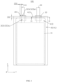
- Referring to
FIG. 1 andFIG. 2 , an embodiment of this application provides asecondary battery 100, including anelectrode assembly 10, a tab assembly, and apackaging pouch 40. The tab assembly includestabs 20 and two insulatingadhesives 30 respectively disposed on two sides of each tab. Thetabs 20 are connected to theelectrode assembly 10. Thepackaging pouch 40 covers theelectrode assembly 10 and part of thetab 20, and the insulatingadhesive 30 is disposed between thepackaging pouch 40 and thetab 20 and connects thepackaging pouch 40 and thetab 20. In this embodiment, twotabs 20 are provided, namely a positive tab and a negative tab. The twotabs 20 are located on the same side of thesecondary battery 100 and extend out of thepackaging pouch 40. Four insulatingadhesives 30 are provided, where two insulatingadhesives 30 are disposed on two opposite surfaces of onetab 20, the other two insulatingadhesives 30 are disposed on two opposite surfaces of theother tab 20, and the two insulatingadhesives 30 on the same side of the twotabs 20 are spaced apart. A material of the positive tab may include at least one of Ni, Ti, Al, Ag, Au, Pt, Fe, or a composition thereof. A material of the negative tab may include at least one of Ni, Ti, Cu, Ag, Au, Pt, Fe, or a composition thereof. In other embodiments, the two insulatingadhesives 30 on the same side of the twotabs 20 may be connected to form a whole, and the twotabs 20 may be alternatively located on different sides of thesecondary battery 100. - The
electrode assembly 10 includes a positive electrode plate, a negative electrode plate, and a separator configured between the positive electrode plate and the negative electrode plate. Theelectrode assembly 10 is formed by laminating or winding the positive electrode plate, the separator, and the negative electrode plate. The positive electrode plate and the negative electrode plate are electrically connected to the twotabs 20, respectively. - The
packaging pouch 40 includes afirst sealing film 41 and asecond sealing film 42 opposite each other, and a shape of thefirst sealing film 41 matches a shape of thesecond sealing film 42. Thefirst sealing film 41 and thesecond sealing film 42 are connected to each other and enclose anaccommodating cavity 410, and theaccommodating cavity 410 is used for accommodating an electrolyte, theelectrode assembly 10, thetabs 20, and at least part of the insulatingadhesive 30. Edges of thefirst sealing film 41 and thesecond sealing film 42 are connected to form a sealingportion 420, and the sealingportion 420 extends from an outer side surface of theaccommodating cavity 410 towards a side back away from theaccommodating cavity 410. The sealingportion 420 is part of thepackaging pouch 40 that is sealed through a hot pressing process after theelectrode assembly 10 and the electrolyte are accommodated therein. Thetab 20 is partially accommodated in theaccommodating cavity 410 and runs through the sealingportion 420 to extend out of thepackaging pouch 40. - Referring to
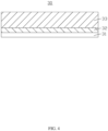
FIG. 2 andFIG. 3 , thefirst sealing film 41 and thesecond sealing film 42 each include asealing layer 401, ametal layer 402, and aprotective layer 403 sequentially stacked in first direction Z. Thesealing layer 401 is closer to theelectrode assembly 10 and theprotective layer 403 is farther from theelectrode assembly 10. A material of thesealing layer 401 is a polymer, such as polypropylene or polyamide. The sealing layers 401 of thefirst sealing film 41 and thesecond sealing film 42 are connected to seal thepackaging pouch 40, preventing thepackaging pouch 40 from being dissolved by an organic solvent in the electrolyte or swelling. Thesealing layer 401 is further configured to prevent themetal layer 402 from corrosion caused by an electrolytic salt in the electrolyte coming into contact with themetal layer 402. The material of theprotective layer 403 is a polymer resin, which is used to protect themetal layer 402, preventing damage to themetal layer 402 caused by action of an external force. This resin also prevents air from the external environment from penetrating, maintaining the interior of thesecondary battery 100 in a water-free and oxygen-free environment. The material of themetal layer 402 is metal, such as aluminum or steel, which is used to prevent moisture from the external environment from penetrating and to protect thesecondary battery 100 from damage caused by the external force. When thepackaging pouch 40 is used to package thesecondary battery 100, the sealing films can be folded, and then a heat-sealing head is used to perform heat sealing on surfaces of the folded sealing films under pressure (0.3-0.6 MPa) at a certain temperature (180-215°C) for a certain time (1.5-3s), allowing the sealing layers 401 of the sealing films to melt to be connected. In addition, the innermost layer of thepackaging pouch 40 is thesealing layer 401. - Referring to
FIG. 1 , in second direction X, the insulatingadhesive 30 includes afirst part 303, athird part 301, and asecond part 302 that are connected to each other. Thefirst part 303 is a region at which the insulatingadhesive 30 overlaps thetab 20 in the first direction Z and is not overlap the sealingportion 420. Thethird part 301 is a region at which the insulatingadhesive 30 does not overlap thetab 20 or the sealingportion 420 in the first direction Z. Thesecond part 302 is a region at which the insulatingadhesive 30 overlaps the sealingportion 420 in the first direction Z. The second direction X is perpendicular to the first direction Z. In this embodiment, the first direction Z is the thickness direction of thetab 20, and the second direction X is the length direction of thetab 20. - In this embodiment, the
first part 303 includes afirst end portion 303a located in thepackaging pouch 40 and asecond end portion 303b located outside thepackaging pouch 40. The insulatingadhesive 30 includes fourthird parts 301 distributed at four corner positions. Two of thethird parts 301 are located in thepackaging pouch 40 and on two sides of thefirst end portion 303a in third direction Y, while the other twothird parts 301 are located outside thepackaging pouch 40 and on two sides of thesecond end portion 303b in the third direction Y. The third direction Y is perpendicular to both the first direction Z and the second direction X. In this embodiment, the third direction Y is the width direction of thetab 20. With the arrangement of thethird part 301 and thefirst part 303, the insulatingadhesive 30 extends inward from the sealingportion 420 into theaccommodating cavity 410 to avoid a risk of an effective sealing width being narrowed because the insulatingadhesive 30 does not extend inward from the sealingportion 420 into thepackaging pouch 40; and the insulatingadhesive 30 extends outward from the sealingportion 420 to the outside of thepackaging pouch 40, to avoid the risk of the edge of thepackaging pouch 40 being pressed empty during sealing, facilitating sealing. - Referring to
FIG. 2 andFIG. 4 , in the first direction Z, the insulatingadhesive 30 includes a first insulatingadhesive layer 31, a second insulatingadhesive layer 32, and a third insulatingadhesive layer 33 sequentially stacked. The first insulatingadhesive layer 31 is connected to thetab 20, and the third insulatingadhesive layer 33 is connected to thesealing layer 401 of thepackaging pouch 40. The first insulatingadhesive layer 31 and the third insulatingadhesive layer 33 serve a sealing function, and the second insulatingadhesive layer 32 serves a supporting function to prevent the insulatingadhesive 30 from over-melting and causing short circuit. - In the present invention, the
first part 303, thethird part 301, and thesecond part 302 each include the first insulatingadhesive layer 31, the second insulatingadhesive layer 32, and the third insulatingadhesive layer 33. The thicknesses of the first insulatingadhesive layer 31, the second insulatingadhesive layer 32, and the third insulatingadhesive layer 33 before sealing are approximately equal. The insulating adhesive is named differently based on the region at which it is located. In thefirst part 301, the insulating adhesive includes the first insulatingadhesive layer 31, the second insulatingadhesive layer 32, and the third insulatingadhesive layer 33. In thesecond part 302, the insulating adhesive includes a second part of first insulatingadhesive layer 31, a second part of second insulatingadhesive layer 32, and a second part of third insulatingadhesive layer 33. In thethird part 301, the insulating adhesive includes a third part of first insulatingadhesive layer 31, a third part of second insulatingadhesive layer 32, and a third part of third insulatingadhesive layer 33. Because thefirst end portion 303a included in thefirst part 303 does not heat-melt during sealing, the thicknesses of the first insulatingadhesive layer 31, the second insulatingadhesive layer 32, and the third insulatingadhesive layer 33 of thefirst end portion 303a are approximately equal to the thicknesses of the first insulatingadhesive layer 31, the second insulatingadhesive layer 32, and the third insulatingadhesive layer 33 of the insulatingadhesive 30 before sealing. - The tab assembly further includes a
bonding region 201, and thebonding region 201 is a part at which the insulatingadhesives 30 on two sides of thetab 20 adhere to each other in the first direction Z. Thebonding region 201 is formed by thesecond part 302 and thethird part 301 of the insulatingadhesive 30 located on the same side of thetab 20 in the third direction Y. In thebonding region 201, the first insulatingadhesive layers 31 of the two insulatingadhesives 30 are bonded to form a first insulating adhesive bonding layer. - In some embodiments, melting points of the first insulating
adhesive layer 31 and the third insulatingadhesive layer 33 are 100-140°C, and a melting point of the second insulatingadhesive layer 32 is 140-200°C. The first insulatingadhesive layer 31, the second insulatingadhesive layer 32, and the third insulatingadhesive layer 33 may each include one or more of polypropylene (PP), polyethylene, poly(vinylidene difluoride), vinylidene fluoride-hexafluoropropylene copolymer, polymethyl methacrylate, or polyethylene glycol. - In some embodiments, the first insulating
adhesive layer 31 and/or the third insulatingadhesive layer 33 also includes a toughening modifier, which is used to improve flexibility and impact performance, thereby enhancing the sealing strength between the insulatingadhesive 30 and thepackaging pouch 40. The toughening modifier may include rubber particles such as ethylene propylene rubber (EPR), ethylene propylene diene monomer (EPDM) rubber, or styrene-butadiene rubber, to prevent crack propagation. The toughening modifier may further include one or more of flexible polymer, rigid polymer, or ultra-high-molecular-weight polyethylene (UHMWPE) to enhance connection between crystals, making the grain boundaries blurred. The flexible polymer may include low-density polyethylene (LDPE), ethylene-vinyl acetate copolymer (EVA), linear low-density polyethylene (LLDPE), or the like. The rigid polymer may include nylon (PA6), polyethylene terephthalate (PET), polycarbonate (PC), or the like. - In some embodiments, the toughening modifier is ultra-high-molecular-weight polyethylene, and a percentage of the toughening modifier added in the first insulating
adhesive layer 31 and/or the third insulatingadhesive layer 33 is 3%-10%. When the percentage of the toughening modifier added is 3%-10%, the sealing strength between the insulatingadhesive 30 and thepackaging pouch 40 is high. When the percentage of the toughening modifier added is excessive (greater than 10%), the crystals form separate entities, leading to a delamination phenomenon. - In the
first end portion 303a and thesecond end portion 303b, in the first direction Z, a thickness of the insulatingadhesive 30 is h1, a thickness of the first insulatingadhesive layer 31 is A1, a thickness of the second insulatingadhesive layer 32 is B1, and a thickness of the third insulatingadhesive layer 33 is C1, where h1=A1+B1+C1, 10.5%h1≤B1≤35%h1, 90%B1≤C1≤500%B1, C1>A1, and 60%B1≤A1≤400%B1. - In the secondary battery provided in this application, 10.5%h1≤B1≤35%h1 ensures that the second insulating adhesive layer does not over-melt or insufficiently fuse during heat sealing, preventing interfaces and delamination between the second insulating adhesive layer and the first insulating
adhesive layer 31 as well as the third insulatingadhesive layer 33, thereby preventing sealing strength reduction. 90%B1≤C1≤500%B1, 60%B1≤A1≤400%B1, and C1>A1 ensure that the third insulatingadhesive layer 33 can fully fuse with thepackaging pouch 40, and the first insulatingadhesive layer 31 can fuse to be bonded to thetab 20. The third insulatingadhesive layer 33 is heated to melt before the first insulating adhesive layer during sealing. This design can prevent the thirdinsulation adhesive layer 33 from over-melting, where such over-melting causes fusion between thepackaging pouch 40 and the secondinsulation adhesive layer 32, thereby avoiding poor fusion interfaces, and can also prevent poor bonding with thetab 20 caused by the first insulatingadhesive layer 31 fusing insufficiently or over-melting. In addition, the first insulatingadhesive layer 31, the second insulatingadhesive layer 32, and the third insulatingadhesive layer 33 are asymmetrical in thickness. With the use of this three-layer structure with asymmetrical thickness, during sealing, the insulatingadhesive 30 and thepackaging pouch 40 can fully fuse without noticeable interfaces, thereby enhancing the sealing strength between the insulatingadhesive 30 and thepackaging pouch 40, improving the sealing effect, and reducing a risk of electrolyte leakage. - According to some embodiments of this application, 8.18A1≥C1≥1.05A1, and when the thickness C1 of the third insulating
adhesive layer 33 is within the above range, thesecondary battery 100 can have high sealing strength, high insulation, and corrosion resistance. As the thickness of the third insulatingadhesive layer 33 increases, thesecondary battery 100 has increased sealing tensile force after sealing and is less prone to electrolyte leakage. However, if the thickness of the third insulatingadhesive layer 33 exceeds a certain range, insufficient melting and interface issues occur between the third insulatingadhesive layer 33, thesealing layer 401, and the second insulatingadhesive layer 32 during sealing, reducing the sealing tensile force and increasing the risk of electrolyte leakage in thesecondary battery 100. When the thickness C1 of the third insulatingadhesive layer 33 is within the above range, thesecondary battery 100 can have high sealing strength, high insulation, and corrosion resistance. Preferably, 7A1≥C1≥1.3A1. Within this range, the sealing tensile force is greater than or equal to 6.2 N, such that the resultingsecondary battery 100 after sealing is less prone to electrolyte leakage. - The thickness of the
tab 20 in the first direction Z is t. In some embodiments, t and h1 satisfy the following formula: 3t≥2h1≥0.9t. With such arrangement, thesecondary battery 100 can have high sealing strength, high insulation, and corrosion resistance. - In the
second part 302, in the first direction Z, a thickness of the second part of first insulatingadhesive layer 31 is A2, a thickness of the second part of second insulatingadhesive layer 32 is B2, and a thickness of the second part of third insulatingadhesive layer 33 is C2. In some embodiments, 92%C1≤C2≤98%C1. Such arrangement allows for a small thickness change of the second part of third insulatingadhesive layer 33 before and after heat sealing, helping to enhance the sealing strength. In some embodiments, 7 µm≥C1-C2≥1 µm, 5 µm≥A1-A2≥0.5 µm, and 3 µm≥B1-B2≥0.1 µm. - A thickness of the
sealing layer 401 in the first direction Z is P. In thesecond part 302, thesealing layer 401 of thepackaging pouch 40 and the second part of third insulatingadhesive layer 33 of the insulatingadhesive 30 melt together due to heat sealing. The total thickness of thesealing layer 401 and the second part of third insulatingadhesive layer 33 in the first direction Z is H. In some embodiments, 0.25(C1+P)<H<0.75(C1+P). Such arrangement ensures that thesealing layer 401 of thepackaging pouch 40 and the second part of third insulatingadhesive layer 33 of the insulatingadhesive 30 fully fuse, enhancing the sealing strength. Preferably, 0.29(C1+P)<H<0.5(C1+P). - In some embodiments, in the first direction Z, a thickness of a part of the tab assembly corresponding to the
second part 302 of the insulatingadhesive 30 is G. A thickness of thepackaging pouch 40 in the first direction Z is T. In this application, the thicknesses of thefirst sealing film 41 and thesecond sealing film 42 in the first direction Z are both T. In the first direction Z, the thickness of a part of thesecondary battery 100 corresponding to thetab 20 and thesecond part 302 is K, where 2T+G-(2P+2t)×75%<K<2T+G-(2P+2t)×15%. - In the
third part 301, in the first direction Z, a thickness of the insulatingadhesive 30 is h3, a thickness of the third part of first insulatingadhesive layer 31 is A3, a thickness of the third part of second insulatingadhesive layer 32 is B3, and a thickness of the third part of third insulatingadhesive layer 33 is C3, where h3=A3+B3+C3, 10.5%h3≤B3≤35%h3, 90%B3≤C3≤500%B3, C3>A3, and 60%B3≤A3≤400%B3. In thethird part 301, C3>A3 ensures that the third part of third insulatingadhesive layer 33 can fully fuse with thesealing layer 401 of thepackaging pouch 40. The third part of third insulatingadhesive layer 33 is heated to melt before the third part of first insulatingadhesive layer 31 during sealing. This design can prevent the third part of third insulatingadhesive layer 33 from over-melting, where such over-melting causes fusion between thesealing layer 401 and the third part of second insulatingadhesive layer 32, thereby avoiding poor fusion interfaces. Additionally, the third part of first insulatingadhesive layer 31, the third part of second insulatingadhesive layer 32, and the third part of third insulatingadhesive layer 33 are asymmetrical in thickness. With the use of this three-layer structure with asymmetrical thickness, during sealing, the insulatingadhesive 30 can fully fuse with thesealing layer 401 of thepackaging pouch 40 without any noticeable interfaces, thereby enhancing the sealing strength between the insulatingadhesive 30 and thepackaging pouch 40 and improving the sealing effect. - In the
bonding region 201, in the first direction Z, a thickness of thebonding region 201 is Q, a thickness of a bonding region first insulating adhesive bonding layer is D, a thickness of a bonding region second insulatingadhesive layer 32 is B4, and a thickness of a bonding region third insulatingadhesive layer 33 is C4, where 10.5%(Q×0.5)≤B4≤35%(Q×0.5), C4>0.5D, 90%B4≤C4≤500%B4, and 120%B4≤D≤800%B4. - In the secondary battery provided in this application, 10.5%(Q×0.5)≤B4≤35%(Q×0.5) ensures that the second part of second insulating adhesive layer does not over-melt or insufficiently fuse during heat sealing, preventing interfaces and delamination between the second part of second insulating adhesive layer and the second part of first insulating
adhesive layer 31 as well as the second part of third insulatingadhesive layer 33, thereby preventing sealing strength reduction. C4>0.5D, 90%B4≤C4≤500%B4, and 120%B4≤D≤800%B4 ensure that the second part of third insulatingadhesive layer 33 can fully fuse with thepackaging pouch 40, and the second part of first insulatingadhesive layer 31 can fuse to be bonded to thetab 20. The second part of third insulatingadhesive layer 33 is heated to melt before the second part of first insulating adhesive layer during sealing. The design can prevent the second part of third insulatingadhesive layer 33 from over-melting, where such over-melting causes fusion between thepackaging pouch 40 and the second part of second insulatingadhesive layer 32, thereby avoiding poor fusion interfaces, and can also prevent the second part of first insulatingadhesive layer 31 from insufficiently fusing or over-melting that causes poor bonding with thetab 20. The second part of first insulatingadhesive layer 31, the second part of second insulatingadhesive layer 32, and the second part of third insulatingadhesive layer 33 are asymmetrical in thickness. With the use of this three-layer structure with asymmetrical thickness, during sealing, the insulatingadhesive 30 and thepackaging pouch 40 can fully fuse without noticeable interfaces, thereby enhancing the sealing strength between the insulatingadhesive 30 and thepackaging pouch 40, improving the sealing effect, and reducing the risk of electrolyte leakage. - Referring to
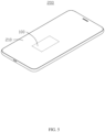
FIG. 5 , an embodiment of this application provides anelectronic apparatus 200, and theelectronic apparatus 200 includes a main body 220 and asecondary battery 100. Thesecondary battery 100 is accommodated in the main body 220. Theelectronic apparatus 200 may be one of a mobile phone, a tablet, or an e-reader. - In this application, taking the
electronic apparatus 200 being a mobile phone as an example, thesecondary battery 100 is disposed in the mobile phone to provide power for the mobile phone for use, and the main body 220 is of a structure of the mobile phone. It can be understood that in other embodiments, theelectronic apparatus 200 may alternatively be of other structures, and is not limited to the above mobile phone, tablet, or e-reader. - The following describes the performance of the battery provided in this application through specific examples and comparative examples.
- Insulating
adhesives 30 with a thickness h1 of 80 µm, and aluminum and nickel strips of 5×0.1 mm were subjected to hot-melt flat pressing to form a tab assembly as shown inFIG. 1 , where an overhang width of the insulatingadhesive 30 was 2.2 mm, and a distance between two insulatingadhesives 30 on the same side of thetab 20 was 20 mm. The overhang width of the insulatingadhesive 30 was a distance by which a side edge of the insulatingadhesive 30 extended beyond an edge of the tab on the same side along third direction Y (the width direction of the tab 20). - The above tab assembly was placed into a
packaging pouch 40 with a thickness T of 91 µm, and then heat-sealed using a heat-sealing head of 1.5 mm width, to obtain the secondary battery as shown inFIG. 1 , where a heat-sealing temperature was 205°C, a heat-sealing pressure was 0.4 MPa, and a heat-sealing time was 1.5S. - For the secondary battery, cutting was performed along the width direction or length direction of the
tab 20 to obtain samples, and cross-sections of the samples were tested using a "Keyence" VHX-5000 model microscope (with a magnification of 200X). Thicknesses of 5 to 10 points distributed uniformly in each of regions of the samples (a first insulatingadhesive layer 31, a second insulatingadhesive layer 32, a third insulatingadhesive layer 33, a first insulating adhesive bonding layer, a tab assembly, asealing layer 401, and a packaging pouch 40) were measured and recorded, and an average value was taken as the thickness of each layer. In the first direction, due to heat-sealing, boundaries between some components were blurred, and to assist in measuring the thickness of each component, an auxiliary line might be drawn based on the color difference between the components. The first insulating adhesive bonding layer was formed by bonding two first insulating adhesive layers together, and half of the thickness of the first insulating adhesive bonding layer could be considered as the thickness of the first insulating adhesive layer. - In a
first part 303, a thickness A1 of the first insulatingadhesive layer 31 was 14.8 µm, a thickness B1 of the second insulatingadhesive layer 32 was 15.6 µm, and a thickness C1 of the third insulatingadhesive layer 33 was 49.6 µm, where B1=19.5%h1, A1=94.87%B, and C1=317.95%B. A thickness t of thetab 20 was 100 µm. In asecond part 302, a thickness C2 of a second part of third insulatingadhesive layer 33 was 48.6 µm, a total thickness H of the second part of third insulatingadhesive layer 33 and thesealing layer 401 was 38.7 µm, a thickness A2 of a second part of first insulatingadhesive layer 31 was 14.9 µm, and a thickness B2 of a second part of second insulatingadhesive layer 32 was 14.8 µm. A thickness G of a part of the tab assembly corresponding to thesecond part 302 of the insulatingadhesive 30 was 260 µm, a thickness P of thesealing layer 401 was 35 µm, and a thickness K of a part of thesecondary battery 100 corresponding to thetab 20 and thesecond part 302 was 360 µm. In athird part 301, a thickness h3 of an insulatingadhesive 30 was 80 µm, a thickness A3 of a third part of first insulatingadhesive layer 31 was 14.8 µm, a thickness B3 of a third part of second insulatingadhesive layer 32 was 15.6 µm, and a thickness C3 of a third part of third insulatingadhesive layer 33 was 49.6 µm. In abonding region 201 of the tab assembly, a thickness Q of the tab assembly was 160 µm, a thickness D of a bonding region first insulating adhesive bonding layer was 29.6 µm, a thickness B4 of a bonding region second insulatingadhesive layer 32 was 15.6 µm, and a thickness C4 of a bonding region third insulatingadhesive layer 33 was 49.6 µm. - A material of the first insulating
adhesive layer 31 was PP, with a melting point of 145°C. The material of the second insulatingadhesive layer 32 was PP, with a melting point of 145°C. The third insulatingadhesive layer 33 included PP with a mass percentage of 95% and UHMWPE with a mass percentage of 5%, with a melting point of 120°C. - The resulting battery in Example 1 was subjected to a packaging tensile test, and whether the battery experienced electrolyte leakage was visually checked. The packaging tensile test was specifically as follows: Part of the battery corresponding to the tab and the second part of the insulating adhesive was cut in the width direction of the tab, to obtain a sample with a width of 5 mm and a length of 5 cm. The sample was clamped on a high-speed tensile machine, where the tab was fixed on an upper fixture and the packaging pouch was fixed on a lower fixture, with a stretching speed set to 175±5 mm/min. The sample was lifted upward in the 180-degree direction to be peeled off, and a peeling force was read. A value of the read peeling force (measured in N) was divided by a width of the sample, so as to calculate a sealing tensile force F (N/mm) of the sample.
- Examples 2-12 and Comparative examples 1-9 differ from Example 1 in the thickness A1 of the first insulating
adhesive layer 31, the thickness B1 of the second insulatingadhesive layer 32, and the thickness C1 of the third insulatingadhesive layer 33 in thefirst part 303 of the insulatingadhesive 30. The specific parameters and test results are shown in Table 1.
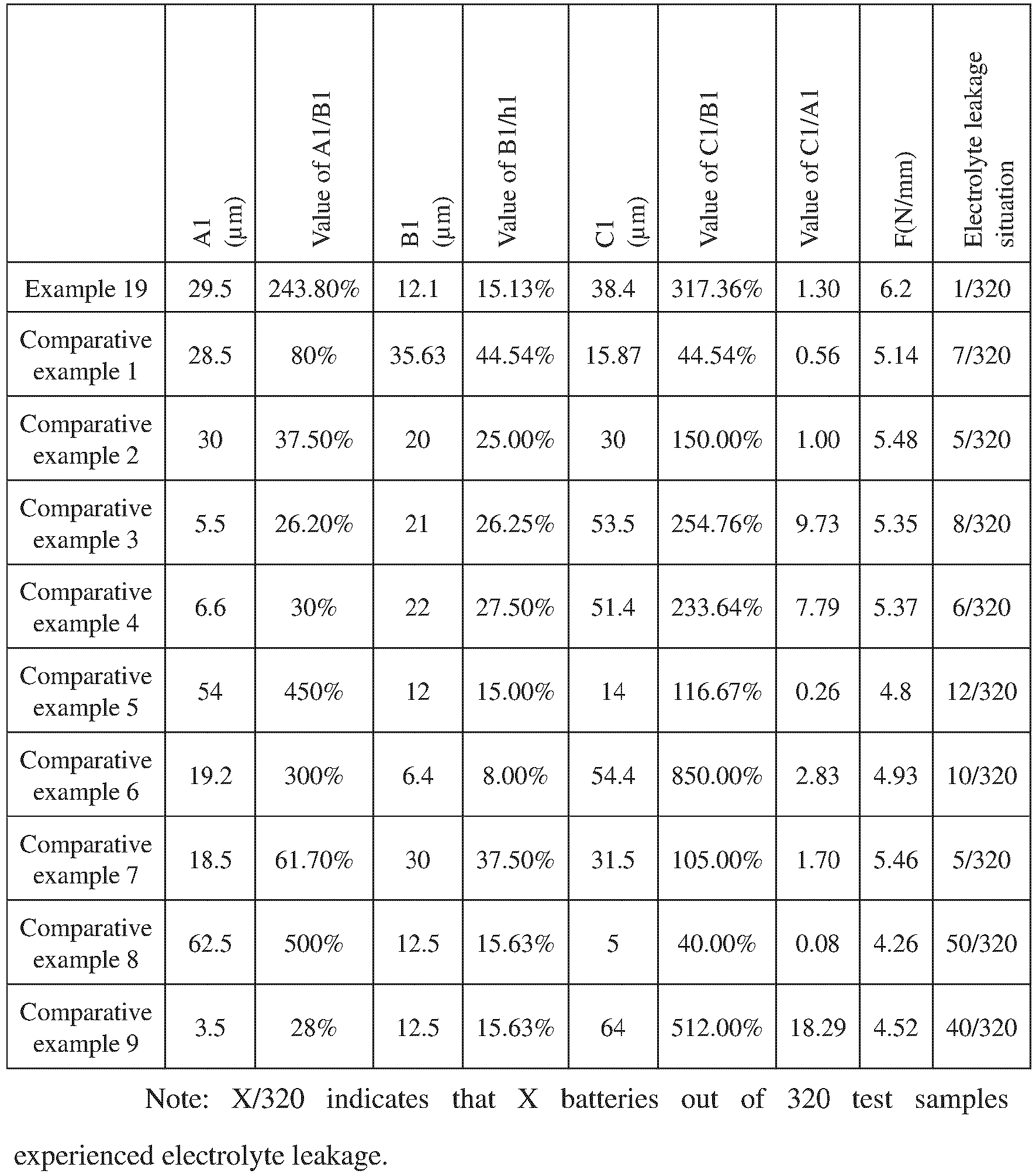
- Based on comparison between Examples 1-14 and Comparative examples 1-9, it can be known that when the insulating adhesive simultaneously satisfies 10.5%h1≤B1≤35%h1, 90%B1≤C1≤500%B1, C1>A1, 60%B1≤A1≤400%B1, the sealing tensile force F is greater than or equal to 5.5 N/mm, and the electrolyte leakage situation of the battery is reduced.
- Based on comparison between Examples 12 and 15-19, it can be known that 8.18A1≥C1≥1.05A1, within this range, the sealing tensile force is greater than or equal to 5.75 N, and when the thickness C1 of the third insulating
adhesive layer 33 is within the above range, thesecondary battery 100 can have high sealing strength, high insulation, and corrosion resistance. As the thickness of the third insulatingadhesive layer 33 increases, thesecondary battery 100 has increased sealing tensile force after sealing and is less prone to electrolyte leakage. However, if the thickness of the third insulatingadhesive layer 33 exceeds a certain range, insufficient melting and interface issues occur between the third insulatingadhesive layer 33, thesealing layer 401, and the second insulatingadhesive layer 32 during sealing, reducing the sealing tensile force and increasing the risk of electrolyte leakage in thesecondary battery 100. When the thickness C1 of the third insulatingadhesive layer 33 is within the above range, thesecondary battery 100 can have high sealing strength, high insulation, and corrosion resistance. Preferably, 7A1≥C1≥1.3A1. Within this range, the sealing tensile force is greater than or equal to 6.1N, such that the resultingsecondary battery 100 after sealing is less prone to electrolyte leakage. - Examples 20-23 and Comparative examples 10 and 11 differ from Example 1 in the thickness t of the
tab 20. Specific parameters and test results are shown in Table 2.Table 2 h1 (µm) t (µm) Value of 2h1/t F(N/mm) Electrolyte leakage situation Example 1 80 100 1.6 6.76 0/320 Example 20 80 145 0.9 6.35 0/320 Example 21 80 125 1.28 6.57 0/320 Example 22 80 53.3 3 5.5 4/320 Example 23 80 58 2.76 6.35 0/320 Comparative example 10 80 45 3.56 5.2 8/320 Comparative example 11 80 200 0.8 6.2 2/320 - From Table 2, it can be known that the sealing tensile force F increases with the increase in the value of 2h1/t. When 3≥2h1/t≥0.9, no batteries experience electrolyte leakage, completely avoiding the electrolyte leakage problem of the battery. When 2h1/t<0.9 or 2h1/t≥3, a thicker tab or insulating adhesive is less conducive to sealing, an electrolyte leakage channel is likely to be formed in the
third part 303 of the insulatingadhesive 30, and it is also likely to cause voids in the sealing portion during sealing of non-tab regions, leading to insufficient sealing and electrolyte leakage. - Examples 24 and 25 and Comparative examples 12-14 differ from Example 1 in at least one of the thickness C2 of the second part of third insulating
adhesive layer 33 in thesecond part 302 of the insulatingadhesive 30 or the thickness C1 of the second part of third insulatingadhesive layer 33 in thefirst part 301 of the insulatingadhesive 30. Specific parameters and test results are shown in Table 3.Table 3 C1 (µm) C2 (µm) Value of C2/C 1 C1-C2 F(N/mm) Electrolyte leakage situation Example 1 49.6 48.6 98% 1 6.76 0/320 Example 24 49.6 45.6 92% 3 6.71 0/320 Example 25 88 81 92% 7 6.69 0/320 Comparative example 12 49.6 39.6 79.8% 10. 5.47 5/320 Comparative example 13 49.6 49.1 99% 0.5 4.80 15/320 Comparative example 14 88 79.3 90% 8.7 4.80 15/320 - From Table 3, it can be known that when 92%C1≤C2≤98%C1 and 7 µm≥C1-C2≥1 µm are satisfied, no batteries experience electrolyte leakage, completely avoiding the electrolyte leakage problem of the battery and further improving the sealing effect. When C2>98%C1 or 1 µm>C1-C2, the third insulating
adhesive layer 33 cannot fuse with thesealing layer 401 due to an excessively low compression rate, reducing the sealing tensile force and causing electrolyte leakage. When C2<92%C1 or 7 µm<C1-C2, the insulatingadhesive 30 over-melts, and an excessively small thickness leads to reduced sealing effect and increased frequency of electrolyte leakage. - Examples 26-30 and Comparative examples 15 and 16 differ from Example 1 in at least one of the thickness A1 of the first insulating
adhesive layer 31, the thickness B1 of the second insulatingadhesive layer 32, and the thickness C1 of the third insulatingadhesive layer 33 in thefirst part 303 of the insulatingadhesive 30, the thickness C2 of the second part of third insulatingadhesive layer 33 in thesecond part 302 of the insulatingadhesive 30, or the total thickness H of the second part of third insulatingadhesive layer 33 in thesecond part 302 and thesealing layer 401. Specific parameters and test results are shown in Table 4.
- From Table 4, it can be known that when 0.25(C2+P)≤H≤0.75(C2+P) is satisfied, the sealing tensile force F is greater, and the number of batteries experiencing electrolyte leakage is reduced, alleviating the electrolyte leakage problem of the battery. When H/(C2+P)<0.25, the third insulating
adhesive layer 33 and thesealing layer 401 have poor interfacial fusion due to an excessively low compression rate, reducing the sealing tensile force and causing electrolyte leakage. When H/(C2+P)>0.75, the third insulatingadhesive layer 33 and thesealing layer 401 over-melt, and an excessively small thickness after heat melting leads to reduced sealing effect and increased frequency of electrolyte leakage. - Examples 31 and 32 and Comparative examples 17 and 18 differ from Example 1 in the thickness A2 of the second part of first insulating
adhesive layer 31 in thesecond part 302. Specific parameters and test results are shown in Table 5.Table 5 A1 (µm) A2 (µm) Al-A2 F(N/mm) Electrolyte leakage situation Example 1 14.8 12 2.8 6.76 0/320 Example 31 14.8 14.3 0.5 6.26 2/320 Example 32 14.8 9.8 5 6.65 0/320 Comparative example 17 14.8 14.6 0.2 4.85 12/320 Comparative example 18 14.8 5.5 10.2 5.15 9/320 - From Table 5, it can be known that when 5 µm≥A1-A2≥0.5 µm is satisfied, the sealing tensile force F is greater, and the number of batteries experiencing electrolyte leakage is reduced, alleviating the electrolyte leakage problem of the battery.
- Examples 33 and 34 and Comparative examples 19 and 20 differ from Example 1 in the thickness B2 of the second part of second insulating
adhesive layer 32 in thesecond part 302. Specific parameters and test results are shown in Table 6.Table 6 B1 (µm) B2 (µm) B1-B2 F(N/mm) Electrolyte leakage situation Example 1 15.6 14.8 0.8 6.76 0/320 Example 33 15.6 15.5 0.1 5.95 2/320 Example 34 15.6 12.7 2.9 6.63 0/320 Comparative example 19 15.6 8.4 7.2 5.32 8/320 Comparative example 20 15.6 6.4 9.2 4.93 10/320 - From Table 6, it can be known that when 3 µm≥B1-B2≥0.1 µm is satisfied, the sealing tensile force F is greater, and the number of batteries experiencing electrolyte leakage is reduced, alleviating the electrolyte leakage problem of the battery.
- Examples 35 and 36 and Comparative examples 21 and 22 differ from Example 1 in at least one of the thickness A1 of the first insulating
adhesive layer 31, the thickness B1 of the second insulatingadhesive layer 32, the thickness C1 of the third insulatingadhesive layer 33 in thefirst part 303 of the insulatingadhesive 30, the thickness G of the part of the tab assembly corresponding to thesecond part 302 of the insulatingadhesive 30, or the thickness K of the part of thesecondary battery 100 corresponding to thesecond part 302 and thetab 20. Specific parameters and test results are shown in Table 7.
- From Table 8, it can be known that when 2T+G-(2P+2t)×75%<K<2T+G-(2P+2t)×15% is satisfied, the sealing tensile force F is greater, and the number of batteries experiencing electrolyte leakage is reduced, alleviating the electrolyte leakage problem of the battery.
- Examples 37-49 and Comparative examples 23-31 differ from Example 1 in at least one of the thickness h3 of the
third part 301 of the insulatingadhesive 30, the thickness A3 of the third part of first insulatingadhesive layer 31, the thickness B3 of the third part of second insulatingadhesive layer 32, or the thickness C3 of the third part of third insulatingadhesive layer 33 in thethird part 301. Specific parameters and test results are shown in Table 8.Table 8 h3 A3 Value of A3/B3 B3 B3/h3 C3 C3/B3 C3/A3 F (N/mm) Electrolyte leakage situation Example 1 80 14.8 94.87% 15.6 19.50% 49.6 317.95% 3.35 6.76 0/320 Example 37 79.3 14.6 74.87% 19.5 24.59% 45.2 231.79% 3.1 6.3 1/320 Example 38 79.7 15 60.73% 24.7 30.99% 40 161.94% 2.7 5.9 2/320 Example 39 78 19 95.00% 20 25.64% 39 195.00% 2.1 6.5 0/320 Example 40 80 24 240.00% 10. 12.50% 46 460.00% 1.9 6.51 0/320 Example 41 80 32 290.91% 11 13.75% 37 336.36% 1.2 6.2 0/320 Example 42 80 10.8 60.00% 18 22.50% 51.2 284.44% 4.7 6.65 0/320 Example 43 80 33.6 400.00% 8.4 10.50% 38 452.38% 1.1 5.7 3/320 Example 44 80 32.9 391.67% 8.4 10.50% 38.7 460.71% 1.2 5.8 1/320 Example 45 80 18.3 65.36% 28 35.00% 33.7 120.36% 1.8 6.25 1/320 Example 46 79.7 25.20 90.00% 28 35.13% 26.5 94.64% 1.1 5.5 4/320 Example 47 80 8 66.67% 12 15.50% 60 500% 8.3 5.75 4/320 Example 48 80 29.9 249.17% 12 15.00% 38.1 317.50% 1.3 6.3 1/320 Example 49 80 29.6 328.89% 9 11.25% 41.4 460.00% 1.4 6.33 0/320 Comparative example 23 80 28 76.44% 36.63 45.79% 15.37 41.96% 0.5 5.1 7/320 Comparative example 24 80 29 145.00% 20 25.00% 31 155.00% 1.1 5.45 5/320 Comparative example 25 80 6.5 32.50% 20 25.00% 53.5 267.50% 8.2 5.37 7/320 Comparative example 26 80 7.6 34.55% 22 27.50% 50.4 229.09% 6.6 5.3 6/320 Comparative example 27 80 54 450.00% 12 15.00% 14 116.67% 0.3 4.7 11/320 Comparative example 28 80 18.6 290.63% 6.4 8.00% 55 859.38% 3.0 4.8 10/320 Comparative example 29 80 19.5 67.24% 29 36.25% 31.5 108.62% 1.6 5.3 5/320 Comparative example 30 80 62.5 543.48% 11.5 14.38% 6 52.17% 0.1 4.3 45/320 Comparative example 31 80 2.5 20.00% 12.5 15.63% 65 520.00% 26.0 4.5 40/320 - Based on comparison between Examples 30-43 and Comparative examples 22-30, it can be known that when the insulating
adhesive 30 simultaneously satisfies 10.5%h3≤B3≤35%h3, 90%B3≤C3≤500%B3, C3>A3, and 60%B3≤A3≤400%B3, the sealing tensile force F is greater than or equal to 5.5 N/mm, and the electrolyte leakage situation of the battery is reduced. - Examples 50-62 and Comparative examples 32-40 differ from Example 1 in at least one of the thickness Q of the
bonding region 201 of the tab assembly, the thickness D of the bonding region first insulating adhesive bonding layer, the thickness B4 of the bonding region second insulatingadhesive layer 32, or the thickness C4 of the bonding region third insulatingadhesive layer 33. Specific parameters and test results are shown in Table 9.Table 9 Q D D/B4 B4 B4/0.5Q C4 C4/B4 C4/0.5D F(N/mm) Electrolyte leakage situation Example 1 160 29.6 189.74% 15.6 19.50% 49.6 317.95% 3.4 6.76 0/320 Example 50 159.4 30 152.28% 19.7 24.72% 45 228.43% 3 6.35 1/320 Example 51 160.4 30 121.46% 24.7 30.80% 40.5 163.97% 2.7 5.85 2/320 Example 52 160 44 209.52% 21 26.25% 37 176.19% 1.7 6.4 0/320 Example 53 160 50 500.00% 10. 12.50% 45 450.00% 1.8 6.41 0/320 Example 54 160 60 428.57% 14 17.50% 36 257.14% 1.2 6.3 0/320 Example 55 160 21.6 120.00% 18 22.50% 51.2 284.44% 4.7 6.55 0/320 Example 56 160 67.2 800.00% 8.4 10.50% 38 452.38% 1.1 5.75 3/320 Example 57 160 64 711.11% 9 11.25% 39 433.33% 1.2 5.88 1/320 Example 58 170 36 128.57% 28 32.94% 39 139.29% 2.2 6.2 1/320 Example 59 160 50.4 175.00% 28.8 36.00% 26 90.28% 1 5.5 4/320 Example 60 160 16 133.33% 12 15.00% 60 500.00% 7.5 5.5 4/320 Example 61 160 59.4 495.00% 12 15.00% 38.3 319.17% 1.3 6.2 1/320 Example 62 160 59 655.56% 9 11.25% 41.5 461.11 % 1.4 6.23 0/320 Comparative example 32 160 58 160.22% 36.2 45.25% 14.8 40.88% 0.5 5.1 7/320 Comparative example 33 160 58 276.19% 21 26.25% 30 142.86% 1 5.45 5/320 Comparative example 34 160 13 59.09% 22 27.50% 51.5 234.09% 7.9 5.4 7/320 Comparative example 35 160 15.2 69.09% 22 27.50% 50.4 229.09% 6.6 5.3 8/320 Comparative example 36 160 106 815.38% 13 16.25% 14 107.69% 0.3 4.6 11/320 Comparative example 37 160 35.2 475.68% 7.4 9.25% 55 743.24% 3.1 4.8 10/320 Comparative example 38 160 39 134.48% 29 36.25% 31.5 108.62% 1.6 5.2 5/320 Comparative example 39 160 127 1209.52% 10.5 13.13% 6 57.14% 0.1 4.3 45/320 Comparative example 40 160 5 40.00% 12.5 15.63% 65 520.00% 26 4.4 40/320 - From Table 9, it can be known that when 10.5%(Q×0.5)≤B4≤35%(Q×0.5), C4>0.5D, 90%B4≤C4≤500%B4, and 120%B4≤D≤800%B4 are satisfied simultaneously, the sealing tensile force F is greater than or equal to 5.5 N/mm, and the electrolyte leakage situation of the battery is reduced.
- Examples 63-68 and Comparative examples 41 and 42 differ from Example 1 in materials of the first insulating
adhesive layer 31, the second insulatingadhesive layer 32, and the third insulatingadhesive layer 33. Specific parameters and test results are shown in Table 10.Table 10 Example 1 Example 63 Example 64 Example 65 Example 66 Example 67 Example 68 Comparative example 41 Comparative example 42 First insulating adhesive layer PP 100% 100% 100% 100% 100% 100% 95% 100% 100% ERP 5% 12% UHMWPE 2% Melting point (°C) 123 123 123 123 123 123 110 105 98 Second insulating adhesive layer PP 100% 100% 100% 100% 100% 100% 100% 100% 100% Melting point (°C) 145 145 145 145 145 145 145 145 145 Third insulating adhesive layer PP 95% 97% 90% 97% 90% 100% 100% 98% ERP 3% 10% 12% UHMWPE 5% 3% 10% 2% Melting point (°C) 120 121 119 121 115 123 123 122 98 F(N/mm) 6.76 6.40 6.30 6.53 6.22 6.20 6.20 5.35 3.10 Electrolyte leakage situation 0/320 1/320 1/320 0/320 1/320 0/320 0/320 6/320 50/320 - From Table 10, it can be known that when a percentage of the toughening modifier added in the third
adhesive layer 33 is 3%-10%, the sealing tensile force F reaches 6.22 N/mm, and the number of batteries experiencing electrolyte leakage is reduced, alleviating the electrolyte leakage problem of the battery. When the percentage of the toughening modifier added in the first insulatingadhesive layer 31 is 3%-10%, the number of batteries experiencing electrolyte leakage is reduced, alleviating the electrolyte leakage problem of the battery. When the percentage of the toughening modifier added is not within the range of 3%-10%, the number of batteries experiencing electrolyte leakage increases, increasing the possibility of electrolyte leakage of the battery. - The descriptions disclosed above are merely preferred embodiments of this application, and certainly cannot constitute any limitation on this application. Accordingly, equivalent changes made in accordance with this application still fall within the scope of this application.
Claims (21)
- A secondary battery, comprising an electrode assembly, a tab assembly, and a packaging pouch, wherein the electrode assembly is accommodated in the packaging pouch, the packaging pouch comprises a sealing portion, the tab assembly comprises tab and insulating adhesives respectively disposed on two sides of each tab, the tab are connected to the electrode assembly and run through the sealing portion to extend out of the packaging pouch, and the insulating adhesive connect the tab and the packaging pouch, wherein the insulating adhesive comprises a first insulating adhesive layer, a second insulating adhesive layer, and a third insulating adhesive layer sequentially stacked in a first direction, wherein the first insulating adhesive layer is connected to the tab, and the third insulating adhesive layer is connected to the packaging pouch; and in a second direction perpendicular to the first direction, the insulating adhesive comprises a first part, wherein the first part is a region at which the insulating adhesive overlaps the tab in the first direction and is not overlap the sealing portion, the first part comprises a first end portion, and the first end portion is located in the packaging pouch, wherein in the first end portion, in the first direction, a thickness of the insulating adhesive is h1, a thickness of the first insulating adhesive layer is A1, a thickness of the second insulating adhesive layer is B1, and a thickness of the third insulating adhesive layer is C1, wherein 10.5%h1≤B1≤35%h1, C1>A1, 90%B1≤C1≤500%B1, and 60%B1≤A1≤400%B1.
- The secondary battery according to claim 1, wherein 8.18A1≥C1≥1.05A1.
- The secondary battery according to claim 1, wherein 7A1≥C1≥1.3A1.
- The secondary battery according to claim 1, wherein a thickness of the tab in the first direction is t, wherein 3t≥2h1≥0.9t.
- The secondary battery according to claim 1, wherein in the second direction, the insulating adhesive further comprises a second part; the second part is a region at which the insulating adhesive overlaps the sealing portion in the first direction; in the second part, the insulating adhesive comprises a second part of first insulating adhesive layer, a second part of second insulating adhesive layer, and a second part of third insulating adhesive layer sequentially stacked in the first direction; and in the first direction, thicknesses of the second part of first insulating adhesive layer, the second part of second insulating adhesive layer, and the second part of third insulating adhesive layer are A2, B2, and C2, respectively.
- The secondary battery according to claim 5, wherein 92%C1≤C2≤98%C1.
- The secondary battery according to claim 5, wherein 7 µm≥C1-C2≥1 µm.
- The secondary battery according to claim 5, wherein the packaging pouch comprises a sealing layer connected to the third insulating adhesive layer, and a thickness of the sealing layer in the first direction is P; and in the second part, a total thickness of the second part of third insulating adhesive layer and the sealing layer in the first direction is H, wherein 0.25(C2+P)≤H≤0.75(C2+P).
- The secondary battery according to claim 8, wherein 0.4(C2+P)≤H≤0.7(C2+P).
- The secondary battery according to claim 5, wherein A1 and A2 satisfy the following formula: 5 µm≥A1-A2≥0.5 µm.
- The secondary battery according to claim 5, wherein 3 µm≥B1-B2≥0.1 µm.
- The secondary battery according to claim 5, wherein the packaging pouch comprises a sealing layer connected to the third insulating adhesive layer, and in the first direction, a thickness of the packaging pouch is T and a thickness of the sealing layer is P; and in the first direction, a thickness of a part of the tab assembly corresponding to the second part is G and a thickness of a part of the secondary battery corresponding to the second part and the tab is K, wherein 2T+G-(2P+2t)×75%<K<2T+G-(2P+2t)×15%.
- The secondary battery according to claim 1, wherein in the second direction, the insulating adhesive further comprises a third part; the third part is a region at which the insulating adhesive does not overlap the sealing portion or the tab in the first direction; in the third part, in the first direction, the insulating adhesive comprises a third part of first insulating adhesive layer, a third part of second insulating adhesive layer, and a third part of third insulating adhesive layer sequentially stacked in the first direction; and a thickness of the insulating adhesive is h3, a thickness of the first insulating adhesive layer is A3, a thickness of the second insulating adhesive layer is B3, and a thickness of the third insulating adhesive layer is C3, wherein 10.5%h3≤B3≤35%h3, C3>A3, 90%B3≤C3≤500%B3, and 60%B3≤A3≤400%B3.
- The secondary battery according to claim 1, wherein the tab assembly comprises a bonding region, and the bonding region is a part at which the insulating adhesives on two sides of the tab adhere to each other in the first direction; and in the first direction, the bonding region comprises a first insulating adhesive bonding layer, a bonding region second insulating adhesive layer, and a bonding region third insulating adhesive layer, a thickness of the bonding region is Q, a thickness of the first insulating adhesive bonding layer is D, a thickness of the bonding region second insulating adhesive layer is B4, and a thickness of the bonding region third insulating adhesive layer is C4, wherein 10.5%(Q×0.5)≤B4≤35%(Q×0.5), C4>0.5D, 90%B4≤C4≤500%B4, and 120%B4≤D≤800%B4.
- The secondary battery according to claim 1, wherein melting points of the first insulating adhesive layer and the third insulating adhesive layer are 100-140°C, and a melting point of the second insulating adhesive layer is 140-200°C.
- The secondary battery according to claim 1, wherein the first insulating adhesive layer, the second insulating adhesive layer, and the third insulating adhesive layer each comprise one or more of polypropylene, polyethylene, poly(vinylidene difluoride), vinylidene fluoride-hexafluoropropylene copolymer, polymethyl methacrylate, or polyethylene glycol.
- The secondary battery according to claim 16, wherein the first insulating adhesive layer and/or the third insulating adhesive layer further comprises a toughening modifier.
- The secondary battery according to claim 17, wherein the toughening modifier comprises one or more of ethylene propylene rubber, ethylene propylene diene monomer rubber, styrene-butadiene rubber, low-density polyethylene, ethylene-vinyl acetate copolymer, linear low-density polyethylene, nylon, polyethylene terephthalate, polycarbonate, or ultra-high-molecular-weight polyethylene.
- The secondary battery according to claim 17, wherein based on a total mass of the first insulating adhesive layer, a percentage of the toughening modifier is 3%-10%; and/or based on a total mass of the third insulating adhesive layer, a percentage of the toughening modifier is 3%-10%.
- The secondary battery according to claim 1, wherein h1 is 30-160 µm.
- An electronic apparatus, comprising the secondary battery according to any one of claims 1 to 20.
Applications Claiming Priority (1)
| Application Number | Priority Date | Filing Date | Title |
|---|---|---|---|
| PCT/CN2022/120612 WO2024060145A1 (en) | 2022-09-22 | 2022-09-22 | Secondary battery and electronic apparatus comprising same |
Publications (2)
| Publication Number | Publication Date |
|---|---|
| EP4583267A1 true EP4583267A1 (en) | 2025-07-09 |
| EP4583267A4 EP4583267A4 (en) | 2025-12-03 |
Family
ID=88719877
Family Applications (1)
| Application Number | Title | Priority Date | Filing Date |
|---|---|---|---|
| EP22959153.2A Pending EP4583267A4 (en) | 2022-09-22 | 2022-09-22 | SECONDARY BATTERY AND ELECTRONIC DEVICE WITH IT |
Country Status (4)
| Country | Link |
|---|---|
| US (1) | US20250219260A1 (en) |
| EP (1) | EP4583267A4 (en) |
| CN (1) | CN117083755A (en) |
| WO (1) | WO2024060145A1 (en) |
Families Citing this family (3)
| Publication number | Priority date | Publication date | Assignee | Title |
|---|---|---|---|---|
| CN117855760A (en) * | 2024-01-08 | 2024-04-09 | 宁德新能源科技有限公司 | Insulation glue, tab assembly and secondary battery |
| CN117855767A (en) * | 2024-01-09 | 2024-04-09 | 宁德新能源科技有限公司 | Insulation parts, tab components, battery cells, batteries and electrical equipment |
| CN117855768A (en) * | 2024-01-09 | 2024-04-09 | 宁德新能源科技有限公司 | Insulation parts, tab components, battery cells, batteries and electrical equipment |
Family Cites Families (12)
| Publication number | Priority date | Publication date | Assignee | Title |
|---|---|---|---|---|
| JP4635415B2 (en) * | 2003-07-15 | 2011-02-23 | 凸版印刷株式会社 | Sealing material for electrode tab |
| JP2014229505A (en) * | 2013-05-23 | 2014-12-08 | 日立マクセル株式会社 | Thin battery encapsulant |
| CN203528010U (en) * | 2013-10-14 | 2014-04-09 | 东莞新能源科技有限公司 | Electrode lug glue for soft-packing lithium ion battery and electrode lug |
| KR101851485B1 (en) * | 2014-03-19 | 2018-04-23 | 도판 인사츠 가부시키가이샤 | Secondary battery |
| US10543667B2 (en) * | 2016-12-30 | 2020-01-28 | Toray Plastics (America), Inc. | Easy opening metalized hermetic films and methods to manufacture the same |
| CN106784998B (en) * | 2017-01-22 | 2024-10-15 | 宁德新能源科技有限公司 | Secondary battery and heating device |
| JP7136102B2 (en) * | 2017-07-24 | 2022-09-13 | 大日本印刷株式会社 | Adhesive film for metal terminal, metal terminal with adhesive film for metal terminal, battery using said adhesive film for metal terminal, and method for manufacturing battery |
| EP4738588A2 (en) * | 2020-03-30 | 2026-05-06 | Ningde Amperex Technology Limited | Cell and electronic device having same |
| JP7508915B2 (en) | 2020-07-16 | 2024-07-02 | 大日本印刷株式会社 | Adhesive film for metal terminal, metal terminal with adhesive film for metal terminal, metal terminal with adhesive film, method for manufacturing metal terminal with adhesive film using said adhesive film for metal terminal, electricity storage device using said adhesive film for metal terminal, and method for manufacturing electricity storage device |
| JP2022084420A (en) * | 2020-11-26 | 2022-06-07 | 双葉電子工業株式会社 | Tab lead and non-aqueous electrolyte device |
| CN113097617A (en) * | 2021-03-30 | 2021-07-09 | 宁德新能源科技有限公司 | Electrochemical device and electronic device |
| CN113097434B (en) * | 2021-03-30 | 2022-05-24 | 宁德新能源科技有限公司 | Electrochemical device and electronic device |
-
2022
- 2022-09-22 WO PCT/CN2022/120612 patent/WO2024060145A1/en not_active Ceased
- 2022-09-22 CN CN202280017424.1A patent/CN117083755A/en active Pending
- 2022-09-22 EP EP22959153.2A patent/EP4583267A4/en active Pending
-
2025
- 2025-03-21 US US19/086,450 patent/US20250219260A1/en active Pending
Also Published As
| Publication number | Publication date |
|---|---|
| CN117083755A (en) | 2023-11-17 |
| WO2024060145A1 (en) | 2024-03-28 |
| US20250219260A1 (en) | 2025-07-03 |
| EP4583267A4 (en) | 2025-12-03 |
Similar Documents
| Publication | Publication Date | Title |
|---|---|---|
| EP4583267A1 (en) | Secondary battery and electronic apparatus comprising same | |
| JP5422842B2 (en) | Electrochemical devices | |
| US10109826B2 (en) | Secondary battery | |
| JP4491843B2 (en) | Lithium ion secondary battery and method of sealing a lithium ion secondary battery container | |
| KR101280798B1 (en) | Electrochemical device and process of manufacturing same | |
| KR102507154B1 (en) | Terminal coating resin film for secondary cell, tab member for secondary cell, and secondary cell | |
| EP2600435B1 (en) | Electrical component, nonaqueous-electrolyte cell, and lead wire and sealable container both for use therein | |
| JP2014026980A (en) | Electrochemical device | |
| CN111509152A (en) | Metal terminal-coated resin film for secondary battery and battery pack | |
| CN115995636B (en) | Secondary battery and electronic device comprising same | |
| JP2022068237A (en) | Sealing film, and tab lead and secondary battery using the same | |
| WO2015115371A1 (en) | Terminal film for electricity storage devices, and electricity storage device | |
| WO2023017683A1 (en) | Outer package material for all-solid-state batteries, and all-solid-state battery | |
| JP2020050439A (en) | Power storage device | |
| JP2024133377A (en) | Resin film for terminals and power storage device using same | |
| JP7206745B2 (en) | Package with valve device and power storage device | |
| CN111312937A (en) | Aluminum-plastic film, manufacturing method thereof and battery using aluminum-plastic film | |
| JP2025104355A (en) | Resin film for terminals | |
| CN119404355A (en) | Terminal film for power storage device and power storage device using the same | |
| JP7187927B2 (en) | storage device | |
| JP2023014551A (en) | Tab lead, method of manufacturing the same, and laminate type battery or capacitor including the tab lead | |
| KR102914707B1 (en) | Pouch film, pouch case comprising the same and secondary battery | |
| KR20260006996A (en) | Pouch film lamination, pouch-type battery case and pouch-type secondary battery | |
| KR20260045684A (en) | Pouch film lamination, pouch-type battery case and pouch-type secondary battery | |
| KR20250038186A (en) | Pouch film lamination, pouch-type battery case and pouch-type secondary battery |
Legal Events
| Date | Code | Title | Description |
|---|---|---|---|
| STAA | Information on the status of an ep patent application or granted ep patent |
Free format text: STATUS: THE INTERNATIONAL PUBLICATION HAS BEEN MADE |
|
| PUAI | Public reference made under article 153(3) epc to a published international application that has entered the european phase |
Free format text: ORIGINAL CODE: 0009012 |
|
| STAA | Information on the status of an ep patent application or granted ep patent |
Free format text: STATUS: REQUEST FOR EXAMINATION WAS MADE |
|
| 17P | Request for examination filed |
Effective date: 20250331 |
|
| AK | Designated contracting states |
Kind code of ref document: A1 Designated state(s): AL AT BE BG CH CY CZ DE DK EE ES FI FR GB GR HR HU IE IS IT LI LT LU LV MC MK MT NL NO PL PT RO RS SE SI SK SM TR |
|
| A4 | Supplementary search report drawn up and despatched |
Effective date: 20251105 |
|
| RIC1 | Information provided on ipc code assigned before grant |
Ipc: H01M 50/186 20210101AFI20251030BHEP Ipc: H01M 50/105 20210101ALI20251030BHEP Ipc: H01M 50/197 20210101ALI20251030BHEP Ipc: H01M 50/121 20210101ALI20251030BHEP Ipc: H01M 50/126 20210101ALI20251030BHEP Ipc: H01M 50/184 20210101ALI20251030BHEP Ipc: H01M 50/193 20210101ALI20251030BHEP Ipc: H01M 50/198 20210101ALI20251030BHEP Ipc: H01M 50/178 20210101ALI20251030BHEP Ipc: H01M 50/557 20210101ALI20251030BHEP Ipc: H01M 50/55 20210101ALN20251030BHEP Ipc: H01M 50/119 20210101ALN20251030BHEP |
|
| DAV | Request for validation of the european patent (deleted) | ||
| DAX | Request for extension of the european patent (deleted) | ||
| TPAC | Observations filed by third parties |
Free format text: ORIGINAL CODE: EPIDOSNTIPA |
|
| TPAC | Observations filed by third parties |
Free format text: ORIGINAL CODE: EPIDOSNTIPA |