EP4583266A1 - Energy-storage device and electricity-consumption apparatus - Google Patents
Energy-storage device and electricity-consumption apparatus Download PDFInfo
- Publication number
- EP4583266A1 EP4583266A1 EP24221818.8A EP24221818A EP4583266A1 EP 4583266 A1 EP4583266 A1 EP 4583266A1 EP 24221818 A EP24221818 A EP 24221818A EP 4583266 A1 EP4583266 A1 EP 4583266A1
- Authority
- EP
- European Patent Office
- Prior art keywords
- tab
- electrode assembly
- energy
- connector
- storage device
- Prior art date
- Legal status (The legal status is an assumption and is not a legal conclusion. Google has not performed a legal analysis and makes no representation as to the accuracy of the status listed.)
- Pending
Links
Images



Classifications
-
- H—ELECTRICITY
- H01—ELECTRIC ELEMENTS
- H01M—PROCESSES OR MEANS, e.g. BATTERIES, FOR THE DIRECT CONVERSION OF CHEMICAL ENERGY INTO ELECTRICAL ENERGY
- H01M50/00—Constructional details or processes of manufacture of the non-active parts of electrochemical cells other than fuel cells, e.g. hybrid cells
- H01M50/10—Primary casings; Jackets or wrappings
- H01M50/172—Arrangements of electric connectors penetrating the casing
-
- H—ELECTRICITY
- H01—ELECTRIC ELEMENTS
- H01M—PROCESSES OR MEANS, e.g. BATTERIES, FOR THE DIRECT CONVERSION OF CHEMICAL ENERGY INTO ELECTRICAL ENERGY
- H01M50/00—Constructional details or processes of manufacture of the non-active parts of electrochemical cells other than fuel cells, e.g. hybrid cells
- H01M50/50—Current conducting connections for cells or batteries
- H01M50/531—Electrode connections inside a battery casing
- H01M50/533—Electrode connections inside a battery casing characterised by the shape of the leads or tabs
-
- H—ELECTRICITY
- H01—ELECTRIC ELEMENTS
- H01M—PROCESSES OR MEANS, e.g. BATTERIES, FOR THE DIRECT CONVERSION OF CHEMICAL ENERGY INTO ELECTRICAL ENERGY
- H01M50/00—Constructional details or processes of manufacture of the non-active parts of electrochemical cells other than fuel cells, e.g. hybrid cells
- H01M50/10—Primary casings; Jackets or wrappings
- H01M50/172—Arrangements of electric connectors penetrating the casing
- H01M50/174—Arrangements of electric connectors penetrating the casing adapted for the shape of the cells
- H01M50/178—Arrangements of electric connectors penetrating the casing adapted for the shape of the cells for pouch or flexible bag cells
-
- H—ELECTRICITY
- H01—ELECTRIC ELEMENTS
- H01M—PROCESSES OR MEANS, e.g. BATTERIES, FOR THE DIRECT CONVERSION OF CHEMICAL ENERGY INTO ELECTRICAL ENERGY
- H01M50/00—Constructional details or processes of manufacture of the non-active parts of electrochemical cells other than fuel cells, e.g. hybrid cells
- H01M50/40—Separators; Membranes; Diaphragms; Spacing elements inside cells
- H01M50/471—Spacing elements inside cells other than separators, membranes or diaphragms; Manufacturing processes thereof
- H01M50/474—Spacing elements inside cells other than separators, membranes or diaphragms; Manufacturing processes thereof characterised by their position inside the cells
-
- H—ELECTRICITY
- H01—ELECTRIC ELEMENTS
- H01M—PROCESSES OR MEANS, e.g. BATTERIES, FOR THE DIRECT CONVERSION OF CHEMICAL ENERGY INTO ELECTRICAL ENERGY
- H01M50/00—Constructional details or processes of manufacture of the non-active parts of electrochemical cells other than fuel cells, e.g. hybrid cells
- H01M50/40—Separators; Membranes; Diaphragms; Spacing elements inside cells
- H01M50/471—Spacing elements inside cells other than separators, membranes or diaphragms; Manufacturing processes thereof
- H01M50/477—Spacing elements inside cells other than separators, membranes or diaphragms; Manufacturing processes thereof characterised by their shape
-
- H—ELECTRICITY
- H01—ELECTRIC ELEMENTS
- H01M—PROCESSES OR MEANS, e.g. BATTERIES, FOR THE DIRECT CONVERSION OF CHEMICAL ENERGY INTO ELECTRICAL ENERGY
- H01M50/00—Constructional details or processes of manufacture of the non-active parts of electrochemical cells other than fuel cells, e.g. hybrid cells
- H01M50/40—Separators; Membranes; Diaphragms; Spacing elements inside cells
- H01M50/471—Spacing elements inside cells other than separators, membranes or diaphragms; Manufacturing processes thereof
- H01M50/48—Spacing elements inside cells other than separators, membranes or diaphragms; Manufacturing processes thereof characterised by the material
- H01M50/486—Organic material
-
- H—ELECTRICITY
- H01—ELECTRIC ELEMENTS
- H01M—PROCESSES OR MEANS, e.g. BATTERIES, FOR THE DIRECT CONVERSION OF CHEMICAL ENERGY INTO ELECTRICAL ENERGY
- H01M50/00—Constructional details or processes of manufacture of the non-active parts of electrochemical cells other than fuel cells, e.g. hybrid cells
- H01M50/50—Current conducting connections for cells or batteries
- H01M50/543—Terminals
- H01M50/547—Terminals characterised by the disposition of the terminals on the cells
- H01M50/55—Terminals characterised by the disposition of the terminals on the cells on the same side of the cell
-
- Y—GENERAL TAGGING OF NEW TECHNOLOGICAL DEVELOPMENTS; GENERAL TAGGING OF CROSS-SECTIONAL TECHNOLOGIES SPANNING OVER SEVERAL SECTIONS OF THE IPC; TECHNICAL SUBJECTS COVERED BY FORMER USPC CROSS-REFERENCE ART COLLECTIONS [XRACs] AND DIGESTS
- Y02—TECHNOLOGIES OR APPLICATIONS FOR MITIGATION OR ADAPTATION AGAINST CLIMATE CHANGE
- Y02E—REDUCTION OF GREENHOUSE GAS [GHG] EMISSIONS, RELATED TO ENERGY GENERATION, TRANSMISSION OR DISTRIBUTION
- Y02E60/00—Enabling technologies; Technologies with a potential or indirect contribution to GHG emissions mitigation
- Y02E60/10—Energy storage using batteries
Definitions
- the disclosure relates to the field of energy-storage, and in particular, to an energy-storage device and an electricity-consumption apparatus.
- Secondary batteries also known as rechargeable batteries or storage batteries, refer to batteries that can continue to be used by reactivating the active material through charging after the batteries are discharged.
- the recyclable nature of the secondary battery has gradually made them the main power source for electricity-consumption apparatuses. As the demand for the secondary battery increases, there are higher requirements for their energy density, reliability, and cost.
- the size of the electrode assembly is typically made larger.
- a larger electrode assembly further reduces the gap between the electrode assembly and the top cover.
- the space for arranging the tab becomes very limited, and the tab is prone to stress concentration, which leads to a decline in the stability of the electrical connection, thereby reducing the reliability of the secondary battery.
- a purpose of the disclosure is to provide an energy-storage device and an electricity-consumption apparatus to address the issue of stress concentration occurring in a tab, which may lead to a decrease in the stability of the electrical connection and a reduction in the reliability of a secondary battery.
- an energy-storage device in a first aspect, includes an electrode assembly, a tab, a connector, and a lower plastic assembly.
- One end of the tab is connected to the electrode assembly, and the tab extends in a bent manner.
- the connector is connected to another end of the tab.
- the lower plastic assembly has a first surface and a second surface opposite the first surface. The first surface faces towards the tab.
- the connector is located between the lower plastic assembly and the electrode assembly.
- An avoidance recess is defined in the first surface. The avoidance recess is located at an edge of the lower plastic assembly in a width direction of the lower plastic assembly and extends in a length direction of the lower plastic assembly.
- the tab has an extension portion, a bent portion, an inclined portion, and a connection portion that are sequentially connected.
- One end of the extension portion away from the bent portion is connected to the electrode assembly.
- One end of the connection portion away from the inclined portion is connected to the connector, and the bent portion extends in a bent manner and extends into the avoidance recess.
- the avoidance recess is defined in the first surface of the lower plastic assembly to accommodate at least part of the tab, increasing the space available for arranging the tab. This ample arrangement space for the tab reduces stress concentration, thereby preventing a decrease in the stability of the electrical connection and ensuring the reliability of the energy-storage device. Since the avoidance recess can accommodate at least part of the tab, more space is available for bending of the tab. This reduces the bending angle of the tab, thereby decreasing stress concentration. By configuring the bent portion to extend into the avoidance recess, the bending angle of the bent portion can be increased, thereby enlarging the included angle between the inclined portion and the extension portion. This prevents the bending angle of the bent portion from being too small, as a too small bending angle would otherwise reduce the included angle between the inclined portion and the extension portion and lead to stress concentration.
- the connector is spaced apart from the extension portion. This creates a gap between the extension portion and the connector, allowing for the arrangement of the inclined portion. This configuration allows the gap between the extension portion and the connector to be utilized for the arrangement of the tab, thereby expanding the space for the arrangement of the tab and further reducing stress concentration.
- one end of the inclined portion connected to the bent portion is spaced apart from the electrode assembly by a first distance
- another end of the inclined portion connected to the connection portion is spaced apart from the electrode assembly by a second distance
- the first distance is greater than the second distance. Setting the first distance greater than the second distance allows the one end of the inclined portion connected to the bent portion to be farther away from the electrode assembly than the another end of the inclined portion connected to the connection portion. That is, with respect to the electrode assembly as a reference, the height of the one end of the inclined portion connected to the bent portion is higher, while the height of the another end of the inclined portion connected to the connection portion is lower. This arrangement allows the bent portion to extend into the avoidance recess, while the connection portion can be easily connected to the connector.
- the connector has a third surface and a fourth surface opposite the third surface, where the third surface is opposite to the first surface, and the connection portion is connected to the fourth surface.
- the connection portion is connected to the fourth surface, making the connection process between the tab and the connector easier.
- the connector has an inclined surface, where the inclined surface connects the third surface to the fourth surface, and the inclined surface faces towards the inclined portion.
- the inclined portion and the connection portion define a first included angle A
- the inclined surface and the fourth surface define a second included angle B
- the first included angle A and the second included angle B satisfy 0° ⁇
- the first included angle A and the second included angle B satisfy 0° ⁇
- the tab protrudes beyond the third surface.
- Such an arrangement allows a space of the avoidance recess to accommodate at least part of the tab, thereby increasing the space for the arrangement of the tab and reducing stress concentration.
- a side wall of the avoidance recess closer to a center of the lower plastic assembly is aligned with a side edge of the connector. In this way, the connector in third direction does not significantly occupy the space of the avoidance recess, allowing sufficient room for the arrangement of the tab.
- the explosion-proof valve 55 is arranged on the top cover 51.
- the explosion-proof valve 55 will rupture to release the gas, thereby preventing accidents such as explosions due to trapped gas.
Landscapes
- Chemical & Material Sciences (AREA)
- Chemical Kinetics & Catalysis (AREA)
- Electrochemistry (AREA)
- General Chemical & Material Sciences (AREA)
- Connection Of Batteries Or Terminals (AREA)
Abstract
Description
- The disclosure relates to the field of energy-storage, and in particular, to an energy-storage device and an electricity-consumption apparatus.
- Secondary batteries, also known as rechargeable batteries or storage batteries, refer to batteries that can continue to be used by reactivating the active material through charging after the batteries are discharged. The recyclable nature of the secondary battery has gradually made them the main power source for electricity-consumption apparatuses. As the demand for the secondary battery increases, there are higher requirements for their energy density, reliability, and cost.
- In order to improve the energy density of the secondary battery, the size of the electrode assembly is typically made larger. However, a larger electrode assembly further reduces the gap between the electrode assembly and the top cover. As a result, the space for arranging the tab becomes very limited, and the tab is prone to stress concentration, which leads to a decline in the stability of the electrical connection, thereby reducing the reliability of the secondary battery.
- A purpose of the disclosure is to provide an energy-storage device and an electricity-consumption apparatus to address the issue of stress concentration occurring in a tab, which may lead to a decrease in the stability of the electrical connection and a reduction in the reliability of a secondary battery.
- To achieve the purpose of the disclosure, the following technical solutions are provided in the disclosure.
- In a first aspect, an energy-storage device is provided. The energy-storage device includes an electrode assembly, a tab, a connector, and a lower plastic assembly. One end of the tab is connected to the electrode assembly, and the tab extends in a bent manner. The connector is connected to another end of the tab. The lower plastic assembly has a first surface and a second surface opposite the first surface. The first surface faces towards the tab. The connector is located between the lower plastic assembly and the electrode assembly. An avoidance recess is defined in the first surface. The avoidance recess is located at an edge of the lower plastic assembly in a width direction of the lower plastic assembly and extends in a length direction of the lower plastic assembly. The tab has an extension portion, a bent portion, an inclined portion, and a connection portion that are sequentially connected. One end of the extension portion away from the bent portion is connected to the electrode assembly. One end of the connection portion away from the inclined portion is connected to the connector, and the bent portion extends in a bent manner and extends into the avoidance recess.
- The avoidance recess is defined in the first surface of the lower plastic assembly to accommodate at least part of the tab, increasing the space available for arranging the tab. This ample arrangement space for the tab reduces stress concentration, thereby preventing a decrease in the stability of the electrical connection and ensuring the reliability of the energy-storage device. Since the avoidance recess can accommodate at least part of the tab, more space is available for bending of the tab. This reduces the bending angle of the tab, thereby decreasing stress concentration. By configuring the bent portion to extend into the avoidance recess, the bending angle of the bent portion can be increased, thereby enlarging the included angle between the inclined portion and the extension portion. This prevents the bending angle of the bent portion from being too small, as a too small bending angle would otherwise reduce the included angle between the inclined portion and the extension portion and lead to stress concentration.
- In one embodiment, the connector is spaced apart from the extension portion. This creates a gap between the extension portion and the connector, allowing for the arrangement of the inclined portion. This configuration allows the gap between the extension portion and the connector to be utilized for the arrangement of the tab, thereby expanding the space for the arrangement of the tab and further reducing stress concentration.
- In one embodiment, one end of the inclined portion connected to the bent portion is spaced apart from the electrode assembly by a first distance, another end of the inclined portion connected to the connection portion is spaced apart from the electrode assembly by a second distance, and the first distance is greater than the second distance. Setting the first distance greater than the second distance allows the one end of the inclined portion connected to the bent portion to be farther away from the electrode assembly than the another end of the inclined portion connected to the connection portion. That is, with respect to the electrode assembly as a reference, the height of the one end of the inclined portion connected to the bent portion is higher, while the height of the another end of the inclined portion connected to the connection portion is lower. This arrangement allows the bent portion to extend into the avoidance recess, while the connection portion can be easily connected to the connector.
- In one embodiment, the connector has a third surface and a fourth surface opposite the third surface, where the third surface is opposite to the first surface, and the connection portion is connected to the fourth surface. The connection portion is connected to the fourth surface, making the connection process between the tab and the connector easier.
- In one embodiment, the connector has an inclined surface, where the inclined surface connects the third surface to the fourth surface, and the inclined surface faces towards the inclined portion. By providing the inclined surface of the connector, which faces towards the inclined portion and serves to allow clearance for the inclined portion, thereby providing a greater space for the arrangement of the inclined portion and preventing the inclined portion from contacting an edge corner of the connection portion and avoiding damage to the tab.
- In one embodiment, the inclined portion and the connection portion define a first included angle A, the inclined surface and the fourth surface define a second included angle B, and the first included angle A and the second included angle B satisfy 0° ≤ |A - B| ≤ 30°. The first included angle A and the second included angle B satisfy 0° ≤ |A - B| ≤ 30°, allowing the inclined portion and the inclined surface to be substantially parallel to each other or to define a small included angle therebetween. This configuration prevents the inclined portion from easily coming into contact with the connector, thereby avoiding stress concentration on the tab caused by the pressure from the connector.
- In one embodiment, the tab protrudes beyond the third surface. Such an arrangement allows a space of the avoidance recess to accommodate at least part of the tab, thereby increasing the space for the arrangement of the tab and reducing stress concentration.
- In one embodiment, a side wall of the avoidance recess closer to a center of the lower plastic assembly is aligned with a side edge of the connector. In this way, the connector in third direction does not significantly occupy the space of the avoidance recess, allowing sufficient room for the arrangement of the tab.
- In one embodiment, the tab is connected to a side edge of the electrode assembly in a thickness direction of the electrode assembly and extends towards another side edge of the electrode assembly in the thickness direction of the electrode assembly. Compared to a configuration where the tab is connected to a middle region of the electrode assembly in the thickness direction of the electrode assembly, the embodiments of the disclosure position the tab at the side edge of the electrode assembly in the thickness direction of the electrode assembly. This allows the middle portion of the electrode assembly, as well as another side edge away from the tab, to be free from the tab, thereby facilitating the arrangements of other components and enabling more efficient use of limited space.
- In one embodiment, the tab is connected to a side edge of the electrode assembly in a thickness direction of the electrode assembly and extends towards another side edge of the electrode assembly in the thickness direction of the electrode assembly. This arrangement places both the first tab and the second tab on the same side, thereby also facilitating the arrangements of other components and enabling more efficient use of limited space.
- In one embodiment, the electrode assembly is implemented as two electrode assemblies, where the two electrode assemblies are arranged side by side in the thickness direction of the electrode assembly, and wherein for each of the two electrode assemblies, both the first tab and the second tab are connected to a side edge of the electrode assembly away from another electrode assembly. This arrangement provides ample space between the two first tabs of the two electrode assemblies, as well as ample space between the two second tabs of the two electrode assemblies, facilitating the arrangement of other components.
- In one embodiment, the connector includes a first connector and a second connector, where for each of the two electrode assemblies, the first tab connected to the electrode assembly is connected to the first connector, and the second tab connected to the electrode assembly is connected to the second connector. By using a single first connector to connect both the two first tabs and a single second connector to connect both the two second tabs, the number of connectors is reduced from four to two compared with a configuration where each tab (i.e., the first tab or the second tab) is connected to an independent connector. This reduction in connectors enhances the integration level of the energy storage device.
- In a second aspect, the disclosure further provides an electricity-consumption apparatus. The electricity-consumption apparatus includes an electricity-consumption device and the energy-storage device provided in any one of the embodiments in the first aspect, where the energy-storage device is configured to power the electricity-consumption device
- To describe technical solutions in embodiments of the disclosure or the related art more clearly, the following briefly introduces the accompanying drawings required for describing the embodiments or the related art. Apparently, the accompanying drawings in the following description merely illustrate some embodiments of the disclosure. Those of ordinary skill in the art may also obtain other accompanying drawings based on these provided herein without creative efforts.
-
FIG. 1 is a diagram illustrating application scenarios of an energy-storage device according to an embodiment. -
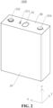
FIG. 2 is a perspective view of an energy-storage device according to an embodiment. -
FIG. 3 is an exploded view of an energy-storage device according to an embodiment. -
FIG. 4 is a front view of an energy-storage device according to an embodiment. -
FIG. 5 is a cross-sectional view ofFIG. 4 , taken along line E-E. -
FIG. 6 is a partial enlarged view at circle Q inFIG. 5 . -
FIG. 7 is a perspective view of a lower plastic assembly according to an embodiment. -
FIG. 8 is an enlarged partial view of an electrode assembly and a tab inFIG. 6 . -
FIG. 9 is a partial enlarged exploded view of the tab and a connector inFIG. 6 . -
FIG. 10 is a schematic diagram of an electricity-consumption apparatus. - Reference numerals are described as follows:
1000 - energy-storage device, 2000 - photovoltaic panel, 3000 - wind turbine, 4000 - power grid, 10 - housing, 20 - electrode assembly, 30 - tab, 31 - first tab, 311 - merging portion, 312 - extension portion, 313 - bent portion, 314 - inclined portion, 315 - connection portion, 32 - second tab, 40 - connector, 41 - first connector, 411 - third surface, 412 - fourth surface, 413 - inclined surface, 42 - second connector, 50 - end cover assembly, 51 - top cover, 511 - electrolyte injection hole, 52 - lower plastic assembly, 521 - first surface, 522 - second surface, 523 - avoidance recess, 53 - terminal post, 531 - first disc body, 532 - first column body, 533 - second disc body, 534 - second column body, 54 - sealing ring, 541 - first sealing ring, 542 - second sealing ring, 55 - explosion-proof valve, 60 - protective film, H1 - first distance, H2 - second distance, A - first included angle, B - second included angle, X - first direction, Y - second direction, Z - third direction, 70 - electricity-consumption apparatus, 80 - electricity-consumption device. - The technical solutions in embodiments of the disclosure are clearly and completely described in the following with reference to the accompanying drawings in the embodiments of the disclosure. Apparently, the described embodiments are merely part of rather than all of the embodiments of the disclosure. All other embodiments obtained by those of ordinary skill in the art based on the embodiments of the disclosure without creative efforts are within the scope of the disclosure.
- It may be noted that when a component is referred to as "fixed to" another component, it may be directly on the another component or there may be an intervening component. When a component is considered "connected to" another component, it may be directly connected to the another component or there may be an intervening component as well.
- Unless otherwise defined, all technical and scientific terms used in the disclosure have the same meaning as commonly understood by those skilled in the art of the disclosure. The terms used in the specification of the disclosure are for merely describing embodiments rather than intending to limit the disclosure. The term "and/or" as used in the disclosure includes any and all combinations of one or more of the associated listed items.
- Some embodiments of the disclosure will be described in detail hereinafter with reference to the accompanying drawings. The embodiments in the disclosure as well as features in the embodiments can be combined with each other without inconsistency.
- Since the energy needed by people is highly temporal and spatial, in order to rationally utilize energy and improve energy efficiency, it is necessary to use a medium or device to store one form of energy, either in its original form or after converting it into another form of energy, and to release it in a specific form based on future application needs. Currently, the generation of green electrical energy generally relies on photovoltaic energy, wind energy, hydropower, etc., but wind energy, solar energy, and the other forms of energy commonly have issues with strong intermittency and large fluctuations, which can lead to grid instability. During peak electricity hours, there may not be enough power, while during off-peak electricity hours, there may be too much. Unstable voltage may also damage the power supply. As a result, problems such as "curtailment of wind and solar power" may arise due to insufficient electricity demand or the grid's limited capacity to accommodate power. To solve these problems, energy-storage is required. Specifically, electrical energy is converted into other forms of energy through physical or chemical means for storage, and when needed, the stored energy is converted back into electrical energy for release. In short, energy-storage is like a large "power bank" that stores electrical energy when photovoltaic energy and wind energy are abundant and releases the electrical energy stored when needed.
- Taking electrochemical energy-storage as an example, this solution provides an energy-storage device, where a set of chemical batteries is disposed in the energy-storage device. Chemical elements in the chemical batteries are mainly used as an energy-storage medium, and a charging and discharging process is accompanied by chemical reactions or changes of the energy-storage medium. In short, electrical energy generated by wind energy and solar energy can be stored in the chemical battery, and when external electricity usage peaks, the electrical energy stored can be released for use, or transferred to areas with insufficient electricity.
- The current application scenarios of energy-storage are relatively extensive, including power-generating-side energy-storage (wind and solar power), power-grid-side energy-storage, base station-side energy-storage, and user-side energy-storage. The corresponding types of energy-storage devices include the following.
- (1) Large-scale energy-storage containers used in grid-side energy-storage scenarios, which can serve as a high-quality active and reactive power regulation power supply in a power grid, realize load matching of electrical energy in time and space, enhance the ability to integrate renewable energy, and are significant in terms of grid system standby, alleviating peak load supply pressure, and peak shaving and frequency regulation.
- (2) Medium and small-sized energy-storage cabinets used in industrial and commercial energy-storage scenarios (banks, shopping malls, etc.) on the user side, which may mainly operate in a "peak shaving and valley filling" mode. Since there is a significant price difference in electricity costs between peak and off-peak electricity hours according to electricity demand, in a case where users have energy-storage devices, the users can typically charge the energy-storage cabinet/box during off-peak electricity hours to reduce costs. During peak electricity hours, the users can discharge the electricity stored in the energy-storage device for use to lower electricity costs.
- A purpose of the disclosure is to provide an energy-storage device and an electricity-
consumption apparatus 70 to address the issue of stress concentration occurring in a tab, which may lead to a decrease in the stability of the electrical connection and a reduction in the reliability of a secondary battery. - To achieve the purpose of the disclosure, the following technical solutions are provided in the disclosure.
- Referring to
FIG. 1 andFIG. 2 . An energy-storage device 1000 provided in the embodiments of the disclosure is applied in an energy-storage system. The energy-storage system includes an energy-storage device 1000, an electric energy conversion device (photovoltaic panel 2000), a wind energy conversion device (wind turbine 3000), and apower grid 4000, among others. The energy-storage device 1000 may serve as an energy-storage cabinet and may be installed outdoors. Specifically, thephotovoltaic panel 2000 may convert solar energy into electrical energy during off-peak electricity hours. The energy-storage device 1000 is used to store this electrical energy and supply it to thepower grid 4000 during peak electricity hours or provide power when thepower grid 4000 is interrupted or out of service. The wind energy conversion device (wind turbine 3000) may convert wind energy into electrical energy, and the energy-storage device 1000 is used to store this electrical energy and supply it to thepower grid 4000 during peak electricity hours or provide power when thepower grid 4000 is interrupted or out of service. The transmission of electrical energy may be carried out using high-voltage cables. - The energy-
storage device 1000 may be implemented as multiple energy-storage devices 1000, and the multiple energy-storage devices 1000 may be connected in series or parallel. The multiple energy-storage devices 1000 may be supported and electrically connected using isolation plates (not illustrated). In this embodiment, "multiple" refers to two or more. An energy-storage box may also be provided externally to accommodate the multiple energy-storage devices 1000. - It may be understood that the energy-
storage device 1000 may include, but is not limited to, individual cells, battery modules, battery packs, battery systems, and so on. The actual application forms of the energy-storage device 1000 provided in the embodiments of the disclosure may be, but are not limited to, the products listed above, and may also include other application forms. The embodiments of the disclosure do not impose strict limitations on the application forms of the energy-storage device 1000. In the embodiments of the disclosure, the energy-storage device 1000 is exemplified by a multi-cell battery. - Referring to
FIG. 1 andFIG. 10 , the embodiments of the disclosure provide the electricity-consumption apparatus 70 that includes an electricity-consumption device 80 and the energy-storage device 1000 described in the embodiments of the disclosure. The energy-storage device 1000 is configured to power the electricity-consumption device 80. The electricity-consumption device 80 may be a power-generating-side electricity-consumption device, a power-grid-side electricity-consumption device, a base-station-side electricity-consumption device, a user-side electricity-consumption device, and so on. The electricity-consumption device 80 may specifically be various types of electrical loads, which is not limited herein. - The energy-
storage device 1000 in the embodiments of the disclosure will be explained in detail below. - Referring to
FIG. 2 andFIG. 3 , the embodiments of the disclosure provide the energy-storage device 1000, which includes ahousing 10, anelectrode assembly 20, atab 30, aconnector 40, anend cover assembly 50, and aprotective film 60. The energy-storage device 1000 is a secondary battery. For ease of explanation, a coordinate system XYZ is established, where first direction Xis a width direction of the energy-storage device 1000, second direction Y is a thickness direction of the energy-storage device 1000, and third direction Z is a height direction of the energy-storage device 1000. First direction X, second direction Y, and third direction Z intersect each other. In the embodiments of the disclosure, first direction X, second direction Y, and third direction Z are perpendicular to each other. - The
housing 10 may be an aluminum shell or a steel shell, and may be in a shape of cuboid. Thehousing 10 defines an accommodating space, and one end of thehousing 10 in the height direction (i.e., third direction Z) has an opening that communicates with the accommodating space. - The
electrode assembly 20 is received in the accommodating space of thehousing 10. Theelectrode assembly 20 may be implemented as one ormore electrode assemblies 20. Theelectrode assembly 20 may have a wound or stacked structure. Theelectrode assembly 20 may include a positive electrode, a negative electrode, and a separator between the positive electrode and the negative electrode, which is not limited herein. In a case where there aremultiple electrode assemblies 20, themultiple electrode assemblies 20 are arranged sequentially in second direction Y. - One end of the
tab 30 is connected to one end of theelectrode assembly 20 corresponding to the opening of the accommodating space, and another end of thetab 30 is connected to theconnector 40. Thetab 30 includes afirst tab 31 and asecond tab 32 with opposite polarities. For example, thefirst tab 31 is apositive tab 30, and thesecond tab 32 is anegative tab 30. Thefirst tab 31 is connected to the positive electrode of theelectrode assembly 20, and thenegative tab 30 is connected to the negative electrode of theelectrode assembly 20. Thetab 30 may be a bendable sheet structure, and may be made of a metal, such as aluminum or copper, which is not limited herein. - The
connector 40 is connected to another end of thetab 30 that is away from theelectrode assembly 20. Theconnector 40 may be a sheet structure, which may be bendable or non-bendable, and may be made of a metal, such as aluminum or copper, which is not limited herein. In a case where there aremultiple electrode assemblies 20, thesame connector 40 may be connected to alltabs 30 of the same polarity ofmultiple electrode assemblies 20. For example, theconnector 40 includes afirst connector 41 and asecond connector 42 with opposite polarities. One of thefirst connector 41 and thesecond connector 42 is apositive connector 40, and another one of thefirst connector 41 and thesecond connector 42 is anegative connector 40. Thefirst tabs 31 of themultiple electrode assemblies 20 are all connected to thefirst connector 41, and thesecond tabs 32 of themultiple electrode assemblies 20 are all connected to thesecond connector 42. - The
end cover assembly 50 is connected to the opening of thehousing 10 and closes the accommodating space. Theend cover assembly 50 is also electrically connected to theconnector 40, allowing theelectrode assembly 20 to be electrically connected to the external environment. - A
protective film 60 may be provided on an outer surface of theelectrode assembly 20. Theprotective film 60 may be an insulating film. Theprotective film 60 protects theelectrode assembly 20 and prevents theelectrode assembly 20 from electrically connecting with an inner wall of thehousing 10. - The
end cover assembly 50 includes atop cover 51, alower plastic assembly 52, aterminal post 53, a sealingring 54, and an explosion-proof valve 55. - The
top cover 51 is a flat plate, which may be an aluminum or steel plate. A length direction of thetop cover 51 is first direction X, a width direction of thetop cover 51 is second direction Y, and a thickness direction of thetop cover 51 is third direction Z. Thetop cover 51 may define various holes, recesses, etc., for installation, which is not limited herein. Thetop cover 51 is used to connect to the opening of thehousing 10 to close the accommodating space. - The
lower plastic assembly 52 may be an integrated plastic member formed by injection molding. A length direction of thelower plastic assembly 52 is first direction X, a width direction of thelower plastic assembly 52 is second direction Y, and a thickness direction of thelower plastic assembly 52 is third direction Z. Thelower plastic assembly 52 has afirst surface 521 and asecond surface 522 opposite thefirst surface 521. Both thefirst surface 521 and thesecond surface 522 may be substantially flat and rectangular. Thefirst surface 521 faces towards thetab 30, and thesecond surface 522 is in close contact with thetop cover 51. Thelower plastic assembly 52 may define recesses, holes, and other structures for installation, which is not limited herein. Thelower plastic assembly 52 is used to space theconnector 40 and thetab 30 apart from thetop cover 51, thereby preventing theconnector 40 and thetab 30 from being in short circuit with thetop cover 51. Thelower plastic assembly 52 is also used for installation of theterminal post 53. - The
terminal post 53 includes a first terminal post and a second terminal post with opposite polarities. The first terminal post is connected to thefirst tab 31, and the second terminal post is connected to thesecond tab 32. The first terminal post and the second terminal post may be of an integrated structure or a separated structure, which is not limited herein. - Optionally, as illustrated in
FIG. 3 , both the first terminal post and the second terminal post are of a separated structure. The first terminal post includes afirst disc body 531 and afirst column body 532, and the second terminal post includes asecond disc body 533 and asecond column body 534. - A radial dimension of the first disc body 531 (i.e., a size of the
first disc body 531 in a radial direction of the first column body 532) is larger than a radial dimension of thefirst column body 532, so that thefirst disc body 531 protrudes from an outer peripheral surface of thefirst column body 532. Thefirst disc body 531 is connected to thefirst connector 41, and both thefirst disc body 531 and thefirst connector 41 are positioned between thelower plastic assembly 52 and theelectrode assembly 20. Thefirst column body 532 extends through thelower plastic assembly 52 and thetop cover 51 to be in connection with thefirst disc body 531, where the first terminal post is exposed to one side of thetop cover 51 away from thelower plastic assembly 52. Both thefirst disc body 531 and thefirst column body 532 are conductive components, which may be made of materials such as copper, aluminum, or copper-aluminum composite. - Similarly, a radial dimension of the second disc body 533 (i.e., a size of the
second disc body 533 in a radial direction of the second column body 534) is larger than a radial dimension of thesecond column body 534, so that thesecond disc body 533 protrudes from an outer peripheral surface of thesecond column body 534. Thesecond disc body 533 is connected to thesecond connector 42, and both thesecond disc body 533 and thesecond connector 42 are located between thelower plastic assembly 52 and theelectrode assembly 20. Thesecond column body 534 extends through thelower plastic assembly 52 and thetop cover 51 to be in connection with thesecond disc body 533, where the second terminal post is exposed to one side of thetop cover 51 away from thelower plastic assembly 52. Both thesecond disc body 533 and thesecond column body 534 are conductive members, which may be made of materials such as copper, aluminum, or copper-aluminum composite. - The sealing
ring 54 includes afirst sealing ring 541 and asecond sealing ring 542. Thefirst sealing ring 541 is sleeved on the outer peripheral surface of thefirst column body 532 and abuts against an inner wall of a hole in thetop cover 51. Thesecond sealing ring 542 is sleeved on the outer peripheral surface of thesecond column body 534 and abuts against an inner wall of a hole in thetop cover 51. Both thefirst sealing ring 541 and thesecond sealing ring 542 may be plastic components, serving to separate thefirst column body 532 from thetop cover 51, and thesecond column body 534 from thetop cover 51, thereby preventing contact between thefirst column body 532 and thetop cover 51, as well as between thesecond column body 534 and thetop cover 51, as such contact would otherwise result in a short circuit between thefirst column body 532 and thesecond column body 534 via thetop cover 51. - The explosion-
proof valve 55 is arranged on thetop cover 51. When theelectrode assembly 20 generates a large amount of gas due to abnormal thermal management and the gas pressure exceeds the threshold of the explosion-proof valve 55, the explosion-proof valve 55 will rupture to release the gas, thereby preventing accidents such as explosions due to trapped gas. - The
end cover assembly 50 also defines anelectrolyte injection hole 511 that extends through thetop cover 51 and thelower plastic assembly 52. Theelectrolyte injection hole 511 is used for electrolyte injection into the accommodating space of thehousing 10. - Referring to
FIGS. 4 to 6 , thefirst surface 521 of thelower plastic assembly 52 defines anavoidance recess 523. At least part of thetab 30 is received within theavoidance recess 523. Theavoidance recess 523 is recessed from thefirst surface 521 and does not penetrate thesecond surface 522, thereby preventing thetab 30 from coming into contact with thetop cover 51 via theavoidance recess 523, as such contact would otherwise result in a short circuit. Theavoidance recess 523 is located at an edge of thelower plastic assembly 52 in the width direction of thelower plastic assembly 52 and extends in the length direction of thelower plastic assembly 52. The specific shape, structure, and dimensions of theavoidance recess 523 are not limited. Similarly, the specific shape and structure of thetab 30 are not limited, as long as at least part of thetab 30 can be received within theavoidance recess 523. - In conventional designs, the
first surface 521 of thelower plastic assembly 52 is substantially flat. When arranging thetab 30, a space between thefirst surface 521 and theelectrode assembly 20 is very narrow, making the arrangement of thetab 30 highly constrained. This can easily lead to stress concentration, thereby reducing the stability of the electrical connection and ultimately affecting the reliability of the secondary battery. Since thetab 30 includes thefirst tab 31 and thesecond tab 32, thefirst surface 521 of thelower plastic assembly 52 may define oneavoidance recess 523 at each of the positions corresponding to thefirst tab 31 and thesecond tab 32, to accommodate at least part of thefirst tab 31 and at least part of thesecond tab 32, respectively. - In the embodiments of the disclosure, the
avoidance recess 523 is defined in thefirst surface 521 of thelower plastic assembly 52 to accommodate at least part of thetab 30, increasing the space available for arranging thetab 30. This ample arrangement space for thetab 30 reduces stress concentration, thereby preventing a decrease in the stability of the electrical connection and ensuring the reliability of the energy-storage device 1000. - In one embodiment, as illustrated in
FIGS. 3 ,6 , and8 , thetab 30 extends in a bent manner. The specific bending shape of thetab 30 is not limited, and the bent extension of thetab 30 facilitates the connection between theelectrode assembly 20 and theconnector 40. - In conventional energy-
storage devices 1000, a limited space for arranging thetab 30 results in an excessively large bending angle, with the bending angle of thetab 30 approaching 180°, leading to significant stress concentration at the bend. - In contrast, in the embodiments of the disclosure, since the
avoidance recess 523 can accommodate at least part of thetab 30, more space is available for bending of thetab 30. This reduces the bending angle of thetab 30, thereby decreasing stress concentration. - Optionally, referring to
FIG. 6 andFIG. 8 , the tab 30 (taking thefirst tab 31 as an example, with thesecond tab 32 being similar) has anextension portion 312, abent portion 313, aninclined portion 314, and aconnection portion 315 that are sequentially connected. One end of theextension portion 312 away from thebent portion 313 is connected to theelectrode assembly 20, one end of theconnection portion 315 away from theinclined portion 314 is connected to theconnector 40, and thebent portion 313 extends in a bent manner and extends into theavoidance recess 523. - Exemplarily, the
extension portion 312 extends in third direction Z, that is, theextension portion 312 extends in a direction from theelectrode assembly 20 to thelower plastic assembly 52. Thebent portion 313 is substantially arc-shaped, where one end of thebent portion 313 is smoothly connected to theextension portion 312 and another end of thebent portion 313 is smoothly connected to theinclined portion 314. Theinclined portion 314 generally extends in a compound direction of first direction X and third direction Z, i.e., theinclined portion 314 is inclined with respect to both first direction X and third direction Z. There is an included angle between theinclined portion 314 and theconnection portion 315. Theextension portion 312, theinclined portion 314, and theconnection portion 315 may each be substantially plate-shaped. Thebent portion 313 represents the highest position of thetab 30 protruding from theelectrode assembly 20. In the embodiments of disclosure, thebent portion 313 is farther away from theelectrode assembly 20 in third direction Z than the rest of thetab 30. - By configuring the
bent portion 313 to extend into theavoidance recess 523, the bending angle of thebent portion 313 can be increased, thereby enlarging the included angle between theinclined portion 314 and theextension portion 312. This prevents the bending angle of thebent portion 313 from being too small, as a too small bending angle would otherwise reduce the included angle between theinclined portion 314 and theextension portion 312 and lead to stress concentration. - Optionally, referring to
FIG. 6 andFIG. 8 , thetab 30 may further have a mergingportion 311. One end of the mergingportion 311 is connected to theelectrode assembly 20, and another end of the mergingportion 311 is connected to one end of theextension portion 312 away from thebent portion 313. An end surface of theelectrode assembly 20 facing thelower plastic assembly 52 may be substantially flat, and multiple tabs 30 (i.e., multiplepositive tabs 30 and multiple negative tabs 30) may be arranged on the same electrode (i.e., either the positive or negative electrode) of theelectrode assembly 20. After winding or stacking, multiple same-polarity tabs 30 on the same electrode may be welded together to form asingle tab 30. Specifically, multiple same-polarity tabs 30, initially spaced apart from each other, are brought close together to form a structure where they are in close contact, and then welded to form a unified structure. This arrangement enables thetab 30 to be electrically connected to various positions within theelectrode assembly 20, thereby enhancing performance. Since themultiple tabs 30 are brought close together to form a unified structure, a cross-section of the mergingportion 311 taken in second direction Y is generally in a shape of triangle, with the base of the triangle is the end face of theelectrode assembly 20 facing thelower plastic assembly 52, and the vertex of the triangle connected to theextension portion 312. In this embodiment, theextension portion 312 is connected to theelectrode assembly 20 via the mergingportion 311, that is, theextension portion 312 is indirectly connected to theelectrode assembly 20. - Optionally, the
electrode assembly 20 may have only onetab 30. In comparison to the embodiment with the mergingportion 311, in this embodiment, theextension portion 312 of thetab 30 is directly connected to theelectrode assembly 20. - Optionally, the
connector 40 is spaced apart from theextension portion 312. This creates a gap between theextension portion 312 and theconnector 40, allowing for the arrangement of theinclined portion 314. - In conventional solutions, an orthographic projection of the
connector 40 in third direction Z substantially coincides with an orthographic projection of thetab 30 in third direction Z. That is, theconnector 40 is located at one side of thetab 30 away from theelectrode assembly 20, completely isolating thetab 30 from thelower plastic assembly 52. This arrangement results in the arrangement space for thetab 30 being limited to a space between theconnector 40 and theelectrode assembly 20. - In contrast, in the embodiments of the disclosure, there is a gap between the
connector 40 and theextension portion 312. Specifically, theconnector 40 has a spacing distance from theextension portion 312 in second direction Y, effectively reducing the size of theconnector 40 in second direction Y. This configuration allows the gap between theextension portion 312 and theconnector 40 to be utilized for the arrangement of thetab 30, thereby expanding the space for the arrangement of thetab 30 and further reducing stress concentration. - In one embodiment, referring to
FIG. 6 andFIG. 8 , one end of theinclined portion 314 connected to thebent portion 313 is spaced apart from theelectrode assembly 20 by a first distance H1, another end of theinclined portion 314 connected to theconnection portion 315 is spaced apart from theelectrode assembly 20 by a second distance H2, and the first distance H1 is greater than the second distance H2. - In this embodiment, the distances from both ends of the
inclined portion 314 to theelectrode assembly 20 refer to the lengths of the perpendicular lines drawn from these ends to the end surface of theelectrode assembly 20 facing thelower plastic assembly 52. - Setting the first distance H1 greater than the second distance H2 allows the one end of the
inclined portion 314 connected to thebent portion 313 to be farther away from theelectrode assembly 20 than the another end of theinclined portion 314 connected to theconnection portion 315. That is, with respect to theelectrode assembly 20 as a reference, the height of the one end of theinclined portion 314 connected to thebent portion 313 is higher, while the height of the another end of theinclined portion 314 connected to theconnection portion 315 is lower. This arrangement allows thebent portion 313 to extend into theavoidance recess 523, while theconnection portion 315 can be easily connected to theconnector 40. - Optionally, referring to
FIGS. 6 ,8, and 9 , the connector 40 (taking thefirst connector 41 as an example) has athird surface 411 and afourth surface 412 opposite thethird surface 411, where thethird surface 411 is opposite to thefirst surface 521, and theconnection portion 315 is connected to thefourth surface 412. - The
third surface 411 and thefourth surface 412 may both be substantially flat. Thethird surface 411 faces towards thefirst surface 521, and thethird surface 411 may be spaced apart or in close contact with thefirst surface 521, which is not limited herein. Thefourth surface 412 faces towards theelectrode assembly 20, and thefourth surface 412 is spaced apart from theelectrode assembly 20. Theconnection portion 315 is connected to thefourth surface 412, making the connection process between thetab 30 and theconnector 40 easier. Specifically, during the connection of thetab 30 and theconnector 40, thetab 30 is first welded to thefourth surface 412, and then thetab 30 is bent and assembled into thehousing 10. Since thefourth surface 412 is exposed, it facilitates the welding process. Based on the connection between theconnection portion 315 and thefourth surface 412, and because there is a gap between thefourth surface 412 and thethird surface 411, there will necessarily be a certain distance between thefourth surface 412 and thelower plastic assembly 52. To allow thebent portion 313 to extend into theavoidance recess 523, theinclined portion 314 is configured as described above, with both ends of theinclined portion 314 positioned at different heights relative to theelectrode assembly 20. - Optionally, referring to
FIGS. 6 ,8, and 9 , the connector 40 (taking thefirst connector 41 as an example, with thesecond connector 42 being similar) has aninclined surface 413, where theinclined surface 413 connects thethird surface 411 to thefourth surface 412, and theinclined surface 413 faces towards theinclined portion 314. - Since one end of the
inclined portion 314 is connected to thebent portion 313, and thebent portion 313 extends into theavoidance recess 523, while theconnection portion 315 is connected to thefourth surface 412, theinclined portion 314 needs to extend from a position substantially flush with thefourth surface 412 to a position substantially flush with thethird surface 411 in a direction from thebent portion 313 to theconnection portion 315. By providing theinclined surface 413 of theconnector 40, which faces towards theinclined portion 314 and serves to allow clearance for theinclined portion 314, thereby providing a greater space for the arrangement of theinclined portion 314 and preventing theinclined portion 314 from contacting an edge corner of theconnection portion 315 and avoiding damage to thetab 30. - Optionally, referring to
FIG. 8 and FIG. 9 , theinclined portion 314 and theconnection portion 315 define a first included angle A, theinclined surface 413 and thefourth surface 412 define a second included angle B, and the first included angle A and the second included angle B satisfy 0° ≤ |A - B| ≤ 30°. - The first included angle A may be greater than, equal to, or less than the second included angle B. The first included angle A may range from 120° to 170°, specifically, it may be 120°, 130°, 135°, 140°, 150°, 160°, 170°, etc., which is not limited herein. The second included angle B may also range from 120° to 170°, specifically, it may be 120°, 130°, 135°, 140°, 150°, 160°, 170°, etc., which is not limited herein.
- The first included angle A and the second included angle B satisfy 0° ≤ |A - B| ≤ 30°, allowing the
inclined portion 314 and theinclined surface 413 to be substantially parallel to each other or to define a small included angle therebetween. This configuration prevents theinclined portion 314 from easily coming into contact with theconnector 40, thereby avoiding stress concentration on thetab 30 caused by the pressure from theconnector 40. - In one embodiment, referring to
FIG. 6 , thetab 30 protrudes beyond thethird surface 411. - In this configuration, at least part of the
bent portion 313 protrudes beyond thethird surface 411, so that thebent portion 313 can extend into theavoidance recess 523. One end of theinclined portion 314 that connects to thebent portion 313 may be flush with thethird surface 411, protrude beyond thethird surface 411, or be positioned between thethird surface 411 and thefourth surface 412. - Such an arrangement allows a space of the
avoidance recess 523 to accommodate at least part of thetab 30, thereby increasing the space for the arrangement of thetab 30 and reducing stress concentration. - In one embodiment, referring to
FIG. 6 , a side wall of theavoidance recess 523 closer to a center of thelower plastic assembly 52 is aligned with a side edge of theconnector 40. - Specifically, an orthographic projection of the side wall of the
avoidance recess 523 closer to the center of thelower plastic assembly 52 on thetop cover 51 at least partially coincides with an orthographic projection of a side edge of theconnector 40 facing theextension portion 312 on thetop cover 51. In this way, the connector in third direction Z does not significantly occupy the space of theavoidance recess 523, allowing sufficient room for the arrangement of thetab 30. - In one embodiment, referring to
FIG. 3 andFIG. 6 , thetab 30 is connected to a side edge of theelectrode assembly 20 in a thickness direction of the electrode assembly 20 (i.e., second direction Y) and extends towards another side edge of theelectrode assembly 20 in the thickness direction of theelectrode assembly 20. - Compared to a configuration where the
tab 30 is connected to a middle region of theelectrode assembly 20 in the thickness direction of theelectrode assembly 20, the embodiments of the disclosure position thetab 30 at the side edge of theelectrode assembly 20 in the thickness direction of theelectrode assembly 20. This allows the middle portion of theelectrode assembly 20, as well as another side edge away from thetab 30, to be free from thetab 30, thereby facilitating the arrangements of other components and enabling more efficient use of limited space. - In one embodiment, referring to
FIGS. 3 and6 , thefirst tab 31 and thesecond tab 32 are spaced apart from each other in the width direction of the electrode assembly 20 (i.e., first direction X), and both thefirst tab 31 and thesecond tab 32 are connected to a same side edge of theelectrode assembly 20 in the thickness direction of theelectrode assembly 20. - This arrangement places both the
first tab 31 and thesecond tab 32 on the same side, thereby also facilitating the arrangements of other components and enabling more efficient use of limited space. - In one embodiment, referring to
FIGS. 3 ,6, and 7 , theelectrode assembly 20 is implemented as twoelectrode assemblies 20, where the twoelectrode assemblies 20 are arranged side by side in the thickness direction of theelectrode assembly 20, and where for each of the twoelectrode assemblies 20, both thefirst tab 31 and thesecond tab 32 are connected to a side edge of theelectrode assembly 20 away from anotherelectrode assembly 20. - For each of the two
electrode assemblies 20, thefirst tab 31 and thesecond tab 32 are connected to the side edge of theelectrode assembly 20 away from anotherelectrode assembly 20. Specifically, for each of the twoelectrode assemblies 20, thefirst tab 31 and thesecond tab 32 connected to theelectrode assembly 20 are positioned on the outer side of theelectrode assembly 20 in second direction Y of theelectrode assembly 20. That is, for each of the twoelectrode assemblies 20, thefirst tab 31 of theelectrode assembly 20 is positioned on a side edge of theelectrode assembly 20 away from anotherelectrode assembly 20, and thesecond tab 32 of theelectrode assembly 20 is also positioned on the side edge of theelectrode assembly 20 away from the anotherelectrode assembly 20. This arrangement provides ample space between the twofirst tabs 31 of the twoelectrode assemblies 20, as well as ample space between the twosecond tabs 32 of the twoelectrode assemblies 20, facilitating the arrangement of other components. - Correspondingly, as illustrated in
FIG. 7 , thelower plastic assembly 52 defines four avoidance recesses 523. The fouravoidance recesses 523 correspond one-to-one with the twofirst tabs 31 and the twosecond tabs 32. - In one embodiment, referring to
FIG. 3 , for each of the twoelectrode assemblies 20, thefirst tab 31 connected to theelectrode assembly 20 is connected to thefirst connector 41, and thesecond tab 32 connected to theelectrode assembly 20 is connected to thesecond connector 42. - By using a single
first connector 41 to connect both the twofirst tabs 31 and a singlesecond connector 42 to connect both the twosecond tabs 32, the number ofconnectors 40 is reduced from four to two compared with a configuration where each tab 30 (i.e., thefirst tab 31 or the second tab 32) is connected to anindependent connector 40. This reduction inconnectors 40 enhances the integration level of theenergy storage device 1000. - It may be understood that terms such as "center", "on", "under", "left", "right", "vertical", "horizontal", "in", "out", and the like referred to herein which indicate directional relationship or positional relationship are directional relationship or positional relationship based on accompanying drawings and are only for the convenience of description and simplicity, rather than explicitly or implicitly indicate that apparatuses or components referred to herein must have a certain direction or be configured or operated in a certain direction and therefore cannot be understood as limitation on the disclosure.
Claims (15)
- An energy-storage device (1000), comprising:an electrode assembly (20);a tab (30), wherein one end of the tab (30) is connected to the electrode assembly (20), and the tab (30) extends in a bent manner;a connector (40) connected to another end of the tab (30); anda lower plastic assembly (52) having a first surface (521) and a second surface (522) opposite the first surface (521), wherein the first surface (521) faces towards the tab (30), the connector (40) is located between the lower plastic assembly (52) and the electrode assembly (20), and an avoidance recess (523) is defined in the first surface (521), wherein the avoidance recess (523) is located at an edge of the lower plastic assembly (52) in a width direction of the lower plastic assembly (52) and extends in a length direction of the lower plastic assembly (52);wherein the tab (30) has an extension portion (312), a bent portion (313), an inclined portion (314), and a connection portion (315) that are sequentially connected, wherein one end of the extension portion (312) away from the bent portion (313) is connected to the electrode assembly (20), one end of the connection portion (315) away from the inclined portion (314) is connected to the connector (40), and the bent portion (313) extends in a bent manner and extends into the avoidance recess (523).
- The energy-storage device (1000) of claim 1, wherein the connector (40) is spaced apart from the extension portion (312).
- The energy-storage device (1000) of claim 1 or 2, wherein one end of the inclined portion (314) connected to the bent portion (313) is spaced apart from the electrode assembly (20) by a first distance (H1), another end of the inclined portion (314) connected to the connection portion (315) is spaced apart from the electrode assembly (20) by a second distance (H2), and the first distance (H1) is greater than the second distance (H2).
- The energy-storage device (1000) of any one of claims 1 to 3, wherein the connector (40) has a third surface (411) and a fourth surface (412) opposite the third surface (411), wherein the third surface (411) is opposite to the first surface (521), and the connection portion (315) is connected to the fourth surface (412).
- The energy-storage device (1000) of claim 4, wherein the connector (40) has an inclined surface (413), wherein the inclined surface (413) connects the third surface (411) to the fourth surface (412), and the inclined surface (413) faces towards the inclined portion (314).
- The energy-storage device (1000) of claim 5, wherein the inclined portion (314) and the connection portion (315) define a first included angle A, the inclined surface (413) and the fourth surface (412) define a second included angle B, and the first included angle A and the second included angle B satisfy 0° ≤ |A - B| ≤ 30°.
- The energy-storage device (1000) of any one of claims 4 to 6, wherein the tab (30) protrudes beyond the third surface (411).
- The energy-storage device (1000) of any one of claims 1 to 7, wherein a side wall of the avoidance recess (523) closer to a center of the lower plastic assembly (52) is aligned with a side edge of the connector (40).
- The energy-storage device (1000) of any one of claims 1 to 8, wherein the tab (30) is connected to a side edge of the electrode assembly (20) in a thickness direction of the electrode assembly (20) and extends towards another side edge of the electrode assembly (20) in the thickness direction of the electrode assembly (20).
- The energy-storage device (1000) of claim 9, wherein the tab (30) comprises a first tab (31) and a second tab (32) of opposite polarities, wherein the first tab (31) and the second tab (32) are spaced apart from each other in a width direction of the electrode assembly (20), and both the first tab (31) and the second tab (32) are connected to a same side edge of the electrode assembly (20) in the thickness direction of the electrode assembly (20).
- The energy-storage device (1000) of claim 10, wherein the electrode assembly (20) is implemented as two electrode assemblies (20), wherein the two electrode assemblies (20) are arranged side by side in the thickness direction of the electrode assembly (20), and wherein for each of the two electrode assemblies (20), both the first tab (31) and the second tab (32) are connected to a side edge of the electrode assembly (20) away from another electrode assembly (20).
- The energy-storage device (1000) of claim 11, wherein the connector (40) comprises a first connector (41) and a second connector (42), wherein for each of the two electrode assemblies (20), the first tab (31) connected to the electrode assembly (20) is connected to the first connector (41), and the second tab (32) connected to the electrode assembly (20) is connected to the second connector (42).
- The energy-storage device (1000) of any one of claims 1 to 12, wherein the bent portion (313) is farther away from the electrode assembly (20), in a direction from the electrode assembly (20) to the lower plastic assembly (52), than the rest of the tab (30).
- The energy-storage device (1000) of any one of claims 1 to 13, wherein an orthographic projection of a side wall of the avoidance recess (523) closer to a center of the lower plastic assembly (52) on the top cover (51) at least partially coincides with an orthographic projection of a side edge of the connector (40) facing the extension portion (312) on the top cover (51).
- An electricity-consumption apparatus (70), comprising an electricity-consumption device (80) and an energy-storage device (1000) of any one of claims 1 to 14, wherein the energy-storage device (1000) is configured to power the electricity-consumption device.
Applications Claiming Priority (1)
| Application Number | Priority Date | Filing Date | Title |
|---|---|---|---|
| CN202420042644.6U CN221978159U (en) | 2024-01-08 | 2024-01-08 | Energy storage device and electric equipment |
Publications (1)
| Publication Number | Publication Date |
|---|---|
| EP4583266A1 true EP4583266A1 (en) | 2025-07-09 |
Family
ID=93317318
Family Applications (1)
| Application Number | Title | Priority Date | Filing Date |
|---|---|---|---|
| EP24221818.8A Pending EP4583266A1 (en) | 2024-01-08 | 2024-12-19 | Energy-storage device and electricity-consumption apparatus |
Country Status (3)
| Country | Link |
|---|---|
| US (1) | US20250226545A1 (en) |
| EP (1) | EP4583266A1 (en) |
| CN (1) | CN221978159U (en) |
Citations (4)
| Publication number | Priority date | Publication date | Assignee | Title |
|---|---|---|---|---|
| US20180013123A1 (en) * | 2015-03-31 | 2018-01-11 | Gs Yuasa International Ltd. | Energy storage device |
| US20200251711A1 (en) * | 2017-02-27 | 2020-08-06 | Sanyo Electric Co., Ltd. | Rectangular secondary battery and method of manufacturing the same |
| EP3770995A1 (en) * | 2018-03-23 | 2021-01-27 | BYD Company Limited | Single-cell battery, battery module, power battery and electric vehicle |
| EP4203174A1 (en) * | 2021-12-21 | 2023-06-28 | Prime Planet Energy & Solutions, Inc. | Secondary battery |
-
2024
- 2024-01-08 CN CN202420042644.6U patent/CN221978159U/en active Active
- 2024-12-19 EP EP24221818.8A patent/EP4583266A1/en active Pending
- 2024-12-20 US US18/989,103 patent/US20250226545A1/en active Pending
Patent Citations (4)
| Publication number | Priority date | Publication date | Assignee | Title |
|---|---|---|---|---|
| US20180013123A1 (en) * | 2015-03-31 | 2018-01-11 | Gs Yuasa International Ltd. | Energy storage device |
| US20200251711A1 (en) * | 2017-02-27 | 2020-08-06 | Sanyo Electric Co., Ltd. | Rectangular secondary battery and method of manufacturing the same |
| EP3770995A1 (en) * | 2018-03-23 | 2021-01-27 | BYD Company Limited | Single-cell battery, battery module, power battery and electric vehicle |
| EP4203174A1 (en) * | 2021-12-21 | 2023-06-28 | Prime Planet Energy & Solutions, Inc. | Secondary battery |
Also Published As
| Publication number | Publication date |
|---|---|
| CN221978159U (en) | 2024-11-08 |
| US20250226545A1 (en) | 2025-07-10 |
Similar Documents
| Publication | Publication Date | Title |
|---|---|---|
| EP4553961A1 (en) | End cover assembly, energy storage device, and electric apparatus | |
| CN116207432B (en) | End cover assembly, energy storage device and electrical equipment | |
| CN117059979B (en) | End cover assembly, energy storage device and electric equipment | |
| CN116544627B (en) | End cover unit, energy storage device and electrical equipment | |
| CN116780067B (en) | Energy storage device and electric equipment | |
| CN116780065B (en) | End cover assembly, energy storage device and electric equipment | |
| CN116470240A (en) | End cap assembly, energy storage device and electrical equipment | |
| US12080866B1 (en) | Energy-storage device, electricity-consumption system, and energy-storage system | |
| CN116759760B (en) | End cover components, energy storage devices and energy storage systems | |
| CN116742229B (en) | Energy storage device and electric equipment | |
| WO2024222071A1 (en) | Current collecting disc, end cover assembly, energy storage device and electric apparatus | |
| CN117039287A (en) | End cover assembly, energy storage device and electric equipment | |
| WO2026081908A1 (en) | Battery, battery module and electrical device | |
| US20250309412A1 (en) | Battery housing, energy storage device, and electricity-consumption device | |
| CN117855709B (en) | End cover assembly, energy storage device and electric equipment | |
| EP4583266A1 (en) | Energy-storage device and electricity-consumption apparatus | |
| CN221928320U (en) | End cover assembly, energy storage device and electrical equipment | |
| CN220086330U (en) | Energy storage device and electric equipment | |
| CN116344834B (en) | Energy storage device and electric equipment | |
| WO2024222074A1 (en) | Energy storage device and electric apparatus | |
| WO2024250804A1 (en) | Energy storage apparatus and electric device | |
| CN116826319A (en) | Energy storage device and electric equipment | |
| EP4734275A1 (en) | End cap assembly, energy storage apparatus and electric device | |
| CN116799391A (en) | Lower plastics, energy storage devices and electrical equipment | |
| CN116315482A (en) | Current collecting disc, end cover assembly, energy storage device and electric equipment |
Legal Events
| Date | Code | Title | Description |
|---|---|---|---|
| PUAI | Public reference made under article 153(3) epc to a published international application that has entered the european phase |
Free format text: ORIGINAL CODE: 0009012 |
|
| STAA | Information on the status of an ep patent application or granted ep patent |
Free format text: STATUS: THE APPLICATION HAS BEEN PUBLISHED |
|
| AK | Designated contracting states |
Kind code of ref document: A1 Designated state(s): AL AT BE BG CH CY CZ DE DK EE ES FI FR GB GR HR HU IE IS IT LI LT LU LV MC ME MK MT NL NO PL PT RO RS SE SI SK SM TR |
|
| STAA | Information on the status of an ep patent application or granted ep patent |
Free format text: STATUS: REQUEST FOR EXAMINATION WAS MADE |
|
| 17P | Request for examination filed |
Effective date: 20251022 |
|
| GRAP | Despatch of communication of intention to grant a patent |
Free format text: ORIGINAL CODE: EPIDOSNIGR1 |
|
| STAA | Information on the status of an ep patent application or granted ep patent |
Free format text: STATUS: GRANT OF PATENT IS INTENDED |
|
| INTG | Intention to grant announced |
Effective date: 20260202 |
|
| GRAS | Grant fee paid |
Free format text: ORIGINAL CODE: EPIDOSNIGR3 |
|
| GRAA | (expected) grant |
Free format text: ORIGINAL CODE: 0009210 |
|
| STAA | Information on the status of an ep patent application or granted ep patent |
Free format text: STATUS: THE PATENT HAS BEEN GRANTED |