EP4583265A1 - Packaging bag, electrochemical apparatus, and electronic device - Google Patents
Packaging bag, electrochemical apparatus, and electronic device Download PDFInfo
- Publication number
- EP4583265A1 EP4583265A1 EP23876707.3A EP23876707A EP4583265A1 EP 4583265 A1 EP4583265 A1 EP 4583265A1 EP 23876707 A EP23876707 A EP 23876707A EP 4583265 A1 EP4583265 A1 EP 4583265A1
- Authority
- EP
- European Patent Office
- Prior art keywords
- pouch
- pouch body
- wall portion
- cavity
- sealing layer
- Prior art date
- Legal status (The legal status is an assumption and is not a legal conclusion. Google has not performed a legal analysis and makes no representation as to the accuracy of the status listed.)
- Pending
Links
Images


Classifications
-
- H—ELECTRICITY
- H01—ELECTRIC ELEMENTS
- H01M—PROCESSES OR MEANS, e.g. BATTERIES, FOR THE DIRECT CONVERSION OF CHEMICAL ENERGY INTO ELECTRICAL ENERGY
- H01M50/00—Constructional details or processes of manufacture of the non-active parts of electrochemical cells other than fuel cells, e.g. hybrid cells
- H01M50/10—Primary casings; Jackets or wrappings
- H01M50/116—Primary casings; Jackets or wrappings characterised by the material
- H01M50/124—Primary casings; Jackets or wrappings characterised by the material having a layered structure
- H01M50/126—Primary casings; Jackets or wrappings characterised by the material having a layered structure comprising three or more layers
-
- H—ELECTRICITY
- H01—ELECTRIC ELEMENTS
- H01G—CAPACITORS; CAPACITORS, RECTIFIERS, DETECTORS, SWITCHING DEVICES, LIGHT-SENSITIVE OR TEMPERATURE-SENSITIVE DEVICES OF THE ELECTROLYTIC TYPE
- H01G9/00—Electrolytic capacitors, rectifiers, detectors, switching devices, light-sensitive or temperature-sensitive devices; Processes of their manufacture
- H01G9/004—Details
- H01G9/08—Housing; Encapsulation
-
- H—ELECTRICITY
- H01—ELECTRIC ELEMENTS
- H01M—PROCESSES OR MEANS, e.g. BATTERIES, FOR THE DIRECT CONVERSION OF CHEMICAL ENERGY INTO ELECTRICAL ENERGY
- H01M10/00—Secondary cells; Manufacture thereof
- H01M10/05—Accumulators with non-aqueous electrolyte
- H01M10/052—Li-accumulators
- H01M10/0525—Rocking-chair batteries, i.e. batteries with lithium insertion or intercalation in both electrodes; Lithium-ion batteries
-
- H—ELECTRICITY
- H01—ELECTRIC ELEMENTS
- H01M—PROCESSES OR MEANS, e.g. BATTERIES, FOR THE DIRECT CONVERSION OF CHEMICAL ENERGY INTO ELECTRICAL ENERGY
- H01M50/00—Constructional details or processes of manufacture of the non-active parts of electrochemical cells other than fuel cells, e.g. hybrid cells
- H01M50/10—Primary casings; Jackets or wrappings
- H01M50/102—Primary casings; Jackets or wrappings characterised by their shape or physical structure
- H01M50/103—Primary casings; Jackets or wrappings characterised by their shape or physical structure prismatic or rectangular
-
- H—ELECTRICITY
- H01—ELECTRIC ELEMENTS
- H01M—PROCESSES OR MEANS, e.g. BATTERIES, FOR THE DIRECT CONVERSION OF CHEMICAL ENERGY INTO ELECTRICAL ENERGY
- H01M50/00—Constructional details or processes of manufacture of the non-active parts of electrochemical cells other than fuel cells, e.g. hybrid cells
- H01M50/10—Primary casings; Jackets or wrappings
- H01M50/102—Primary casings; Jackets or wrappings characterised by their shape or physical structure
- H01M50/105—Pouches or flexible bags
-
- H—ELECTRICITY
- H01—ELECTRIC ELEMENTS
- H01M—PROCESSES OR MEANS, e.g. BATTERIES, FOR THE DIRECT CONVERSION OF CHEMICAL ENERGY INTO ELECTRICAL ENERGY
- H01M50/00—Constructional details or processes of manufacture of the non-active parts of electrochemical cells other than fuel cells, e.g. hybrid cells
- H01M50/10—Primary casings; Jackets or wrappings
- H01M50/116—Primary casings; Jackets or wrappings characterised by the material
- H01M50/117—Inorganic material
- H01M50/119—Metals
-
- H—ELECTRICITY
- H01—ELECTRIC ELEMENTS
- H01M—PROCESSES OR MEANS, e.g. BATTERIES, FOR THE DIRECT CONVERSION OF CHEMICAL ENERGY INTO ELECTRICAL ENERGY
- H01M50/00—Constructional details or processes of manufacture of the non-active parts of electrochemical cells other than fuel cells, e.g. hybrid cells
- H01M50/10—Primary casings; Jackets or wrappings
- H01M50/116—Primary casings; Jackets or wrappings characterised by the material
- H01M50/121—Organic material
-
- H—ELECTRICITY
- H01—ELECTRIC ELEMENTS
- H01M—PROCESSES OR MEANS, e.g. BATTERIES, FOR THE DIRECT CONVERSION OF CHEMICAL ENERGY INTO ELECTRICAL ENERGY
- H01M50/00—Constructional details or processes of manufacture of the non-active parts of electrochemical cells other than fuel cells, e.g. hybrid cells
- H01M50/10—Primary casings; Jackets or wrappings
- H01M50/116—Primary casings; Jackets or wrappings characterised by the material
- H01M50/124—Primary casings; Jackets or wrappings characterised by the material having a layered structure
- H01M50/126—Primary casings; Jackets or wrappings characterised by the material having a layered structure comprising three or more layers
- H01M50/129—Primary casings; Jackets or wrappings characterised by the material having a layered structure comprising three or more layers with two or more layers of only organic material
-
- H—ELECTRICITY
- H01—ELECTRIC ELEMENTS
- H01M—PROCESSES OR MEANS, e.g. BATTERIES, FOR THE DIRECT CONVERSION OF CHEMICAL ENERGY INTO ELECTRICAL ENERGY
- H01M50/00—Constructional details or processes of manufacture of the non-active parts of electrochemical cells other than fuel cells, e.g. hybrid cells
- H01M50/10—Primary casings; Jackets or wrappings
- H01M50/131—Primary casings; Jackets or wrappings characterised by physical properties, e.g. gas permeability, size or heat resistance
- H01M50/133—Thickness
-
- H—ELECTRICITY
- H01—ELECTRIC ELEMENTS
- H01M—PROCESSES OR MEANS, e.g. BATTERIES, FOR THE DIRECT CONVERSION OF CHEMICAL ENERGY INTO ELECTRICAL ENERGY
- H01M50/00—Constructional details or processes of manufacture of the non-active parts of electrochemical cells other than fuel cells, e.g. hybrid cells
- H01M50/10—Primary casings; Jackets or wrappings
- H01M50/172—Arrangements of electric connectors penetrating the casing
- H01M50/174—Arrangements of electric connectors penetrating the casing adapted for the shape of the cells
- H01M50/178—Arrangements of electric connectors penetrating the casing adapted for the shape of the cells for pouch or flexible bag cells
-
- H—ELECTRICITY
- H01—ELECTRIC ELEMENTS
- H01M—PROCESSES OR MEANS, e.g. BATTERIES, FOR THE DIRECT CONVERSION OF CHEMICAL ENERGY INTO ELECTRICAL ENERGY
- H01M50/00—Constructional details or processes of manufacture of the non-active parts of electrochemical cells other than fuel cells, e.g. hybrid cells
- H01M50/10—Primary casings; Jackets or wrappings
- H01M50/183—Sealing members
- H01M50/186—Sealing members characterised by the disposition of the sealing members
-
- H—ELECTRICITY
- H01—ELECTRIC ELEMENTS
- H01M—PROCESSES OR MEANS, e.g. BATTERIES, FOR THE DIRECT CONVERSION OF CHEMICAL ENERGY INTO ELECTRICAL ENERGY
- H01M50/00—Constructional details or processes of manufacture of the non-active parts of electrochemical cells other than fuel cells, e.g. hybrid cells
- H01M50/50—Current conducting connections for cells or batteries
- H01M50/531—Electrode connections inside a battery casing
-
- H—ELECTRICITY
- H01—ELECTRIC ELEMENTS
- H01M—PROCESSES OR MEANS, e.g. BATTERIES, FOR THE DIRECT CONVERSION OF CHEMICAL ENERGY INTO ELECTRICAL ENERGY
- H01M50/00—Constructional details or processes of manufacture of the non-active parts of electrochemical cells other than fuel cells, e.g. hybrid cells
- H01M50/50—Current conducting connections for cells or batteries
- H01M50/543—Terminals
- H01M50/552—Terminals characterised by their shape
- H01M50/553—Terminals adapted for prismatic, pouch or rectangular cells
- H01M50/557—Plate-shaped terminals
-
- H—ELECTRICITY
- H01—ELECTRIC ELEMENTS
- H01M—PROCESSES OR MEANS, e.g. BATTERIES, FOR THE DIRECT CONVERSION OF CHEMICAL ENERGY INTO ELECTRICAL ENERGY
- H01M2220/00—Batteries for particular applications
- H01M2220/30—Batteries in portable systems, e.g. mobile phone, laptop
-
- Y—GENERAL TAGGING OF NEW TECHNOLOGICAL DEVELOPMENTS; GENERAL TAGGING OF CROSS-SECTIONAL TECHNOLOGIES SPANNING OVER SEVERAL SECTIONS OF THE IPC; TECHNICAL SUBJECTS COVERED BY FORMER USPC CROSS-REFERENCE ART COLLECTIONS [XRACs] AND DIGESTS
- Y02—TECHNOLOGIES OR APPLICATIONS FOR MITIGATION OR ADAPTATION AGAINST CLIMATE CHANGE
- Y02E—REDUCTION OF GREENHOUSE GAS [GHG] EMISSIONS, RELATED TO ENERGY GENERATION, TRANSMISSION OR DISTRIBUTION
- Y02E60/00—Enabling technologies; Technologies with a potential or indirect contribution to GHG emissions mitigation
- Y02E60/10—Energy storage using batteries
Definitions
- This application relates to the technical field of electrochemical devices, and in particular, to a pouch, an electrochemical device, and an electronic device.
- a lithium-ion battery electrochemical device
- advantages such as a high operating voltage and a long service life.
- the lithium-ion battery typically includes a pouch and a bare cell.
- an indentation needs to be formed in the pouch so that the bare cell can be placed in the pouch.
- the pouch is usually thick, thereby directly impairing the energy density of lithium-ion battery.
- An objective of this application is to provide an electrochemical device and an electronic device to at least alleviate the technical problem of insufficiency of the energy density of the electrochemical device.
- the second pouch body includes a second wall portion oriented toward the first pouch body, the second wall portion includes a second wall face oriented toward the accommodation cavity and a fourth wall face oriented away from the accommodation cavity, and a thickness of the second wall portion is H2 along a direction from the second wall face to the fourth wall face, satisfying: H2 ⁇ H1.
- the thickness H2 of the second wall portion is set to be less than the thickness H1 of the first wall portion, and the first cavity is created in the relatively thick first pouch body by stamping, thereby not only meeting the requirement on the indentation capability of the pouch, but also increasing the accommodation space of the accommodation cavity.
- the accommodation cavity can accommodate an electrode assembly of a larger size and a larger amount of electrolyte solution, so as to increase the capacity and energy density of the electrochemical device.
- the arrangement in this embodiment can directly reduce the outline dimensions of the pouch to meet the miniaturization and high-energy-density requirements of the electrochemical device.
- the thickness t2 of the second sealing layer is less than the thickness t1 of the first sealing layer, and the second wall portion can be formed on the basis of the first wall portion by thinning the second sealing layer, so that the thickness of the second wall portion is less than the thickness of the first wall portion, thereby increasing the accommodation space of the accommodation cavity.
- the thicknesses falling within the specified range can ensure the hermeticity of the second sealing layer while increasing the accommodation space of the accommodation cavity.
- a junction between the first sealing layer and the second sealing layer satisfies one of the following conditions:
- junction is in the step shape, slope shape, or arc shape causes the junction to take up a relatively small space, and reduces the interference caused by the junction to the electrode assembly.
- the first pouch body includes a first extension portion obtained by extending the first pouch body from one end of the first wall portion toward the second pouch body.
- the first extension portion is connected to a surface of the second wall portion, the surface being away from the accommodation cavity.
- the junction between the first pouch body and the second pouch body is disposed directly on the outer surface without taking up additional space in the accommodation cavity, thereby ensuring a large capacity of the accommodation cavity.
- a length of the second protection layer is less than a length of the second metal layer, and a first notch is formed at an end of the second wall portion by the second metal layer and the second protection layer jointly.
- the first extension portion extends to the first notch, and, at the first notch, the first sealing layer of the first extension portion is connected to the second metal layer of the second wall portion in a stacked manner.
- a width of the stacked connection between the first sealing layer and the second metal layer is W1, satisfying: W1 ⁇ 1.2 mm.
- the width of the stacked connection between the second metal layer and the first sealing layer is relatively small, so that the space occupied by the first metal layer and the first protection layer at the junction is relatively small, thereby meeting the miniaturization requirement of the electrochemical device 100.
- the width W2 of the first notch is greater than the width W1 of the stacked connection, so that a sufficient space is reserved for stacking the second metal layer and the first sealing layer, thereby facilitating the stacked connection between the second metal layer and the first sealing layer.
- the accommodation cavity of the pouch is configured to accommodate an electrode assembly.
- a clearance exists between the first extension portion and the electrode assembly.
- a width of the clearance is W3, satisfying: W2 ⁇ W3.
- the junction is located on a surface of the second wall portion, the surface is away from the accommodation cavity, and, the width W2 of the first notch is less than the width W3 of the clearance, so that the thickness-changed region is located in the clearance between the first extension portion and the electrode assembly without additionally increasing the thickness of the electrochemical device.
- the accommodation cavity of the pouch is configured to accommodate the electrode assembly, and a tab is connected to the electrode assembly.
- the first pouch body includes a first extension portion obtained by extending the first pouch body from one end of the first wall portion toward the second pouch body, and the second pouch body includes a second extension portion obtained by extending the second pouch body from one end of the second wall portion toward the first pouch body. Both the first extension portion and the second extension portion extend to a side of the electrode assembly, the side being away from the tab; and, the first extension portion is connected to the second extension portion on the side of the electrode assembly, the side being away from the tab.
- the first extension portion is connected to the second extension portion on a side of the electrode assembly, the side is away from the tab, and the thickness-changed region at the junction is located in the clearance, thereby preventing the thickness-changed region from taking up additional space in the electrode assembly and reducing the interference caused by the thickness-changed region to the electrode assembly.
- a second cavity is recessed in the second pouch body.
- the second cavity communicates with the first cavity to form the accommodation cavity, thereby increasing the accommodation space of the accommodation cavity.
- the depth of the second cavity is less than the depth of the first cavity, and the second cavity is relatively shallow, thereby ensuring sufficient capability of the second pouch body to form an indentation.
- an embodiment of this application further provides an electronic device.
- the electronic device includes the electrochemical device according to any one of the embodiments of the first aspect.
- references to an "embodiment” herein means that a specific feature, structure or characteristic described with reference to this embodiment may be included in at least one embodiment of this application. Reference to this term in different places in the specification does not necessarily represent the same embodiment, nor does it represent an independent or alternative embodiment in a mutually exclusive relationship with other embodiments. In addition, to the extent that no mutual conflict occurs, the technical features described below in different embodiments of this application may be combined with each other.
- an embodiment of this application discloses a pouch 10 configured to package an electrode assembly 20 and an electrolyte solution of an electrochemical device 100.
- the pouch 10 includes a first pouch body 11 and a second pouch body 12 connected to each other.
- the second pouch body 12 is disposed toward the first pouch body 11.
- the first pouch body 11 and the second pouch body 12 jointly close around to form an accommodation cavity 13.
- Both the electrode assembly 20 and the electrolyte solution (not shown in the drawings) of the electrochemical device 100 may be accommodated in the accommodation cavity 13.
- a first cavity 111 is created in the first pouch body 11.
- the first cavity 111 may be created in the first pouch body 11 by stamping.
- the shape of the first cavity 111 may be a circle, a square, a polygon, or the like, and may be set in line with the shape of the electrode assembly 20.
- the first pouch body 11 includes five sidewalls (not shown in the drawings). The five sidewalls jointly close around to form the first cavity 111.
- the five sidewalls include a first wall portion 112 (that is, the bottom wall of the first cavity 111) oriented toward the second pouch body 12.
- the first wall portion 112 includes a first wall face 112a oriented toward the accommodation cavity 13 and a third wall face 112b oriented away from the accommodation cavity 13.
- the thickness of the first wall portion 112 is H1 along a direction from the third wall face 112b to the first wall face 112a (first direction Z).
- the first pouch body 11 may be in the shape of a flat plate, and is basically consistent in thickness in different parts.
- the thickness of the first wall portion 112 and the thicknesses of the other four sidewalls are still basically consistent (due to the stamping, the thicknesses of the other four sidewalls may be slightly less than the thickness of the first wall portion 112).
- This structure ensures a relatively high capability of the first pouch body 11 to form an indentation.
- the relatively high capability to form an indentation means that the structure is still strong and not prone to deform after an indentation is created in the structure.
- FIG. 2 shows a structure of a first pouch body in which a first cavity is created by stamping
- FIG. 4 shows a structure of a first pouch body 11 in which no first cavity 111 is created by stamping.
- the middle part 113 (the part within the dashed line in FIG. 4 ) of the first pouch body 11 is thin.
- the thin middle part 113 forms a bottom wall of the first cavity 111, that is, forms the first wall portion 112.
- the thickness of the first wall portion 112 is less than the thickness of each of the other four side walls.
- the edge of the middle part 113 (the first wall portion 112) of the first pouch body 11 may be stamped.
- the small thickness of the first wall portion 112 can increase the accommodation space of the first cavity 111.
- the thicknesses of the other four sidewalls are relatively large, thereby ensuring a high capability of the first pouch body 11 to form an indentation.
- the second pouch body 12 is connected to the first pouch body 11, and the second pouch body 12 covers the first cavity 111, so that the first pouch body 11 and the second pouch body 12 jointly close around to form the accommodation cavity 13.
- the second pouch body 12 includes a second wall portion 121 oriented toward the first pouch body 11.
- the second wall portion 121 includes a second wall face 121a oriented toward the accommodation cavity 13 and a fourth wall face 121b oriented away from the accommodation cavity 13.
- a thickness of the second wall portion 121 is H2 along a direction (first direction Z) from the second wall face 121a to the fourth wall face 121b, satisfying: H2 ⁇ H1.
- the thickness H2 of the second wall portion 121 is set to be less than the thickness H1 of the first wall portion 112, thereby increasing the accommodation space of the accommodation cavity 13.
- the accommodation cavity 13 can accommodate an electrode assembly 20 of a larger size and a larger amount of electrolyte solution, so as to meet the requirements of the electrochemical device 100 on a high capacity and a high energy density.
- the arrangement in this embodiment can directly reduce the outline dimensions of the pouch 10 to meet the miniaturization and high-energy-density requirements of the electrochemical device 100.
- the second pouch body 12 is in the shape of a flat plate, the thicknesses of the second pouch body in different parts are basically consistent, the second pouch body 12 is directly connected to the first pouch body 11, and the second pouch body 12 covers the first cavity 111.
- the accommodation space of the first cavity 111 is equal to the accommodation space of the accommodation cavity 13.
- a second cavity 122 is created in the second pouch body 12.
- the second cavity 122 communicates with the first cavity 111 to form the accommodation cavity 13, thereby increasing the accommodation space of the accommodation cavity 13.
- the depth of the second cavity 122 is less than the depth of the first cavity 111, and the second cavity 122 is relatively shallow, thereby ensuring sufficient capability of the second pouch body 12 to form an indentation.
- the middle part (not shown in the drawings) of the second pouch body 12 is relatively thin.
- the middle part of the second pouch body 12 forms a second wall portion 121 oriented toward the first pouch body 11, thereby further increasing the accommodation space of the accommodation cavity 13. Understandably, if the size of the accommodation space of the accommodation cavity 13 remains unchanged, by thinning the second wall portion 121, the overall size of the pouch 10 can be reduced, thereby meeting the miniaturization requirement of the electrochemical device 100.
- the first wall portion 112 includes a first sealing layer 1121, a first metal layer 1122, and a first protection layer 1123 disposed sequentially.
- the first sealing layer 1121, the first metal layer 1122, and the first protection layer 1123 may be stacked and bonded to each other by an adhesive.
- the thickness of the first sealing layer 1121 is t1.
- the second wall portion 121 includes a second sealing layer 1211, a second metal layer 1212, and a second protection layer 1213 disposed sequentially.
- the second sealing layer 1211, the second metal layer 1212, and the second protection layer 1213 may be stacked and bonded to each other by an adhesive.
- the thickness of the second sealing layer 1211 is t2, satisfying: t2 ⁇ t1.
- Both the first protection layer 1123 and the second protection layer 1213 may be made of nylon, which is an inert material that is relatively tough.
- the protection layer disposed on the outermost side not only protects the metal layer, but also isolates the metal layer from external moisture.
- Both the first metal layer 1122 and the second metal layer 1212 may be made of aluminum or stainless steel. Both metal layers (1122, 1212) are relatively dense, thereby not only ensuring sufficient strength of the pouch 10, but also playing a role of moisture isolation to ensure hermeticity of the pouch 10.
- Both the first sealing layer 1121 and the second sealing layer 1211 may be made of a polypropylene material to isolate the metal layers from the electrode assembly 20 and the electrolyte solution in the accommodation cavity 13.
- the first protection layer 1123 and the second protection layer 1213 are of the same thickness, and the first metal layer 1122 and the second metal layer 1212 are of the same thickness.
- the second protection layer 1213 is obtained by extending the first protection layer 1123, and the second metal layer 1212 is obtained by extending the first metal layer 1122.
- the second protection layer 1213 is continuous with the first protection layer 1123 (no junction exists between the second protection layer 1213 and the first protection layer 1123).
- the second metal layer 1212 is continuous with the first metal layer 1122 (no junction exists between the second metal layer 1212 and the first metal layer 1122).
- the thickness t2 of the second sealing layer 1211 is less than the thickness t1 of the first sealing layer 1121, and the second wall portion 121 can be formed on the basis of the first wall portion 112 by thinning the second sealing layer 1211, so that the thickness of the second wall portion 121 is less than the thickness of the first wall portion 112, thereby increasing the accommodation space of the accommodation cavity 13.
- the thicknesses falling within the specified range can ensure the hermeticity of the second sealing layer 1211 while increasing the accommodation space of the accommodation cavity 13.
- the first pouch body 11 may be connected to the second pouch body 12 by an adhesive or by heat-sealing, so as to form a complete pouch 10.
- the first protection layer 1123 of the first wall portion 112 is connected to the second protection layer 1213 of the second wall portion 121
- the first metal layer 1122 is connected to the second metal layer 1212
- the first sealing layer 1121 is connected to the second sealing layer 1211.
- the first pouch body 11 includes a first extension portion 114 obtained by extending the first pouch body from one end of the first wall portion 112 toward the second pouch body 12, and the second pouch body 12 includes a second extension portion 123 obtained by extending the second pouch body from one end of the second wall portion 121 toward the first pouch body 11.
- the first extension portion 114 is obtained by extending the first pouch body from the first wall portion 112
- the first extension portion 114 may be considered to be a part of the first wall portion 112. Therefore, the first extension portion 114 also includes the first sealing layer 1121, the first metal layer 1122, and the first protection layer 1123.
- the second extension portion 123 may be considered to be a part of the second wall portion 121.
- the second extension portion 123 includes the second sealing layer 1211, the second metal layer 1212, and the second protection layer 1213.
- the first protection layer 1123 of the first extension portion 114 is connected to the second protection layer 1213 of the second extension portion 123.
- the first metal layer 1122 of the first extension portion 114 is connected to the second metal layer 1212 of the second extension portion 123.
- the first sealing layer 1121 of the first extension portion 114 is connected to the second sealing layer 1211 of the second extension portion 123.
- an obvious color difference is required at the junction B between the first pouch body 11 and the second pouch body 12.
- An obvious color difference may be set between the first extension portion 114 and the second extension portion 123, for example, by adding a color powder onto the first extension portion 114 or the second extension portion 123, or by adding different color powders onto the first extension portion 114 and the second extension portion 123 respectively.
- the junction B between the first sealing layer 1121 and the second sealing layer 1211 assumes a rugged shape in the accommodation cavity 13.
- the junction B is in a step shape descending from the first sealing layer 1121 toward the second sealing layer 1211; or, the junction B is in a slope shape descending from the first sealing layer 1121 toward the second sealing layer 1211; or, the junction B is in an arc shape that connects the first sealing layer 1121 and the second sealing layer 1211.
- the fact that the junction B is in the step shape, slope shape, or arc shape causes the junction B to take up a relatively small space, and reduces the interference caused by the junction B to the electrode assembly 20.
- a tab 21 is connected to the electrode assembly 20.
- both the first extension portion 114 and the second extension portion 123 extend to a side of the electrode assembly 20, the side being away from the tab 21; and, the first extension portion 114 is connected to the second extension portion 123 on the side of the electrode assembly 20, the side being away from the tab 21.
- a clearance 131 exists between the first extension portion 114 and the electrode assembly 20, and exists between the second extension portion 123 and the electrode assembly. The clearance 131 is configured to accommodate an electrolyte solution.
- the first extension portion 114 is connected to the second extension portion 123 on a side of the electrode assembly 20, the side is away from the tab 21, and the thickness-changed region at the junction B is located in the clearance 131, thereby preventing the thickness-changed region from taking up additional space in the electrode assembly 20 and reducing the interference caused by the thickness-changed region to the electrode assembly 20.
- the second pouch body 12 is in the shape of a flat plate.
- the first pouch body 11 includes a first extension portion 114 obtained by extending the first pouch body from one end of the first wall portion 112 toward the second pouch body 12.
- the first extension portion 114 is connected to a surface of the second wall portion 121, the surface being away from the accommodation cavity 13.
- the junction between the first pouch body 11 and the second pouch body 12 is disposed directly on the outer surface without taking up additional space in the accommodation cavity 13, thereby ensuring a large capacity of the accommodation cavity 13.
- a length of the second protection layer 1213 is less than a length of the second metal layer 1212, and a first notch 124 is formed at an end of the second wall portion 121 (an end close to the first extension portion 114) by the second metal layer 1212 and the second protection layer 1213 jointly.
- the first extension portion 114 may extend from the first wall portion 112 to the first notch 124.
- the first sealing layer 1121 of the first extension portion 114 is connected to the second metal layer 1212 of the second wall portion 121 in a stacked manner.
- a part of the second pouch body 12, which is close to the first extension portion 114, may be stripped of the second protection layer 1213 by laser cleaning or other means, so that the length of the second protection layer 1213 is less than the length of the second metal layer 1212, thereby forming a first notch 124.
- a width of the stacked connection between the first sealing layer 1121 and the second metal layer 1212 is W1, satisfying: W1 ⁇ 1.2 mm.
- the width of the stacked connection between the second metal layer 1212 and the first sealing layer 1121 is relatively small, so that the space occupied by the first metal layer 1122 and the first protection layer 1123 at the junction is relatively small, thereby meeting the miniaturization requirement of the electrochemical device 100.
- the width W2 of the first notch 124 is greater than the width W1 of the stacked connection, so that a sufficient space is reserved for stacking the second metal layer 1212 and the first sealing layer 1121, thereby facilitating the stacked connection between the second metal layer 1212 and the first sealing layer 1121.
- the connection manner may be bonding, heat-sealing, or the like to achieve a good effect of moisture isolation.
- a clearance 131 exists between the first extension portion 114 and the electrode assembly 20, and a width of the clearance 131 is W3, satisfying: W2 ⁇ W3.
- the junction is located on a surface of the second wall portion 121, the surface is away from the accommodation cavity 13, and, the width W2 of the first notch 124 is less than the width W3 of the clearance 131, so that the thickness-changed region is located in the clearance 131 between the first extension portion 114 and the electrode assembly 20 without additionally increasing the thickness of the electrochemical device 100.
- the thickness H2 of the second wall portion 121 is set to be less than the thickness H1 of the first wall portion 112, and the first cavity 111 is created in the relatively thick first pouch body 11 by stamping, thereby not only meeting the requirement on the indentation capability of the pouch 10, but also increasing the accommodation space of the accommodation cavity 13.
- the accommodation cavity 13 can accommodate an electrode assembly 20 of a larger size and a larger amount of electrolyte solution, so as to increase the capacity and energy density of the electrochemical device 100.
- the arrangement in this embodiment can directly reduce the outline dimensions of the pouch 10 to meet the miniaturization and high-energy-density requirements of the electrochemical device 100.
- an embodiment of this application discloses an electrochemical device 100.
- the electrochemical device 100 includes the pouch 10 according to any one of the foregoing embodiments, an electrode assembly 20, and an electrolyte solution (not shown in the drawings). Both the electrode assembly 20 and the electrolyte solution are accommodated in the accommodation cavity 13 of the pouch 10.
- a tab 21 is disposed on the electrode assembly 20. The tab 21 protrudes out of the pouch 10 from between the first pouch body 11 and the second pouch body 12, so as to lead out a positive electrode and a negative electrode of the electrode assembly 20.
- the electrochemical device 100 is a smallest unit that makes up a battery or a battery module, and is a site for conversion between electrical energy and chemical energy.
Landscapes
- Chemical & Material Sciences (AREA)
- Chemical Kinetics & Catalysis (AREA)
- Electrochemistry (AREA)
- General Chemical & Material Sciences (AREA)
- Engineering & Computer Science (AREA)
- Materials Engineering (AREA)
- Manufacturing & Machinery (AREA)
- Power Engineering (AREA)
- Inorganic Chemistry (AREA)
- Microelectronics & Electronic Packaging (AREA)
- Sealing Battery Cases Or Jackets (AREA)
- Battery Mounting, Suspending (AREA)
- Electric Double-Layer Capacitors Or The Like (AREA)
Abstract
Description
- This application claims priority to
Chinese Patent Application No. 202211253187.7, filed with the Chinese Patent Office on October 13, 2022 - This application relates to the technical field of electrochemical devices, and in particular, to a pouch, an electrochemical device, and an electronic device.
- With the development of science and technology, consumer electronic products such as mobile phones and laptops are highly favored by people. As a core component of the electronic products, a lithium-ion battery (electrochemical device) has become a component critical to the development of electronic products by virtue of advantages such as a high operating voltage and a long service life.
- The lithium-ion battery typically includes a pouch and a bare cell. During assembling, an indentation needs to be formed in the pouch so that the bare cell can be placed in the pouch. In order to ensure the capability of forming the indentation, the pouch is usually thick, thereby directly impairing the energy density of lithium-ion battery.
- An objective of this application is to provide an electrochemical device and an electronic device to at least alleviate the technical problem of insufficiency of the energy density of the electrochemical device.
- According to a first aspect of this application, a pouch is provided. The pouch closes around to form an accommodation cavity. The pouch includes a first pouch body and a second pouch body connected to each other. A first cavity is recessed in the first pouch body. The second pouch body covers the first cavity so that the first pouch body and the second pouch body jointly close around to form the accommodation cavity. The first pouch body includes a first wall portion oriented toward the second pouch body. The first wall portion includes a first wall face oriented toward the accommodation cavity and a third wall face oriented away from the accommodation cavity. A thickness of the first wall portion is H1 along a direction from the third wall face to the first wall face. The second pouch body includes a second wall portion oriented toward the first pouch body, the second wall portion includes a second wall face oriented toward the accommodation cavity and a fourth wall face oriented away from the accommodation cavity, and a thickness of the second wall portion is H2 along a direction from the second wall face to the fourth wall face, satisfying: H2 < H1.
- In an embodiment of this application, the thickness H2 of the second wall portion is set to be less than the thickness H1 of the first wall portion, and the first cavity is created in the relatively thick first pouch body by stamping, thereby not only meeting the requirement on the indentation capability of the pouch, but also increasing the accommodation space of the accommodation cavity. In this way, the accommodation cavity can accommodate an electrode assembly of a larger size and a larger amount of electrolyte solution, so as to increase the capacity and energy density of the electrochemical device. Alternatively, because the thickness H2 of the second wall portion is less than the thickness H1 of the first wall portion, the arrangement in this embodiment can directly reduce the outline dimensions of the pouch to meet the miniaturization and high-energy-density requirements of the electrochemical device.
- According to some embodiments of this application, the first wall portion includes a first sealing layer, a first metal layer, and a first protection layer disposed sequentially along a direction from the first wall face to the third wall face, and a thickness of the first sealing layer is t1. the second wall portion includes a second sealing layer, a second metal layer, and a second protection layer disposed sequentially along a direction from the second wall face to the fourth wall face, and a thickness of the second sealing layer is t2, satisfying: t2 < t1. The thickness t2 of the second sealing layer is less than the thickness t1 of the first sealing layer, and the second wall portion can be formed on the basis of the first wall portion by thinning the second sealing layer, so that the thickness of the second wall portion is less than the thickness of the first wall portion, thereby increasing the accommodation space of the accommodation cavity.
- According to some embodiments of this application, the thicknesses satisfy t2 = (0.2 to 0.8) × t1. The thicknesses falling within the specified range can ensure the hermeticity of the second sealing layer while increasing the accommodation space of the accommodation cavity.
- According to some embodiments of this application, the first protection layer is connected to the second protection layer. The first metal layer is connected to the second metal layer. The first sealing layer is connected to the second sealing layer.
- A junction between the first sealing layer and the second sealing layer satisfies one of the following conditions:
- (a) the junction is in a step shape descending from the first sealing layer toward the second sealing layer;
- (b) the junction is in a slope shape descending from the first sealing layer toward the second sealing layer; or
- (c) the junction is in an arc shape that connects the first sealing layer and the second sealing layer.
- The fact that the junction is in the step shape, slope shape, or arc shape causes the junction to take up a relatively small space, and reduces the interference caused by the junction to the electrode assembly.
- According to some embodiments of this application, the first pouch body includes a first extension portion obtained by extending the first pouch body from one end of the first wall portion toward the second pouch body. The first extension portion is connected to a surface of the second wall portion, the surface being away from the accommodation cavity. The junction between the first pouch body and the second pouch body is disposed directly on the outer surface without taking up additional space in the accommodation cavity, thereby ensuring a large capacity of the accommodation cavity.
- According to some embodiments of this application, at an end of the second wall portion, the end being close to the first extension portion, a length of the second protection layer is less than a length of the second metal layer, and a first notch is formed at an end of the second wall portion by the second metal layer and the second protection layer jointly. The first extension portion extends to the first notch, and, at the first notch, the first sealing layer of the first extension portion is connected to the second metal layer of the second wall portion in a stacked manner.
- Further, at the first notch, along a direction from the first sealing layer to the second protection layer: a width of the stacked connection between the first sealing layer and the second metal layer is W1, satisfying: W1 ≤ 1.2 mm. The width of the stacked connection between the second metal layer and the first sealing layer is relatively small, so that the space occupied by the first metal layer and the first protection layer at the junction is relatively small, thereby meeting the miniaturization requirement of the
electrochemical device 100. - A width of the first notch is W2, satisfying: W2 = W1 + (0.5 to 1) mm. The width W2 of the first notch is greater than the width W1 of the stacked connection, so that a sufficient space is reserved for stacking the second metal layer and the first sealing layer, thereby facilitating the stacked connection between the second metal layer and the first sealing layer.
- The accommodation cavity of the pouch is configured to accommodate an electrode assembly. In a state in which the electrode assembly is accommodated in the pouch, a clearance exists between the first extension portion and the electrode assembly. A width of the clearance is W3, satisfying: W2 ≤ W3. The junction is located on a surface of the second wall portion, the surface is away from the accommodation cavity, and, the width W2 of the first notch is less than the width W3 of the clearance, so that the thickness-changed region is located in the clearance between the first extension portion and the electrode assembly without additionally increasing the thickness of the electrochemical device.
- According to some embodiments of this application, the accommodation cavity of the pouch is configured to accommodate the electrode assembly, and a tab is connected to the electrode assembly. The first pouch body includes a first extension portion obtained by extending the first pouch body from one end of the first wall portion toward the second pouch body, and the second pouch body includes a second extension portion obtained by extending the second pouch body from one end of the second wall portion toward the first pouch body. Both the first extension portion and the second extension portion extend to a side of the electrode assembly, the side being away from the tab; and, the first extension portion is connected to the second extension portion on the side of the electrode assembly, the side being away from the tab. The first extension portion is connected to the second extension portion on a side of the electrode assembly, the side is away from the tab, and the thickness-changed region at the junction is located in the clearance, thereby preventing the thickness-changed region from taking up additional space in the electrode assembly and reducing the interference caused by the thickness-changed region to the electrode assembly.
- According to some embodiments of this application, a second cavity is recessed in the second pouch body. The second cavity communicates with the first cavity to form the accommodation cavity, thereby increasing the accommodation space of the accommodation cavity. Along the direction from the first pouch body to the second pouch body, the depth of the second cavity is less than the depth of the first cavity, and the second cavity is relatively shallow, thereby ensuring sufficient capability of the second pouch body to form an indentation.
- According to a second aspect, an embodiment of this application further discloses an electrochemical device. The electrochemical device includes the pouch according to any one of the foregoing embodiments.
- According to a third aspect, an embodiment of this application further provides an electronic device. The electronic device includes the electrochemical device according to any one of the embodiments of the first aspect.
- The foregoing description is merely an overview of the technical solutions of this application. Some specific embodiments of this application are described below illustratively to enable a clearer understanding of the technical solutions of this application, enable implementation of the technical solutions based on the subject-matter hereof, and make the foregoing and other objectives, features, and advantages of this application more evident and comprehensible.
- To describe the technical solutions of the embodiments of this application more clearly, the following outlines the drawings used in the embodiments of this application. Evidently, the drawings outlined below are merely a part of embodiments of this application. A person of ordinary skill in the art may derive other drawings from the outlined drawings.
-
FIG. 1 is a schematic structural diagram of an electrochemical device according to some embodiments of this application; -
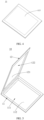
FIG. 2 is an exploded view of an electrochemical device according to some embodiments of this application; -
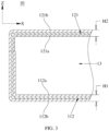
FIG. 3 is a partial cross-sectional view ofFIG. 1 sectioned along an A-A line (without an electrode assembly); -
FIG. 4 is a schematic structural diagram of a first pouch body before an indentation is formed in the first pouch body according to some embodiments of this application; -
FIG. 5 is an exploded view of a pouch according to some embodiments of this application; -
FIG. 6 is a partial cross-sectional view of a pouch according to some embodiments of this application; -
FIG. 7 is a schematic diagram of a junction B between different structures according to some embodiments of this application; -
FIG. 8 is a cross-sectional view of an electrochemical device according to some embodiments of this application; -
FIG. 9 is a partial cross-sectional view of an electrochemical device according to some embodiments of this application; and -
FIG. 10 is a partial schematic structural diagram of a second wall portion according to some embodiments of this application. -
- 100. electrochemical device;
- 10. pouch;
- 11. first pouch body; 111. first cavity; 112. first wall portion; 112a. first wall face; 112b. third wall face; 1121. first sealing layer; 1122. first metal layer; 1123. first protection layer; 113. middle portion; 114. first extension portion;
- 12. second pouch body; 121. second wall portion; 121a. second wall face; 121b. fourth wall face; 1211. second sealing layer; 1212. second metal layer; 1213. second protection layer; 122. second cavity; 123. second extension portion; 124. first notch;
- 13. accommodation cavity; 131. clearance;
- 20. electrode assembly;
- 21: tab.
- For ease of understanding this application, the following describes this application in more detail with reference to drawings and specific embodiments. An element referred to herein as "connected to" another element may be connected to the other element directly or with one or more elements in between. The terms "up", "down", "left", "right", and other similar expressions used herein are merely for ease of description.
- In the description of the embodiments of this application, the technical terms "first" and "second" are merely intended to distinguish between different items but not intended to indicate or imply relative importance or implicitly specify the number of the indicated technical features, specific order, or order of precedence.
- Reference to an "embodiment" herein means that a specific feature, structure or characteristic described with reference to this embodiment may be included in at least one embodiment of this application. Reference to this term in different places in the specification does not necessarily represent the same embodiment, nor does it represent an independent or alternative embodiment in a mutually exclusive relationship with other embodiments. In addition, to the extent that no mutual conflict occurs, the technical features described below in different embodiments of this application may be combined with each other.
- Unless otherwise defined, all technical and scientific terms used herein bear the same meanings as what is normally understood by a person skilled in the technical field of this application. The terms used in the specification of this application are merely intended to describe specific embodiments but not to limit this application.
- According to a first aspect, an embodiment of this application discloses a
pouch 10 configured to package anelectrode assembly 20 and an electrolyte solution of anelectrochemical device 100. Referring toFIG. 1 to FIG. 3 , thepouch 10 includes afirst pouch body 11 and asecond pouch body 12 connected to each other. Thesecond pouch body 12 is disposed toward thefirst pouch body 11. Thefirst pouch body 11 and thesecond pouch body 12 jointly close around to form anaccommodation cavity 13. Both theelectrode assembly 20 and the electrolyte solution (not shown in the drawings) of theelectrochemical device 100 may be accommodated in theaccommodation cavity 13. - For the
first pouch body 11, referring toFIG. 1 andFIG. 2 , afirst cavity 111 is created in thefirst pouch body 11. Thefirst cavity 111 may be created in thefirst pouch body 11 by stamping. The shape of thefirst cavity 111 may be a circle, a square, a polygon, or the like, and may be set in line with the shape of theelectrode assembly 20. Taking a squarefirst cavity 111 as an example, after thefirst cavity 111 is created by stamping, thefirst pouch body 11 includes five sidewalls (not shown in the drawings). The five sidewalls jointly close around to form thefirst cavity 111. The five sidewalls include a first wall portion 112 (that is, the bottom wall of the first cavity 111) oriented toward thesecond pouch body 12. The remaining four sidewalls close around and are connected to thefirst wall portion 112. Referring toFIG. 3 , thefirst wall portion 112 includes afirst wall face 112a oriented toward theaccommodation cavity 13 and athird wall face 112b oriented away from theaccommodation cavity 13. The thickness of thefirst wall portion 112 is H1 along a direction from thethird wall face 112b to thefirst wall face 112a (first direction Z). - Optionally, before the
first cavity 111 is created by stamping, thefirst pouch body 11 may be in the shape of a flat plate, and is basically consistent in thickness in different parts. After thefirst cavity 111 is created by stamping, the thickness of thefirst wall portion 112 and the thicknesses of the other four sidewalls (the thickness in a direction from the inner surface to the outer surface of each sidewall) are still basically consistent (due to the stamping, the thicknesses of the other four sidewalls may be slightly less than the thickness of the first wall portion 112). This structure ensures a relatively high capability of thefirst pouch body 11 to form an indentation. The relatively high capability to form an indentation means that the structure is still strong and not prone to deform after an indentation is created in the structure. - Alternatively, referring to
FIG. 2 andFIG. 4 ,FIG. 2 shows a structure of a first pouch body in which a first cavity is created by stamping, andFIG. 4 shows a structure of afirst pouch body 11 in which nofirst cavity 111 is created by stamping. Before thefirst cavity 111 is created by stamping, the middle part 113 (the part within the dashed line inFIG. 4 ) of thefirst pouch body 11 is thin. After thefirst cavity 111 is created by stamping, the thinmiddle part 113 forms a bottom wall of thefirst cavity 111, that is, forms thefirst wall portion 112. At this time, the thickness of thefirst wall portion 112 is less than the thickness of each of the other four side walls. Because thefirst wall portion 112 is not a part indented directly, the edge of the middle part 113 (the first wall portion 112) of thefirst pouch body 11 may be stamped. The small thickness of thefirst wall portion 112 can increase the accommodation space of thefirst cavity 111. The thicknesses of the other four sidewalls are relatively large, thereby ensuring a high capability of thefirst pouch body 11 to form an indentation. - For the
second pouch body 12, referring toFIG. 2 andFIG. 3 , thesecond pouch body 12 is connected to thefirst pouch body 11, and thesecond pouch body 12 covers thefirst cavity 111, so that thefirst pouch body 11 and thesecond pouch body 12 jointly close around to form theaccommodation cavity 13. Thesecond pouch body 12 includes asecond wall portion 121 oriented toward thefirst pouch body 11. Thesecond wall portion 121 includes asecond wall face 121a oriented toward theaccommodation cavity 13 and afourth wall face 121b oriented away from theaccommodation cavity 13. A thickness of thesecond wall portion 121 is H2 along a direction (first direction Z) from thesecond wall face 121a to thefourth wall face 121b, satisfying: H2 < H1. In this embodiment, the thickness H2 of thesecond wall portion 121 is set to be less than the thickness H1 of thefirst wall portion 112, thereby increasing the accommodation space of theaccommodation cavity 13. In this way, theaccommodation cavity 13 can accommodate anelectrode assembly 20 of a larger size and a larger amount of electrolyte solution, so as to meet the requirements of theelectrochemical device 100 on a high capacity and a high energy density. Alternatively, because the thickness H2 of thesecond wall portion 121 is less than the thickness H1 of thefirst wall portion 112, the arrangement in this embodiment can directly reduce the outline dimensions of thepouch 10 to meet the miniaturization and high-energy-density requirements of theelectrochemical device 100. - Optionally, because the thickness H2 of the
second wall portion 121 is less than the thickness H1 of thefirst wall portion 112, in order to ensure sufficient overall strength of thepouch 10, no indentation needs to be formed in thesecond wall portion 121. For example, thesecond pouch body 12 is in the shape of a flat plate, the thicknesses of the second pouch body in different parts are basically consistent, thesecond pouch body 12 is directly connected to thefirst pouch body 11, and thesecond pouch body 12 covers thefirst cavity 111. The accommodation space of thefirst cavity 111 is equal to the accommodation space of theaccommodation cavity 13. - For another example, referring to
FIG. 5 andFIG. 6 , asecond cavity 122 is created in thesecond pouch body 12. After thesecond pouch body 12 covers thefirst cavity 111, thesecond cavity 122 communicates with thefirst cavity 111 to form theaccommodation cavity 13, thereby increasing the accommodation space of theaccommodation cavity 13. However, in order to sufficient strength of thesecond pouch body 12, along the direction (the first direction Z) from thefirst pouch body 11 to thesecond pouch body 12, the depth of thesecond cavity 122 is less than the depth of thefirst cavity 111, and thesecond cavity 122 is relatively shallow, thereby ensuring sufficient capability of thesecond pouch body 12 to form an indentation. Alternatively, the middle part (not shown in the drawings) of thesecond pouch body 12 is relatively thin. After thesecond cavity 122 is created by stamping, the middle part of thesecond pouch body 12 forms asecond wall portion 121 oriented toward thefirst pouch body 11, thereby further increasing the accommodation space of theaccommodation cavity 13. Understandably, if the size of the accommodation space of theaccommodation cavity 13 remains unchanged, by thinning thesecond wall portion 121, the overall size of thepouch 10 can be reduced, thereby meeting the miniaturization requirement of theelectrochemical device 100. - In some embodiments, referring to
FIG. 6 , along the direction from thefirst wall face 112a to thethird wall face 112b (a direction opposite to the first direction Z), thefirst wall portion 112 includes afirst sealing layer 1121, afirst metal layer 1122, and afirst protection layer 1123 disposed sequentially. Thefirst sealing layer 1121, thefirst metal layer 1122, and thefirst protection layer 1123 may be stacked and bonded to each other by an adhesive. The thickness of thefirst sealing layer 1121 is t1. Along a direction (the first direction Z) from thesecond wall face 121a to thefourth wall face 121b, thesecond wall portion 121 includes asecond sealing layer 1211, asecond metal layer 1212, and asecond protection layer 1213 disposed sequentially. Thesecond sealing layer 1211, thesecond metal layer 1212, and thesecond protection layer 1213 may be stacked and bonded to each other by an adhesive. The thickness of thesecond sealing layer 1211 is t2, satisfying: t2 < t1. - Both the
first protection layer 1123 and thesecond protection layer 1213 may be made of nylon, which is an inert material that is relatively tough. The protection layer disposed on the outermost side not only protects the metal layer, but also isolates the metal layer from external moisture. Both thefirst metal layer 1122 and thesecond metal layer 1212 may be made of aluminum or stainless steel. Both metal layers (1122, 1212) are relatively dense, thereby not only ensuring sufficient strength of thepouch 10, but also playing a role of moisture isolation to ensure hermeticity of thepouch 10. Both thefirst sealing layer 1121 and thesecond sealing layer 1211 may be made of a polypropylene material to isolate the metal layers from theelectrode assembly 20 and the electrolyte solution in theaccommodation cavity 13. Thefirst protection layer 1123 and thesecond protection layer 1213 are of the same thickness, and thefirst metal layer 1122 and thesecond metal layer 1212 are of the same thickness. Optionally, thesecond protection layer 1213 is obtained by extending thefirst protection layer 1123, and thesecond metal layer 1212 is obtained by extending thefirst metal layer 1122. In other words, thesecond protection layer 1213 is continuous with the first protection layer 1123 (no junction exists between thesecond protection layer 1213 and the first protection layer 1123). Thesecond metal layer 1212 is continuous with the first metal layer 1122 (no junction exists between thesecond metal layer 1212 and the first metal layer 1122). The thickness t2 of thesecond sealing layer 1211 is less than the thickness t1 of thefirst sealing layer 1121, and thesecond wall portion 121 can be formed on the basis of thefirst wall portion 112 by thinning thesecond sealing layer 1211, so that the thickness of thesecond wall portion 121 is less than the thickness of thefirst wall portion 112, thereby increasing the accommodation space of theaccommodation cavity 13. - Further, the thicknesses satisfy t2 = (0.2 to 0.8) × t1. The thicknesses falling within the specified range can ensure the hermeticity of the
second sealing layer 1211 while increasing the accommodation space of theaccommodation cavity 13. - In some embodiments, the
first pouch body 11 may be connected to thesecond pouch body 12 by an adhesive or by heat-sealing, so as to form acomplete pouch 10. For example, thefirst protection layer 1123 of thefirst wall portion 112 is connected to thesecond protection layer 1213 of thesecond wall portion 121, thefirst metal layer 1122 is connected to thesecond metal layer 1212, and thefirst sealing layer 1121 is connected to thesecond sealing layer 1211. - Specifically, referring to
FIG. 6 , thefirst pouch body 11 includes afirst extension portion 114 obtained by extending the first pouch body from one end of thefirst wall portion 112 toward thesecond pouch body 12, and thesecond pouch body 12 includes asecond extension portion 123 obtained by extending the second pouch body from one end of thesecond wall portion 121 toward thefirst pouch body 11. Because thefirst extension portion 114 is obtained by extending the first pouch body from thefirst wall portion 112, thefirst extension portion 114 may be considered to be a part of thefirst wall portion 112. Therefore, thefirst extension portion 114 also includes thefirst sealing layer 1121, thefirst metal layer 1122, and thefirst protection layer 1123. Similarly, thesecond extension portion 123 may be considered to be a part of thesecond wall portion 121. Therefore, thesecond extension portion 123 includes thesecond sealing layer 1211, thesecond metal layer 1212, and thesecond protection layer 1213. Thefirst protection layer 1123 of thefirst extension portion 114 is connected to thesecond protection layer 1213 of thesecond extension portion 123. Thefirst metal layer 1122 of thefirst extension portion 114 is connected to thesecond metal layer 1212 of thesecond extension portion 123. Thefirst sealing layer 1121 of thefirst extension portion 114 is connected to thesecond sealing layer 1211 of thesecond extension portion 123. - To facilitate the positioning and connection of the
first pouch body 11 and thesecond pouch body 12, an obvious color difference is required at the junction B between thefirst pouch body 11 and thesecond pouch body 12. An obvious color difference may be set between thefirst extension portion 114 and thesecond extension portion 123, for example, by adding a color powder onto thefirst extension portion 114 or thesecond extension portion 123, or by adding different color powders onto thefirst extension portion 114 and thesecond extension portion 123 respectively. - Due to the thickness difference between the
first sealing layer 1121 and thesecond sealing layer 1211, the junction B between thefirst sealing layer 1121 and thesecond sealing layer 1211 assumes a rugged shape in theaccommodation cavity 13. In order to minimize interference caused by the junction B to theelectrode assembly 20 in theaccommodation cavity 13, in some embodiments, referring to (a), (b), (c), and (d) inFIG. 7 , the junction B is in a step shape descending from thefirst sealing layer 1121 toward thesecond sealing layer 1211; or, the junction B is in a slope shape descending from thefirst sealing layer 1121 toward thesecond sealing layer 1211; or, the junction B is in an arc shape that connects thefirst sealing layer 1121 and thesecond sealing layer 1211. The fact that the junction B is in the step shape, slope shape, or arc shape causes the junction B to take up a relatively small space, and reduces the interference caused by the junction B to theelectrode assembly 20. - Further, referring to
FIG. 8 , atab 21 is connected to theelectrode assembly 20. In a state in which theelectrode assembly 20 is accommodated in theaccommodation cavity 13, both thefirst extension portion 114 and thesecond extension portion 123 extend to a side of theelectrode assembly 20, the side being away from thetab 21; and, thefirst extension portion 114 is connected to thesecond extension portion 123 on the side of theelectrode assembly 20, the side being away from thetab 21. Aclearance 131 exists between thefirst extension portion 114 and theelectrode assembly 20, and exists between thesecond extension portion 123 and the electrode assembly. Theclearance 131 is configured to accommodate an electrolyte solution. In these embodiments, thefirst extension portion 114 is connected to thesecond extension portion 123 on a side of theelectrode assembly 20, the side is away from thetab 21, and the thickness-changed region at the junction B is located in theclearance 131, thereby preventing the thickness-changed region from taking up additional space in theelectrode assembly 20 and reducing the interference caused by the thickness-changed region to theelectrode assembly 20. - In some other embodiments, referring to
FIG. 9 , thesecond pouch body 12 is in the shape of a flat plate. Thefirst pouch body 11 includes afirst extension portion 114 obtained by extending the first pouch body from one end of thefirst wall portion 112 toward thesecond pouch body 12. Thefirst extension portion 114 is connected to a surface of thesecond wall portion 121, the surface being away from theaccommodation cavity 13. In these embodiments, the junction between thefirst pouch body 11 and thesecond pouch body 12 is disposed directly on the outer surface without taking up additional space in theaccommodation cavity 13, thereby ensuring a large capacity of theaccommodation cavity 13. - Specifically, referring to
FIG. 9 andFIG. 10 , at an end of thesecond wall portion 121, the end being close to thefirst extension portion 114, a length of thesecond protection layer 1213 is less than a length of thesecond metal layer 1212, and afirst notch 124 is formed at an end of the second wall portion 121 (an end close to the first extension portion 114) by thesecond metal layer 1212 and thesecond protection layer 1213 jointly. Thefirst extension portion 114 may extend from thefirst wall portion 112 to thefirst notch 124. In addition, at thefirst notch 124, thefirst sealing layer 1121 of thefirst extension portion 114 is connected to thesecond metal layer 1212 of thesecond wall portion 121 in a stacked manner. - A part of the
second pouch body 12, which is close to thefirst extension portion 114, may be stripped of thesecond protection layer 1213 by laser cleaning or other means, so that the length of thesecond protection layer 1213 is less than the length of thesecond metal layer 1212, thereby forming afirst notch 124. At thefirst notch 124, along a direction (second direction X) from thefirst sealing layer 1121 to the second protection layer 1213: a width of the stacked connection between thefirst sealing layer 1121 and thesecond metal layer 1212 is W1, satisfying: W1 ≤ 1.2 mm. The width of the stacked connection between thesecond metal layer 1212 and thefirst sealing layer 1121 is relatively small, so that the space occupied by thefirst metal layer 1122 and thefirst protection layer 1123 at the junction is relatively small, thereby meeting the miniaturization requirement of theelectrochemical device 100. - The width of the removed part of the
first pouch body 11 is W2, that is, the width of thefirst notch 124 is W2, satisfying: W2 = W1 + (0.5 to 1) mm. The width W2 of thefirst notch 124 is greater than the width W1 of the stacked connection, so that a sufficient space is reserved for stacking thesecond metal layer 1212 and thefirst sealing layer 1121, thereby facilitating the stacked connection between thesecond metal layer 1212 and thefirst sealing layer 1121. The connection manner may be bonding, heat-sealing, or the like to achieve a good effect of moisture isolation. - In addition, in a state in which the
electrode assembly 20 is accommodated in theaccommodation cavity 13, aclearance 131 exists between thefirst extension portion 114 and theelectrode assembly 20, and a width of theclearance 131 is W3, satisfying: W2 ≤ W3. In an embodiment of this application, the junction is located on a surface of thesecond wall portion 121, the surface is away from theaccommodation cavity 13, and, the width W2 of thefirst notch 124 is less than the width W3 of theclearance 131, so that the thickness-changed region is located in theclearance 131 between thefirst extension portion 114 and theelectrode assembly 20 without additionally increasing the thickness of theelectrochemical device 100. - In an embodiment of this application, the thickness H2 of the
second wall portion 121 is set to be less than the thickness H1 of thefirst wall portion 112, and thefirst cavity 111 is created in the relatively thickfirst pouch body 11 by stamping, thereby not only meeting the requirement on the indentation capability of thepouch 10, but also increasing the accommodation space of theaccommodation cavity 13. In this way, theaccommodation cavity 13 can accommodate anelectrode assembly 20 of a larger size and a larger amount of electrolyte solution, so as to increase the capacity and energy density of theelectrochemical device 100. Alternatively, because the thickness H2 of thesecond wall portion 121 is less than the thickness H1 of thefirst wall portion 112, the arrangement in this embodiment can directly reduce the outline dimensions of thepouch 10 to meet the miniaturization and high-energy-density requirements of theelectrochemical device 100. - According to a second aspect, an embodiment of this application discloses an
electrochemical device 100. Referring toFIG. 1 ,FIG. 2 , andFIG. 8 , theelectrochemical device 100 includes thepouch 10 according to any one of the foregoing embodiments, anelectrode assembly 20, and an electrolyte solution (not shown in the drawings). Both theelectrode assembly 20 and the electrolyte solution are accommodated in theaccommodation cavity 13 of thepouch 10. Atab 21 is disposed on theelectrode assembly 20. Thetab 21 protrudes out of thepouch 10 from between thefirst pouch body 11 and thesecond pouch body 12, so as to lead out a positive electrode and a negative electrode of theelectrode assembly 20. It is hereby noted that, in this embodiment of this application, theelectrochemical device 100 is a smallest unit that makes up a battery or a battery module, and is a site for conversion between electrical energy and chemical energy. - According to a third aspect, an embodiment of this application further discloses an electronic device. The electronic device includes the
electrochemical device 100 according to any one of the foregoing embodiments. The electronic device is not particularly limited in this application, and may be any electronic device known in the prior art. For example, the electronic device includes, but is not limited to, a Bluetooth headset, a mobile phone, a tablet, a notebook computer, an electric toy, an electric tool, an electric power cart, an electric vehicle, a ship, a spacecraft, and the like. The electric toy may include stationary or mobile electric toys, such as a game console, an electric car toy, an electric ship toy, an electric airplane toy, and the like. The spacecraft may include an airplane, a rocket, a space shuttle, a spaceship, and the like. - It is hereby noted that although preferred embodiments of this application have been given in the specification and drawings of this application, this application may be implemented in many different forms, without being limited to the embodiments described herein. The embodiments are not intended to limit the content of this application, but merely to facilitate thorough and comprehensive understanding of the content disclosed herein. In addition, all kinds of embodiments that are not enumerated above but are derived by further combination of the foregoing technical features still fall within the scope covered by this application. Further, all improvements and variations, which may be made by a person of ordinary skill in the art based on the foregoing description, still fall within the protection scope of the claims appended hereto.
Claims (10)
- A pouch, configured to package an electrode assembly, wherein the pouch closes around to form an accommodation cavity, characterized in that the pouch comprises a first pouch body and a second pouch body connected to each other, and a first cavity is recessed in the first pouch body away from the second pouch body;the second pouch body covers the first cavity so that the first pouch body and the second pouch body jointly close around to form the accommodation cavity; or, a second cavity is recessed in the second pouch body away from the first pouch body, the second cavity communicates with the first cavity to form the accommodation cavity, and a depth of the second cavity is less than a depth of the first cavity along a direction from the first pouch body to the second pouch body;the first pouch body comprises a first wall portion oriented toward the second pouch body, the first wall portion comprises a first wall face oriented toward the accommodation cavity and a third wall face oriented away from the accommodation cavity, and a thickness of the first wall portion is H1 along a direction from the third wall face to the first wall face; andthe second pouch body comprises a second wall portion oriented toward the first pouch body, the second wall portion comprises a second wall face oriented toward the accommodation cavity and a fourth wall face oriented away from the accommodation cavity, and a thickness of the second wall portion is H2 along a direction from the second wall face to the fourth wall face, satisfying: H2 < H1.
- The pouch according to claim 1, characterized in that,the first wall portion comprises a first sealing layer, a first metal layer, and a first protection layer disposed sequentially along a direction from the first sealing layer to the third wall face, and a thickness of the first sealing layer is t1; andthe second wall portion comprises a second sealing layer, a second metal layer, and a second protection layer disposed sequentially along a direction from the second sealing layer to the fourth wall face, and a thickness of the second sealing layer is t2, satisfying: t2 < t1.
- The pouch according to claim 2, characterized in that the thicknesses satisfy: t2 = (0.2 to 0.8) × t1.
- The pouch according to claim 2, characterized in that the first protection layer is connected to the second protection layer, and the first metal layer is connected to the second metal layer; and
the first sealing layer is connected to the second sealing layer, and a junction between the first sealing layer and the second sealing layer satisfies one of the following conditions:a) the junction is in a step shape descending from the first sealing layer toward the second sealing layer;b) the junction is in a slope shape descending from the first sealing layer toward the second sealing layer; orc) the junction is in an arc shape that connects the first sealing layer and the second sealing layer. - The pouch according to claim 2, characterized in that the first pouch body comprises a first extension portion obtained by extending the first pouch body from one end of the first wall portion toward the second pouch body, and the first extension portion is connected to a surface of the second wall portion, the surface being away from the accommodation cavity.
- The pouch according to claim 5, characterized in that,at an end of the second wall portion, the end being close to the first extension portion, a length of the second protection layer is less than a length of the second metal layer, and a first notch is formed at an end of the second wall portion by the second metal layer and the second protection layer jointly; andthe first extension portion extends to the first notch, and, at the first notch, the first sealing layer of the first extension portion is connected to the second metal layer of the second wall portion in a stacked manner.
- The pouch according to claim 6, characterized in that, at the first notch, along a direction from the first sealing layer to the second protection layer:a width of the stacked connection between the first sealing layer and the second metal layer is W1, satisfying: W1 ≤ 1.2 mm;a width of the first notch is W2, satisfying: W2 = W1 + (0.5 to 1) mm; andthe accommodation cavity of the pouch is configured to accommodate an electrode assembly, and, in a state in which the electrode assembly is accommodated in the pouch, a clearance exists between the first extension portion and the electrode assembly, and a width of the clearance is W3, satisfying: W2 ≤ W3.
- The pouch according to claim 2, characterized in that,the accommodation cavity of the pouch is configured to accommodate the electrode assembly, and a tab is connected to the electrode assembly;the first pouch body comprises a first extension portion obtained by extending the first pouch body from one end of the first wall portion toward the second pouch body, and the second pouch body comprises a second extension portion obtained by extending the second pouch body from one end of the second wall portion toward the first pouch body; andboth the first extension portion and the second extension portion extend to a side of the electrode assembly, the side being away from the tab; and, the first extension portion is connected to the second extension portion on the side of the electrode assembly, the side being away from the tab.
- An electrochemical device, characterized in that the electrochemical device comprises the pouch according to any one of claims 1 to 8.
- An electronic device, characterized in that the electronic device comprises the electrochemical device according to claim 9.
Applications Claiming Priority (2)
| Application Number | Priority Date | Filing Date | Title |
|---|---|---|---|
| CN202211253187.7A CN115332691B (en) | 2022-10-13 | 2022-10-13 | Packaging bag, electrochemical device, and electronic apparatus |
| PCT/CN2023/123815 WO2024078505A1 (en) | 2022-10-13 | 2023-10-10 | Packaging bag, electrochemical apparatus, and electronic device |
Publications (2)
| Publication Number | Publication Date |
|---|---|
| EP4583265A1 true EP4583265A1 (en) | 2025-07-09 |
| EP4583265A4 EP4583265A4 (en) | 2026-03-25 |
Family
ID=83913488
Family Applications (1)
| Application Number | Title | Priority Date | Filing Date |
|---|---|---|---|
| EP23876707.3A Pending EP4583265A4 (en) | 2022-10-13 | 2023-10-10 | PACKAGING BAG, ELECTROCHEMICAL DEVICE AND ELECTRONIC DEVICE |
Country Status (4)
| Country | Link |
|---|---|
| US (1) | US20250239692A1 (en) |
| EP (1) | EP4583265A4 (en) |
| CN (1) | CN115332691B (en) |
| WO (1) | WO2024078505A1 (en) |
Families Citing this family (2)
| Publication number | Priority date | Publication date | Assignee | Title |
|---|---|---|---|---|
| CN115332691B (en) * | 2022-10-13 | 2023-03-24 | 宁德新能源科技有限公司 | Packaging bag, electrochemical device, and electronic apparatus |
| CN115498372B (en) * | 2022-11-18 | 2025-05-06 | 宁德新能源科技有限公司 | Electrochemical devices and electronic devices |
Family Cites Families (11)
| Publication number | Priority date | Publication date | Assignee | Title |
|---|---|---|---|---|
| US7048822B2 (en) * | 1999-12-17 | 2006-05-23 | Dai Nippon Printing Co., Ltd. | Packaging material for polymer cell and method for producing the same |
| CN2492044Y (en) * | 2001-04-28 | 2002-05-15 | 莫列斯公司 | Electronic card shell of preventing electromagnetic wave interference |
| CN108428812B (en) * | 2017-02-15 | 2021-02-02 | 宁德新能源科技有限公司 | Packaging shell and laminate polymer battery |
| CN106953032B (en) * | 2017-03-13 | 2020-03-31 | 湖南立方新能源科技有限责任公司 | Lithium ion battery packaging structure and packaging method thereof |
| JP7024540B2 (en) * | 2018-03-22 | 2022-02-24 | Tdk株式会社 | Electrochemical element |
| CN212211080U (en) * | 2020-07-14 | 2020-12-22 | 深圳市锐尔觅移动通信有限公司 | Decoration, shell assembly and electronic equipment |
| CN112510242B (en) * | 2020-11-30 | 2022-04-12 | 东莞新能德科技有限公司 | Secondary battery and terminal device |
| CN217158365U (en) * | 2021-11-11 | 2022-08-09 | 东莞锂微电子科技有限公司 | A button battery and its casing |
| CN217158413U (en) * | 2022-04-12 | 2022-08-09 | 宁德时代新能源科技股份有限公司 | Case of battery cell, battery cell, battery and electric device |
| CN115172950B (en) * | 2022-07-06 | 2024-07-30 | 宁德新能源科技有限公司 | Electrochemical device, electrochemical device assembly, and electronic device |
| CN115332691B (en) * | 2022-10-13 | 2023-03-24 | 宁德新能源科技有限公司 | Packaging bag, electrochemical device, and electronic apparatus |
-
2022
- 2022-10-13 CN CN202211253187.7A patent/CN115332691B/en active Active
-
2023
- 2023-10-10 EP EP23876707.3A patent/EP4583265A4/en active Pending
- 2023-10-10 WO PCT/CN2023/123815 patent/WO2024078505A1/en not_active Ceased
-
2025
- 2025-04-11 US US19/176,401 patent/US20250239692A1/en active Pending
Also Published As
| Publication number | Publication date |
|---|---|
| EP4583265A4 (en) | 2026-03-25 |
| US20250239692A1 (en) | 2025-07-24 |
| WO2024078505A1 (en) | 2024-04-18 |
| CN115332691A (en) | 2022-11-11 |
| CN115332691B (en) | 2023-03-24 |
Similar Documents
| Publication | Publication Date | Title |
|---|---|---|
| US20250239692A1 (en) | Pouch, electrochemical device, and electronic device | |
| EP4498473A1 (en) | Secondary battery and electrical device | |
| EP1524709B1 (en) | Pouch type secondary battery | |
| JP4633528B2 (en) | Lithium ion secondary battery and method for producing lithium ion secondary battery | |
| EP2445048A1 (en) | Rechargeable battery | |
| EP3940854B1 (en) | Electrode assembly, secondary battery, and apparatus using battery | |
| US12431600B2 (en) | Electrode assembly, battery cell, battery, and electrical device | |
| CN114982028A (en) | Secondary battery and method for manufacturing same | |
| CN220895734U (en) | Battery cells, batteries, electrical equipment and energy storage devices | |
| EP4604280A1 (en) | Packaging bag, battery cell, and electrical device | |
| EP4456267A1 (en) | Battery cell and manufacturing method therefor, device, battery, and electric apparatus | |
| US20260051642A1 (en) | Battery cell, battery, and electric device | |
| KR100601510B1 (en) | Pouch-type lithium secondary battery and manufacturing method thereof | |
| WO2025171760A1 (en) | Battery cell, battery, electric device and energy storage apparatus | |
| WO2025097786A1 (en) | Battery cell, battery, and electrical device | |
| EP4546516A1 (en) | Battery cell, battery, and electrical apparatus | |
| US20190296399A1 (en) | Secondary battery | |
| KR100731437B1 (en) | Pouch Type Lithium Secondary Battery | |
| WO2024087327A1 (en) | Case assembly, battery cell, battery and electric device | |
| EP4651252A1 (en) | Battery cell and electrical device | |
| US20260106285A1 (en) | Secondary battery and electronic device including secondary battery | |
| CN222995471U (en) | Batteries and electronic devices | |
| US20260066500A1 (en) | Secondary battery and method of manufacturing the same | |
| EP4726830A1 (en) | Secondary batteries and a manufacturing method thereof | |
| EP4675744A1 (en) | Battery cell, battery, and electric device |
Legal Events
| Date | Code | Title | Description |
|---|---|---|---|
| STAA | Information on the status of an ep patent application or granted ep patent |
Free format text: STATUS: THE INTERNATIONAL PUBLICATION HAS BEEN MADE |
|
| PUAI | Public reference made under article 153(3) epc to a published international application that has entered the european phase |
Free format text: ORIGINAL CODE: 0009012 |
|
| STAA | Information on the status of an ep patent application or granted ep patent |
Free format text: STATUS: REQUEST FOR EXAMINATION WAS MADE |
|
| 17P | Request for examination filed |
Effective date: 20250331 |
|
| AK | Designated contracting states |
Kind code of ref document: A1 Designated state(s): AL AT BE BG CH CY CZ DE DK EE ES FI FR GB GR HR HU IE IS IT LI LT LU LV MC ME MK MT NL NO PL PT RO RS SE SI SK SM TR |
|
| DAV | Request for validation of the european patent (deleted) | ||
| DAX | Request for extension of the european patent (deleted) | ||
| A4 | Supplementary search report drawn up and despatched |
Effective date: 20260223 |
|
| RIC1 | Information provided on ipc code assigned before grant |
Ipc: H01M 50/105 20210101AFI20260217BHEP Ipc: H01M 50/126 20210101ALI20260217BHEP Ipc: H01M 50/557 20210101ALI20260217BHEP Ipc: H01M 50/178 20210101ALI20260217BHEP Ipc: H01G 9/08 20060101ALI20260217BHEP Ipc: H01M 50/183 20210101ALI20260217BHEP Ipc: H01M 50/124 20210101ALI20260217BHEP Ipc: H01M 50/531 20210101ALI20260217BHEP Ipc: H01M 50/133 20210101ALI20260217BHEP Ipc: H01M 50/121 20210101ALI20260217BHEP Ipc: H01M 10/0525 20100101ALI20260217BHEP Ipc: H01M 50/119 20210101ALI20260217BHEP Ipc: H01M 50/186 20210101ALI20260217BHEP Ipc: H01M 50/129 20210101ALI20260217BHEP Ipc: H01M 50/136 20210101ALI20260217BHEP Ipc: H01M 50/103 20210101ALI20260217BHEP Ipc: B65D 75/32 20060101ALI20260217BHEP |