EP4583264A1 - Pouch-type battery case, manufacturing method therefor, and secondary battery manufacturing method - Google Patents
Pouch-type battery case, manufacturing method therefor, and secondary battery manufacturing method Download PDFInfo
- Publication number
- EP4583264A1 EP4583264A1 EP23860845.9A EP23860845A EP4583264A1 EP 4583264 A1 EP4583264 A1 EP 4583264A1 EP 23860845 A EP23860845 A EP 23860845A EP 4583264 A1 EP4583264 A1 EP 4583264A1
- Authority
- EP
- European Patent Office
- Prior art keywords
- gas pocket
- depth
- pocket part
- pouch
- battery case
- Prior art date
- Legal status (The legal status is an assumption and is not a legal conclusion. Google has not performed a legal analysis and makes no representation as to the accuracy of the status listed.)
- Pending
Links
Images






Classifications
-
- H—ELECTRICITY
- H01—ELECTRIC ELEMENTS
- H01M—PROCESSES OR MEANS, e.g. BATTERIES, FOR THE DIRECT CONVERSION OF CHEMICAL ENERGY INTO ELECTRICAL ENERGY
- H01M50/00—Constructional details or processes of manufacture of the non-active parts of electrochemical cells other than fuel cells, e.g. hybrid cells
- H01M50/10—Primary casings; Jackets or wrappings
- H01M50/102—Primary casings; Jackets or wrappings characterised by their shape or physical structure
- H01M50/105—Pouches or flexible bags
-
- B—PERFORMING OPERATIONS; TRANSPORTING
- B29—WORKING OF PLASTICS; WORKING OF SUBSTANCES IN A PLASTIC STATE IN GENERAL
- B29C—SHAPING OR JOINING OF PLASTICS; SHAPING OF MATERIAL IN A PLASTIC STATE, NOT OTHERWISE PROVIDED FOR; AFTER-TREATMENT OF THE SHAPED PRODUCTS, e.g. REPAIRING
- B29C51/00—Shaping by thermoforming, i.e. shaping sheets or sheet like preforms after heating, e.g. shaping sheets in matched moulds or by deep-drawing; Apparatus therefor
- B29C51/10—Forming by pressure difference, e.g. vacuum
-
- H—ELECTRICITY
- H01—ELECTRIC ELEMENTS
- H01M—PROCESSES OR MEANS, e.g. BATTERIES, FOR THE DIRECT CONVERSION OF CHEMICAL ENERGY INTO ELECTRICAL ENERGY
- H01M10/00—Secondary cells; Manufacture thereof
- H01M10/04—Construction or manufacture in general
-
- H—ELECTRICITY
- H01—ELECTRIC ELEMENTS
- H01M—PROCESSES OR MEANS, e.g. BATTERIES, FOR THE DIRECT CONVERSION OF CHEMICAL ENERGY INTO ELECTRICAL ENERGY
- H01M50/00—Constructional details or processes of manufacture of the non-active parts of electrochemical cells other than fuel cells, e.g. hybrid cells
- H01M50/20—Mountings; Secondary casings or frames; Racks, modules or packs; Suspension devices; Shock absorbers; Transport or carrying devices; Holders
- H01M50/247—Mountings; Secondary casings or frames; Racks, modules or packs; Suspension devices; Shock absorbers; Transport or carrying devices; Holders specially adapted for portable devices, e.g. mobile phones, computers, hand tools or pacemakers
-
- B—PERFORMING OPERATIONS; TRANSPORTING
- B29—WORKING OF PLASTICS; WORKING OF SUBSTANCES IN A PLASTIC STATE IN GENERAL
- B29C—SHAPING OR JOINING OF PLASTICS; SHAPING OF MATERIAL IN A PLASTIC STATE, NOT OTHERWISE PROVIDED FOR; AFTER-TREATMENT OF THE SHAPED PRODUCTS, e.g. REPAIRING
- B29C2791/00—Shaping characteristics in general
- B29C2791/004—Shaping under special conditions
-
- B—PERFORMING OPERATIONS; TRANSPORTING
- B29—WORKING OF PLASTICS; WORKING OF SUBSTANCES IN A PLASTIC STATE IN GENERAL
- B29C—SHAPING OR JOINING OF PLASTICS; SHAPING OF MATERIAL IN A PLASTIC STATE, NOT OTHERWISE PROVIDED FOR; AFTER-TREATMENT OF THE SHAPED PRODUCTS, e.g. REPAIRING
- B29C51/00—Shaping by thermoforming, i.e. shaping sheets or sheet like preforms after heating, e.g. shaping sheets in matched moulds or by deep-drawing; Apparatus therefor
- B29C51/14—Shaping by thermoforming, i.e. shaping sheets or sheet like preforms after heating, e.g. shaping sheets in matched moulds or by deep-drawing; Apparatus therefor using multilayered preforms or sheets
-
- B—PERFORMING OPERATIONS; TRANSPORTING
- B29—WORKING OF PLASTICS; WORKING OF SUBSTANCES IN A PLASTIC STATE IN GENERAL
- B29C—SHAPING OR JOINING OF PLASTICS; SHAPING OF MATERIAL IN A PLASTIC STATE, NOT OTHERWISE PROVIDED FOR; AFTER-TREATMENT OF THE SHAPED PRODUCTS, e.g. REPAIRING
- B29C51/00—Shaping by thermoforming, i.e. shaping sheets or sheet like preforms after heating, e.g. shaping sheets in matched moulds or by deep-drawing; Apparatus therefor
- B29C51/26—Component parts, details or accessories; Auxiliary operations
- B29C51/30—Moulds
-
- B—PERFORMING OPERATIONS; TRANSPORTING
- B29—WORKING OF PLASTICS; WORKING OF SUBSTANCES IN A PLASTIC STATE IN GENERAL
- B29K—INDEXING SCHEME ASSOCIATED WITH SUBCLASSES B29B, B29C OR B29D, RELATING TO MOULDING MATERIALS OR TO MATERIALS FOR MOULDS, REINFORCEMENTS, FILLERS OR PREFORMED PARTS, e.g. INSERTS
- B29K2305/00—Use of metals, their alloys or their compounds, as reinforcement
- B29K2305/02—Aluminium
-
- B—PERFORMING OPERATIONS; TRANSPORTING
- B29—WORKING OF PLASTICS; WORKING OF SUBSTANCES IN A PLASTIC STATE IN GENERAL
- B29L—INDEXING SCHEME ASSOCIATED WITH SUBCLASS B29C, RELATING TO PARTICULAR ARTICLES
- B29L2031/00—Other particular articles
- B29L2031/34—Electrical apparatus, e.g. sparking plugs or parts thereof
- B29L2031/3468—Batteries, accumulators or fuel cells
-
- B—PERFORMING OPERATIONS; TRANSPORTING
- B29—WORKING OF PLASTICS; WORKING OF SUBSTANCES IN A PLASTIC STATE IN GENERAL
- B29L—INDEXING SCHEME ASSOCIATED WITH SUBCLASS B29C, RELATING TO PARTICULAR ARTICLES
- B29L2031/00—Other particular articles
- B29L2031/712—Containers; Packaging elements or accessories, Packages
- B29L2031/7146—Battery-cases
-
- Y—GENERAL TAGGING OF NEW TECHNOLOGICAL DEVELOPMENTS; GENERAL TAGGING OF CROSS-SECTIONAL TECHNOLOGIES SPANNING OVER SEVERAL SECTIONS OF THE IPC; TECHNICAL SUBJECTS COVERED BY FORMER USPC CROSS-REFERENCE ART COLLECTIONS [XRACs] AND DIGESTS
- Y02—TECHNOLOGIES OR APPLICATIONS FOR MITIGATION OR ADAPTATION AGAINST CLIMATE CHANGE
- Y02E—REDUCTION OF GREENHOUSE GAS [GHG] EMISSIONS, RELATED TO ENERGY GENERATION, TRANSMISSION OR DISTRIBUTION
- Y02E60/00—Enabling technologies; Technologies with a potential or indirect contribution to GHG emissions mitigation
- Y02E60/10—Energy storage using batteries
-
- Y—GENERAL TAGGING OF NEW TECHNOLOGICAL DEVELOPMENTS; GENERAL TAGGING OF CROSS-SECTIONAL TECHNOLOGIES SPANNING OVER SEVERAL SECTIONS OF THE IPC; TECHNICAL SUBJECTS COVERED BY FORMER USPC CROSS-REFERENCE ART COLLECTIONS [XRACs] AND DIGESTS
- Y02—TECHNOLOGIES OR APPLICATIONS FOR MITIGATION OR ADAPTATION AGAINST CLIMATE CHANGE
- Y02P—CLIMATE CHANGE MITIGATION TECHNOLOGIES IN THE PRODUCTION OR PROCESSING OF GOODS
- Y02P70/00—Climate change mitigation technologies in the production process for final industrial or consumer products
- Y02P70/50—Manufacturing or production processes characterised by the final manufactured product
Definitions
- the present invention relates to a pouch-type battery case, a method of manufacturing the same, and a method of manufacturing a secondary battery using the pouch-type battery case.
- secondary batteries are chargeable and dischargeable unlike primary batteries that are not chargeable and are widely used in electronic devices such as mobile phones, notebook computers, camcorders, and the like, electric vehicles, or the like.
- a lithium secondary battery has larger capacity than a nickel-cadmium battery or a nickel-hydrogen battery and has a high energy density per unit weight, a degree of its utilization is rapidly increasing.
- Secondary batteries may be classified by types of battery case, and representative examples of the secondary batteries may include can-type secondary batteries including cylindrical or prismatic battery cases, and pouch-type secondary batteries including pouch-type battery cases.
- Such a pouch-type battery case may be provided with a cup part that accommodates an electrode assembly and a gas pocket part that collects a gas.
- the gas pocket part may be drawn and molded using a forming device, like the cup part in which the electrode assembly is accommodated.
- a method of manufacturing the pouch-type secondary battery may include a process of sealing a portion of the pouch-type battery case in a state in which the electrode assembly is accommodated in the cup part, a process of injecting an electrolyte through a non-sealed opening of the pouch-type battery case, and a process of activating the electrode assembly through charging and discharging.
- a gas generated in the activation process may be collected in the gas pocket part.
- the process of sealing the opening may be generally performed in a negative pressure chamber (e.g., a vacuum chamber).
- a negative pressure chamber e.g., a vacuum chamber
- the gas pocket part may not be maintained in its shape and may be crushed or deformed due to the negative pressure.
- the gas pocket part is distorted or deformed, since a volume of the gas pocket part decreases, there is a problem in that a gas is not sufficiently collected, and thus, improvement is required.
- One object of the present invention for solving the above problem is to provide a pouch-type battery case that is capable of preventing a gas pocket part from being crushed by a wrinkle part disposed on a gas pocket part and sufficiently collecting a large amount of gas, and a method for manufacturing the same.
- a pouch-type battery case may include: a cup part having a recessed shape; and a gas pocket part disposed at one side of the cup part and having a recessed shape.
- a wrinkle part which is folded or unfolded depending on an internal pressure of the gas pocket part so that a depth of the gas pocket part varies, may be formed on a circumferential portion of the gas pocket part.
- the wrinkle part may include: a convex portion protruding toward the outside of the gas pocket part; and a concave portion which is alternately disposed with the convex portion in a depth direction of the gas pocket part.
- a remaining thickness of the convex portion may be less than a remaining thickness of the concave portion.
- a depth of the gas pocket part may vary between a contracted depth and an expanded depth that is greater than the contracted depth, and wherein the expanded depth may be 0.7 times to 1.3 times a depth of the cup part.
- a depth of the gas pocket part may vary between a contracted depth and an expanded depth that is greater than the contracted depth, and wherein the expanded depth may be 12 times or more than the contracted depth.
- a method for manufacturing a pouch-type battery case may include: molding a cup part and a gas pocket part in a pouch sheet; and molding a wrinkle part, which is folded or unfolded depending on an internal pressure of the gas pocket part so that a depth of the gas pocket part varies, on a circumferential portion of the gas pocket part.
- the wrinkle part may include: a convex portion protruding toward the outside of the gas pocket part; and a concave portion which is alternately disposed with the convex portion in a depth direction of the gas pocket part.
- a remaining thickness of the convex portion may be less than a remaining thickness of the concave portion.
- the gas pocket part, on which the wrinkle part is molded may have an initial depth, and the depth of the gas pocket part may vary between a contracted depth, which is less than the initial depth, and an expanded depth, which is greater than the initial depth.
- the contracted depth may be 0.1 times or less than the initial depth.
- a device for molding the wrinkle part may include: a plurality of support parts that are in contact with an outer circumference of the gas pocket part and disposed at predetermined intervals in a depth direction of the gas pocket part; and a negative pressure part configured to apply a negative pressure to the outer circumference of the gas pocket part through gaps between the plurality of support parts.
- FIGS. 2 to 5 the first case 101 illustrated in FIG. 1 is illustrated in FIGS. 2 to 5 .
- the wrinkle part 121 may have a bellows shape.
- the wrinkle part 121 may include a convex portion 122 that protrudes toward the outside of the gas pocket part 120 and a concave portion 123 disposed alternately with the convex portions 122 in the depth direction of the gas pocket part 120.
- the gas pocket part 120 may have the expanded depth d3.
- the wrinkle part 121 may be expanded due to the internal pressure of a gas generated by the activation process, so that the gas pocket part 120 have the expanded depth d3.
- the expanded depth d3 may be greater than the contracted depth d1.
- the expanded depth d3 may be greater than the initial depth d1.
- the expanded depth d3 may be 1.2 times to 1.3 times the initial depth d1. That is, the expanded depth d3 may be 12 times or more than the contracted depth d2. If the expanded depth d3 is less than 1.2 times the initial depth d1, there is a risk that the wrinkle part 121 is not sufficiently deformed, and the gas is not sufficiently collected in the gas pocket part 120.
- the expanded depth d3 of the gas pocket part 120 may be 0.7 times to 1.3 times the depth d of the cup part 110. If the expanded depth d3 is less than 0.7 times the depth d of the cup part 110, there is a risk that gas is not sufficiently collected in the gas pocket part 120. Conversely, if the expanded depth d3 is greater than 1.3 times the depth d of the cup part 110, a volume of the gas pocket part 120 may be unnecessarily large, and when molding the gas pocket part 120, the pouch sheet 137 may be excessively elongated to cause the cracks.
- the wrinkle part 121 may prevent the gas pocket part 120 from being crushed by the negative pressure and may increase an amount of gas collected by the gas pocket part 120 to improve stability in the activation process.
- FIG. 6 is a schematic view illustrating a device for molding a wrinkle part according to an embodiment of the present invention.
- FIG. 6 illustrates the gas pocket part 120 before the wrinkle part 121 (see FIG. 3 ) is formed.
- a device 10 for molding the wrinkle part 121 on the circumferential portion of the gas pocket part 120 (hereinafter, referred to as a wrinkle molding device) may apply a negative pressure to the outside of the circumferential portion of the gas pocket part 120 to mold the wrinkle part 121.
- the wrinkle molding device 10 may include a plurality of support parts 11 that are in contact with an outer circumference of the gas pocket part 120 and disposed at a predetermined interval in the depth direction of the gas pocket part 120, and a negative pressure part 12 that applies a negative pressure to the outer circumference of the gas pocket part 120 through a gap g between the plurality of support parts 11.
- Each of the plurality of support parts 11 may surround the outer circumference of the gas pocket part 120.
- the plurality of support parts 11 may be in contact with the outer circumference of the gas pocket part 120 at predetermined intervals in the depth direction of the gas pocket part 120.
- each of the plurality of support parts 11 may support the outer circumference of the gas pocket part 120.
- an inner end of the support part 122 may be formed to be rounded.
- a portion of the circumferential portion of the gas pocket part 120, which faces the gap g, may be elongated outward by the negative pressure.
- the portion of the circumferential portion of the gas pocket part 120, which faces the gap g, may be elongated and molded into the convex portion 122 (see FIG. 3 ), and the portion that is in contact with the support part 11 may form the concave portion 123.
- the remaining thickness t1 of the convex portion 122 may be less than the remaining thickness t2 of the concave portion 123.
- the wrinkle part 122 may be easily and quickly molded by the wrinkle molding device 10.
- the gas pocket part 120 in which the wrinkle part 121 is formed may have an initial depth d1. That is, in the case preparation process (S10), the gas pocket part 120 may be molded to the initial depth d1.
- the sealing process (S30) may be performed in a state in which the battery case 100 is disposed in a negative pressure chamber (not shown) (e.g., a vacuum chamber). As a result, the battery case 100 may be sealed in a state in which any gas or air remaining in the battery case 100 is removed.
- a negative pressure chamber not shown
- the battery case 100 may be sealed in a state in which any gas or air remaining in the battery case 100 is removed.
- the depth of the gas pocket part 120 may vary to an expanded depth d3 that is greater than the initial depth d1. That is, as the internal pressure of the gas pocket part 120 increases due to the collected gas, the wrinkle part 121 may be expanded, and the depth of the gas pocket part 120 may increase. As a result, the gas pocket part 120 may stably collect a sufficiently large amount of gas.
- the battery case 100 may be cut along a virtual cutting line CL disposed on the third sealing part 163 or outside the third sealing part 163. As a result, a portion of the battery case 100 including the gas pocket part 120 may be removed.
Landscapes
- Chemical & Material Sciences (AREA)
- Chemical Kinetics & Catalysis (AREA)
- Electrochemistry (AREA)
- General Chemical & Material Sciences (AREA)
- Engineering & Computer Science (AREA)
- Mechanical Engineering (AREA)
- Manufacturing & Machinery (AREA)
- Life Sciences & Earth Sciences (AREA)
- Biophysics (AREA)
- Computer Hardware Design (AREA)
- Sealing Battery Cases Or Jackets (AREA)
- Gas Exhaust Devices For Batteries (AREA)
Abstract
Description
- The present application claims the benefit of the priority of
Korean Patent Application No. 10-2022-0108708, filed on August 29, 2022 - The present invention relates to a pouch-type battery case, a method of manufacturing the same, and a method of manufacturing a secondary battery using the pouch-type battery case.
- In general, secondary batteries are chargeable and dischargeable unlike primary batteries that are not chargeable and are widely used in electronic devices such as mobile phones, notebook computers, camcorders, and the like, electric vehicles, or the like. Particularly, since a lithium secondary battery has larger capacity than a nickel-cadmium battery or a nickel-hydrogen battery and has a high energy density per unit weight, a degree of its utilization is rapidly increasing.
- Secondary batteries may be classified by types of battery case, and representative examples of the secondary batteries may include can-type secondary batteries including cylindrical or prismatic battery cases, and pouch-type secondary batteries including pouch-type battery cases.
- Such a pouch-type battery case may be provided with a cup part that accommodates an electrode assembly and a gas pocket part that collects a gas. The gas pocket part may be drawn and molded using a forming device, like the cup part in which the electrode assembly is accommodated.
- In more detail, a method of manufacturing the pouch-type secondary battery may include a process of sealing a portion of the pouch-type battery case in a state in which the electrode assembly is accommodated in the cup part, a process of injecting an electrolyte through a non-sealed opening of the pouch-type battery case, and a process of activating the electrode assembly through charging and discharging. In addition, a gas generated in the activation process may be collected in the gas pocket part.
- In order to prevent an unnecessary gas or air from remaining in the pouch-type battery case, the process of sealing the opening may be generally performed in a negative pressure chamber (e.g., a vacuum chamber).
- However, unlike the cup part in which the electrode assembly is accommodated, the gas pocket part may not be maintained in its shape and may be crushed or deformed due to the negative pressure. When the gas pocket part is distorted or deformed, since a volume of the gas pocket part decreases, there is a problem in that a gas is not sufficiently collected, and thus, improvement is required.
- One object of the present invention for solving the above problem is to provide a pouch-type battery case that is capable of preventing a gas pocket part from being crushed by a wrinkle part disposed on a gas pocket part and sufficiently collecting a large amount of gas, and a method for manufacturing the same.
- Another object of the present invention is to provide a method for manufacturing a secondary battery including the pouch-type battery case.
- A pouch-type battery case according to an embodiment of the present invention may include: a cup part having a recessed shape; and a gas pocket part disposed at one side of the cup part and having a recessed shape. A wrinkle part, which is folded or unfolded depending on an internal pressure of the gas pocket part so that a depth of the gas pocket part varies, may be formed on a circumferential portion of the gas pocket part. The wrinkle part may include: a convex portion protruding toward the outside of the gas pocket part; and a concave portion which is alternately disposed with the convex portion in a depth direction of the gas pocket part. A remaining thickness of the convex portion may be less than a remaining thickness of the concave portion.
- A depth of the gas pocket part may vary between a contracted depth and an expanded depth that is greater than the contracted depth, and wherein the expanded depth may be 0.7 times to 1.3 times a depth of the cup part.
- A depth of the gas pocket part may vary between a contracted depth and an expanded depth that is greater than the contracted depth, and wherein the expanded depth may be 12 times or more than the contracted depth.
- A method for manufacturing a pouch-type battery case according to an embodiment of the present invention may include: molding a cup part and a gas pocket part in a pouch sheet; and molding a wrinkle part, which is folded or unfolded depending on an internal pressure of the gas pocket part so that a depth of the gas pocket part varies, on a circumferential portion of the gas pocket part. The wrinkle part may include: a convex portion protruding toward the outside of the gas pocket part; and a concave portion which is alternately disposed with the convex portion in a depth direction of the gas pocket part. A remaining thickness of the convex portion may be less than a remaining thickness of the concave portion.
- The gas pocket part, on which the wrinkle part is molded, may have an initial depth, and the depth of the gas pocket part may vary between a contracted depth, which is less than the initial depth, and an expanded depth, which is greater than the initial depth.
- The contracted depth may be 0.1 times or less than the initial depth.
- The expanded depth may be 1.2 times to 1.3 times the initial depth.
- A device for molding the wrinkle part may include: a plurality of support parts that are in contact with an outer circumference of the gas pocket part and disposed at predetermined intervals in a depth direction of the gas pocket part; and a negative pressure part configured to apply a negative pressure to the outer circumference of the gas pocket part through gaps between the plurality of support parts.
- A method for manufacturing a secondary battery according to an embodiment of the present invention may include: preparing a pouch-type battery case; accommodating an electrode assembly and an electrolyte in a cup part of the pouch-type battery case; sealing the pouch-type battery case within a negative pressure chamber; and collecting a gas generated by charging and discharging the electrode assembly into a gas pocket part of the pouch-type battery case. The preparing of the pouch-type battery case may include: molding the cup part and the gas pocket part in a pouch sheet; and molding a wrinkle part, which is folded or unfolded depending on an internal pressure of the gas pocket part so that a depth of the gas pocket part varies, on a circumferential portion of the gas pocket part. The wrinkle part may include: a convex portion protruding toward the outside of the gas pocket part; and a concave portion which is alternately disposed with the convex portion in a depth direction of the gas pocket part. A remaining thickness of the convex portion may be less than a remaining thickness of the concave portion.
- In the preparing of the pouch-type battery case, the gas pocket part may be molded to an initial depth, and in the sealing of the pouch-type battery case, the depth of the gas pocket part may vary to a contracted depth less than the initial depth.
- In the collecting of the gas into the gas pocket part, the depth of the gas pocket part may vary to an expanded depth greater than the initial depth.
- According to the preferred embodiment of the present invention, even if the negative pressure is applied to the gas pocket part when sealing the pouch-type battery case, the wrinkle part may be contracted, and the depth of the gas pocket part may be reduced. Therefore, the gas pocket part may be prevented from being crushed.
- In addition, when the gas is collected within the gas pocket part, the internal pressure of the gas pocket part may increase, and thus, the wrinkle part may be expanded, and the depth of the gas pocket part may increase. As a result, the gas pocket part may stably collect the sufficiently large amount of gas.
- In addition, the effects that are obvious to those skilled in the art may be predicted from the configurations according to the embodiment of the present invention.
- The following drawings attached in this specification illustrate a preferred embodiment of the present invention and function to make further understood the technical spirit of the present invention along with the detailed description of the invention, and thus, the present invention should not be construed as being limited to only the drawings.
-
FIG. 1 is an assembly view illustrating a pouch-type battery case and an electrode assembly accommodated therein according to an embodiment of the present invention. -
FIG. 2 is a perspective view illustrating a state when viewing the pouch-type battery case in another direction according to an embodiment of the present invention. -
FIG. 3 is a side view of the pouch-type battery case according to an embodiment of the present invention. -
FIG. 4 is a view illustrating a state in which a gas pocket part ofFIG. 3 is contracted. -
FIG. 5 is a view illustrating a state in which the gas pocket part ofFIG. 3 is expanded. -
FIG. 6 is a schematic view illustrating a device for molding a wrinkle part according to an embodiment of the present invention. -
FIG. 7 is a flowchart illustrating a method for manufacturing a secondary battery according to another embodiment of the present invention. -
FIGS. 8a to 8d are schematic views sequentially illustrating a method for manufacturing a secondary battery according to another embodiment of the present invention. - Hereinafter, preferred embodiments of the present invention will be described in detail with reference to the accompanying drawings so that those of ordinary skill in the art may easily carry out the present invention. However, the present invention may be implemented in several different forms and is not limited or restricted by the following examples.
- In order to clearly explain the present invention, detailed descriptions of portions that are irrelevant to the description or related known technologies that may unnecessarily obscure the gist of the present invention have been omitted, and in the present specification, reference symbols are added to components in each drawing. In this case, the same or similar reference numerals are assigned to the same or similar elements throughout the specification.
- Also, terms or words used in this specification and claims should not be restrictively interpreted as ordinary meanings or dictionary-based meanings, but should be interpreted as meanings and concepts conforming to the scope of the present invention on the basis of the principle that an inventor may properly define the concept of a term to describe and explain his or her invention in the best ways.
-
FIG. 1 is an assembly view illustrating a pouch-type battery case and an electrode assembly accommodated therein according to an embodiment of the present invention. - A pouch-type battery case 100 (hereinafter, referred to as a 'battery case') according to an embodiment of the present invention may be manufactured by molding a
pouch sheet 137. Thepouch sheet 137 may be a sheet-type member in which a plurality of layers are laminated. For example, thepouch sheet 137 may include a first resin layer (e.g., polypropylene material) that defines one surface thereof, a second resin layer (e.g., polyethylene terephthalate material) that defines the other surface thereof, and a metal layer (for example, made of aluminum) disposed between the first resin layer and the second resin layer. Thepouch sheet 137 may have flexibility and moldability. - The
battery case 100 may include acup part 110 having a recessed shape and agas pocket part 120 disposed at one side of thecup part 110 and having a recessed shape. Thebattery case 100 may further include aterrace 130 disposed around thecup part 110 and thegas pocket part 120. - In more detail, the
battery case 100 may include afirst case 101 and asecond case 102. Hereinafter, as illustrated inFIG. 1 , a case in which thefirst case 101 and thesecond case 102 are integrally connected to each other will be described as an example. Thefirst case 101 and thesecond case 102 may be partitioned by afolding part 140. When thefolding part 140 is folded, thefirst case 101 and thesecond case 102 may face each other. However, it is not limited thereto, and it is also possible to separately manufacture thefirst case 101 and thesecond case 102 so that thefirst case 101 and thesecond case 102 are separated from each other. - At least one of the
first case 101 and thesecond case 102 may include thecup part 110. In addition, at least one of thefirst case 101 and thesecond case 102 may include thegas pocket part 120. Hereinafter, as illustrated inFIG. 1 , a case in which thefirst case 101 includes thecup part 110 and thegas pocket part 120, and thesecond case 102 does not include thecup part 110 and thegas pocket part 120 will be described as an example. Those skilled in the art will be able to easily understand an embodiment in which each of thefirst case 101 and thesecond case 102 includes thecup part 110 and thegas pocket part 120. - The
cup part 110 may be recessed from theterrace 130 by a predetermined depth to define a space in which theelectrode assembly 200 is accommodated. After accommodating theelectrode assembly 200 in thecup part 110, thefolding part 140 may be folded. As a result, thesecond case 102 may cover theelectrode assembly 200 accommodated in thecup part 110. Thus, theelectrode assembly 200 may be accommodated within thecup part 110. - The
gas pocket part 120 may be recessed in the same direction as thecup part 110. Thegas pocket part 120 may define a space in which a gas is collected. - The
gas pocket part 120 may be disposed at one side of thecup part 110. In more detail, thegas pocket part 120 may be disposed at an opposite side of thefolding part 140 with respect to the cup part. - A
wrinkle part 121, that is folded or unfolded depending on the internal pressure of thegas pocket part 120 so that a depth of thegas pocket part 120 is variable, may be formed on a circumferential portion of thegas pocket part 120. Thewrinkle part 121 may have a bellows shape. In more detail, thewrinkle part 121 may be provided by repeatedly forming a convex portion 122 (seeFIG. 3 ) and aconcave portion 123 in a depth direction of thegas pocket part 120. - The
electrode assembly 200 may be provided with a separator interposed between a plurality of electrodes. For example, theelectrode assembly 200 may be a simple stack type in which a plurality of electrodes and separators are alternately stacked or a lamination & stack type in which unit cells, in which electrodes and separators are laminated, are stacked. However, this embodiment is not limited thereto, and theelectrode assembly 200 may have a jelly-roll type in which an electrode sheet and a separator sheet are wound together, a stack & folding type in which a separator sheet in which unit cells are stacked is folded, or a z-folding type in which a separator sheet in which a plurality of electrodes are stacked is folded in a zigzag shape. - The
electrode assembly 200 may be provided with anelectrode tab 210. Theelectrode tab 210 may protrude outward from the electrode of theelectrode assembly 200. In more detail, a plurality ofpositive electrode tabs 211 connected to a plurality of positive electrodes and a plurality ofnegative electrode tabs 212 connected to a plurality of negative electrodes may protrude in different directions (e.g., opposite directions) with respect to theelectrode assembly 200. However, it is not limited thereto, and it is possible to allow thepositive electrode tab 211 and thenegative electrode tab 212 to protrude in directions parallel to each other. - An
electrode lead 220 may be connected to the plurality ofelectrode tabs 210. In more detail, thepositive electrode lead 221 may be connected to the plurality ofpositive electrode tabs 211, and thenegative electrode lead 222 may be connected to the plurality ofnegative electrode tabs 212. - The
electrode lead 220 may have one end connected to the plurality ofelectrode tabs 210 and the other end protruding to the outside of thebattery case 100. - A portion of the
electrode lead 220 may be surrounded by an insulatingpart 230. For example, the insulatingpart 230 may include an insulating tape. When theelectrode assembly 200 is accommodated in thecup part 110, the insulatingpart 230 may be disposed to correspond to theterrace 130 of thebattery case 100. When sealing thebattery case 100, the insulatingpart 230 may be thermally fused to theterrace 130. Thus, the insulatingpart 230 may insulate theelectrode lead 220 from thebattery case 100 to maintain the sealing of thebattery case 100. -
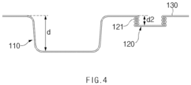
FIG. 2 is a perspective view illustrating a state when viewing the pouch-type battery case in another direction according to an embodiment of the present invention,FIG. 3 is a side view of the pouch-type battery case according to an embodiment of the present invention,FIG. 4 is a view illustrating a state in which the gas pocket part ofFIG. 3 is contracted, andFIG. 5 is a view illustrating a state in which the gas pocket part ofFIG. 3 is expanded. - For convenience of explanation, the
first case 101 illustrated inFIG. 1 is illustrated inFIGS. 2 to 5 . - The depth of the
gas pocket part 120 may vary by thewrinkle part 121 disposed on thegas pocket part 120. - As described above, the
wrinkle part 121 may have a bellows shape. In more detail, thewrinkle part 121 may include aconvex portion 122 that protrudes toward the outside of thegas pocket part 120 and aconcave portion 123 disposed alternately with theconvex portions 122 in the depth direction of thegas pocket part 120. - The
convex portion 122 may be formed to be convex toward the outside of thegas pocket part 120. Theconcave portion 123 may be provided concavely toward the inside of thegas pocket part 120. - A remaining thickness t1 of the
convex part 122 may be less than a remaining thickness t2 of theconcave part 123. In more detail, the remaining thickness t1 of the outermost part of theconvex part 122 may be less than the remaining thickness t2 of the innermost part of theconcave part 123. This may be a characteristic that appears when a negative pressure is applied to the outside of the circumferential portion of thegas pocket part 120 to mold thewrinkle part 121. This will be described in detail later with reference toFIG. 6 . - The
gas pocket part 120 may be molded at an initial depth d1. The initial depth d1 may be less than the depth d of thecup part 110. The initial depth d1 may refer to a depth after thewrinkle part 121 are formed in thegas pocket part 120. - The depth of the
gas pocket part 120 may vary by thewrinkle part 121. In more detail, when thewrinkle part 121 is contracted, the depth of thegas pocket part 120 may decrease. The contraction of thewrinkle part 121 may mean that a pitch p between the plurality ofconvex portions 122 decreases. On the other hand, when thewrinkle part 121 is expanded, the depth of thegas pocket part 120 may increase. The expansion of thewrinkle part 121 may mean that the pitch p between the plurality ofconvex portions 122 increases. - The depth of the
gas pocket part 120 may vary between a contracted depth d2 and an expanded depth d3. A range in which the depth of thegas pocket part 120 is variable may be within a range in which thewrinkle part 121 is not excessively deformed, and the function of thewrinkle part 121 is maintained. - As illustrated in
FIG. 4 , when thewrinkle part 121 is maximally contracted, thegas pocket part 120 may have the contracted depth d2. For example, when sealing thebattery case 100 in the negative pressure chamber, thewrinkle part 121 may be contracted so that thegas pocket part 120 has the contracted depth d2. - The contracted depth d2 may be less than the initial depth d1. In more detail, the contracted depth d2 may be 0.1 times or less than the initial depth d1. If the contracted depth d2 is greater than 0.1 times the initial depth d1, the
wrinkle part 121 may not be sufficiently deformed, and thegas pocket part 120 may be crushed when sealing thebattery case 100 in the negative pressure chamber. - As illustrated in
FIG. 5 , when thewrinkle part 121 are maximally expanded, thegas pocket part 120 may have the expanded depth d3. For example, during an activation process of charging and discharging theelectrode assembly 200 in the state in which thebattery case 100 is sealed, thewrinkle part 121 may be expanded due to the internal pressure of a gas generated by the activation process, so that thegas pocket part 120 have the expanded depth d3. - The expanded depth d3 may be greater than the contracted depth d1. The expanded depth d3 may be greater than the initial depth d1. In more detail, the expanded depth d3 may be 1.2 times to 1.3 times the initial depth d1. That is, the expanded depth d3 may be 12 times or more than the contracted depth d2. If the expanded depth d3 is less than 1.2 times the initial depth d1, there is a risk that the
wrinkle part 121 is not sufficiently deformed, and the gas is not sufficiently collected in thegas pocket part 120. On the other hand, if the expanded depth d3 is greater than 1.3 times the initial depth d1, cracks may occur due to excessive elongation of the circumferential portion of thegas pocket part 120 when molding thewrinkle part 121, or thegas pocket part 120 may be ruptured by the internal pressure of the collected gas. - In addition, the expanded depth d3 of the
gas pocket part 120 may be 0.7 times to 1.3 times the depth d of thecup part 110. If the expanded depth d3 is less than 0.7 times the depth d of thecup part 110, there is a risk that gas is not sufficiently collected in thegas pocket part 120. Conversely, if the expanded depth d3 is greater than 1.3 times the depth d of thecup part 110, a volume of thegas pocket part 120 may be unnecessarily large, and when molding thegas pocket part 120, thepouch sheet 137 may be excessively elongated to cause the cracks. - Thus, the
wrinkle part 121 may prevent thegas pocket part 120 from being crushed by the negative pressure and may increase an amount of gas collected by thegas pocket part 120 to improve stability in the activation process. -
FIG. 6 is a schematic view illustrating a device for molding a wrinkle part according to an embodiment of the present invention. -
FIG. 6 illustrates thegas pocket part 120 before the wrinkle part 121 (seeFIG. 3 ) is formed. Adevice 10 for molding thewrinkle part 121 on the circumferential portion of the gas pocket part 120 (hereinafter, referred to as a wrinkle molding device) may apply a negative pressure to the outside of the circumferential portion of thegas pocket part 120 to mold thewrinkle part 121. - In more detail, the
wrinkle molding device 10 may include a plurality ofsupport parts 11 that are in contact with an outer circumference of thegas pocket part 120 and disposed at a predetermined interval in the depth direction of thegas pocket part 120, and anegative pressure part 12 that applies a negative pressure to the outer circumference of thegas pocket part 120 through a gap g between the plurality ofsupport parts 11. - Each of the plurality of
support parts 11 may surround the outer circumference of thegas pocket part 120. The plurality ofsupport parts 11 may be in contact with the outer circumference of thegas pocket part 120 at predetermined intervals in the depth direction of thegas pocket part 120. When thenegative pressure part 12 applies a negative pressure to the outer circumference of thegas pocket part 120, each of the plurality ofsupport parts 11 may support the outer circumference of thegas pocket part 120. - In order to prevent the cracks from occurring in the
gas pocket part 120, an inner end of thesupport part 122 may be formed to be rounded. - The
negative pressure part 12 may apply the negative pressure to the outer circumference of thegas pocket part 120 through the gap g between the plurality ofsupport parts 11. For example, as illustrated inFIG. 6 , the plurality of gaps g may communicate with a negative pressure chamber, and thenegative pressure part 12 may apply the negative pressure to the negative pressure chamber. For example, thenegative pressure part 12 may include a negative pressure pump. - Thus, a portion of the circumferential portion of the
gas pocket part 120, which faces the gap g, may be elongated outward by the negative pressure. The portion of the circumferential portion of thegas pocket part 120, which faces the gap g, may be elongated and molded into the convex portion 122 (seeFIG. 3 ), and the portion that is in contact with thesupport part 11 may form theconcave portion 123. - As described above, since a portion of the circumferential portion of the
gas pocket part 120 is elongated outward and molded into theconvex portion 122, as illustrated inFIG. 3 , the remaining thickness t1 of theconvex portion 122 may be less than the remaining thickness t2 of theconcave portion 123. - The
wrinkle part 122 may be easily and quickly molded by thewrinkle molding device 10. -
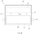
FIG. 7 is a flowchart illustrating a method for manufacturing a secondary battery according to another embodiment of the present invention, andFIGS. 8a to 8d are schematic views sequentially illustrating a method for manufacturing a secondary battery according to another embodiment of the present invention. - A method for manufacturing a secondary battery according to another embodiment of the present invention may be a method for manufacturing a secondary battery including the above-described
battery case 100. - The method for manufacturing the secondary battery may include a process (S10) of preparing a battery case 100 (hereinafter, referred to as a 'case preparation process'), a process (S20) of accommodating an
electrode assembly 200 and an electrolyte in a cup part 110 (hereinafter, referred to as an 'accommodation process'), a process (S30) of sealing abattery case 100 within a negative pressure chamber (hereinafter, referred to as a 'sealing process'), and a process (S40) of collecting a gas generated by charging and discharging of theelectrode assembly 200 into the gas pocket part 120 (hereinafter, referred to as a 'gas collection process'). - The case preparation process (S10) may be named a 'method for manufacturing a pouch-type battery case', and may itself constitute another embodiment of the present invention.
- In more detail, the case preparation process (S10) may include a process (S11) of molding the
cup part 110 and thegas pocket part 120 in the pouch sheet 137 (hereinafter, referred to as a 'first molding process'), and a process (S12) of molding awrinkle part 121, which is folded or unfolded depending on an internal pressure of thegas pocket part 120 so that a depth of thegas pocket part 120 is variable, on a circumferential portion of the gas pocket part 120 (hereinafter, referred to as a 'second molding process'). - In the first molding process (S11), each of the
cup part 110 and thegas pocket part 120 may be molded into thepouch sheet 137 to have an recessed shape. For example, thecup part 110 and thegas pocket part 120 may be drawn to be molded. Thegas pocket part 120 and thecup part 110 may be formed simultaneously or may be formed sequentially according to a preset order. - In the second molding process (S12), the wrinkle molding device 10 (see
FIG. 6 ) may apply a negative pressure to an outer circumference of thegas pocket part 120 to mold thewrinkle part 121. Since this has been explained previously, detailed contents will be omitted. - The
gas pocket part 120 in which thewrinkle part 121 is formed may have an initial depth d1. That is, in the case preparation process (S10), thegas pocket part 120 may be molded to the initial depth d1. - In the accommodation process (S20), a
folding part 140 may be folded in the state in which theelectrode assembly 200 is accommodated in thecup part 110, so that thefirst case 101 and thesecond case 102 face each other. - Thereafter, as illustrated in
FIG. 8a , some of portions at which aterrace 130 of thefirst case 101 and thesecond case 102 are in contact with each other may be thermally fused to form afirst sealing part 161. In a state in which thefolding part 140 is directed to face downward, thefirst sealing part 161 may be formed along both edges of thebattery case 100. In addition, an edge opposite to thefolding part 140 of each of thefirst case 101 and thesecond case 102 may be unsealed to form anopening 150. - Thereafter, an electrolyte may be injected through the
opening 150. The electrolyte may be introduced into thecup part 110 to impregnate theelectrode assembly 200. - In the sealing process (S30), as illustrated in
FIG. 8b , theopening 150 may be sealed to form asecond sealing part 162 connected to the previously formed first sealingpart 161. As a result, thebattery case 100 may be completely sealed. - The sealing process (S30) may be performed in a state in which the
battery case 100 is disposed in a negative pressure chamber (not shown) (e.g., a vacuum chamber). As a result, thebattery case 100 may be sealed in a state in which any gas or air remaining in thebattery case 100 is removed. - In the sealing process (S30), a depth of the
gas pocket part 120 may vary to a contracted depth d2 (seeFIG. 4 ) that is less than an initial depth d1. That is, as the negative pressure is applied within thegas pocket part 120 by the negative pressure chamber, thewrinkle part 121 may be contracted, and thus, the depth of thegas pocket part 120 may gradually decrease. As a result, thegas pocket part 120 may be prevented from being crushed. - As described above, the contracted depth d2 may be 0.1 times or less than the initial depth d1.
- After the
battery case 100 is sealed, theelectrode assembly 200 may be activated by charging and discharging theelectrode assembly 200 through anelectrode lead 210 protruding to the outside of thebattery case 100. - In the gas collection process (S40), as illustrated in
FIG. 8b , a gas generated by the activation of theelectrode assembly 200 may be collected in thegas pocket part 120. - In the gas collection process (S40), the depth of the
gas pocket part 120 may vary to an expanded depth d3 that is greater than the initial depth d1. That is, as the internal pressure of thegas pocket part 120 increases due to the collected gas, thewrinkle part 121 may be expanded, and the depth of thegas pocket part 120 may increase. As a result, thegas pocket part 120 may stably collect a sufficiently large amount of gas. - As described above, the expanded depth d3 may be 1.2 times to 1.3 times the initial depth d1.
- The method for manufacturing the secondary battery may further include a process (S50) of discharging the gas from the gas pocket part 120 (hereinafter, referred to as a 'degassing process'), and a process of additionally sealing the
battery case 100 and cutting the gas pocket part 120 (hereinafter, referred to as a 'cutting process'). - In the degassing process (S50), as illustrated in
FIG. 8c , at least one hole H may be formed by punching thegas pocket part 120 or the portion covering thegas pocket part 120, and the gas in thebattery case 100 may be discharged through the hole H. - The degassing process (S50) may be performed in a state in which the
battery case 100 is disposed in a negative pressure chamber (not shown) (e.g., a vacuum chamber). Thus, the gas in thebattery case 100, especially thegas pocket part 120, may be quickly discharged through the hole H. - In the cutting process (S60), as illustrated in
FIG. 8d , a portion between thecup part 110 and thegas pocket part 120 may be sealed to form a third sealing part 163. Both ends of the third sealing part 163 may be connected to thefirst sealing part 161. - Thereafter, the
battery case 100 may be cut along a virtual cutting line CL disposed on the third sealing part 163 or outside the third sealing part 163. As a result, a portion of thebattery case 100 including thegas pocket part 120 may be removed. - The above-disclosed subject matter is to be considered illustrative, and not restrictive, and the appended claims are intended to cover all such modifications, enhancements, and other embodiments, which fall within the true spirit and scope of the present invention.
- Thus, the embodiment of the present invention is to be considered illustrative, and not restrictive, and the technical spirit of the present invention is not limited to the foregoing embodiment.
- Therefore, the scope of the present invention is defined not by the detailed description of the invention but by the appended claims, and all differences within the scope will be construed as being included in the present invention.
-
10: Wrinkle molding device 11: Support part 12: Negative pressure part 100: Pouch-type battery case 101: First case 102: Second case 110: Cup part 120: Gas pocket part 121: Wrinkle part 122: Convex portion 123: Concave portion 130: Terrace 140: Folding part 200: Electrode assembly
Claims (11)
- A pouch-type battery case comprising:a cup part having a recessed shape; anda gas pocket part disposed at one side of the cup part and having a recessed shape,wherein a wrinkle part, which is folded or unfolded depending on an internal pressure of the gas pocket part so that a depth of the gas pocket part varies, is formed on a circumferential portion of the gas pocket part,wherein the wrinkle part comprises:a convex portion protruding toward the outside of the gas pocket part; anda concave portion which is alternately disposed with the convex portion in a depth direction of the gas pocket part,wherein a remaining thickness of the convex portion is less than a remaining thickness of the concave portion.
- The pouch-type battery case of claim 1, wherein a depth of the gas pocket part varies between a contracted depth and an expanded depth that is greater than the contracted depth, and
wherein the expanded depth is 0.7 times to 1.3 times a depth of the cup part. - The pouch-type battery case of claim 1, wherein a depth of the gas pocket part varies between a contracted depth and an expanded depth that is greater than the contracted depth, and
wherein the expanded depth is 12 times or more than the contracted depth. - A method for manufacturing a pouch-type battery case, the method comprising:molding a cup part and a gas pocket part in a pouch sheet; andmolding a wrinkle part, which is folded or unfolded depending on an internal pressure of the gas pocket part so that a depth of the gas pocket part varies, on a circumferential portion of the gas pocket part,wherein the wrinkle part comprises:a convex portion protruding toward the outside of the gas pocket part; anda concave portion which is alternately disposed with the convex portion in a depth direction of the gas pocket part,wherein a remaining thickness of the convex portion is less than a remaining thickness of the concave portion.
- The method of claim 4, wherein the gas pocket part, on which the wrinkle part is molded, has an initial depth, and
the depth of the gas pocket part varies between a contracted depth, which is less than the initial depth, and an expanded depth, which is greater than the initial depth. - The method of claim 5, wherein the contracted depth is 0.1 times or less than the initial depth.
- The method of claim 5, wherein the expanded depth is 1.2 times to 1.3 times the initial depth.
- The method of claim 4, wherein a device for molding the wrinkle part comprises:a plurality of support parts that are in contact with an outer circumference of the gas pocket part and disposed at predetermined intervals in a depth direction of the gas pocket part; anda negative pressure part configured to apply a negative pressure to the outer circumference of the gas pocket part through gaps between the plurality of support parts.
- A method for manufacturing a secondary battery, the method comprising:preparing a pouch-type battery case;accommodating an electrode assembly and an electrolyte in a cup part of the pouch-type battery case;sealing the pouch-type battery case within a negative pressure chamber; andcollecting a gas generated by charging and discharging of the electrode assembly into a gas pocket part of the pouch-type battery case,wherein the preparing of the pouch-type battery case comprises:molding the cup part and the gas pocket part in a pouch sheet; andmolding a wrinkle part, which is folded or unfolded depending on an internal pressure of the gas pocket part so that a depth of the gas pocket part varies, on a circumferential portion of the gas pocket part,wherein the wrinkle part comprises:a convex portion protruding toward the outside of the gas pocket part; anda concave portion which is alternately disposed with the convex portion in a depth direction of the gas pocket part,wherein a remaining thickness of the convex portion is less than a remaining thickness of the concave portion.
- The method of claim 9, wherein, in the preparing of the pouch-type battery case, the gas pocket part is molded to an initial depth, and
in the sealing of the pouch-type battery case, the depth of the gas pocket part varies to a contracted depth less than the initial depth. - The method of claim 10, wherein, in the collecting of the gas into the gas pocket part, the depth of the gas pocket part varies to an expanded depth greater than the initial depth.
Applications Claiming Priority (2)
| Application Number | Priority Date | Filing Date | Title |
|---|---|---|---|
| KR1020220108708A KR20240030103A (en) | 2022-08-29 | 2022-08-29 | Pouch type battery case and manufacturing method of the same, and manufacturing method of the secondary battery |
| PCT/KR2023/012803 WO2024049169A1 (en) | 2022-08-29 | 2023-08-29 | Pouch-type battery case, manufacturing method therefor, and secondary battery manufacturing method |
Publications (2)
| Publication Number | Publication Date |
|---|---|
| EP4583264A1 true EP4583264A1 (en) | 2025-07-09 |
| EP4583264A4 EP4583264A4 (en) | 2025-12-24 |
Family
ID=90098227
Family Applications (1)
| Application Number | Title | Priority Date | Filing Date |
|---|---|---|---|
| EP23860845.9A Pending EP4583264A4 (en) | 2022-08-29 | 2023-08-29 | POUCH-STYLE BATTERY HOUSING, MANUFACTURING METHOD FOR IT AND SECONDARY BATTERY MANUFACTURING METHOD |
Country Status (5)
| Country | Link |
|---|---|
| EP (1) | EP4583264A4 (en) |
| JP (1) | JP7831811B2 (en) |
| KR (1) | KR20240030103A (en) |
| CN (1) | CN119731844A (en) |
| WO (1) | WO2024049169A1 (en) |
Families Citing this family (1)
| Publication number | Priority date | Publication date | Assignee | Title |
|---|---|---|---|---|
| KR102900342B1 (en) * | 2023-12-15 | 2025-12-15 | 주식회사 엘지에너지솔루션 | Secondary battery |
Family Cites Families (12)
| Publication number | Priority date | Publication date | Assignee | Title |
|---|---|---|---|---|
| KR20150030861A (en) * | 2013-09-13 | 2015-03-23 | 주식회사 엘지화학 | Pouched type case, battery cell and manufacturing method of battery cell |
| KR102097084B1 (en) * | 2016-09-05 | 2020-04-03 | 주식회사 엘지화학 | Pouch type secondary battery and battery module including the same |
| KR20180091324A (en) * | 2017-02-06 | 2018-08-16 | 에이치엘그린파워 주식회사 | Battery cell and Secondary battery assembly comprising the same |
| JP6984463B2 (en) | 2018-02-07 | 2021-12-22 | Tdk株式会社 | Exterior for secondary battery and secondary battery |
| KR102699032B1 (en) * | 2018-12-05 | 2024-08-27 | 에스케이온 주식회사 | Pouch film and secondary comprising the same |
| KR102953606B1 (en) * | 2019-07-30 | 2026-04-15 | 주식회사 엘지에너지솔루션 | Secondary battery having reduced manufacturing cost and manufacturing method thereof |
| KR102773520B1 (en) | 2019-10-31 | 2025-02-27 | 에스케이온 주식회사 | Pouch Type Secondary Battery And Production Method Thereof |
| KR102743588B1 (en) * | 2019-11-06 | 2024-12-17 | 주식회사 엘지에너지솔루션 | Method for Preparing Pouch-type Battery Case Formed with Venting Guide Portion and Pouch-type Battery Case Manufactured by the Same |
| JP2021180072A (en) | 2020-05-11 | 2021-11-18 | 株式会社スリーダム | Laminated cell, battery module, and manufacturing method of laminated cell |
| CN213988964U (en) * | 2020-09-23 | 2021-08-17 | 双登集团股份有限公司 | Battery with breathable film bag |
| US12057592B2 (en) | 2020-09-25 | 2024-08-06 | Google Llc | Battery expansion control system |
| TWI788769B (en) | 2021-01-27 | 2023-01-01 | 大陸商河南烯力新材料科技有限公司 | Thermal conductive structure and electronic device |
-
2022
- 2022-08-29 KR KR1020220108708A patent/KR20240030103A/en active Pending
-
2023
- 2023-08-29 WO PCT/KR2023/012803 patent/WO2024049169A1/en not_active Ceased
- 2023-08-29 JP JP2025512012A patent/JP7831811B2/en active Active
- 2023-08-29 EP EP23860845.9A patent/EP4583264A4/en active Pending
- 2023-08-29 CN CN202380060811.8A patent/CN119731844A/en active Pending
Also Published As
| Publication number | Publication date |
|---|---|
| JP2025527758A (en) | 2025-08-22 |
| KR20240030103A (en) | 2024-03-07 |
| JP7831811B2 (en) | 2026-03-17 |
| WO2024049169A1 (en) | 2024-03-07 |
| EP4583264A4 (en) | 2025-12-24 |
| CN119731844A (en) | 2025-03-28 |
Similar Documents
| Publication | Publication Date | Title |
|---|---|---|
| US12243975B2 (en) | Method for manufacturing secondary battery and pouch for secondary battery | |
| US12057545B2 (en) | Pouch exterior material for secondary battery, pouch type secondary battery using the same, and method of manufacturing the same | |
| US20040234848A1 (en) | Pouch-type lithium secondary battery and fabrication method thereof | |
| KR101440096B1 (en) | Pouch for battery, and pouch type battery including the same | |
| US11362383B2 (en) | Secondary battery | |
| EP4148846A1 (en) | Battery cell having protective member | |
| KR20230057957A (en) | Secondary battery, manufacturing method of the secondary battery and degas apparatus used in the same | |
| CN119731844A (en) | Pouch-type battery case, method for manufacturing the same, and method for manufacturing secondary battery | |
| KR20070109080A (en) | Pouch Type Lithium Secondary Battery | |
| EP4290675B1 (en) | Battery cell and method of manufacturing the same | |
| KR102954862B1 (en) | Jelly roll type electrode assembly, battery cell including the same, and cylindrical battery | |
| CN120266325A (en) | Secondary battery | |
| EP4131589B1 (en) | Secondary battery manufacturing method | |
| EP4517945A1 (en) | Pouch-type battery case, pouch-type secondary battery comprising same, method for manufacturing pouch-type battery case, and molding jig for manufacturing pouch-type battery case | |
| US20250300279A1 (en) | Pouch-Type Battery Case and Pouch-Type Secondary Battery Including the Same, Method for Pouch-Type Battery Case, and Forming Jig for Manufacturing Pouch-Type Battery Case | |
| EP4579830A1 (en) | Method for manufacturing secondary battery | |
| US20260100458A1 (en) | Cap assembly, secondary battery including same, and method for manufacturing secondary battery | |
| EP4621947A1 (en) | Sealing device and pouch type secondary battery sealed thereby | |
| KR20040107041A (en) | Battery | |
| US20260081325A1 (en) | Battery and method of manufacturing same | |
| KR20260059534A (en) | Jelly roll type electrode assembly, battery cell including the same, and cylindrical battery | |
| WO2024137692A1 (en) | Battery cell | |
| KR20240162683A (en) | Battery cell comprising protection film and manufacutring method of battercy cell comprising protection film |
Legal Events
| Date | Code | Title | Description |
|---|---|---|---|
| STAA | Information on the status of an ep patent application or granted ep patent |
Free format text: STATUS: THE INTERNATIONAL PUBLICATION HAS BEEN MADE |
|
| PUAI | Public reference made under article 153(3) epc to a published international application that has entered the european phase |
Free format text: ORIGINAL CODE: 0009012 |
|
| STAA | Information on the status of an ep patent application or granted ep patent |
Free format text: STATUS: REQUEST FOR EXAMINATION WAS MADE |
|
| 17P | Request for examination filed |
Effective date: 20250217 |
|
| AK | Designated contracting states |
Kind code of ref document: A1 Designated state(s): AL AT BE BG CH CY CZ DE DK EE ES FI FR GB GR HR HU IE IS IT LI LT LU LV MC ME MK MT NL NO PL PT RO RS SE SI SK SM TR |
|
| DAV | Request for validation of the european patent (deleted) | ||
| DAX | Request for extension of the european patent (deleted) | ||
| A4 | Supplementary search report drawn up and despatched |
Effective date: 20251124 |
|
| RIC1 | Information provided on ipc code assigned before grant |
Ipc: H01M 50/105 20210101AFI20251118BHEP Ipc: B29C 51/10 20060101ALI20251118BHEP Ipc: B29C 51/30 20060101ALI20251118BHEP Ipc: H01M 10/04 20060101ALI20251118BHEP Ipc: H01M 50/30 20210101ALI20251118BHEP Ipc: H01M 10/42 20060101ALI20251118BHEP |