EP4583249A1 - Battery module and battery pack - Google Patents
Battery module and battery pack Download PDFInfo
- Publication number
- EP4583249A1 EP4583249A1 EP24219077.5A EP24219077A EP4583249A1 EP 4583249 A1 EP4583249 A1 EP 4583249A1 EP 24219077 A EP24219077 A EP 24219077A EP 4583249 A1 EP4583249 A1 EP 4583249A1
- Authority
- EP
- European Patent Office
- Prior art keywords
- pressure
- relief
- liquid
- heat
- cooling
- Prior art date
- Legal status (The legal status is an assumption and is not a legal conclusion. Google has not performed a legal analysis and makes no representation as to the accuracy of the status listed.)
- Pending
Links
Images

Classifications
-
- H—ELECTRICITY
- H01—ELECTRIC ELEMENTS
- H01M—PROCESSES OR MEANS, e.g. BATTERIES, FOR THE DIRECT CONVERSION OF CHEMICAL ENERGY INTO ELECTRICAL ENERGY
- H01M50/00—Constructional details or processes of manufacture of the non-active parts of electrochemical cells other than fuel cells, e.g. hybrid cells
- H01M50/30—Arrangements for facilitating escape of gases
- H01M50/317—Re-sealable arrangements
- H01M50/325—Re-sealable arrangements comprising deformable valve members, e.g. elastic or flexible valve members
-
- H—ELECTRICITY
- H01—ELECTRIC ELEMENTS
- H01M—PROCESSES OR MEANS, e.g. BATTERIES, FOR THE DIRECT CONVERSION OF CHEMICAL ENERGY INTO ELECTRICAL ENERGY
- H01M10/00—Secondary cells; Manufacture thereof
- H01M10/60—Heating or cooling; Temperature control
- H01M10/61—Types of temperature control
- H01M10/613—Cooling or keeping cold
-
- H—ELECTRICITY
- H01—ELECTRIC ELEMENTS
- H01M—PROCESSES OR MEANS, e.g. BATTERIES, FOR THE DIRECT CONVERSION OF CHEMICAL ENERGY INTO ELECTRICAL ENERGY
- H01M10/00—Secondary cells; Manufacture thereof
- H01M10/60—Heating or cooling; Temperature control
- H01M10/64—Heating or cooling; Temperature control characterised by the shape of the cells
- H01M10/647—Prismatic or flat cells, e.g. pouch cells
-
- H—ELECTRICITY
- H01—ELECTRIC ELEMENTS
- H01M—PROCESSES OR MEANS, e.g. BATTERIES, FOR THE DIRECT CONVERSION OF CHEMICAL ENERGY INTO ELECTRICAL ENERGY
- H01M10/00—Secondary cells; Manufacture thereof
- H01M10/60—Heating or cooling; Temperature control
- H01M10/65—Means for temperature control structurally associated with the cells
- H01M10/655—Solid structures for heat exchange or heat conduction
- H01M10/6554—Rods or plates
-
- H—ELECTRICITY
- H01—ELECTRIC ELEMENTS
- H01M—PROCESSES OR MEANS, e.g. BATTERIES, FOR THE DIRECT CONVERSION OF CHEMICAL ENERGY INTO ELECTRICAL ENERGY
- H01M10/00—Secondary cells; Manufacture thereof
- H01M10/60—Heating or cooling; Temperature control
- H01M10/65—Means for temperature control structurally associated with the cells
- H01M10/655—Solid structures for heat exchange or heat conduction
- H01M10/6556—Solid parts with flow channel passages or pipes for heat exchange
-
- H—ELECTRICITY
- H01—ELECTRIC ELEMENTS
- H01M—PROCESSES OR MEANS, e.g. BATTERIES, FOR THE DIRECT CONVERSION OF CHEMICAL ENERGY INTO ELECTRICAL ENERGY
- H01M10/00—Secondary cells; Manufacture thereof
- H01M10/60—Heating or cooling; Temperature control
- H01M10/65—Means for temperature control structurally associated with the cells
- H01M10/655—Solid structures for heat exchange or heat conduction
- H01M10/6556—Solid parts with flow channel passages or pipes for heat exchange
- H01M10/6557—Solid parts with flow channel passages or pipes for heat exchange arranged between the cells
-
- H—ELECTRICITY
- H01—ELECTRIC ELEMENTS
- H01M—PROCESSES OR MEANS, e.g. BATTERIES, FOR THE DIRECT CONVERSION OF CHEMICAL ENERGY INTO ELECTRICAL ENERGY
- H01M10/00—Secondary cells; Manufacture thereof
- H01M10/60—Heating or cooling; Temperature control
- H01M10/65—Means for temperature control structurally associated with the cells
- H01M10/656—Means for temperature control structurally associated with the cells characterised by the type of heat-exchange fluid
- H01M10/6567—Liquids
-
- H—ELECTRICITY
- H01—ELECTRIC ELEMENTS
- H01M—PROCESSES OR MEANS, e.g. BATTERIES, FOR THE DIRECT CONVERSION OF CHEMICAL ENERGY INTO ELECTRICAL ENERGY
- H01M10/00—Secondary cells; Manufacture thereof
- H01M10/60—Heating or cooling; Temperature control
- H01M10/65—Means for temperature control structurally associated with the cells
- H01M10/656—Means for temperature control structurally associated with the cells characterised by the type of heat-exchange fluid
- H01M10/6567—Liquids
- H01M10/6568—Liquids characterised by flow circuits, e.g. loops, located externally to the cells or cell casings
-
- H—ELECTRICITY
- H01—ELECTRIC ELEMENTS
- H01M—PROCESSES OR MEANS, e.g. BATTERIES, FOR THE DIRECT CONVERSION OF CHEMICAL ENERGY INTO ELECTRICAL ENERGY
- H01M50/00—Constructional details or processes of manufacture of the non-active parts of electrochemical cells other than fuel cells, e.g. hybrid cells
- H01M50/20—Mountings; Secondary casings or frames; Racks, modules or packs; Suspension devices; Shock absorbers; Transport or carrying devices; Holders
- H01M50/204—Racks, modules or packs for multiple batteries or multiple cells
- H01M50/207—Racks, modules or packs for multiple batteries or multiple cells characterised by their shape
- H01M50/209—Racks, modules or packs for multiple batteries or multiple cells characterised by their shape adapted for prismatic or rectangular cells
-
- H—ELECTRICITY
- H01—ELECTRIC ELEMENTS
- H01M—PROCESSES OR MEANS, e.g. BATTERIES, FOR THE DIRECT CONVERSION OF CHEMICAL ENERGY INTO ELECTRICAL ENERGY
- H01M50/00—Constructional details or processes of manufacture of the non-active parts of electrochemical cells other than fuel cells, e.g. hybrid cells
- H01M50/30—Arrangements for facilitating escape of gases
- H01M50/342—Non-re-sealable arrangements
- H01M50/3425—Non-re-sealable arrangements in the form of rupturable membranes or weakened parts, e.g. pierced with the aid of a sharp member
-
- H—ELECTRICITY
- H01—ELECTRIC ELEMENTS
- H01M—PROCESSES OR MEANS, e.g. BATTERIES, FOR THE DIRECT CONVERSION OF CHEMICAL ENERGY INTO ELECTRICAL ENERGY
- H01M50/00—Constructional details or processes of manufacture of the non-active parts of electrochemical cells other than fuel cells, e.g. hybrid cells
- H01M50/30—Arrangements for facilitating escape of gases
- H01M50/35—Gas exhaust passages comprising elongated, tortuous or labyrinth-shaped exhaust passages
- H01M50/358—External gas exhaust passages located on the battery cover or case
-
- H—ELECTRICITY
- H01—ELECTRIC ELEMENTS
- H01M—PROCESSES OR MEANS, e.g. BATTERIES, FOR THE DIRECT CONVERSION OF CHEMICAL ENERGY INTO ELECTRICAL ENERGY
- H01M50/00—Constructional details or processes of manufacture of the non-active parts of electrochemical cells other than fuel cells, e.g. hybrid cells
- H01M50/30—Arrangements for facilitating escape of gases
- H01M50/35—Gas exhaust passages comprising elongated, tortuous or labyrinth-shaped exhaust passages
- H01M50/367—Internal gas exhaust passages forming part of the battery cover or case; Double cover vent systems
-
- Y—GENERAL TAGGING OF NEW TECHNOLOGICAL DEVELOPMENTS; GENERAL TAGGING OF CROSS-SECTIONAL TECHNOLOGIES SPANNING OVER SEVERAL SECTIONS OF THE IPC; TECHNICAL SUBJECTS COVERED BY FORMER USPC CROSS-REFERENCE ART COLLECTIONS [XRACs] AND DIGESTS
- Y02—TECHNOLOGIES OR APPLICATIONS FOR MITIGATION OR ADAPTATION AGAINST CLIMATE CHANGE
- Y02E—REDUCTION OF GREENHOUSE GAS [GHG] EMISSIONS, RELATED TO ENERGY GENERATION, TRANSMISSION OR DISTRIBUTION
- Y02E60/00—Enabling technologies; Technologies with a potential or indirect contribution to GHG emissions mitigation
- Y02E60/10—Energy storage using batteries
Definitions
- liquid-cooling plates are usually provided on side surfaces of the cell, and special pressure-relief channels are arranged in a spraying direction of an explosion-proof valve of the cell. These pressure-relief channels are usually arranged in an independently arranged pressure-relief plate.
- the thickness dimension of the supporting side wall 131 may also be adjusted and selected within a dimension range of 5 millimeters to 10 millimeters according to the capacitance of the (passenger car) cell. That is, when the capacitance of the cell is small, a smaller dimension within the range may be selected, for example, a dimension of 5 millimeters may be selected, while when the capacitance of the cell is large, a larger dimension within the range may be selected, for example, a dimension of 10 millimeters may be selected.
- the smoke-exhaust and pressure-relief portion 12 is provided with two pressure-relief channels 13 and a supporting partition wall 15 arranged between the two pressure-relief channels 13.
- the supporting partition wall 15 herein is a solid structure.
- the liquid-cooling partition 11 is arranged between the two pressure-relief channels 13, and the liquid-cooling partition 11 is fixed to the supporting partition wall 15, thereby effectively ensuring the overall structural strength of the heat-dissipation and pressure-relief component 1, and facilitating producing same.
- a thickness dimension H2 of the supporting partition wall 15 is between 3 millimeters and 6 millimeters. If the thickness dimension H2 of the supporting partition wall 15 is less than 3 millimeters, the thickness dimension H2 of the supporting partition wall 15 is excessively thin.
- the released high-temperature gas or the sprayed high-temperature substance from the cell easily causes thermal shock to the supporting partition wall 15, and damages to the pressure-relief channel 13, resulting in that the high-temperature gas, even the high-temperature substance, flows into the adjacent pressure-relief channel 13, thereby causing a risk of thermal spreading in the battery module 100.
- the thickness dimension H2 of the supporting partition wall 15 is excessively thick, which not only increases the weight of the heat-dissipation and pressure-relief component 1, but also increases the overall weight of the battery module 100 and the battery pack, which is not conductive to the light-weight design of the battery.
- the unit flow area of the pressure-relief channel 13 is also compressed, which easily leads to a risk of blockage caused by the accumulation of high-temperature substances sprayed by the cell 2 in the pressure-relief channel 13, resulting in the failure of the heat dissipation and pressure relief functions of the pressure-relief channel 13, leading to a more serious risk of thermal runaway and thermal spread in the battery module 100.
- the thickness dimension H2 of the supporting partition wall 15 is between 3 millimeters and 6 millimeters, which can not only ensure the structural strength of the supporting partition wall 15 and the heat-dissipation pressure relief member 1, reduce or even avoid the risk of damage caused by thermal shock, but also avoid the risk of blockage caused by the accumulation of high-temperature substances in the pressure-relief channel 13, thereby ensuring the effectiveness of the heat dissipation and pressure relief functions of the pressure-relief channel 13, and well ensuring the stability and the safety of the battery module 100 and the battery pack in use.
- the thickness dimension H2 of the supporting partition wall 15 is 5 millimeters.
- the liquid-cooling partition 11 is provided with a heat exchange plate 111 and a plurality of heat exchange channels 112.
- the heat exchange plate 111 is a side surface of the liquid-cooling partition 11 having the largest area and exchanging heat with the cell 2.
- a direction in which the heat exchange plate 111 perpendicular to the smoke-exhaust and pressure-relief portion 12 is a width direction W of the heat exchange plate 111, and the plurality of heat exchange channels 112 are arranged along the width direction W of the heat exchange plate 111.
- the heat exchange medium flows inside the heat exchange channel 112.
- the heat exchange medium herein may be water or cooling liquid.
- the large battery surface of the cell 2 is in abutting contact with the heat-exchanging plate 111 of the liquid-cooling partition 11, so that a large amount of heat released by the cell 2 is transferred to the heat-exchanging medium through the heat-exchanging plate 111 of the liquid-cooling partition 11.
- the large amount of heat can be quickly discharged out of the heat-dissipation and pressure-relief component 1, thereby achieving the purpose of effective heat dissipation.
- one side of the liquid-cooling partition 11 close to the smoke-exhaust and pressure-relief portion 12 is provided with a first connection portion 161.
- the first connection portion 161 extends along the extending direction of the heat exchange channel 112, and the length dimension of the first connection portion 161 extending towards the width direction W of the heat exchange plate 111 is not limited herein.
- the liquid-cooling partition 11 is connected to the smoke-exhaust and pressure-relief portion 12 through the first connection portion 161.
- the connection mentioned here may be a fixed connection, such as welding connection, integrated molding, or a detachable connection, such as plugging, clamping, etc.
- connection strength between the liquid-cooling partition 11 and the smoke-exhaust and pressure-relief portion 12 can be improved, thereby avoiding the risk of fracture at the junction between the liquid-cooling partition 11 and the smoke-exhaust and pressure-relief portion 12 caused by the concentrated stress generated by the vertical connection between the liquid-cooling partition 11 and the smoke-exhaust and pressure-relief portion 12, and improving the overall structural strength of the heat-dissipation and pressure-relief component 1.
- the heat-dissipation and pressure-relief component 1 further includes a liquid-cooling connector 17 provided with a liquid-cooling inner cavity 171, and an external pipe element 18 provided on the liquid-cooling connector 17.
- the liquid-cooling connector 17 is detachably connected to the liquid-cooling partition 11, and the heat exchange channel 112 is in communication with the external pipe element 18 through the liquid-cooling inner cavity 171.
- the liquid-cooling partition 11 is further provided with a second connection portion 162 arranged in the extending direction of the heat exchange channel 112, allowing the liquid-cooling connector 17 to be more easily and conveniently plugged into the liquid-cooling partition 11.
- a second connection portion 162 arranged in the extending direction of the heat exchange channel 112, allowing the liquid-cooling connector 17 to be more easily and conveniently plugged into the liquid-cooling partition 11.
- one of the inner cavity wall of the liquid-cooling inner cavity 171 and the liquid-cooling partition 11 can be provided with a snap protrusion, while the other one of the inner cavity wall of the liquid-cooling inner cavity 171 and the liquid-cooling partition 11 can be provided with a snap groove, and the snap protrusion is snap-fitted in the snap groove.
- the heat exchange medium flows from the liquid-cooling connector 17 into the liquid-cooling inner cavity 171, and then flows into the heat exchange channel 112.
- the liquid-cooling connector 17 is further provided with a flow guide plate 172 arranged in the liquid-cooling inner cavity 171, so as to enable adjacent heat exchange channels 112 to be communicated end to end, and the plurality of heat exchange channels 112 can be formed into a serpentine pipe by means of the flow guide plate 172, and the heat exchange medium can flow from bottom to top along the width direction W of the heat exchange plate 111.
- the heat exchange medium will be able to flow from top to bottom along the width direction W of the heat exchange plate 111.
- the flow path of the heat exchange medium is greatly increased, and the heat exchange time between the heat exchange medium and the cell is prolonged, thus, the utilization rate of the heat exchange medium is effectively improved.
- the amount of the exhaust ports 14 is multiple.
- the multiple exhaust ports 14 are evenly arranged along the extending direction of the pressure-relief channel 13. Therefore, when multiple cells 2 are configured, the exhaust ports 14 are arranged in one-to-one correspondence with the explosion-proof valves 21 of the cells 2.
- the high-temperature gas, the smoke and the high-temperature substances can be released into the pressure-relief channel 13, and then can be discharged to the outside of the heat-dissipation and pressure-relief component 1 of the battery module 100 through the guidance of the pressure-relief channel 13.
- the battery module 100 may include multiple heat-dissipation and pressure-relief components 1 and multiple cells 2 mounted on the heat-dissipation and pressure-relief components 1.
- the plurality of exhaust ports 14 are correspondingly arranged on the smoke exhaust pressure portion 12, and the exhaust ports 14 are arranged in one-to-one correspondence with the explosion-proof valves of the cells 2.
- the plurality of heat-dissipation and pressure-relief components 1 are arranged in sequence, and the pressure-relief channels 13 of two adjacent heat-dissipation and pressure-relief components 1 are in communication with each other.
- the cells 2 assembled on two adjacent heat-dissipation and pressure-relief components 1 may be in abutting contact with each other, and a heat-insulating plate may be further provided between the cells 2 assembled on the two adjacent heat-dissipation and pressure-relief components 1 arranged side by side.
- the external pipe elements 18 of two adjacent heat-dissipation and pressure-relief components 1 may be connected together through connecting pipes.
- the connecting pipe members here may be self deformed, so that the connecting pipe member can be adjusted according to the spacing between the liquid-cooling connectors 17 of the two adjacent heat-dissipation and pressure-relief components 1.
- the connecting pipe here can also be selected as a pipe provided with an adjustment structure.
- the adjustment structure is configured to perform telescopic adjustment in an axial direction of the connecting pipe, and can also be adjusted according to the spacing between the liquid-cooling connectors 17 of the two adjacent heat-dissipation and pressure-relief components 1.
- the present disclosure further provides a battery pack 1000, which includes the battery module 100 provided by the above-mentioned embodiments of the present disclosure.
Landscapes
- Chemical & Material Sciences (AREA)
- Chemical Kinetics & Catalysis (AREA)
- Electrochemistry (AREA)
- General Chemical & Material Sciences (AREA)
- Engineering & Computer Science (AREA)
- Manufacturing & Machinery (AREA)
- Battery Mounting, Suspending (AREA)
- Secondary Cells (AREA)
Abstract
A battery module (100) and a battery pack (1000) employing the battery module are provided. The battery module includes a cell (2) and a heat-dissipation and pressure-relief component (1). The heat-dissipation and pressure-relief component (1) is provided with a liquid-cooling partition (11) and a smoke-exhaust and pressure-relief portion (12). The smoke-exhaust and pressure-relief portion (12) is provided with a pressure-relief channel (13) and an exhaust port (14) communicating with the pressure-relief channel (13). The liquid-cooling partition (11) is arranged at one side of the pressure-relief channel (13) and is vertically connected to the smoke-exhaust and pressure-relief portion (12). The thickness dimensions H1 of two supporting side walls (131) of the pressure-relief channel (13) are both between 5 millimeter to 10 millimeters. An explosion-proof valve (21) of the cell (2) is arranged corresponding to the exhaust port (14), and the cell (2) exchanges heat with the liquid-cooling partition (11).
Description
- The present disclosure relates to the technology field of batteries, and in particular, to a battery module and a battery pack.
- In related technologies of battery packs, in order to dissipate heat from a cell and relieve pressure caused by thermal runaway occurred in the cell, liquid-cooling plates are usually provided on side surfaces of the cell, and special pressure-relief channels are arranged in a spraying direction of an explosion-proof valve of the cell. These pressure-relief channels are usually arranged in an independently arranged pressure-relief plate.
- In this way, during the installation of the cell, an exhaust port of the pressure-relief plate and the explosion-proof valve of the cell need to be installed in alignment. At the same time, the liquid-cooling plate needs to be adjusted according to the position adjustment of the cell, which will result in a long time required for installation and adjustment of the cell, leading to low efficiency. While when the liquid-cooling plate and the pressure-relief plate are integrally formed, due to the pressure-relief channels provided inside the pressure-relief plate, and liquid-cooling channels provided inside the liquid-cooling plate, a junction between the pressure-relief plate and the liquid-cooling plate only has the wall thickness of the liquid-cooling channel or the wall thickness of the pressure-relief channel. While gas and substances released by the cell under a thermal runaway state all have a large amount of heat, which results in a risk of damage to the junction between the pressure-relief plate and the liquid-cooling plate when the junction is subjected to thermal shock from the high-temperature gas and high-temperature substances.
- In a first aspect, the present disclosure provides a battery module which includes a cell and a heat-dissipation and pressure-relief component. The heat-dissipation and pressure-relief component includes a liquid-cooling partition and a smoke-exhaust and pressure-relief portion. The smoke-exhaust and pressure-relief portion is provided with a pressure-relief channel and an exhaust port in communication with the pressure-relief channel. The liquid-cooling partition is arranged at one side of the pressure-relief channel, and the liquid-cooling partition is vertically connected to the smoke-exhaust and pressure-relief portion. The thickness dimensions of the two supporting side walls of the pressure-relief channel are both between 5 millimeters and 10 millimeters. The exhaust port is arranged corresponding to an explosion-proof valve of the cell. The cell exchanges heat with the liquid-cooling partition.
- In a second aspect, the present disclosure further discloses a battery pack including the battery module provided by the present disclosure.
- In the battery module and the battery pack provided by the present disclosure, the liquid-cooling partition is provided at one side of the pressure-relief channel, and the thickness dimension of the supporting side wall of the pressure-relief channel is between 5 millimeters and 10 millimeters, so that the overall structure of the heat-dissipation and pressure-relief component is made relatively firm and stable, thereby avoiding the risk that significant concentrated stress at the junction between the liquid-cooling partition and the smoke-discharging and pressure-relief portion, which could easily damage the location when subjected to thermal shock from high-temperature gas and high-temperature substances. This ensures the effectiveness and stability of the heat dissipation and pressure relief function of the pressure-relief channel, and also avoids the risk of blockage of the pressure-relief channel caused by the accumulation of the high-temperature substances in the pressure-relief channel.
-
-
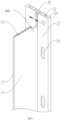
FIG. 1 is a schematic diagram of an overall structure of heat-dissipation and pressure-relief component of a battery module according to some embodiments of the present disclosure. -
FIG. 2 is a partial structural schematic diagram of the heat-dissipation and pressure-relief component according to some embodiments of the present disclosure. -
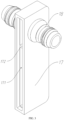
FIG. 3 is an assembly diagram of a liquid-cooling connector and an external pipe element according to some embodiments of the present disclosure. -
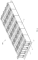
FIG. 4 is a structural schematic diagram of a battery module according to some embodiments of the present disclosure. -
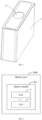
FIG. 5 is a structural schematic diagram of a cell according to some embodiments of the present disclosure. -
FIG. 6 is a schematic diagram of a battery pack according to some embodiments of the present disclosure. - Reference numerals in the drawings: 1000, battery pack; 100, battery module; 2, cell; 21, explosion-proof valve; 1, heat-dissipation and pressure-relief component; 11, liquid-cooling partition; 111, heat exchange plate; 112, heat exchange channel; 12, smoke-exhaust and pressure-relief portion; 13, pressure-relief channel; 131, supporting side wall; 14, exhaust port; 15, supporting partition wall; 161, first connection portion; 162, second connection portion; 17, liquid-cooling connector; 171, liquid-cooling inner cavity; 172, flow guide plate; 18, external pipe element.
- Specifically, as shown in
FIGS. 1 to 5 , the present disclosure discloses abattery module 100, which includes acell 2 and a heat-dissipation and pressure-relief component 1. Thecell 2 can be a square-type battery, a cylindrical-type battery, or a prismatic battery, and the largest side surface of thecell 2 is a large battery surface. The heat-dissipation and pressure-relief component 1 includes a liquid-cooling partition 11 and a smoke-exhaust and pressure-relief portion 12. The liquid-cooling partition 11 and the smoke-exhaust and pressure-relief portion 12 are integrally formed or separately arranged. The smoke-exhaust and pressure-relief portion 12 is provided with a pressure-relief channel 13 and anexhaust port 14 in communication with the pressure-relief channel 13. As shown inFIGs. 1 ,4 and5 , the shape and size of theexhaust port 14 are respectively adapted to the shape and size of an explosion-proof valve 21 of thecell 2. The explosion-proof valve 21 of thecell 2 is arranged corresponding to theexhaust port 14. Therefore, when thecell 2 is in a thermal runaway state, high-temperature gas, smoke, and high-temperature substances released by thecell 2 can enter the pressure-relief channel 13 through theexhaust port 14, and then flow and discharge in an orderly manner under the guidance of the pressure-relief channel 13, thereby preventing thebattery module 100 from experiencing secondary short circuits or arcing. - In some embodiments, the liquid-
cooling partition 11 is arranged at one side of the pressure-relief channel 13, and the liquid-cooling partition 11 is fixed to a supportingside wall 131 of the pressure-relief channel 13, which helps to ensure the overall structural strength of the heat-dissipation and pressure-relief component 1. The liquid-cooling partition 11 is vertically connected to the smoke-exhaust and pressure-relief portion 12. When thecell 2 is assembled on the heat-dissipation and pressure-relief component 1, the large battery surface of thecell 2 is attached to and in contact with the liquid-cooling partition 11, so as to ensure maximum efficiency of heat exchange between thecell 2 and the liquid-cooling partition 11, so that a large amount of heat released by thecell 2 in any one or a combination of two of normal charging and discharging states and thermal runaway states can be transferred to the liquid-cooling partition 11, achieving heat exchange between thecell 2 and the liquid-cooling partition 11, and finally quickly evacuated and eliminated through the liquid-cooling partition 11, so that the risk of thermal spreading in thebattery module 100 is avoided. - In some embodiments, the thickness dimensions H1 of two supporting
side walls 131 of the pressure-relief channel 13 are both between 5 millimeters and 10 millimeters. If the thickness dimension H1 of the supportingside wall 131 is less than 5 millimeters, the thickness dimension H1 of the supportingside wall 131 is excessively thin, when the thermal runaway occurs in thecell 2, the high-temperature gas released by thecell 2 or the high-temperature substances sprayed by thecell 2 can easily cause thermal shock to the supportingside wall 131, which can easily damage the pressure-relief channel 13, and cause the high-temperature gas and even the high-temperature substances to flow out of the damaged area, resulting in thermal spread in thebattery module 100. In addition, it also makes it difficult to form the supportingside wall 131 during the process of manufacturing the heat-dissipation and pressure-relief component 1, which increases the difficulty in manufacturing the heat-dissipation and pressure-relief component 1. At the same time, since the supportingside wall 131 also needs to bear the weight of at least onecell 2, if the supportingside wall 131 is excessively thin, it is easy to crush the supportingside wall 131, thereby destroying the structures of the pressure-relief channel 13 and the heat-dissipation and pressure-relief component 1, causing the pressure-relief channel 13 to lose its functions of directional discharge of smoke and high-temperature gases. While if the thickness dimension H1 of the supportingside wall 131 is greater than 10 millimeters, the thickness dimension H1 of the supportingside wall 131 is excessively thick, which not only increases the weight of the heat-dissipation and pressure-relief component 1, but also increases the overall weight of thebattery module 100 and the battery pack, which is not conductive to the light-weight design of the battery. At the same time, the unit flow area of the pressure-relief channel 13 is compressed, which easily leads to a risk of blockage caused by the accumulation of high-temperature substances sprayed by thecell 2 in the pressure-relief channel 13, resulting in the failure of heat dissipation and pressure relief functions of the pressure-relief channel 13, and leading to a more serious risk of thermal runaway and thermal spread of thebattery module 100. - The supporting
side wall 131 has a thickness between 5 millimeters and 10 millimeters, which can not only ensure the structural strength of the supportingside wall 131 and the heat-dissipation and pressure-relief component 1, reduce or even avoid the risk of damage caused by thermal shock, but also avoid the risk of blockage caused by the accumulation of the high-temperature substances in the pressure-relief channel 13, thereby ensuring the effectiveness of the heat dissipation and pressure relief functions of the pressure-relief channel 13, and well ensuring the stability and the safety of of thebattery module 100 and the battery pack in use. The thickness dimension H1 of the supportingside wall 131 is 6 millimeters, 7 millimeters or 8 millimeters. - It should be noted that, the thickness dimension of the supporting
side wall 131 may also be adjusted and selected within a dimension range of 5 millimeters to 10 millimeters according to the capacitance of the (passenger car) cell. That is, when the capacitance of the cell is small, a smaller dimension within the range may be selected, for example, a dimension of 5 millimeters may be selected, while when the capacitance of the cell is large, a larger dimension within the range may be selected, for example, a dimension of 10 millimeters may be selected. - In some embodiments, as shown in
FIGS. 1 and2 , the smoke-exhaust and pressure-relief portion 12 is provided with two pressure-relief channels 13 and a supportingpartition wall 15 arranged between the two pressure-relief channels 13. The supportingpartition wall 15 herein is a solid structure. The liquid-cooling partition 11 is arranged between the two pressure-relief channels 13, and the liquid-cooling partition 11 is fixed to the supportingpartition wall 15, thereby effectively ensuring the overall structural strength of the heat-dissipation and pressure-relief component 1, and facilitating producing same. - As shown in
FIG. 2 , a thickness dimension H2 of the supportingpartition wall 15 is between 3 millimeters and 6 millimeters. If the thickness dimension H2 of the supportingpartition wall 15 is less than 3 millimeters, the thickness dimension H2 of the supportingpartition wall 15 is excessively thin. When thermal runaway occurs in the cell, the released high-temperature gas or the sprayed high-temperature substance from the cell easily causes thermal shock to the supportingpartition wall 15, and damages to the pressure-relief channel 13, resulting in that the high-temperature gas, even the high-temperature substance, flows into the adjacent pressure-relief channel 13, thereby causing a risk of thermal spreading in thebattery module 100. In addition, it also make it difficult to form the supportingpartition wall 15 during the process of manufacturing the heat-dissipation and pressure-relief component 1, which increases the difficulty in manufacturing the heat-dissipation and pressure-relief component 1. - While if the thickness dimension H2 of the supporting
partition wall 15 is greater than 6 millimeters, the thickness dimension H2 of the supportingpartition wall 15 is excessively thick, which not only increases the weight of the heat-dissipation and pressure-relief component 1, but also increases the overall weight of thebattery module 100 and the battery pack, which is not conductive to the light-weight design of the battery. At the same time, the unit flow area of the pressure-relief channel 13 is also compressed, which easily leads to a risk of blockage caused by the accumulation of high-temperature substances sprayed by thecell 2 in the pressure-relief channel 13, resulting in the failure of the heat dissipation and pressure relief functions of the pressure-relief channel 13, leading to a more serious risk of thermal runaway and thermal spread in thebattery module 100. - The thickness dimension H2 of the supporting
partition wall 15 is between 3 millimeters and 6 millimeters, which can not only ensure the structural strength of the supportingpartition wall 15 and the heat-dissipation pressure relief member 1, reduce or even avoid the risk of damage caused by thermal shock, but also avoid the risk of blockage caused by the accumulation of high-temperature substances in the pressure-relief channel 13, thereby ensuring the effectiveness of the heat dissipation and pressure relief functions of the pressure-relief channel 13, and well ensuring the stability and the safety of thebattery module 100 and the battery pack in use. The thickness dimension H2 of the supportingpartition wall 15 is 5 millimeters. - In some embodiments, as shown in
FIG. 2 , the liquid-cooling partition 11 is provided with aheat exchange plate 111 and a plurality ofheat exchange channels 112. Theheat exchange plate 111 is a side surface of the liquid-cooling partition 11 having the largest area and exchanging heat with thecell 2. A direction in which theheat exchange plate 111 perpendicular to the smoke-exhaust and pressure-relief portion 12 is a width direction W of theheat exchange plate 111, and the plurality ofheat exchange channels 112 are arranged along the width direction W of theheat exchange plate 111. - In this way, the heat exchange medium flows inside the
heat exchange channel 112. The heat exchange medium herein may be water or cooling liquid. The large battery surface of thecell 2 is in abutting contact with the heat-exchangingplate 111 of the liquid-coolingpartition 11, so that a large amount of heat released by thecell 2 is transferred to the heat-exchanging medium through the heat-exchangingplate 111 of the liquid-coolingpartition 11. With the flow of the heat-exchanging medium, the large amount of heat can be quickly discharged out of the heat-dissipation and pressure-relief component 1, thereby achieving the purpose of effective heat dissipation. - In some embodiments, as shown in
FIGS. 1 and2 , one side of the liquid-coolingpartition 11 close to the smoke-exhaust and pressure-relief portion 12 is provided with afirst connection portion 161. Thefirst connection portion 161 extends along the extending direction of theheat exchange channel 112, and the length dimension of thefirst connection portion 161 extending towards the width direction W of theheat exchange plate 111 is not limited herein. The liquid-coolingpartition 11 is connected to the smoke-exhaust and pressure-relief portion 12 through thefirst connection portion 161. The connection mentioned here may be a fixed connection, such as welding connection, integrated molding, or a detachable connection, such as plugging, clamping, etc. - In this way, under the action of the first connection portion 16, the connection strength between the liquid-cooling
partition 11 and the smoke-exhaust and pressure-relief portion 12 can be improved, thereby avoiding the risk of fracture at the junction between the liquid-coolingpartition 11 and the smoke-exhaust and pressure-relief portion 12 caused by the concentrated stress generated by the vertical connection between the liquid-coolingpartition 11 and the smoke-exhaust and pressure-relief portion 12, and improving the overall structural strength of the heat-dissipation and pressure-relief component 1. - In order to convey an external cooling medium into the
heat exchange channel 112 of the liquid-coolingpartition 11, as shown inFIGS. 1 and3 , the heat-dissipation and pressure-relief component 1 further includes a liquid-coolingconnector 17 provided with a liquid-coolinginner cavity 171, and anexternal pipe element 18 provided on the liquid-coolingconnector 17. The liquid-coolingconnector 17 is detachably connected to the liquid-coolingpartition 11, and theheat exchange channel 112 is in communication with theexternal pipe element 18 through the liquid-coolinginner cavity 171. - Specifically, the liquid-cooling
partition 11 is further provided with asecond connection portion 162 arranged in the extending direction of theheat exchange channel 112, allowing the liquid-coolingconnector 17 to be more easily and conveniently plugged into the liquid-coolingpartition 11. In order to strengthen the connection between the liquid-coolingconnector 17 and the liquid-coolingpartition 11, to make the liquid-coolingconnector 17 be not easily separated from the liquid-coolingpartition 11, one of the inner cavity wall of the liquid-coolinginner cavity 171 and the liquid-coolingpartition 11 can be provided with a snap protrusion, while the other one of the inner cavity wall of the liquid-coolinginner cavity 171 and the liquid-coolingpartition 11 can be provided with a snap groove, and the snap protrusion is snap-fitted in the snap groove. - In this way, the heat exchange medium flows from the liquid-cooling
connector 17 into the liquid-coolinginner cavity 171, and then flows into theheat exchange channel 112. In some embodiments, the liquid-coolingconnector 17 is further provided with aflow guide plate 172 arranged in the liquid-coolinginner cavity 171, so as to enable adjacentheat exchange channels 112 to be communicated end to end, and the plurality ofheat exchange channels 112 can be formed into a serpentine pipe by means of theflow guide plate 172, and the heat exchange medium can flow from bottom to top along the width direction W of theheat exchange plate 111. Alternatively, the heat exchange medium will be able to flow from top to bottom along the width direction W of theheat exchange plate 111. Thus, the flow path of the heat exchange medium is greatly increased, and the heat exchange time between the heat exchange medium and the cell is prolonged, thus, the utilization rate of the heat exchange medium is effectively improved. - AIn some embodiments, as shown in
FIGS. 1 and2 , the amount of theexhaust ports 14 is multiple. Themultiple exhaust ports 14 are evenly arranged along the extending direction of the pressure-relief channel 13. Therefore, whenmultiple cells 2 are configured, theexhaust ports 14 are arranged in one-to-one correspondence with the explosion-proof valves 21 of thecells 2. When thermal runaway occurs in any one of thecells 2, the high-temperature gas, the smoke and the high-temperature substances can be released into the pressure-relief channel 13, and then can be discharged to the outside of the heat-dissipation and pressure-relief component 1 of thebattery module 100 through the guidance of the pressure-relief channel 13. - In some embodiments, as shown in
FIG. 4 , thebattery module 100 may include multiple heat-dissipation and pressure-relief components 1 andmultiple cells 2 mounted on the heat-dissipation and pressure-relief components 1. The plurality ofexhaust ports 14 are correspondingly arranged on the smokeexhaust pressure portion 12, and theexhaust ports 14 are arranged in one-to-one correspondence with the explosion-proof valves of thecells 2. The plurality of heat-dissipation and pressure-relief components 1 are arranged in sequence, and the pressure-relief channels 13 of two adjacent heat-dissipation and pressure-relief components 1 are in communication with each other. - The sequential arrangement herein should be understood as that the plurality of heat-dissipation and pressure-relief components 1 are sequentially arranged along a direction perpendicular to the heat-
exchange plate 111 of the liquid-coolingpartition 11, so that the heat-exchange plates 111 of the plurality of heat-dissipation and pressure-relief components 1 are parallel to each other. When the plurality of heat-dissipation and pressure-relief components 1 are arranged in sequence, thecells 2 assembled on two adjacent heat-dissipation and pressure-relief components 1 may be in abutting contact with each other, and a heat-insulating plate may be further provided between thecells 2 assembled on the two adjacent heat-dissipation and pressure-relief components 1 arranged side by side. - Specifically, the
external pipe elements 18 of two adjacent heat-dissipation and pressure-relief components 1 may be connected together through connecting pipes. The connecting pipe members here may be self deformed, so that the connecting pipe member can be adjusted according to the spacing between the liquid-coolingconnectors 17 of the two adjacent heat-dissipation and pressure-relief components 1. The connecting pipe here can also be selected as a pipe provided with an adjustment structure. The adjustment structure is configured to perform telescopic adjustment in an axial direction of the connecting pipe, and can also be adjusted according to the spacing between the liquid-coolingconnectors 17 of the two adjacent heat-dissipation and pressure-relief components 1. - As shown in
FIG. 6 , the present disclosure further provides abattery pack 1000, which includes thebattery module 100 provided by the above-mentioned embodiments of the present disclosure.
Claims (15)
- A battery module (100), comprising:a cell (2); anda heat-dissipation and pressure-relief component (1) comprising a liquid-cooling partition (11) and a smoke-exhaust and pressure-relief portion (12); wherein the smoke-exhaust and pressure-relief portion (12) is provided with a pressure-relief channel (13) and an exhaust port (14) in communication with the pressure-relief channel (13); the liquid-cooling partition (11) is arranged at one side of the pressure-relief channel (13), and the liquid-cooling partition (11) is vertically connected to the smoke-exhaust and pressure-relief portion (12); thickness dimensions of two supporting side walls (131) of the pressure-relief channel (13) are both between 5 millimeters and 10 millimeters; and the exhaust port (14) is arranged corresponding to an explosion-proof valve (21) of the cell (2); and the cell (2) exchanges heat with the liquid-cooling partition (11).
- The battery module (100) according to claim 1, wherein the smoke-exhaust and pressure-relief portion (12) is provided with two pressure-relief channels (13) and a supporting partition wall (15) arranged between the two pressure-relief channels (13); a thickness dimension of the supporting partition wall (15) is between 3 millimeters and 6 millimeters; the liquid-cooling partition (11) is arranged between the two pressure-relief channels (13), and is fixed to the supporting partition wall (15).
- The battery module (100) according to claim 1 or 2, wherein the liquid-cooling partition (11) is provided with a heat exchange plate (111) and a plurality of heat exchange channels (112); wherein a direction in which the heat exchange plate (111) perpendicular to the smoke-exhaust and pressure-relief portion (12) is a width direction of the heat exchange plate (111), and the plurality of heat exchange channels (112) are arranged along the width direction of the heat exchange plate (111).
- The battery module (100) according to claim 3, wherein one side of the liquid-cooling partition (11) close to the smoke-exhaust and pressure-relief portion (12) is provided with a first connection portion (161); wherein the liquid-cooling partition (11) is connected to the smoke-exhaust and pressure-relief portion (12) through the first connection portion (161).
- The battery module (100) according to claim 3, wherein the heat-dissipation and pressure-relief component (1) further comprises a liquid-cooling connector (17) provided with a liquid-cooling inner cavity (171), and an external pipe element (18) provided on the liquid-cooling connector (17); wherein the liquid-cooling connector (17) is detachably connected to the liquid-cooling partition (11), and the heat exchange channel (112) is in communication with the external pipe element (18) through the liquid-cooling inner cavity (171).
- The battery module (100) according to claim 5, wherein the liquid-cooling partition (11) is further provided with a second connection portion (162) arranged in an extending direction of the heat exchange channel (112); wherein the liquid-cooling connector (17) is plugged into the liquid-cooling partition (11) through the second connection portion (162).
- The battery module (100) according to claim 5, wherein the liquid-cooling connector (17) is further provided with a flow guide plate (172) arranged in the liquid-cooling inner cavity (171); wherein the plurality of heat exchange channels (112) are formed into a serpentine pipe by means of the flow guide plate (172).
- The battery module (100) according to claim 1 or 2, wherein the amount of the exhaust port (14) is multiple, and multiple exhaust ports (14) are evenly arranged along an extending direction of the pressure-relief channel (13).
- The battery module (100) according to claim 1 or 2, wherein the amount of the heat-dissipation and pressure-relief component (1) is multiple, and the amount of the cell (2) is multiple; wherein the multiple cells (2) are mounted on the multiple heat-dissipation and pressure-relief components (1); the multiple heat-dissipation and pressure-relief components (1) are arranged in sequence, and the pressure-relief channels (13) of two adjacent heat-dissipation and pressure-relief components (1) are in communication with each other.
- The battery module (100) according to claim 9, wherein the cells (2) assembled on two adjacent heat-dissipation and pressure-relief components (1) are in abutting contact with each other; a heat-insulating plate is provided between the cells (2) assembled on the two adjacent heat-dissipation and pressure-relief components (1) arranged side by side.
- The battery module (100) according to claim 5, wherein the amount of the heat-dissipation and pressure-relief component (1) is multiple, and the amount of the cell (2) is multiple; wherein the multiple cells (2) are mounted on the multiple heat-dissipation and pressure-relief components (1); the multiple heat-dissipation and pressure-relief components (1) are arranged in sequence, and the pressure-relief channels (13) of two adjacent heat-dissipation and pressure-relief components (1) are in communication with each other; the external pipe elements (18) of two adjacent heat-dissipation and pressure-relief components (1) are connected together through connecting pipes.
- The battery module (100) according to any one of claims 1 to 11, wherein the shape and size of the exhaust port (14) are respectively adapted to the shape and size of the explosion-proof valve (21) of the cell (2).
- The battery module (100) according to any one of claims 1 to 11, wherein the liquid-cooling partition (11) is fixed to one of the two supporting side walls (131) of the pressure-relief channel (13).
- The battery module (100) according to claim 2, wherein the liquid-cooling partition (11) is fixed to the supporting partition wall (15).
- A battery pack (1000), comprising the battery module according to any one of claims 1 to 14.
Applications Claiming Priority (1)
| Application Number | Priority Date | Filing Date | Title |
|---|---|---|---|
| CN202420028791.8U CN222126876U (en) | 2024-01-04 | 2024-01-04 | Battery module and battery pack |
Publications (1)
| Publication Number | Publication Date |
|---|---|
| EP4583249A1 true EP4583249A1 (en) | 2025-07-09 |
Family
ID=93681532
Family Applications (1)
| Application Number | Title | Priority Date | Filing Date |
|---|---|---|---|
| EP24219077.5A Pending EP4583249A1 (en) | 2024-01-04 | 2024-12-11 | Battery module and battery pack |
Country Status (5)
| Country | Link |
|---|---|
| US (1) | US20250226523A1 (en) |
| EP (1) | EP4583249A1 (en) |
| KR (1) | KR20250107111A (en) |
| CN (1) | CN222126876U (en) |
| WO (1) | WO2025145516A1 (en) |
Citations (3)
| Publication number | Priority date | Publication date | Assignee | Title |
|---|---|---|---|---|
| CN219476783U (en) * | 2022-11-29 | 2023-08-04 | 华人运通(山东)科技有限公司 | Liquid cooling plate, liquid cooling system and battery pack |
| CN116666828A (en) * | 2023-06-29 | 2023-08-29 | 惠州亿纬锂能股份有限公司 | Liquid cooling assembly, battery module and battery pack |
| CN220155700U (en) * | 2023-06-30 | 2023-12-08 | 惠州亿纬锂能股份有限公司 | Heat dissipation pressure relief device, battery module and battery pack |
Family Cites Families (5)
| Publication number | Priority date | Publication date | Assignee | Title |
|---|---|---|---|---|
| DE102010018040A1 (en) * | 2010-04-23 | 2011-11-03 | Akasol Engineering Gmbh | Cooling module manufacturing method for lithium-ion battery, involves forming set of groove cooling passages at pressed metal part, and extending cooling passages from input regions to output regions |
| CN211265671U (en) * | 2019-12-30 | 2020-08-14 | 合肥国轩高科动力能源有限公司 | Liquid cooling box of lithium battery module |
| CN218070021U (en) * | 2022-09-09 | 2022-12-16 | 江苏正力新能电池技术有限公司 | Battery module, battery package, power consumption device and equipment for manufacturing battery module |
| CN115579563B (en) * | 2022-09-09 | 2024-09-10 | 江苏正力新能电池技术股份有限公司 | A battery module, a battery pack, an electric device and equipment for manufacturing a battery module |
| CN220830080U (en) * | 2023-09-12 | 2024-04-23 | 惠州亿纬锂能股份有限公司 | Pressure release structure, battery module and battery pack |
-
2024
- 2024-01-04 CN CN202420028791.8U patent/CN222126876U/en active Active
- 2024-05-17 WO PCT/CN2024/094081 patent/WO2025145516A1/en active Pending
- 2024-12-11 EP EP24219077.5A patent/EP4583249A1/en active Pending
- 2024-12-18 US US18/985,068 patent/US20250226523A1/en active Pending
- 2024-12-23 KR KR1020240194781A patent/KR20250107111A/en active Pending
Patent Citations (3)
| Publication number | Priority date | Publication date | Assignee | Title |
|---|---|---|---|---|
| CN219476783U (en) * | 2022-11-29 | 2023-08-04 | 华人运通(山东)科技有限公司 | Liquid cooling plate, liquid cooling system and battery pack |
| CN116666828A (en) * | 2023-06-29 | 2023-08-29 | 惠州亿纬锂能股份有限公司 | Liquid cooling assembly, battery module and battery pack |
| CN220155700U (en) * | 2023-06-30 | 2023-12-08 | 惠州亿纬锂能股份有限公司 | Heat dissipation pressure relief device, battery module and battery pack |
Also Published As
| Publication number | Publication date |
|---|---|
| KR20250107111A (en) | 2025-07-11 |
| US20250226523A1 (en) | 2025-07-10 |
| WO2025145516A1 (en) | 2025-07-10 |
| CN222126876U (en) | 2024-12-06 |
Similar Documents
| Publication | Publication Date | Title |
|---|---|---|
| JP7618672B2 (en) | Battery module, battery pack, and device using secondary battery | |
| EP4243173B1 (en) | Battery cell module and battery system | |
| JP5422596B2 (en) | Secondary battery module and secondary battery pack | |
| CN219457896U (en) | Cell module | |
| KR20200044580A (en) | Large module of battery | |
| CN118198623A (en) | Batteries and electrical devices | |
| EP4513643A1 (en) | Battery module and battery pack | |
| AU2024201727A1 (en) | Battery box, battery pack and energy storage container | |
| CN220544136U (en) | Battery pack trays, battery packs and vehicles | |
| EP4583249A1 (en) | Battery module and battery pack | |
| US20250309466A1 (en) | Pressure relief structure for double-layer battery and battery pack | |
| CN222940005U (en) | Battery pack cooling structure, battery pack and vehicle | |
| WO2025208714A1 (en) | Housing, cell liquid-cooling case, and battery pack | |
| CN218586160U (en) | Energy storage warehouse and energy storage system | |
| CN111431043A (en) | Switch cabinet for arcing pressure relief | |
| CN116706375A (en) | Mounting structure, battery pack and vehicle | |
| CN221613995U (en) | Battery pack and electrical equipment | |
| CN222995503U (en) | Battery pack | |
| CN222463051U (en) | Battery box and power battery | |
| US20250309407A1 (en) | Box, cell liquid cooling box and battery pack | |
| CN222338392U (en) | New energy automobile's battery package assembly and new energy automobile | |
| CN224138185U (en) | Thermal management components, battery packs and battery stacks | |
| CN117013176B (en) | Battery cell rack | |
| CN222654247U (en) | Battery pack and electric equipment | |
| CN221126106U (en) | Column-shaped battery cell end part cooling device and battery pack |
Legal Events
| Date | Code | Title | Description |
|---|---|---|---|
| PUAI | Public reference made under article 153(3) epc to a published international application that has entered the european phase |
Free format text: ORIGINAL CODE: 0009012 |
|
| STAA | Information on the status of an ep patent application or granted ep patent |
Free format text: STATUS: REQUEST FOR EXAMINATION WAS MADE |
|
| 17P | Request for examination filed |
Effective date: 20241211 |
|
| AK | Designated contracting states |
Kind code of ref document: A1 Designated state(s): AL AT BE BG CH CY CZ DE DK EE ES FI FR GB GR HR HU IE IS IT LI LT LU LV MC ME MK MT NL NO PL PT RO RS SE SI SK SM TR |
|
| STAA | Information on the status of an ep patent application or granted ep patent |
Free format text: STATUS: EXAMINATION IS IN PROGRESS |
|
| 17Q | First examination report despatched |
Effective date: 20260226 |