EP4583219A2 - Rechargeable battery module - Google Patents
Rechargeable battery module Download PDFInfo
- Publication number
- EP4583219A2 EP4583219A2 EP24219803.4A EP24219803A EP4583219A2 EP 4583219 A2 EP4583219 A2 EP 4583219A2 EP 24219803 A EP24219803 A EP 24219803A EP 4583219 A2 EP4583219 A2 EP 4583219A2
- Authority
- EP
- European Patent Office
- Prior art keywords
- catching
- contact plate
- elastic
- rechargeable battery
- battery module
- Prior art date
- Legal status (The legal status is an assumption and is not a legal conclusion. Google has not performed a legal analysis and makes no representation as to the accuracy of the status listed.)
- Pending
Links
Images


Classifications
-
- H—ELECTRICITY
- H01—ELECTRIC ELEMENTS
- H01M—PROCESSES OR MEANS, e.g. BATTERIES, FOR THE DIRECT CONVERSION OF CHEMICAL ENERGY INTO ELECTRICAL ENERGY
- H01M10/00—Secondary cells; Manufacture thereof
- H01M10/42—Methods or arrangements for servicing or maintenance of secondary cells or secondary half-cells
- H01M10/48—Accumulators combined with arrangements for measuring, testing or indicating the condition of cells, e.g. the level or density of the electrolyte
- H01M10/486—Accumulators combined with arrangements for measuring, testing or indicating the condition of cells, e.g. the level or density of the electrolyte for measuring temperature
-
- H—ELECTRICITY
- H01—ELECTRIC ELEMENTS
- H01M—PROCESSES OR MEANS, e.g. BATTERIES, FOR THE DIRECT CONVERSION OF CHEMICAL ENERGY INTO ELECTRICAL ENERGY
- H01M10/00—Secondary cells; Manufacture thereof
- H01M10/04—Construction or manufacture in general
- H01M10/0481—Compression means other than compression means for stacks of electrodes and separators
-
- H—ELECTRICITY
- H01—ELECTRIC ELEMENTS
- H01M—PROCESSES OR MEANS, e.g. BATTERIES, FOR THE DIRECT CONVERSION OF CHEMICAL ENERGY INTO ELECTRICAL ENERGY
- H01M10/00—Secondary cells; Manufacture thereof
- H01M10/42—Methods or arrangements for servicing or maintenance of secondary cells or secondary half-cells
- H01M10/425—Structural combination with electronic components, e.g. electronic circuits integrated to the outside of the casing
-
- H—ELECTRICITY
- H01—ELECTRIC ELEMENTS
- H01M—PROCESSES OR MEANS, e.g. BATTERIES, FOR THE DIRECT CONVERSION OF CHEMICAL ENERGY INTO ELECTRICAL ENERGY
- H01M10/00—Secondary cells; Manufacture thereof
- H01M10/42—Methods or arrangements for servicing or maintenance of secondary cells or secondary half-cells
- H01M10/48—Accumulators combined with arrangements for measuring, testing or indicating the condition of cells, e.g. the level or density of the electrolyte
- H01M10/482—Accumulators combined with arrangements for measuring, testing or indicating the condition of cells, e.g. the level or density of the electrolyte for several batteries or cells simultaneously or sequentially
-
- H—ELECTRICITY
- H01—ELECTRIC ELEMENTS
- H01M—PROCESSES OR MEANS, e.g. BATTERIES, FOR THE DIRECT CONVERSION OF CHEMICAL ENERGY INTO ELECTRICAL ENERGY
- H01M50/00—Constructional details or processes of manufacture of the non-active parts of electrochemical cells other than fuel cells, e.g. hybrid cells
- H01M50/20—Mountings; Secondary casings or frames; Racks, modules or packs; Suspension devices; Shock absorbers; Transport or carrying devices; Holders
- H01M50/204—Racks, modules or packs for multiple batteries or multiple cells
- H01M50/207—Racks, modules or packs for multiple batteries or multiple cells characterised by their shape
- H01M50/209—Racks, modules or packs for multiple batteries or multiple cells characterised by their shape adapted for prismatic or rectangular cells
-
- H—ELECTRICITY
- H01—ELECTRIC ELEMENTS
- H01M—PROCESSES OR MEANS, e.g. BATTERIES, FOR THE DIRECT CONVERSION OF CHEMICAL ENERGY INTO ELECTRICAL ENERGY
- H01M50/00—Constructional details or processes of manufacture of the non-active parts of electrochemical cells other than fuel cells, e.g. hybrid cells
- H01M50/20—Mountings; Secondary casings or frames; Racks, modules or packs; Suspension devices; Shock absorbers; Transport or carrying devices; Holders
- H01M50/284—Mountings; Secondary casings or frames; Racks, modules or packs; Suspension devices; Shock absorbers; Transport or carrying devices; Holders with incorporated circuit boards, e.g. printed circuit boards [PCB]
-
- H—ELECTRICITY
- H01—ELECTRIC ELEMENTS
- H01M—PROCESSES OR MEANS, e.g. BATTERIES, FOR THE DIRECT CONVERSION OF CHEMICAL ENERGY INTO ELECTRICAL ENERGY
- H01M50/00—Constructional details or processes of manufacture of the non-active parts of electrochemical cells other than fuel cells, e.g. hybrid cells
- H01M50/50—Current conducting connections for cells or batteries
-
- H—ELECTRICITY
- H01—ELECTRIC ELEMENTS
- H01M—PROCESSES OR MEANS, e.g. BATTERIES, FOR THE DIRECT CONVERSION OF CHEMICAL ENERGY INTO ELECTRICAL ENERGY
- H01M50/00—Constructional details or processes of manufacture of the non-active parts of electrochemical cells other than fuel cells, e.g. hybrid cells
- H01M50/50—Current conducting connections for cells or batteries
- H01M50/502—Interconnectors for connecting terminals of adjacent batteries; Interconnectors for connecting cells outside a battery casing
-
- H—ELECTRICITY
- H01—ELECTRIC ELEMENTS
- H01M—PROCESSES OR MEANS, e.g. BATTERIES, FOR THE DIRECT CONVERSION OF CHEMICAL ENERGY INTO ELECTRICAL ENERGY
- H01M50/00—Constructional details or processes of manufacture of the non-active parts of electrochemical cells other than fuel cells, e.g. hybrid cells
- H01M50/50—Current conducting connections for cells or batteries
- H01M50/502—Interconnectors for connecting terminals of adjacent batteries; Interconnectors for connecting cells outside a battery casing
- H01M50/507—Interconnectors for connecting terminals of adjacent batteries; Interconnectors for connecting cells outside a battery casing comprising an arrangement of two or more busbars within a container structure, e.g. busbar modules
-
- H—ELECTRICITY
- H01—ELECTRIC ELEMENTS
- H01M—PROCESSES OR MEANS, e.g. BATTERIES, FOR THE DIRECT CONVERSION OF CHEMICAL ENERGY INTO ELECTRICAL ENERGY
- H01M50/00—Constructional details or processes of manufacture of the non-active parts of electrochemical cells other than fuel cells, e.g. hybrid cells
- H01M50/50—Current conducting connections for cells or batteries
- H01M50/502—Interconnectors for connecting terminals of adjacent batteries; Interconnectors for connecting cells outside a battery casing
- H01M50/514—Methods for interconnecting adjacent batteries or cells
- H01M50/517—Methods for interconnecting adjacent batteries or cells by fixing means, e.g. screws, rivets or bolts
-
- H—ELECTRICITY
- H01—ELECTRIC ELEMENTS
- H01M—PROCESSES OR MEANS, e.g. BATTERIES, FOR THE DIRECT CONVERSION OF CHEMICAL ENERGY INTO ELECTRICAL ENERGY
- H01M50/00—Constructional details or processes of manufacture of the non-active parts of electrochemical cells other than fuel cells, e.g. hybrid cells
- H01M50/50—Current conducting connections for cells or batteries
- H01M50/502—Interconnectors for connecting terminals of adjacent batteries; Interconnectors for connecting cells outside a battery casing
- H01M50/519—Interconnectors for connecting terminals of adjacent batteries; Interconnectors for connecting cells outside a battery casing comprising printed circuit boards [PCB]
-
- H—ELECTRICITY
- H01—ELECTRIC ELEMENTS
- H01M—PROCESSES OR MEANS, e.g. BATTERIES, FOR THE DIRECT CONVERSION OF CHEMICAL ENERGY INTO ELECTRICAL ENERGY
- H01M50/00—Constructional details or processes of manufacture of the non-active parts of electrochemical cells other than fuel cells, e.g. hybrid cells
- H01M50/50—Current conducting connections for cells or batteries
- H01M50/569—Constructional details of current conducting connections for detecting conditions inside cells or batteries, e.g. details of voltage sensing terminals
-
- H—ELECTRICITY
- H05—ELECTRIC TECHNIQUES NOT OTHERWISE PROVIDED FOR
- H05K—PRINTED CIRCUITS; CASINGS OR CONSTRUCTIONAL DETAILS OF ELECTRIC APPARATUS; MANUFACTURE OF ASSEMBLAGES OF ELECTRICAL COMPONENTS
- H05K1/00—Printed circuits
- H05K1/02—Details
- H05K1/14—Structural association of two or more printed circuits
- H05K1/147—Structural association of two or more printed circuits at least one of the printed circuits being bent or folded, e.g. by using a flexible printed circuit
-
- Y—GENERAL TAGGING OF NEW TECHNOLOGICAL DEVELOPMENTS; GENERAL TAGGING OF CROSS-SECTIONAL TECHNOLOGIES SPANNING OVER SEVERAL SECTIONS OF THE IPC; TECHNICAL SUBJECTS COVERED BY FORMER USPC CROSS-REFERENCE ART COLLECTIONS [XRACs] AND DIGESTS
- Y02—TECHNOLOGIES OR APPLICATIONS FOR MITIGATION OR ADAPTATION AGAINST CLIMATE CHANGE
- Y02E—REDUCTION OF GREENHOUSE GAS [GHG] EMISSIONS, RELATED TO ENERGY GENERATION, TRANSMISSION OR DISTRIBUTION
- Y02E60/00—Enabling technologies; Technologies with a potential or indirect contribution to GHG emissions mitigation
- Y02E60/10—Energy storage using batteries
Definitions
- the present invention relates to a rechargeable battery module.
- a rechargeable battery is a battery that is designed to be repeatedly charged and discharged, different from a primary battery.
- a small-capacity rechargeable battery may be used in a portable, small electronic device, such as a mobile phone, a laptop computer, and a camcorder.
- a large-capacity and high-density rechargeable battery may be used for a power source or energy storage for driving a motor of a hybrid vehicle and an electric vehicle.
- the rechargeable battery may be used as a rechargeable battery module including a plurality of battery cells connected together in series and/or in parallel to be able to, as an example, drive a motor of a hybrid vehicle, which requires a relatively high energy density.
- a rechargeable battery module comprises a temperature sensor that is connected between a flexible printed circuit (FPC) and a battery cell.
- the invention provides a rechargeable battery module capable of reducing or eliminating defects that may be caused by welding because welding is not used to connect a tab to which a temperature sensor mounted on a flexible printed circuit (FPC) to a battery cell.
- the invention also provides a rechargeable battery module capable of reducing or eliminating certain costs, such as a process cost and quality management cost, because welding is not used.
- the cell contact portion may include: a contact plate portion in contact with the one of the battery cells; a first catching portion in the contact plate portion at a side away from the sensor connection portion and on the busbar holder; and a second catching portion spaced apart from the first catching portion and in the contact plate portion nearer to the sensor connection portion than the first catching portion is and coupled under the busbar holder.
- the first catching portion may be an appendix of the contact plate portion and / or may be formed as a protrusion or tongue.
- the second catching portion may be an appendix of the contact plate portion and / or may be formed as a protrusion or tongue.
- the elastic member may include: a first elastic portion coupled at a first through hole in the first catching portion and configured to apply an elastic force to the first catching portion; and a second elastic portion coupled at a second through hole in the second catching portion and configured to apply an elastic force to the second catching portion.
- the first elastic portion may apply the elastic force in response to an elastic deformation of the first elastic portion.
- the second elastic portion may apply the elastic force in response to an elastic deformation of the second elastic portion.
- the elastic member may further include a connection portion interconnecting the first elastic portion and the second elastic portion in a crossing direction.
- the first and second elastic portions may form the sides of the H-shape of the elastic member and the connection portion may for the middle bar of the H-shape of the elastic member.
- the busbar holder may include: a seating groove having an open top corresponding to the first catching portion; and a hook having an open bottom corresponding to the second catching portion.
- the first catching portion may extend in a horizontal direction in the seating groove, and the second catching portion may extend in an inclined direction and may be restrained under the hook.
- the second catching portion may be configured to: in a first state, form a first angle by being bent from the contact plate portion; and in a second state when caught by the hook, form a second angle that is greater than the first angle.
- a second elastic portion may have a curved shape convex toward the contact plate portion in a free state, that may be a free state of the second elastic portion, and may be configured to provide an elastic force toward the contact plate portion in a state in which it is coupled to the second catching portion restrained by the hook.
- the second elastic portion may apply the elastic force in response to an elastic deformation of the second elastic portion out of its free state and into the state in which it is coupled to the second catching portion restrained by the hook.
- the elastic force provided to the contact plate portion through the second catching portion by the second elastic portion may be highest at a center of the contact plate portion and may decrease toward both ends.
- the first catching portion In a free state, the first catching portion may be configured to form an angle that is greater than the first angle by being bent from the contact plate portion.
- the free state may be a free state of the first catching portion.
- a first elastic portion of the elastic member may have a curved shape convex toward the contact plate portion and may be configured to provide an elastic force toward the contact plate portion in a state in which it is coupled to the first catching portion in the seating groove.
- the free state may be a free state of the first elastic portion.
- the first elastic portion may apply the elastic force in response to an elastic deformation of the first elastic portion out of its free state and into the state in which it is coupled to the first catching portion in the seating groove.
- the elastic force provided to the contact plate portion through the first catching portion by the first elastic portion may be highest at a center of the contact plate portion and may decrease toward both ends.
- the cell contact portion may include: a contact plate portion in contact with the one of the battery cells; a pair of first catching portions respectively extending from opposite sides of the contact plate portion in a width direction at an area of the contact plate portion away from the sensor connection portion, the first catching portions being on the busbar holder; and a pair of second catching portions respectively extending from the opposite sides of the contact plate portion in the width direction at another area of the contact plate portion nearer to the sensor connection portion, the second catching portions being coupled under the busbar holder.
- the elastic member may include: a first elastic portion coupled to each of first through holes respectively in the pair of first catching portions and configured to apply an elastic force to the first catching portion; and a second elastic portion coupled to each of second through holes respectively in the pair of second catching portions and configured to apply an elastic force to the second catching portion.
- the pair of first catching portions may form a first gap; and the pair of second catching portions may form a second gap that is greater than the first gap.
- a temperature sensing tab may be formed as a sensor connection portion, and a cell contact portion and a temperature sensor of the flexible printed circuit (FPC) is connected to the sensor connection portion, a temperature sensor may be connected between a flexible printed circuit (FPC) and a battery cell.
- welding may not be used and, instead, a cell contact portion in contact with the battery cell and elastically pressurizing the cell contact portion by an elastic member may be utilized to prevent defects that may be caused by welding.
- costs such as the process cost and quality management cost, may be eliminated.
- the respective portion In its free state the respective portion may be free from external forces seeking to deform the respective portion.
- the expression "at least one of a, b, or c" indicates only a, only b, only c, both a and b, both a and c, both b and c, all of a, b, and c, or variations thereof.
- the terms “use,” “using,” and “used” may be considered synonymous with the terms “utilize,” “utilizing,” and “utilized,” respectively.
- the terms “substantially,” “about,” and similar terms are used as terms of approximation and not as terms of degree, and are intended to account for the inherent variations in measured or calculated values that would be recognized by those of ordinary skill in the art.
- the elastic force provided to the cell contact portion 42 by the first catching portion 421, which receives the elastic force of the first elastic portion 51, may be highest at a center of the cell contact portion 42 (the center of FIG. 6 in the left-and-right direction) and may decrease toward both ends. This may be seen from the elastic force F of the second catching portion 422 by the second elastic portion 52 shown in, for example, FIG. 6 .
Landscapes
- Chemical & Material Sciences (AREA)
- Chemical Kinetics & Catalysis (AREA)
- Electrochemistry (AREA)
- General Chemical & Material Sciences (AREA)
- Engineering & Computer Science (AREA)
- Manufacturing & Machinery (AREA)
- Microelectronics & Electronic Packaging (AREA)
- Battery Mounting, Suspending (AREA)
- Secondary Cells (AREA)
Abstract
Description
- The present invention relates to a rechargeable battery module.
- A rechargeable battery is a battery that is designed to be repeatedly charged and discharged, different from a primary battery. A small-capacity rechargeable battery may be used in a portable, small electronic device, such as a mobile phone, a laptop computer, and a camcorder.
- A large-capacity and high-density rechargeable battery may be used for a power source or energy storage for driving a motor of a hybrid vehicle and an electric vehicle. The rechargeable battery may be used as a rechargeable battery module including a plurality of battery cells connected together in series and/or in parallel to be able to, as an example, drive a motor of a hybrid vehicle, which requires a relatively high energy density.
- Generally, the rechargeable battery module detects the temperature of a cell with a temperature sensor and transmits the detection signal through a flexible printed circuit (FPC). The temperature sensor mounted on the FPC is soldered to a separate nickel tab (Ni-Tab), and the nickel tab is laser welded to the battery cell so that the temperature sensor can detect the temperature of the battery cell through the nickel tab.
- A rechargeable battery module comprises a temperature sensor that is connected between a flexible printed circuit (FPC) and a battery cell. The invention provides a rechargeable battery module capable of reducing or eliminating defects that may be caused by welding because welding is not used to connect a tab to which a temperature sensor mounted on a flexible printed circuit (FPC) to a battery cell. The invention also provides a rechargeable battery module capable of reducing or eliminating certain costs, such as a process cost and quality management cost, because welding is not used.
- A rechargeable battery module, according to the present invention, includes a busbar holder configured to cover a plurality of battery cells; a flexible printed circuit (FPC) configured to transmit a signal corresponding to a detected temperature of at least one of the battery cells from a temperature sensor mounted on the busbar holder; a temperature sensing tab including a sensor connection portion at a first side that is connected to the temperature sensor and a cell contact portion at a second side that is coupled to the busbar holder and in contact with the one of the battery cells; and an elastic member coupled to the cell contact portion and configured to elastically pressurize or press the cell contact portion onto the one of the battery cells. The elastic member may be essentially H-shaped.
- The cell contact portion may include: a contact plate portion in contact with the one of the battery cells; a first catching portion in the contact plate portion at a side away from the sensor connection portion and on the busbar holder; and a second catching portion spaced apart from the first catching portion and in the contact plate portion nearer to the sensor connection portion than the first catching portion is and coupled under the busbar holder. The first catching portion may be an appendix of the contact plate portion and / or may be formed as a protrusion or tongue. The second catching portion may be an appendix of the contact plate portion and / or may be formed as a protrusion or tongue.
- The elastic member may include: a first elastic portion coupled at a first through hole in the first catching portion and configured to apply an elastic force to the first catching portion; and a second elastic portion coupled at a second through hole in the second catching portion and configured to apply an elastic force to the second catching portion. The first elastic portion may apply the elastic force in response to an elastic deformation of the first elastic portion. The second elastic portion may apply the elastic force in response to an elastic deformation of the second elastic portion.
- The elastic member may further include a connection portion interconnecting the first elastic portion and the second elastic portion in a crossing direction. The first and second elastic portions may form the sides of the H-shape of the elastic member and the connection portion may for the middle bar of the H-shape of the elastic member.
- The busbar holder may include: a seating groove having an open top corresponding to the first catching portion; and a hook having an open bottom corresponding to the second catching portion.
- The first catching portion may extend in a horizontal direction in the seating groove, and the second catching portion may extend in an inclined direction and may be restrained under the hook.
- The second catching portion may be configured to: in a first state, form a first angle by being bent from the contact plate portion; and in a second state when caught by the hook, form a second angle that is greater than the first angle.
- A second elastic portion may have a curved shape convex toward the contact plate portion in a free state, that may be a free state of the second elastic portion, and may be configured to provide an elastic force toward the contact plate portion in a state in which it is coupled to the second catching portion restrained by the hook. The second elastic portion may apply the elastic force in response to an elastic deformation of the second elastic portion out of its free state and into the state in which it is coupled to the second catching portion restrained by the hook.
- The elastic force provided to the contact plate portion through the second catching portion by the second elastic portion may be highest at a center of the contact plate portion and may decrease toward both ends.
- In a free state, the first catching portion may be configured to form an angle that is greater than the first angle by being bent from the contact plate portion. The free state may be a free state of the first catching portion.
- In a free state, a first elastic portion of the elastic member may have a curved shape convex toward the contact plate portion and may be configured to provide an elastic force toward the contact plate portion in a state in which it is coupled to the first catching portion in the seating groove. The free state may be a free state of the first elastic portion. The first elastic portion may apply the elastic force in response to an elastic deformation of the first elastic portion out of its free state and into the state in which it is coupled to the first catching portion in the seating groove.
- The elastic force provided to the contact plate portion through the first catching portion by the first elastic portion may be highest at a center of the contact plate portion and may decrease toward both ends.
- The cell contact portion may include: a contact plate portion in contact with the one of the battery cells; a pair of first catching portions respectively extending from opposite sides of the contact plate portion in a width direction at an area of the contact plate portion away from the sensor connection portion, the first catching portions being on the busbar holder; and a pair of second catching portions respectively extending from the opposite sides of the contact plate portion in the width direction at another area of the contact plate portion nearer to the sensor connection portion, the second catching portions being coupled under the busbar holder. The elastic member may include: a first elastic portion coupled to each of first through holes respectively in the pair of first catching portions and configured to apply an elastic force to the first catching portion; and a second elastic portion coupled to each of second through holes respectively in the pair of second catching portions and configured to apply an elastic force to the second catching portion.
- At the same height on the contact plate portion: the pair of first catching portions may form a first gap; and the pair of second catching portions may form a second gap that is greater than the first gap.
- According to an embodiment, because a temperature sensing tab may be formed as a sensor connection portion, and a cell contact portion and a temperature sensor of the flexible printed circuit (FPC) is connected to the sensor connection portion, a temperature sensor may be connected between a flexible printed circuit (FPC) and a battery cell.
- In addition, according to an embodiment, welding may not be used and, instead, a cell contact portion in contact with the battery cell and elastically pressurizing the cell contact portion by an elastic member may be utilized to prevent defects that may be caused by welding. According to an embodiment, because welding is not used to connect the temperature sensor to the battery cell, costs, such as the process cost and quality management cost, may be eliminated.
- In its free state the respective portion may be free from external forces seeking to deform the respective portion.
-
-
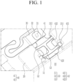
FIG. 1 is a partial perspective view of a rechargeable battery module according to an embodiment. -
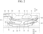
FIG. 2 is a partial perspective view showing a flexible printed circuit, a temperature sensing tab, and an elastic member in a rechargeable battery module according to an embodiment. -
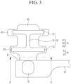
FIG. 3 is a top plan view of the flexible printed circuit, the temperature sensing tab, and the elastic member shown inFIG. 2 . -
FIG. 4 is a cross-sectional view taken along the line IV-IV inFIG. 3 . -
FIG. 5 is a top plan view of the flexible printed circuit, the temperature sensing tab, the elastic member, and a busbar holder according to an embodiment. -
FIG. 6 is a cross-sectional view taken along the line VI-VI inFIG. 5 . -
FIG. 7 is a perspective view of the temperature sensing tab shown inFIG. 3 . -
FIG. 8 is a cross-sectional view showing before and after states of a first coupling portion of an elastic member being coupled to a first catching portion of a temperature sensing tab. -
FIG. 9 is a cross-sectional view showing before and after states of a second coupling portion of an elastic member being coupled to a first catching portion of a temperature sensing tab. - The present invention will be described more fully hereinafter with reference to the accompanying drawings, in which embodiments of the present invention are shown. As those skilled in the art would realize, the described embodiments may be modified in various different ways. The drawings and description are to be regarded as illustrative in nature.
- It will be understood that when an element or layer is referred to as being "on," "connected to," or "coupled to" another element or layer, it may be directly on, connected, or coupled to the other element or layer or one or more intervening elements or layers may also be present. When an element or layer is referred to as being "directly on," "directly connected to," or "directly coupled to" another element or layer, there are no intervening elements or layers present. For example, when a first element is described as being "coupled" or "connected" to a second element, the first element may be directly coupled or connected to the second element or the first element may be indirectly coupled or connected to the second element via one or more intervening elements.
- In the figures, dimensions of the various elements, layers, etc. may be exaggerated for clarity of illustration. The same reference numerals designate the same elements. As used herein, the term "and/or" includes any and all combinations of one or more of the associated listed items. Further, the use of "may" when describing embodiments of the present disclosure relates to "one or more embodiments of the present disclosure." Expressions, such as "at least one of" and "any one of," when preceding a list of elements, modify the entire list of elements and do not modify the individual elements of the list. For example, the expression "at least one of a, b, or c" indicates only a, only b, only c, both a and b, both a and c, both b and c, all of a, b, and c, or variations thereof. As used herein, the terms "use," "using," and "used" may be considered synonymous with the terms "utilize," "utilizing," and "utilized," respectively. As used herein, the terms "substantially," "about," and similar terms are used as terms of approximation and not as terms of degree, and are intended to account for the inherent variations in measured or calculated values that would be recognized by those of ordinary skill in the art.
- It will be understood that, although the terms first, second, third, etc. may be used herein to describe various elements, components, regions, layers, and/or sections, these elements, components, regions, layers, and/or sections should not be limited by these terms. These terms are used to distinguish one element, component, region, layer, or section from another element, component, region, layer, or section. Thus, a first element, component, region, layer, or section discussed below could be termed a second element, component, region, layer, or section without departing from the teachings of example embodiments.
- Spatially relative terms, such as "beneath," "below," "lower," "above," "upper," and the like, may be used herein for ease of description to describe one element or feature's relationship to another element(s) or feature(s) as illustrated in the figures. It will be understood that the spatially relative terms are intended to encompass different orientations of the device in use or operation in addition to the orientation depicted in the figures. For example, if the device in the figures is turned over, elements described as "below" or "beneath" other elements or features would then be oriented "above" or "over" the other elements or features. Thus, the term "below" may encompass both an orientation of above and below. The device may be otherwise oriented (rotated 90 degrees or at other orientations), and the spatially relative descriptors used herein should be interpreted accordingly.
- The terminology used herein is for the purpose of describing embodiments of the present invention. As used herein, the singular forms "a" and "an" are intended to include the plural forms as well, unless the context clearly indicates otherwise. It will be further understood that the terms "includes," "including," "comprises," and/or "comprising," when used in this specification, specify the presence of stated features, integers, steps, operations, elements, and/or components but do not preclude the presence or addition of one or more other features, integers, steps, operations, elements, components, and/or groups thereof.
- In a rechargeable battery module, the position of the temperature sensing tab needs to be fixed to weld it to a battery cell. Accordingly, to fix the temperature sensing tab to a busbar holder, the temperature sensing tab may have a locking structure. However, during assembling, a defect may occur in that the temperature sensing tab may be deformed or the temperature sensing tab may not be engaged with the busbar holder.
- In addition, even if the temperature sensing tab is engaged with the busbar holder, welding defects may occur due to lifting of the temperature sensing tab from the battery cell. In addition, when welding the battery cell and the temperature sensing tab together, defects may occur depending on the welding condition, or foreign particles at the welding point may be present or may be generated, causing a defect.
-
FIG. 1 is a partial perspective view of a rechargeable battery module according to an embodiment.FIG. 2 is a partial perspective view primarily showing a flexible printed circuit, a temperature sensing tab, and an elastic member in the rechargeable battery module shown inFIG. 1 . Referring toFIG. 1 andFIG. 2 , a rechargeable battery module, according to an embodiment, may include abusbar holder 20 configured to cover a plurality ofbattery cells 10, a flexible printed circuit (FPC) 30, atemperature sensing tab 40, and anelastic member 50. - The
busbar holder 20 may be formed of an electrical insulation material (e.g., an electrically insulative material) and may be configured to cover the plurality ofbattery cells 10 to hold (or fix) the position of the busbars that electrically connect thebattery cells 10 to each other. The flexible printed circuit (FPC) 30 may be configured to detect the temperature of the busbars and thebattery cell 10 and to transmit the detected temperature, e.g. to a battery management system (BMS). As an example, the flexible printedcircuit 30 is configured to mount (or to receive or accommodate) atemperature sensor 31, and thetemperature sensor 31 may be covered by aninsulation material 32 to be electrically insulated. The flexible printedcircuit 30 may be provided on a lower surface or an upper surface of thebusbar holder 20. In the illustrated embodiment, the flexible printedcircuit 30 shown being on the upper surface of thebusbar holder 20 as an example. - The
temperature sensing tab 40 may include asensor connection portion 41 and acell contact portion 42 that are integrally formed. Thetemperature sensor 31 may be connected to thesensor connection portion 41. For example, because thetemperature sensor 31 is electrically connected to the flexible printedcircuit 30 and is mechanically in surface contact with thesensor connection portion 41, it may effectively detect a temperature (e.g., heat) of thebattery cell 10 through thesensor connection portion 41 and may transmit it through the flexible printedcircuit 30. - The
cell contact portion 42 may be coupled to thebusbar holder 20 to be in contact with thebattery cell 10. Accordingly, when thebusbar holder 20 covers thebattery cells 10, thecell contact portion 42 may be in stable contact with thebattery cell 10 and configured to detect the temperature of thebattery cell 10. In this state, the gap between thecell contact portion 42 and thebattery cell 10 is zero (0). - To further secure the
temperature sensing tab 40 to thebattery cell 10, theelastic member 50 may be coupled to thecell contact portion 42 and may elastically pressurize or press thecell contact portion 42. For example, because theelastic member 50 is coupled to thecell contact portion 42, which is coupled to thebusbar holder 20, and applies an elastic force to thecell contact portion 42 to resist against the force of thecell contact portion 42 floating from (or moving away from) thebattery cell 10, thecell contact portion 42 may elastically contact thebattery cell 10. The gap between thecell contact portion 42 and thebattery cell 10 may stably maintain at zero (0). -
FIG. 3 is a top plan view of the flexible printed circuit, the temperature sensing tab, and the elastic member shown inFIG. 2 .FIG. 4 is a cross-sectional view taken along the line IV-IV inFIG. 3 . Referring toFIG. 1 to FIG. 4 , thecell contact portion 42 includes acontact plate portion 423, a first catchingportion 421, and a second catchingportion 422. - The
contact plate portion 423 may be in direct contact with thebattery cell 10 to receive and transfer the heat of thebattery cell 10. Thecontact plate portion 423 may be formed to be integrally connected to thesensor connection portion 41. Accordingly, the heat of thebattery cell 10 detected at thecontact plate portion 423 may be transferred to thetemperature sensor 31, which is in contact with thesensor connection portion 41, through thesensor connection portion 41. - The first catching
portion 421 may be located in (e.g., may extend or protrude from) thecontact plate portion 423 away from (e.g., opposite to) thesensor connection portion 41 and may be disposed on thebusbar holder 20. Thesecond catching portion 422 may be spaced apart from the first catchingportion 421 and located in thecontact plate portion 423 near thesensor connection portion 41 and coupled under thebusbar holder 20. For example, thecontact plate portion 423 may be engaged with thebusbar holder 20 through the first and second catchingportions - The
contact plate portion 423 of thecell contact portion 42 may be in contact with thebattery cell 10. In this state, the first catchingportion 421 may be located in thecontact plate portion 423 away from thesensor connection portion 41 and disposed on thebusbar holder 20, and the first catchingportion 421 may be disposed on both sides of thecontact plate portion 423 in a width direction as a pair. - In addition, the second catching
portion 422 may be spaced apart from the first catchingportion 421, located in thecontact plate portion 423 near thesensor connection portion 41, and coupled under thebusbar holder 20, and the second catchingportion 422 may be disposed on both sides of thecontact plate portion 423 in the width direction as a pair. -
FIG. 8 is a cross-sectional view showing before and after states of a first coupling portion of an elastic member that is coupled to a first catching portion (e.g., in a generally horizontal state) of the temperature sensing tab.FIG. 9 is a cross-sectional view showing before and after states of a second coupling portion of an elastic member that is coupled to a first catching portion (e.g., in a generally inclined state) of the temperature sensing tab. - Referring to
FIGS. 1-4 ,FIG. 8 , andFIG. 9 , theelastic member 50 includes a firstelastic portion 51, a secondelastic portion 52, and aconnection portion 53. The firstelastic portion 51 may be coupled to the first catchingportion 421 at a first through hole H1 therein and may be configured to apply an elastic force to the first catchingportion 421. The secondelastic portion 52 may be coupled to the second catchingportion 422 at a second through hole H2 therein and may be configured to apply an elastic force to the second catchingportion 422. Theconnection portion 53 may interconnect the firstelastic portion 51 and the secondelastic portion 52 in a crossing direction and may ensure uniformness of the elastic force applied by the firstelastic portion 51 and the secondelastic portion 52. - The first
elastic portion 51 of theelastic member 50 may be coupled to each of the first through holes H1 in the pair of first catchingportions 421 and configured to apply an elastic force to the first catchingportion 421. In addition, the secondelastic portion 52 may be coupled to each of the second through holes H2 in the pair of second catchingportions 422 and configured to apply an elastic force to the second catchingportion 422. - Referring to
FIG. 9 , the pair of first catchingportions 421 may form a first gap G1 at the same height on thecontact plate portion 423, and the pair of second catchingportions 422 may form a second gap G2 that is greater than the first gap G1. - The pair of first catching
portions 421 is caught by (e.g., is restrained by) the upper surface of thebusbar holder 20 by the relatively short first gap G1, and the pair of second catchingportions 422 is caught by (e.g., is restrained by) a lower surface of thebusbar holder 20 by the relatively long second gap G2. Accordingly, thecontact plate portion 423 may maintain stable contact structure with respect to thebattery cell 10. -
FIG. 5 is a top plan view showing the flexible printed circuit, the temperature sensing tab, elastic member and the busbar holder ofFIG. 2 . Referring toFIG. 5 , for engagement of the first and second catchingportions busbar holder 20, thebusbar holder 20 may be provided with aseating groove 211 and ahook 212. Theseating groove 211 may be formed in a structure having an open top in the upper surface of thebusbar holder 20, correspond to the first catchingportion 421. Through this open structure, the first catchingportion 421 may be seated in theseating groove 211. -
FIG. 6 is a cross-sectional view taken along the line VI-VI inFIG. 5 . Referring toFIG. 6 , thehook 212 may be arranged in an open bottom area of the lower surface of thebusbar holder 20, corresponding to the second catchingportion 422. Through this structure, the second catchingportion 422 may be caught by thehook 212. Accordingly, the first and second catchingportions seating groove 211 and thehook 212 in upper and lower surfaces of thebusbar holder 20, respectively, . - In addition, the first catching
portion 421 is formed in a horizontal state and disposed on theseating groove 211, and the second catchingportion 422 is formed in an inclined state and caught under thehook 212. The pair of first catchingportions 421 is caught by theseating groove 211 in the upper surface of thebusbar holder 20, and the pair of second catchingportions 422 is caught by thehook 212 in the lower surface of thebusbar holder 20. Accordingly, thecontact plate portion 423 may maintain a stable contact structure with respect to thebattery cell 10. - Referring to
FIG. 4 andFIG. 6 , the second catchingportion 422 may form a first angle θ1 in a free state, that may be a free state of the second catchingportion 422, by being bent from thecontact plate portion 423, and when it is caught by thehook 212, may form a second angle θ2 that is greater than the first angle θ1. For example, as the second catchingportion 422 is gathered to (e.g., is pushed toward) the center by thehook 212, an outer angle between the second catchingportion 422 and thebattery cell 10 may be increased. - The
second catching portion 422 may be spread under thehook 212 because thehook 212 is inserted from above, and the second angle, in the inserted state, may be smaller than the first angle in the free state. -
FIG. 7 is a perspective view of the temperature sensing tab shown inFIG. 3 . Referring toFIG. 7 to FIG. 9 , the secondelastic portion 52 may be formed in a curved shape (e.g., in a curved line) convex toward thecell contact portion 42 in the free state and may provide an elastic force toward thecell contact portion 42 in a state in which it is coupled to the second catchingportion 422 caught by thehook 212. The free state may be a free state of the secondelastic portion 52. - Referring to
FIG. 6 , an elastic force F provided to thecell contact portion 42 through the second catchingportion 422 by the secondelastic portion 52 may be highest at a center of the cell contact portion 42 (e.g., the center ofFIG. 6 in the left-and-right direction) and may decrease toward both ends. - Referring to
FIG. 4 , the first catchingportion 421 may form the angle θ that is greater than the first angle θ1 in the free state by being bent from thecontact plate portion 423. The free state may be a free state of the first catchingportion 421. As shown inFIG. 9 , in the state in which the second catchingportion 422 is coupled to thehook 212, the second catchingportion 422 may form the second angle θ2, and the second angle θ2 is similar to the angle θ in the state in which the first catchingportion 421 is seated on the seating groove 211 (see, e.g.,FIG. 9 ). For example, the first and second catchingportions - The first
elastic portion 51 may have a curved shape (e.g., may have a curved line shape) convex toward thecontact plate portion 423 in the free state and may provide an elastic force toward thecell contact portion 42 in a state in which it is coupled to the first catchingportion 421 disposed in theseating groove 211. The free state may be a free state oof the firstelastic portion 51. - The elastic force provided to the
cell contact portion 42 by the first catchingportion 421, which receives the elastic force of the firstelastic portion 51, may be highest at a center of the cell contact portion 42 (the center ofFIG. 6 in the left-and-right direction) and may decrease toward both ends. This may be seen from the elastic force F of the second catchingportion 422 by the secondelastic portion 52 shown in, for example,FIG. 6 . - Because the first and second
elastic portions elastic member 50 pressurize or press the first catchingportion 421 and the second catchingportion 422, respectively, such that thecontact plate portion 423 may be elastically supported by and in contact with thebattery cell 10, welding thecontact plate portion 423 and thebattery cell 10 is unnecessary. Accordingly, defects that may be caused by welding may be eliminated. In addition, costs, such as the process cost and quality management cost due welding, may be eliminated. While the present disclosure has been described in connection with what is presently considered to be practical embodiments, it is to be understood that the present disclosure is not limited to the disclosed embodiments but, on the contrary, is intended to cover various modifications included within the scope of the appended claims.Reference Numerals 10: battery cell 20: the busbar holder 30: flexible printed circuit (FPC) 31: temperature sensor 32: insulation material 40: the temperature sensing tab 41: sensor connection portion 42: cell contact portion 50: elastic member 51: first elastic portion 52: second elastic portion 53: connection portion 211: seating groove 212: hook 421: first catching portion 422: second catching portion 423: contact plate portion F: elastic force G1: first gap G2: second gap H1: 1 first through hole H2: second through hole θ: angle θ1: first angle θ2: second angle
Claims (15)
- A rechargeable battery module comprising:a busbar holder (20) configured to cover a plurality of battery cells (10);a flexible printed circuit (30), FPC, configured to transmit a signal corresponding to a detected temperature of at least one of the battery cells (10) from a temperature sensor (31) mounted on the busbar holder (20);a temperature sensing tab (40) comprising a sensor connection portion (41) at a first side that is connected to the temperature sensor (31) and a cell contact portion (42) at a second side that is coupled to the busbar holder (20) and in contact with the at least one of the battery cells (10); andan elastic member (50) coupled to the cell contact portion (42) and configured to elastically pressurize the cell contact portion (42) onto the at least one of the battery cells (10).
- The rechargeable battery module of claim 1, wherein the cell contact portion (42) comprises:a contact plate portion (423) in contact with the at least one of the battery cells (10);a first catching portion (421) in the contact plate portion (423) at a side away from or opposite to the sensor connection portion (41) and on the busbar holder (20); anda second catching portion (422) spaced apart from the first catching portion (421) and in the contact plate portion (423) nearer to the sensor connection portion (41) than the first catching portion (421) and coupled under the busbar holder (20).
- The rechargeable battery module of claim 2, wherein the elastic member (50) comprises:a first elastic portion (51) coupled at a first through hole in the first catching portion (421) and configured to apply an elastic force to the first catching portion (421); anda second elastic portion (52) coupled at a second through hole in the second catching portion (422) and configured to apply an elastic force to the second catching portion (422).
- The rechargeable battery module of claim 3, wherein the elastic member (50) further comprises a connection portion (53) interconnecting the first elastic portion (51) and the second elastic portion (52) in a crossing direction.
- The rechargeable battery module of claim 2, wherein the busbar holder (20) comprises:a seating groove (211) having an open top corresponding to the first catching portion (421); anda hook (212) having an open bottom corresponding to the second catching portion (422).
- The rechargeable battery module of claim 5, wherein the first catching portion (421) extends in a horizontal direction in the seating groove (211), and
wherein the second catching portion (422) extends in an inclined direction and is restrained under the hook (212). - The rechargeable battery module of claim 5 or 6, wherein the second catching portion (422) is configured to:in a first state, form a first angle by being bent from the contact plate portion (423); andin a second state when caught by the hook (212), form a second angle that is greater than the first angle.
- The rechargeable battery module of claim 6 or 7, wherein a second elastic portion (52) of the elastic member (50) has a curved shape convex toward the contact plate portion (423) in its free state and is configured to provide an elastic force toward the contact plate portion (423) in a state in which it is coupled to the second catching portion (422) restrained by the hook (212).
- The rechargeable battery module of claim 8, wherein the elastic force provided to the contact plate portion (423) through the second catching portion (422) by the second elastic portion (52) is highest at a center of the contact plate portion (423) and decreases toward both ends.
- The rechargeable battery module of any of claims 7 to 9, wherein, in its free state, the first catching portion (421) is configured to form an angle that is greater than the first angle by being bent from the contact plate portion (423).
- The rechargeable battery module of any of claims 7 to 10, wherein, in its free state, a first elastic portion (51) of the elastic member (50) has a curved shape convex toward the contact plate portion (423) and is configured to provide an elastic force toward the contact plate portion (423) in a state in which it is coupled to the first catching portion (421) in the seating groove (211).
- The rechargeable battery module of claim 11, wherein the elastic force provided to the contact plate portion (423) through the first catching portion (421) by the first elastic portion (51) is highest at a center of the contact plate portion (423) and decreases toward both ends.
- The rechargeable battery module of claim 1, wherein the cell contact portion (42) comprises:a contact plate portion (423) in contact with the at least one of the battery cells (10);a pair of first catching portions (421) respectively extending from opposite sides of the contact plate portion (423) in a width direction at an area of the contact plate portion (423) away from the sensor connection portion (41), the first catching portions (421) being on the busbar holder (20); anda pair of second catching portions (422) respectively extending from the opposite sides of the contact plate portion (423) in the width direction at another area of the contact plate portion (423) nearer to the sensor connection portion (41), the second catching portions (422) being coupled under the busbar holder (20).
- The rechargeable battery module of claim 13, wherein the elastic member (50) comprises:a first elastic portion (51) coupled to each of first through holes respectively in the pair of first catching portions (421) and configured to apply an elastic force to the first catching portion (421); anda second elastic portion (52) coupled to each of second through holes respectively in the pair of second catching portions (422) and configured to apply an elastic force to the second catching portion (422).
- The rechargeable battery module of claim 13 or 14, wherein, at the same height on the contact plate portion (423):the pair of first catching portions (421) form a first gap; andthe pair of second catching portions (422) form a second gap that is greater than the first gap.
Applications Claiming Priority (1)
| Application Number | Priority Date | Filing Date | Title |
|---|---|---|---|
| KR1020240002488A KR20250107639A (en) | 2024-01-05 | 2024-01-05 | Rechargeable battery module |
Publications (2)
| Publication Number | Publication Date |
|---|---|
| EP4583219A2 true EP4583219A2 (en) | 2025-07-09 |
| EP4583219A3 EP4583219A3 (en) | 2025-08-20 |
Family
ID=93924134
Family Applications (1)
| Application Number | Title | Priority Date | Filing Date |
|---|---|---|---|
| EP24219803.4A Pending EP4583219A3 (en) | 2024-01-05 | 2024-12-13 | Rechargeable battery module |
Country Status (4)
| Country | Link |
|---|---|
| US (1) | US20250226553A1 (en) |
| EP (1) | EP4583219A3 (en) |
| KR (1) | KR20250107639A (en) |
| CN (1) | CN120280588A (en) |
Family Cites Families (4)
| Publication number | Priority date | Publication date | Assignee | Title |
|---|---|---|---|---|
| CN210628444U (en) * | 2019-11-25 | 2020-05-26 | 宁德时代新能源科技股份有限公司 | Battery module, battery pack, and vehicle |
| KR20220130425A (en) * | 2021-03-18 | 2022-09-27 | 삼성에스디아이 주식회사 | Hybrid circuit board and battery pack having same |
| KR20230149514A (en) * | 2022-04-20 | 2023-10-27 | 에스케이온 주식회사 | Battery Module Having Sensing Module Assembly |
| KR20250040219A (en) * | 2023-09-15 | 2025-03-24 | 삼성에스디아이 주식회사 | Battery module |
-
2024
- 2024-01-05 KR KR1020240002488A patent/KR20250107639A/en active Pending
- 2024-11-14 US US18/948,271 patent/US20250226553A1/en active Pending
- 2024-12-13 EP EP24219803.4A patent/EP4583219A3/en active Pending
- 2024-12-20 CN CN202411887356.1A patent/CN120280588A/en active Pending
Also Published As
| Publication number | Publication date |
|---|---|
| US20250226553A1 (en) | 2025-07-10 |
| CN120280588A (en) | 2025-07-08 |
| EP4583219A3 (en) | 2025-08-20 |
| KR20250107639A (en) | 2025-07-14 |
Similar Documents
| Publication | Publication Date | Title |
|---|---|---|
| US12211975B2 (en) | Battery module having connector mounted on FPCB, and battery pack and vehicle comprising same | |
| US20230112307A1 (en) | Battery pack | |
| US9716258B2 (en) | Battery pack | |
| US12610468B2 (en) | Hybrid circuit board and battery pack having same | |
| US10096865B2 (en) | Secondary cell module | |
| JP7570754B2 (en) | Electrode lead bending and welding device and electrode lead welding method using the same | |
| KR20180113814A (en) | Battery module, battery pack including the same, and vehicle including the same | |
| US20220085447A1 (en) | Battery module and battery pack including the same | |
| US20250153262A1 (en) | Welding Apparatus and Welding Method | |
| US20230088451A1 (en) | Battery pack and manufacturing method of battery pack | |
| KR102942276B1 (en) | Battery module | |
| EP4583219A2 (en) | Rechargeable battery module | |
| US11394087B2 (en) | Battery module | |
| EP4404330B1 (en) | Rechargeable battery module | |
| US20240186663A1 (en) | Battery cell and battery pack including the same | |
| EP4586362A2 (en) | Rechargeable battery module | |
| US12290877B2 (en) | Method for producing a traction battery of a motor vehicle and corresponding production device | |
| US20250343314A1 (en) | Battery module | |
| US20240332758A1 (en) | Battery pack and method of manufacturing the battery pack | |
| EP4517924A1 (en) | Temperature sensing assembly, and battery module comprising same | |
| US20250385329A1 (en) | Battery module | |
| EP4075581B1 (en) | Battery module and battery pack including the same | |
| EP4564530A2 (en) | Battery cell heating apparatus and battery module | |
| EP4407771A2 (en) | Rechargeable battery pack | |
| US20230261309A1 (en) | Rechargeable Battery System |
Legal Events
| Date | Code | Title | Description |
|---|---|---|---|
| PUAI | Public reference made under article 153(3) epc to a published international application that has entered the european phase |
Free format text: ORIGINAL CODE: 0009012 |
|
| STAA | Information on the status of an ep patent application or granted ep patent |
Free format text: STATUS: REQUEST FOR EXAMINATION WAS MADE |
|
| 17P | Request for examination filed |
Effective date: 20241213 |
|
| AK | Designated contracting states |
Kind code of ref document: A2 Designated state(s): AL AT BE BG CH CY CZ DE DK EE ES FI FR GB GR HR HU IE IS IT LI LT LU LV MC ME MK MT NL NO PL PT RO RS SE SI SK SM TR |
|
| PUAL | Search report despatched |
Free format text: ORIGINAL CODE: 0009013 |
|
| AK | Designated contracting states |
Kind code of ref document: A3 Designated state(s): AL AT BE BG CH CY CZ DE DK EE ES FI FR GB GR HR HU IE IS IT LI LT LU LV MC ME MK MT NL NO PL PT RO RS SE SI SK SM TR |
|
| RIC1 | Information provided on ipc code assigned before grant |
Ipc: H01M 10/04 20060101AFI20250717BHEP Ipc: H01M 10/42 20060101ALI20250717BHEP Ipc: H01M 10/48 20060101ALI20250717BHEP Ipc: H01M 50/209 20210101ALI20250717BHEP Ipc: H01M 50/284 20210101ALI20250717BHEP Ipc: H01M 50/569 20210101ALI20250717BHEP |