EP4583218A1 - Mandrel member of winder for secondary battery - Google Patents
Mandrel member of winder for secondary battery Download PDFInfo
- Publication number
- EP4583218A1 EP4583218A1 EP24201969.3A EP24201969A EP4583218A1 EP 4583218 A1 EP4583218 A1 EP 4583218A1 EP 24201969 A EP24201969 A EP 24201969A EP 4583218 A1 EP4583218 A1 EP 4583218A1
- Authority
- EP
- European Patent Office
- Prior art keywords
- mandrel member
- slits
- cylindrical body
- end portion
- peripheral surface
- Prior art date
- Legal status (The legal status is an assumption and is not a legal conclusion. Google has not performed a legal analysis and makes no representation as to the accuracy of the status listed.)
- Granted
Links
Images




Classifications
-
- B—PERFORMING OPERATIONS; TRANSPORTING
- B65—CONVEYING; PACKING; STORING; HANDLING THIN OR FILAMENTARY MATERIAL
- B65H—HANDLING THIN OR FILAMENTARY MATERIAL, e.g. SHEETS, WEBS, CABLES
- B65H18/00—Winding webs
- B65H18/08—Web-winding mechanisms
- B65H18/10—Mechanisms in which power is applied to web-roll spindle
-
- H—ELECTRICITY
- H01—ELECTRIC ELEMENTS
- H01M—PROCESSES OR MEANS, e.g. BATTERIES, FOR THE DIRECT CONVERSION OF CHEMICAL ENERGY INTO ELECTRICAL ENERGY
- H01M10/00—Secondary cells; Manufacture thereof
- H01M10/04—Construction or manufacture in general
- H01M10/0404—Machines for assembling batteries
- H01M10/0409—Machines for assembling batteries for cells with wound electrodes
-
- H—ELECTRICITY
- H01—ELECTRIC ELEMENTS
- H01M—PROCESSES OR MEANS, e.g. BATTERIES, FOR THE DIRECT CONVERSION OF CHEMICAL ENERGY INTO ELECTRICAL ENERGY
- H01M10/00—Secondary cells; Manufacture thereof
- H01M10/05—Accumulators with non-aqueous electrolyte
- H01M10/058—Construction or manufacture
- H01M10/0587—Construction or manufacture of accumulators having only wound construction elements, i.e. wound positive electrodes, wound negative electrodes and wound separators
-
- B—PERFORMING OPERATIONS; TRANSPORTING
- B65—CONVEYING; PACKING; STORING; HANDLING THIN OR FILAMENTARY MATERIAL
- B65H—HANDLING THIN OR FILAMENTARY MATERIAL, e.g. SHEETS, WEBS, CABLES
- B65H39/00—Associating, collating, or gathering articles or webs
- B65H39/16—Associating two or more webs
-
- H—ELECTRICITY
- H01—ELECTRIC ELEMENTS
- H01M—PROCESSES OR MEANS, e.g. BATTERIES, FOR THE DIRECT CONVERSION OF CHEMICAL ENERGY INTO ELECTRICAL ENERGY
- H01M10/00—Secondary cells; Manufacture thereof
- H01M10/04—Construction or manufacture in general
- H01M10/0431—Cells with wound or folded electrodes
-
- H—ELECTRICITY
- H01—ELECTRIC ELEMENTS
- H01M—PROCESSES OR MEANS, e.g. BATTERIES, FOR THE DIRECT CONVERSION OF CHEMICAL ENERGY INTO ELECTRICAL ENERGY
- H01M10/00—Secondary cells; Manufacture thereof
- H01M10/05—Accumulators with non-aqueous electrolyte
- H01M10/052—Li-accumulators
-
- B—PERFORMING OPERATIONS; TRANSPORTING
- B65—CONVEYING; PACKING; STORING; HANDLING THIN OR FILAMENTARY MATERIAL
- B65H—HANDLING THIN OR FILAMENTARY MATERIAL, e.g. SHEETS, WEBS, CABLES
- B65H2301/00—Handling processes for sheets or webs
- B65H2301/40—Type of handling process
- B65H2301/41—Winding, unwinding
- B65H2301/414—Winding
- B65H2301/41419—Starting winding process
- B65H2301/41429—Starting winding process in coreless applications
-
- B—PERFORMING OPERATIONS; TRANSPORTING
- B65—CONVEYING; PACKING; STORING; HANDLING THIN OR FILAMENTARY MATERIAL
- B65H—HANDLING THIN OR FILAMENTARY MATERIAL, e.g. SHEETS, WEBS, CABLES
- B65H2701/00—Handled material; Storage means
- B65H2701/10—Handled articles or webs
- B65H2701/19—Specific article or web
-
- H—ELECTRICITY
- H01—ELECTRIC ELEMENTS
- H01M—PROCESSES OR MEANS, e.g. BATTERIES, FOR THE DIRECT CONVERSION OF CHEMICAL ENERGY INTO ELECTRICAL ENERGY
- H01M10/00—Secondary cells; Manufacture thereof
- H01M10/05—Accumulators with non-aqueous electrolyte
- H01M10/052—Li-accumulators
- H01M10/0525—Rocking-chair batteries, i.e. batteries with lithium insertion or intercalation in both electrodes; Lithium-ion batteries
-
- Y—GENERAL TAGGING OF NEW TECHNOLOGICAL DEVELOPMENTS; GENERAL TAGGING OF CROSS-SECTIONAL TECHNOLOGIES SPANNING OVER SEVERAL SECTIONS OF THE IPC; TECHNICAL SUBJECTS COVERED BY FORMER USPC CROSS-REFERENCE ART COLLECTIONS [XRACs] AND DIGESTS
- Y02—TECHNOLOGIES OR APPLICATIONS FOR MITIGATION OR ADAPTATION AGAINST CLIMATE CHANGE
- Y02E—REDUCTION OF GREENHOUSE GAS [GHG] EMISSIONS, RELATED TO ENERGY GENERATION, TRANSMISSION OR DISTRIBUTION
- Y02E60/00—Enabling technologies; Technologies with a potential or indirect contribution to GHG emissions mitigation
- Y02E60/10—Energy storage using batteries
-
- Y—GENERAL TAGGING OF NEW TECHNOLOGICAL DEVELOPMENTS; GENERAL TAGGING OF CROSS-SECTIONAL TECHNOLOGIES SPANNING OVER SEVERAL SECTIONS OF THE IPC; TECHNICAL SUBJECTS COVERED BY FORMER USPC CROSS-REFERENCE ART COLLECTIONS [XRACs] AND DIGESTS
- Y02—TECHNOLOGIES OR APPLICATIONS FOR MITIGATION OR ADAPTATION AGAINST CLIMATE CHANGE
- Y02P—CLIMATE CHANGE MITIGATION TECHNOLOGIES IN THE PRODUCTION OR PROCESSING OF GOODS
- Y02P70/00—Climate change mitigation technologies in the production process for final industrial or consumer products
- Y02P70/50—Manufacturing or production processes characterised by the final manufactured product
Definitions
- Embodiments of the present disclosure relate to a mandrel member of a winder for a secondary battery, and more specifically, to a mandrel member configured to manufacture a jelly roll-type electrode assembly and a winder comprising the same.
- such a secondary battery includes an electrode assembly, a battery case that accommodates the electrode assembly and an electrolyte, and a cap assembly that is coupled to an upper opening of the battery case to seal the case and allow a current generated in the electrode assembly to flow to an external device.
- a secondary battery mainly uses lithium-based oxide as a positive electrode active material and a carbon material as a negative electrode active material.
- batteries may be classified into liquid electrolyte batteries and polymer electrolyte batteries according to types of electrolytes. Batteries using a liquid electrolyte may be referred to as lithium ion batteries, and batteries using a polymer electrolyte may be referred to as lithium polymer batteries.
- Lithium secondary batteries may be manufactured in various shapes. According to shapes of battery cases, lithium secondary batteries may be classified into cylindrical and prismatic batteries in which an electrode assembly is embedded in a cylindrical or prismatic metal can, and pouch-type batteries in which an electrode assembly is embedded in a pouch-type case of an aluminum stack sheet.
- an electrode assembly embedded in a battery case is a chargeable or dischargeable power generation element having a stacked structure of a positive electrode, a separator, and a negative electrode.
- the electrode assembly is classified into a jelly roll-type electrode assembly formed by winding a positive electrode and a negative electrode with a separator interposed between the positive electrode and the negative electrode which are long sheet-type electrodes coated with an active material, and a stack-type electrode assembly by sequentially stacking a plurality of positive electrodes, a plurality of negative electrodes, which have a certain size, and a plurality of separators interposed therebetween.
- a process of manufacturing a jelly roll-type electrode assembly includes a winding process in which an end portion of a sheet-type stack including a positive electrode, a separator, and a negative electrode is inserted into and fixed to a mandrel member and wound in a cylindrical shape, and then the mandrel is removed, and a reform process in which a center pin is inserted into the center of a jelly roll-type electrode assembly from which the mandrel is removed.
- FIG. 1A schematically illustrates a structure of a comparative mandel used in a winding process.
- a mandrel 10 is an overall cylindrical pillar-shaped member, and one end portion thereof is split into two semicircles at a central portion such that a sheet-type stack may be inserted therein. If viewed in a cross section, the end portion has a taegeuk pattern structure in which two semicircles 11a and 11b face each other.
- a planar cut surface may be partially formed on an outer surface of one of the semicircles such that an electrode tab and protective tape of the sheet-type stack may be positioned.
- the center pin is generally made of a metal material to have a certain level of strength, has a structure in which a plate is bent round, and has a hollow cylindrical structure in which upper ends of a horizontal cross section may not be in contact with each other.
- an electrode assembly is fixed to a jig (not shown), and the center pin advances or retreats toward a hollow central portion of the fixed electrode assembly.
- a separator positioned at a central portion is pushed toward an inner peripheral surface of the central portion, and the separator with a taegeuk pattern is removed.
- FIG. 1B is an image showing a jelly roll-type electrode assembly in which a reform loosening phenomenon is found after a reform process.
- a separator becomes thinner and a size of a mandrel decreases, a separator loosening phenomenon occurs more frequently.
- a positive electrode tab/negative electrode welding process is performed after a reform process, but as a reform loosening phenomenon occurs, there are many cases in which the quality of welding of the electrode tabs is also poor.
- Embodiments include a mandrel member of a winder for a secondary battery, which is mounted in a winder configured to manufacture a jelly roll-type electrode assembly by winding a stack of a first electrode plate, a separator, and a second electrode plate, the mandrel member including a cylindrical body having a hollow portion, wherein the cylindrical body includes a plurality of slits o cross the cylindrical body in a hollow axis direction so that the hollow portion inside the cylindrical body may be in fluid communication with the outside of the cylindrical body.
- Each slit may be oriented to have an inclination with respect to a radial direction so that air passing through the hollow portion leaks out through the plurality of slits in a substantially tangential direction with respect to an outer peripheral surface of the cylindrical body.
- the mandrel member may be one member and the plurality of slits may be formed at equal intervals in a circumferential direction, and wherein each of the plurality of slits may have a curved shape.
- An even number of slits may be formed at equal intervals in a circumferential direction and have an arrangement structure in which facing slits may be symmetrical with each other.
- Each slit may have an oblique inclination in a direction opposite to a rotation direction of the mandrel member.
- the mandrel member may be a hollow cylindrical body of which a vertical cross-sectional outer diameter is 6 ⁇ , each of the slits may have an arc shape of a virtual circle with a diameter of 4 ⁇ , and centers of each virtual circle forming the plurality of slits may be present on a virtual concentric circle.
- the mandrel member may include a plurality of blade units, which in a longitudinal direction, to have the plurality of slits at preset intervals.
- a trailing end portion of one blade unit in a width direction and a leading end portion of an adjacent blade unit in a width direction may overlap each other to have one of the preset intervals to form the plurality of slits.
- the mandrel member may include six blade units.
- Each blade unit may have a structure in which an outer peripheral surface and an inner peripheral surface may be curved inward in the width direction, a curvature of the outer peripheral surface may be less than a curvature of the inner peripheral surface, and an outer peripheral surface of the trailing end portion of one blade unit in the width direction and an inner peripheral surface of the leading end portion of the adjacent blade unit in the width direction may overlap each other to form a slit of the plurality of slits having a curved shape.
- a leading end portion of the mandrel member may be mounted on an air supplier provided in the winder, and air discharged from the air supplier may enter the hollow portion from the leading end portion of the mandrel member, the air flowing into the hollow portion may branch into a plurality of portions through the plurality of slits and may be ejected outward in a radial direction of the cylindrical body, and the remaining air may be discharged to the outside from a trailing end portion of the mandrel member.
- a winder for manufacturing a jelly roll-type electrode assembly of a secondary battery is configured to wind a stack of a first electrode plate, a separator, and a second electrode plate to form a jelly roll-type electrode assembly.
- the winder comprises a mandrel member including a cylindrical body having a hollow portion, wherein the cylindrical body includes a plurality of slits o cross the cylindrical body in a hollow axis direction so that the hollow portion inside the cylindrical body may be in fluid communication with the outside of the cylindrical body.
- the winder may further comprise an air supplier, wherein a leading end portion of the mandrel member is mounted on the air supplier.
- the term "and/or” includes any and all combinations of one or more of the associated listed items. Also, in this specification, it will be understood that if an element A is referred to as being "connected to" an element B, the element A can be directly connected to the element B, or an intervening element C may be present between the elements A and B so that the element A can be indirectly connected to the element B.
- the terminologies used herein are for the purpose of describing particular embodiments only and are not intended to be limiting of the present disclosure. As used herein, the singular forms are intended to include the plural forms as well, unless the context clearly indicates otherwise.
- first, second, etc. may be used herein to describe various members, components, regions, layers, and/or portions, these members, components, regions, layers, and/or portions should not be limited by these terms. These terms are only used to distinguish one member, component, region, layer, or portion from another region, layer, or portion. Thus, a first member, component, region, layer, or portion which will be described below may also refer to a second member, component, region, layer, or portion, without departing from the teaching of the present disclosure.
- the winder may manufacture an electrode assembly by winding the first electrode plate 21, the second electrode plate 23, and a first separator 22, and additionally winding a second separator 22.
- the winder may include first to fourth supply rolls R1, R2, R3, and R4, first to fourth transfer rolls R11, R21, R31, and R41, a nip roll R5, and the mandrel member 100.
- the first electrode plate 21 and the second electrode plate 23, which may have a band shape, are wound around the first supply roll R1 and the second supply roll R2, respectively, and the separators 22 having a band shape may be wound around the third supply roll R3 and the fourth supply roll R4.
- the mandrel member 100 of the present disclosure does not have a separate groove for fixing the sheet-type stack 20, but includes an empty space 120 (hollow portion) at a central portion of the mandrel member 100 extending in an axis direction (hereinafter referred to as the hollow axis) of the mandrel member 100.
- slits 110 may be formed to cross the cylindrical body in the hollow axis direction so that the hollow portion 120 inside the cylindrical body may be in fluid communication with the outside of the cylindrical body.
- a plurality of slits 110 may extend in a longitudinal direction (direction parallel to the hollow axis) in a cylindrical sidewall of the mandrel member 100, and respective slits 110 may be formed at equal intervals in a circumferential direction.
- six slits 110 may be formed as an example.
- each slit 110 may pass through a sidewall of the cylindrical body so that the hollow portion 120 of the cylindrical body may be in fluid communication with the outside of the sidewall of the cylindrical body.
- each slit 110 may be oriented to have an inclination with respect to a radial direction.
- each slit 110 may have an oblique inclination with respect to a normal direction radially facing outward from the hollow axis toward one side, that is, in a direction opposite to a rotation direction of the mandrel member 100.
- An angle of the inclination gradually may increase in a direction away from the hollow axis, and thus the slit 110 has a curved shape if viewed in a cross section.
- the mandrel member 100 has the plurality of slits 110 passing through a cylindrical wall, and the hollow portion 120 of the cylindrical body may be in fluid communication with (e.g., vent to) the outside of the sidewall of the cylindrical body through the slits 110.
- air discharged from the air supplier enters the hollow portion 120 from a leading end portion of the mandrel member 100 and may be discharged to the outside from a trailing end portion of the mandrel member 100.
- air flowing into the hollow portion 120 branches into a plurality of air portions through the plurality of slits 110 and may be ejected outward in a radial direction of the cylindrical body as indicated by an arrow in FIG.
- a pressure of air supplied to the hollow portion 120 may be high pressure and a chink of the slit 110 may be narrow, a pressure of air ejected to the outside of the cylindrical body becomes quite high.
- a pressure of air ejected to the outside of the cylindrical body becomes quite high.
- each slit 110 has a curved shape if viewed in a cross section, directionality may be provided if air is ejected outward.
- the Coanda effect may occur near an outer peripheral surface of the cylindrical body.
- the Coanda effect refers to a phenomenon in which, if a fluid flows in contact with a curved surface, the fluid flows along a curvature of the curved surface instead of flowing in a straight line.
- the mandrel member 100 has the shape of the cylindrical body, the outer peripheral surface thereof may be a curved surface, and each slit may be oriented to have an inclination with respect to the radial direction.
- the air from the air supplier may be supplied to the hollow portion 120 only while the sheet-type stack 20 is in contact with the outer peripheral surface of the cylindrical body of the mandrel member 100 and the mandrel member 100 rotates once for the first time. While the mandrel member 100 rotates once, the sheet-type stack 20 surrounds the outer peripheral surface of the mandrel member 100 by the Coanda effect, and in this way, if the sheet-type stack 20 is first fixed to the mandrel member 100, the supply of air may be stopped, and then the physical winding of the stack 20 may be performed by the rotation of the mandrel member 100. According to such a configuration, an insertion groove for inserting and fixing the sheet-type stack 20 does not need to be provided in the mandrel member 100.
- the mandrel member 100 according to one or more embodiments of the present disclosure is shown in FIG. 4A .
- the mandrel member 100 according to the present embodiment may be provided as one member, and the plurality of slits 110 may be formed at equal intervals in the circumferential direction, and each slit 110 may have a curved shape.
- six slits 110 may be formed in the circumferential direction.
- the air supplied to the hollow portion 120 of the mandrel member 100 may be discharged to the outside of the cylindrical body through the curved inclined slit 110, and may be discharged in a direction toward the outer peripheral surface, substantially in a direction in contact with the outer peripheral surface. Accordingly, the discharged air has directionality as shown at the central part of FIG.
- An even number of slits may be formed at equal intervals in the circumferential direction to have a structure in which facing slits may be symmetrical with each other.
- each slit may be formed in a shape of an arc of a virtual circle of which a diameter may be 2/3 of an outer diameter of the mandrel member, and the centers of the virtual circles forming respective slits may be present on a virtual concentric circle.
- the mandrel member may be a hollow cylindrical body of which a vertical cross-sectional outer diameter may be 6 ⁇ , and each slit may be formed in a shape of a virtual arc with a diameter of 4 ⁇ .
- a mandrel member 100 according to another embodiment of the present disclosure is shown in FIG. 4B .
- the mandrel member 100 according to the present embodiment may be formed such that a plurality of blade units 101 extending in a longitudinal direction may be disposed to achieve the plurality of slits 110 at preset intervals.
- a plurality of slits 110 may be formed at equal intervals in a circumferential direction, and each slit 110 has a curved shape.
- six blade units 101 may be in the circumferential direction, and a pair of adjacent blade units 101 may form one slit 110, thereby forming six slits 110.
- each blade unit 101 may have a structure in which an outer peripheral surface and an inner peripheral surface may be curved inward in a width direction, and a curvature of the outer peripheral surface may be less than a curvature of the inner peripheral surface.
- a trailing end portion of one blade unit 101 in a width direction and a leading end portion of an adjacent blade unit 101 in a width direction overlap each other in a preset manner to form one mandrel member 100 having a cylindrical shape.
- the formed interval constitutes the slit 110.
- a sheet-type stack 20 may be wound while attached in close contact with the mandrel member 100 having a cylindrical shape from the beginning by the Coanda effect, and thus during an existing process, a taegeuk-patterned separator is not formed at a central portion of a jelly roll-type electrode assembly. Therefore, there is no need to separately perform a reform process after a stack is wound.
- a sheet-type stack may be wound while attached in close contact with a mandrel member having a cylindrical shape from the beginning by the Coanda effect, and thus during an existing process, a taegeuk-patterned separator is not formed at a central portion of a jelly roll-type electrode assembly. Therefore, there is no need to separately perform a reform process after a stack is wound.
- the present disclosure provides a mandrel member having a new shape which improves a problem of a separator loosening at a central portion from which a mandrel may be removed after a winding process of an electrode assembly.
Landscapes
- Engineering & Computer Science (AREA)
- Manufacturing & Machinery (AREA)
- Chemical & Material Sciences (AREA)
- Chemical Kinetics & Catalysis (AREA)
- Electrochemistry (AREA)
- General Chemical & Material Sciences (AREA)
- Secondary Cells (AREA)
- Storage Of Web-Like Or Filamentary Materials (AREA)
Abstract
Description
- Embodiments of the present disclosure relate to a mandrel member of a winder for a secondary battery, and more specifically, to a mandrel member configured to manufacture a jelly roll-type electrode assembly and a winder comprising the same.
- Recently, as technology development and demand for mobile devices increase, the demand for secondary batteries as energy sources for compact and lightweight electric devices such as smartphones, laptop computers, and computers is rapidly increasing.
- Generally, such a secondary battery includes an electrode assembly, a battery case that accommodates the electrode assembly and an electrolyte, and a cap assembly that is coupled to an upper opening of the battery case to seal the case and allow a current generated in the electrode assembly to flow to an external device. Such a secondary battery mainly uses lithium-based oxide as a positive electrode active material and a carbon material as a negative electrode active material. Generally, batteries may be classified into liquid electrolyte batteries and polymer electrolyte batteries according to types of electrolytes. Batteries using a liquid electrolyte may be referred to as lithium ion batteries, and batteries using a polymer electrolyte may be referred to as lithium polymer batteries. Lithium secondary batteries may be manufactured in various shapes. According to shapes of battery cases, lithium secondary batteries may be classified into cylindrical and prismatic batteries in which an electrode assembly is embedded in a cylindrical or prismatic metal can, and pouch-type batteries in which an electrode assembly is embedded in a pouch-type case of an aluminum stack sheet.
- In addition, an electrode assembly embedded in a battery case is a chargeable or dischargeable power generation element having a stacked structure of a positive electrode, a separator, and a negative electrode. The electrode assembly is classified into a jelly roll-type electrode assembly formed by winding a positive electrode and a negative electrode with a separator interposed between the positive electrode and the negative electrode which are long sheet-type electrodes coated with an active material, and a stack-type electrode assembly by sequentially stacking a plurality of positive electrodes, a plurality of negative electrodes, which have a certain size, and a plurality of separators interposed therebetween.
- Among these, the jelly roll-type electrode assembly has an advantage of being easy to manufacture and having high energy density per weight. A process of manufacturing a jelly roll-type electrode assembly includes a winding process in which an end portion of a sheet-type stack including a positive electrode, a separator, and a negative electrode is inserted into and fixed to a mandrel member and wound in a cylindrical shape, and then the mandrel is removed, and a reform process in which a center pin is inserted into the center of a jelly roll-type electrode assembly from which the mandrel is removed.
-
FIG. 1A schematically illustrates a structure of a comparative mandel used in a winding process. Referring toFIG. 1A , amandrel 10 is an overall cylindrical pillar-shaped member, and one end portion thereof is split into two semicircles at a central portion such that a sheet-type stack may be inserted therein. If viewed in a cross section, the end portion has a taegeuk pattern structure in which twosemicircles - After a winding process of the sheet-type stack is completed, the
mandrel 10 is removed, and a center pin (not shown) is inserted into a space formed in a central portion of a jelly roll by removing the mandrel (reform process). The center pin is generally made of a metal material to have a certain level of strength, has a structure in which a plate is bent round, and has a hollow cylindrical structure in which upper ends of a horizontal cross section may not be in contact with each other. For example, an electrode assembly is fixed to a jig (not shown), and the center pin advances or retreats toward a hollow central portion of the fixed electrode assembly. In such a process, a separator positioned at a central portion is pushed toward an inner peripheral surface of the central portion, and the separator with a taegeuk pattern is removed. - However, if an electrode assembly is manufactured according to such a process, a problem has been found that a separator in close contact with an inner peripheral surface of a central portion is loosened before a negative electrode tab is welded.
FIG. 1B is an image showing a jelly roll-type electrode assembly in which a reform loosening phenomenon is found after a reform process. As a separator becomes thinner and a size of a mandrel decreases, a separator loosening phenomenon occurs more frequently. Typically, a positive electrode tab/negative electrode welding process is performed after a reform process, but as a reform loosening phenomenon occurs, there are many cases in which the quality of welding of the electrode tabs is also poor. - Embodiments include a mandrel member of a winder for a secondary battery, which is mounted in a winder configured to manufacture a jelly roll-type electrode assembly by winding a stack of a first electrode plate, a separator, and a second electrode plate, the mandrel member including a cylindrical body having a hollow portion, wherein the cylindrical body includes a plurality of slits o cross the cylindrical body in a hollow axis direction so that the hollow portion inside the cylindrical body may be in fluid communication with the outside of the cylindrical body.
- Each slit may be oriented to have an inclination with respect to a radial direction so that air passing through the hollow portion leaks out through the plurality of slits in a substantially tangential direction with respect to an outer peripheral surface of the cylindrical body.
- The mandrel member may be one member and the plurality of slits may be formed at equal intervals in a circumferential direction, and wherein each of the plurality of slits may have a curved shape.
- An even number of slits may be formed at equal intervals in a circumferential direction and have an arrangement structure in which facing slits may be symmetrical with each other.
- Each slit may have an oblique inclination in a direction opposite to a rotation direction of the mandrel member.
- The mandrel member may be a hollow cylindrical body of which a vertical cross-sectional outer diameter is 6 ϕ, each of the slits may have an arc shape of a virtual circle with a diameter of 4 Φ, and centers of each virtual circle forming the plurality of slits may be present on a virtual concentric circle.
- The mandrel member may include a plurality of blade units, which in a longitudinal direction, to have the plurality of slits at preset intervals.
- A trailing end portion of one blade unit in a width direction and a leading end portion of an adjacent blade unit in a width direction may overlap each other to have one of the preset intervals to form the plurality of slits.
- The mandrel member may include six blade units.
- Each blade unit may have a structure in which an outer peripheral surface and an inner peripheral surface may be curved inward in the width direction, a curvature of the outer peripheral surface may be less than a curvature of the inner peripheral surface, and an outer peripheral surface of the trailing end portion of one blade unit in the width direction and an inner peripheral surface of the leading end portion of the adjacent blade unit in the width direction may overlap each other to form a slit of the plurality of slits having a curved shape.
- A leading end portion of the mandrel member may be mounted on an air supplier provided in the winder, and air discharged from the air supplier may enter the hollow portion from the leading end portion of the mandrel member, the air flowing into the hollow portion may branch into a plurality of portions through the plurality of slits and may be ejected outward in a radial direction of the cylindrical body, and the remaining air may be discharged to the outside from a trailing end portion of the mandrel member.
- According to another aspect of the present invention, a winder for manufacturing a jelly roll-type electrode assembly of a secondary battery is configured to wind a stack of a first electrode plate, a separator, and a second electrode plate to form a jelly roll-type electrode assembly. The winder comprises a mandrel member including a cylindrical body having a hollow portion, wherein the cylindrical body includes a plurality of slits o cross the cylindrical body in a hollow axis direction so that the hollow portion inside the cylindrical body may be in fluid communication with the outside of the cylindrical body.
- The winder may further comprise an air supplier, wherein a leading end portion of the mandrel member is mounted on the air supplier.
- Features will become apparent to those of ordinary skill in the art by describing in detail exemplary embodiments with reference to the attached drawings, in which:
-
FIG. 1A schematically illustrates a structure of a mandrel used in a winding process according to a comparative example; -
FIG. 1B shows images showing a jelly roll-type electrode assembly in which a reform loosening phenomenon is found after a reform process is performed according to a comparative example; -
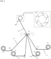
FIG. 2 is a schematic view illustrating a winder to which a mandrel member is applied according to one or more embodiments of the present disclosure; -
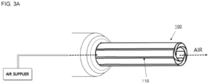
FIG. 3A is a conceptual view illustrating a mandrel member being mounted on a winding body according to one or more embodiments of the present disclosure; -
FIG. 3B shows a perspective view, a front view, and a cross-sectional view of the mandrel member according to one or more embodiments of the present disclosure; -
FIG. 4A shows cross-sectional views of the mandrel member according to one or more embodiments of the present disclosure; -
FIG. 4B shows cross-sectional views of a mandrel member according to one or more embodiments of the present disclosure; and -
FIG. 5 is a conceptual view illustrating a state in which a leading end portion of a sheet-type stack is close to the mandrel member ofFIG. 3A for a winding process according to one or more embodiments of the present disclosure. - Example embodiments will now be described more fully hereinafter with reference to the accompanying drawings; however, they may be embodied in different forms and should not be construed as limited to the embodiments set forth herein. Rather, these embodiments are provided so that this disclosure will be thorough and complete, and will fully convey exemplary implementations to those of ordinary skill in the art.
- In the drawing figures, the dimensions of layers and regions may be exaggerated for clarity of illustration. It will also be understood that if a layer or element is referred to as being "on" another layer or substrate, it can be directly on the other layer or substrate, or intervening layers may also be present. Further, it will be understood that if a layer is referred to as being "under" another layer, it can be directly under, and one or more intervening layers may also be present. In addition, it will also be understood that if a layer is referred to as being "between" two layers, it can be the only layer between the two layers, or one or more intervening layers may also be present. Like reference numerals refer to like elements throughout.
- As used in this specification, the term "and/or" includes any and all combinations of one or more of the associated listed items. Also, in this specification, it will be understood that if an element A is referred to as being "connected to" an element B, the element A can be directly connected to the element B, or an intervening element C may be present between the elements A and B so that the element A can be indirectly connected to the element B. The terminologies used herein are for the purpose of describing particular embodiments only and are not intended to be limiting of the present disclosure. As used herein, the singular forms are intended to include the plural forms as well, unless the context clearly indicates otherwise. Further, the terms "comprise and include" and/or "comprising and including" used in this specification should be interpreted as specifying the presence of described shapes, numbers, steps, operations, members, elements, and/or groups thereof and do not exclude the presence or addition of other shapes, numbers, steps, operations, members, elements, and/or groups thereof.
- It will be understood that, although the terms first, second, etc. may be used herein to describe various members, components, regions, layers, and/or portions, these members, components, regions, layers, and/or portions should not be limited by these terms. These terms are only used to distinguish one member, component, region, layer, or portion from another region, layer, or portion. Thus, a first member, component, region, layer, or portion which will be described below may also refer to a second member, component, region, layer, or portion, without departing from the teaching of the present disclosure.
- Spatially relative terms, such as "beneath," "below," "lower," "above," "upper," and the like, may be used herein for easy understanding of one element or feature and another element(s) or feature(s) as illustrated in the drawings. These spatially relative terms are intended for easy comprehension of the prevent disclosure according to various process states or usage states of the prevent disclosure, and thus, the present disclosure is not limited thereto. For example, if an element or feature in the drawings is turned over, the element and feature described as "beneath" or "below" are changed into "above" or "upper." Thus, the term "below" may encompass the term "above" or "below."
-
FIG. 2 is a schematic side view illustrating a winder to which a mandrel member may be applied according to one or more embodiments of the present disclosure.FIG. 3A is a conceptual view illustrating a mandrel member being mounted on a winding body according to one or more embodiments of the present disclosure.FIG. 3B shows a perspective view, a front view, and a cross-sectional view of the mandrel member according to one or more embodiments of the present disclosure.FIG. 4A shows cross-sectional views of the mandrel member according to one or more embodiments of the present disclosure.FIG. 4B shows cross-sectional views of a mandrel member according to one or more embodiments of the present disclosure.FIG. 5 is a conceptual view illustrating a state in which a leading end portion of a sheet-type stack is close to the mandrel member ofFIG. 3A for a winding process according to one or more embodiments of the disclosure. - The
mandrel member 100 according to the present disclosure may be one of the parts mounted inside the winder used for manufacturing an electrode assembly, in particular, a jelly roll-type electrode assembly. While rotating, themandrel member 100 winds astack 20 of afirst electrode plate 21,separators 22, and asecond electrode plate 23 on an outer peripheral surface of themandrel member 100 to manufacture a jelly roll-type electrode assembly. - For example, referring to
FIG. 2 , the winder may manufacture an electrode assembly by winding thefirst electrode plate 21, thesecond electrode plate 23, and afirst separator 22, and additionally winding asecond separator 22. For example, the winder may include first to fourth supply rolls R1, R2, R3, and R4, first to fourth transfer rolls R11, R21, R31, and R41, a nip roll R5, and themandrel member 100. Thefirst electrode plate 21 and thesecond electrode plate 23, which may have a band shape, are wound around the first supply roll R1 and the second supply roll R2, respectively, and theseparators 22 having a band shape may be wound around the third supply roll R3 and the fourth supply roll R4. The first and second transfer rolls R11 and R21 support the first andsecond electrode plates second electrode plates separators 22 supplied from the third and fourth supply rolls and transfer theseparators 22 to the nip roll R5. In this case, for example, thefirst electrode plate 21 may form a positive electrode in the electrode assembly, and thesecond electrode plate 23 may form a negative electrode in the electrode assembly. - A pair of nip rolls R5 may be disposed at a left side and a right side of one side of the first to fourth transfer rolls. The nip rolls R5 gather the
first electrode plate 21, thesecond electrode plate 23, theseparator 22 therebetween, which may be supported and supplied by the first to fourth transfer rolls R11, R21, R31, and R41 in one place to sequentially stack thefirst electrode plate 21, theseparator 22, thesecond electrode plate 23, and anotherseparator 22 to guide thefirst electrode plate 21, thefirst separator 22, thesecond electrode plate 23, and thesecond separator 22 to be transferred toward themandrel member 100. - Thereafter, each end of the
stack 20 of thefirst electrode plate 21, thefirst separator 22, thesecond electrode plate 23, and thesecond separator 22 of thestack 20 may be guided by the nip roll R5 to move close to an outer peripheral surface of themandrel member 100. In this state, while rotating, themandrel member 100 winds thefirst electrode plate 21, thefirst separator 22, thesecond electrode plate 23, and thesecond separator 22 on the outer peripheral surface thereof in a jelly roll state. - The
mandrel member 100 according to one or more embodiments of the present disclosure is completely different from a conventional general core or mandrel in a shape and a method of fixing thestack 20. - For example, the
mandrel member 100 of the present disclosure protrudes and extends coaxially from a mandrel body and has a shape of a hollow cylindrical body. As described above with reference toFIG. 1A , aconventional mandrel member 100 has a taegeuk pattern structure in which an end portion may be split into two semicircles facing each other, and an insertion groove for inserting and fixing a sheet-type stack may be formed between the semicircles. On the other hand, themandrel member 100 of the present disclosure does not have a separate groove for fixing the sheet-type stack 20, but includes an empty space 120 (hollow portion) at a central portion of themandrel member 100 extending in an axis direction (hereinafter referred to as the hollow axis) of themandrel member 100. In the cylindrical body, slits 110 may be formed to cross the cylindrical body in the hollow axis direction so that thehollow portion 120 inside the cylindrical body may be in fluid communication with the outside of the cylindrical body. - Referring to a side surface of the
mandrel member 100 shown inFIGS. 3A and3B , a plurality ofslits 110 may extend in a longitudinal direction (direction parallel to the hollow axis) in a cylindrical sidewall of themandrel member 100, andrespective slits 110 may be formed at equal intervals in a circumferential direction. In the drawings, sixslits 110 may be formed as an example. Referring to a cross section of themandrel member 100 shown inFIGS. 4A and4B , each slit 110 may pass through a sidewall of the cylindrical body so that thehollow portion 120 of the cylindrical body may be in fluid communication with the outside of the sidewall of the cylindrical body. In this case, each slit 110 may be oriented to have an inclination with respect to a radial direction. In other words, each slit 110 may have an oblique inclination with respect to a normal direction radially facing outward from the hollow axis toward one side, that is, in a direction opposite to a rotation direction of themandrel member 100. An angle of the inclination gradually may increase in a direction away from the hollow axis, and thus theslit 110 has a curved shape if viewed in a cross section. - Here, the cylindrical body has the
hollow portion 120 as described above, and air may pass through thehollow portion 120. Themandrel member 100 according to the present disclosure may be mounted on the winder, and a separate air supplier (seeFIG. 3A ) may be installed inside or outside the winder. For example, the air supplier may be installed to assist in separating an electrode assembly without deforming a shape of the electrode assembly if separating the electrode assembly from a mandrel. Air may be sprayed between themandrel member 100 and the electrode assembly immediately before separating the electrode assembly, thereby suppressing the occurrence of a tail-out phenomenon in which an inner end portion of the wound electrode assembly may be pulled outward when the electrode assembly is separated. According to the present disclosure, air may be supplied to thehollow portion 120 using the air supplier installed in the winder. For example, an additional flow path may be provided in the air supplier to blow some air into thehollow portion 120 of themandrel member 100. - Again, as described above, the
mandrel member 100 has the plurality ofslits 110 passing through a cylindrical wall, and thehollow portion 120 of the cylindrical body may be in fluid communication with (e.g., vent to) the outside of the sidewall of the cylindrical body through theslits 110. In such a structure, air discharged from the air supplier enters thehollow portion 120 from a leading end portion of themandrel member 100 and may be discharged to the outside from a trailing end portion of themandrel member 100. In such a process, air flowing into thehollow portion 120 branches into a plurality of air portions through the plurality ofslits 110 and may be ejected outward in a radial direction of the cylindrical body as indicated by an arrow inFIG. 4A or4B . Since a pressure of air supplied to thehollow portion 120 may be high pressure and a chink of theslit 110 may be narrow, a pressure of air ejected to the outside of the cylindrical body becomes quite high. As described above, since each slit 110 has a curved shape if viewed in a cross section, directionality may be provided if air is ejected outward. - According to such a configuration, the Coanda effect may occur near an outer peripheral surface of the cylindrical body. The Coanda effect refers to a phenomenon in which, if a fluid flows in contact with a curved surface, the fluid flows along a curvature of the curved surface instead of flowing in a straight line. According to the present disclosure, the
mandrel member 100 has the shape of the cylindrical body, the outer peripheral surface thereof may be a curved surface, and each slit may be oriented to have an inclination with respect to the radial direction. Thus, if air supplied to thehollow portion 120 of themandrel member 100 is discharged to a curved outer peripheral surface of the cylindrical body through the curvedinclined slit 110, the air has directionality in a direction toward the outer peripheral surface. Therefore, according to themandrel member 100 of the present disclosure, air passing through thehollow portion 120 leaks out of the cylindrical body through theslit 110, causing the Coanda effect. Accordingly, air leaks out in a substantially tangential direction with respect to the outer peripheral surface of the cylindrical body, thereby generating a flow of air that attaches the sheet-type stack 20 approaching the outer peripheral surface of the cylindrical body to the outer peripheral surface of the cylindrical body. - The air from the air supplier may be supplied to the
hollow portion 120 only while the sheet-type stack 20 is in contact with the outer peripheral surface of the cylindrical body of themandrel member 100 and themandrel member 100 rotates once for the first time. While themandrel member 100 rotates once, the sheet-type stack 20 surrounds the outer peripheral surface of themandrel member 100 by the Coanda effect, and in this way, if the sheet-type stack 20 is first fixed to themandrel member 100, the supply of air may be stopped, and then the physical winding of thestack 20 may be performed by the rotation of themandrel member 100. According to such a configuration, an insertion groove for inserting and fixing the sheet-type stack 20 does not need to be provided in themandrel member 100. - The
mandrel member 100 according to one or more embodiments of the present disclosure is shown inFIG. 4A . Themandrel member 100 according to the present embodiment may be provided as one member, and the plurality ofslits 110 may be formed at equal intervals in the circumferential direction, and each slit 110 may have a curved shape. For example, as shown, sixslits 110 may be formed in the circumferential direction. The air supplied to thehollow portion 120 of themandrel member 100 may be discharged to the outside of the cylindrical body through the curvedinclined slit 110, and may be discharged in a direction toward the outer peripheral surface, substantially in a direction in contact with the outer peripheral surface. Accordingly, the discharged air has directionality as shown at the central part ofFIG. 4A . Therefore, due to the above-described Coanda effect, a flow of air that attaches thestack 20 to the outer peripheral surface of the cylindrical body may be generated in a space between themandrel member 100 and the sheet-type stack 20, and thus the sheet-type stack 20 may be wound while being attached to the outer peripheral surface of the cylindrical body. - An even number of slits may be formed at equal intervals in the circumferential direction to have a structure in which facing slits may be symmetrical with each other.
- Referring to a cross section shown at the right side of
FIG. 4A , each slit may be formed in a shape of an arc of a virtual circle of which a diameter may be 2/3 of an outer diameter of the mandrel member, and the centers of the virtual circles forming respective slits may be present on a virtual concentric circle. For example, the mandrel member may be a hollow cylindrical body of which a vertical cross-sectional outer diameter may be 6 Φ, and each slit may be formed in a shape of a virtual arc with a diameter of 4 Φ. - A
mandrel member 100 according to another embodiment of the present disclosure is shown inFIG. 4B . Themandrel member 100 according to the present embodiment may be formed such that a plurality ofblade units 101 extending in a longitudinal direction may be disposed to achieve the plurality ofslits 110 at preset intervals. A plurality ofslits 110 may be formed at equal intervals in a circumferential direction, and each slit 110 has a curved shape. For example, as shown inFig. 4B , sixblade units 101 may be in the circumferential direction, and a pair ofadjacent blade units 101 may form oneslit 110, thereby forming sixslits 110. - For example, as shown in
FIG. 4B , eachblade unit 101 may have a structure in which an outer peripheral surface and an inner peripheral surface may be curved inward in a width direction, and a curvature of the outer peripheral surface may be less than a curvature of the inner peripheral surface. In theblade unit 101 having such a configuration, a trailing end portion of oneblade unit 101 in a width direction and a leading end portion of anadjacent blade unit 101 in a width direction overlap each other in a preset manner to form onemandrel member 100 having a cylindrical shape. In this case, the formed interval constitutes theslit 110. In one or more embodiments, an outer peripheral surface of a trailing end portion of oneblade unit 101 in a width direction and an inner peripheral surface of a leading end portion of anadjacent blade unit 101 in a width direction overlap each other to have an interval, thereby forming theentire mandrel member 100 having an approximately cylindrical shape, and a pair of adjacent blade units form oneslit 110, thereby forming a total of sixcurved slits 110. - According to such a configuration of the
mandrel member 100, a sheet-type stack 20 may be wound while attached in close contact with themandrel member 100 having a cylindrical shape from the beginning by the Coanda effect, and thus during an existing process, a taegeuk-patterned separator is not formed at a central portion of a jelly roll-type electrode assembly. Therefore, there is no need to separately perform a reform process after a stack is wound. - According to embodiments of the present disclosure, a sheet-type stack may be wound while attached in close contact with a mandrel member having a cylindrical shape from the beginning by the Coanda effect, and thus during an existing process, a taegeuk-patterned separator is not formed at a central portion of a jelly roll-type electrode assembly. Therefore, there is no need to separately perform a reform process after a stack is wound.
- The present disclosure provides a mandrel member having a new shape which improves a problem of a separator loosening at a central portion from which a mandrel may be removed after a winding process of an electrode assembly.
- The embodiments described above are just some of the embodiments for carrying out a mandrel member of a winder for a secondary battery according to the present disclosure, and the present disclosure is not limited to the above-described embodiments.
- Example embodiments have been disclosed herein, and although specific terms are employed, they are used and are to be interpreted in a generic and descriptive sense only and not for purpose of limitation. In some instances, as would be apparent to one of ordinary skill in the art as of the filing of the present application, features, characteristics, and/or elements described in connection with a particular embodiment may be used singly or in combination with features, characteristics, and/or elements described in connection with other embodiments unless otherwise specifically indicated. Accordingly, it will be understood by those of skill in the art that various changes in form and details may be made without departing from the scope of the present invention as set forth in the following claims.
Claims (13)
- A mandrel member (100) of a winder for a secondary battery, which is configured to be mounted in a winder to manufacture a jelly roll-type electrode assembly by winding a stack (20) of a first electrode plate (21), a separator (22), and a second electrode plate (23), the mandrel member (100) comprising a cylindrical body having a hollow portion (120), wherein the cylindrical body includes a plurality of slits (110) crossing the cylindrical body in a hollow axis direction so that the hollow portion (120) inside the cylindrical body is in fluid communication with the outside of the cylindrical body.
- The mandrel member (100) as claimed in claim 1, wherein each slit (110) is oriented to have an inclination with respect to a radial direction so that air passing through the hollow portion (120) leaks out through the plurality of slits (110) in a tangential direction with respect to an outer peripheral surface of the cylindrical body.
- The mandrel member (100) as claimed in claim 1 or 2, wherein the mandrel member (100) is one member and includes the plurality of slits (110) formed at equal intervals in a circumferential direction, and wherein each of the plurality of slits (110) has a curved shape.
- The mandrel member (100) as claimed in one of the preceding claims, wherein an even number of slits (110) are formed at equal intervals in a circumferential direction and have an arrangement structure in which facing slits (110) are symmetrical with each other.
- The mandrel member (100) as claimed in claim 3 or 4, wherein each slit (110) has an oblique inclination in a direction opposite to a rotation direction of the mandrel member (100).
- The mandrel member (100) as claimed in claim 5, wherein:the mandrel member (100) is a hollow cylindrical body of which a vertical cross-sectional outer diameter is 6 Φ,each of the slits (110) is formed in an arc shape of a virtual circle with a diameter of 4 Φ, andcenters of each virtual circle forming the plurality of slits (110) are present on a virtual concentric circle.
- The mandrel member (100) as claimed in claim 1 or 2, wherein the mandrel member (100) includes a plurality of blade units (101), which extend in a longitudinal direction, to have the plurality of slits (110) at preset intervals.
- The mandrel member (100) as claimed in claim 7, wherein a trailing end portion of one blade unit (101) in a width direction and a leading end portion of an adjacent blade unit (101) in a width direction overlap each other to have one of the preset intervals to form the plurality of slits (110).
- The mandrel member (100) as claimed in claim 7 or 8, wherein the mandrel member (100) includes six blade units (101).
- The mandrel member (100) as claimed in claim 8 or 9, wherein:each blade unit (101) has a structure in which an outer peripheral surface and an inner peripheral surface are curved inward in the width direction,a curvature of the outer peripheral surface is less than a curvature of the inner peripheral surface, andan outer peripheral surface of the trailing end portion of one blade unit (101) in the width direction and an inner peripheral surface of the leading end portion of the adjacent blade unit (101) in the width direction overlap each other to form a slit (110) of the plurality of slits (110) having a curved shape.
- The mandrel member (100) as claimed in one of the preceding claims, wherein:a leading end portion of the mandrel member (100) is adapted to be mounted on an air supplier provided in the winder,so that air discharged from the air supplier enters the hollow portion from the leading end portion of the mandrel member (100), the air flowing into the hollow portion branching into a plurality of portions through the plurality of slits (110) and is ejected outward in a radial direction of the cylindrical body, and the remaining air is discharged to the outside from a trailing end portion of the mandrel member (100).
- A winder for manufacturing a jelly roll-type electrode assembly of a secondary battery, the winding comprising a mandrel member (100) according to one of the preceding claims and being configured to wind a stack (20) of a first electrode plate (21), a separator (22), and a second electrode plate (23) to form a jelly roll-type electrode assembly.
- The winder according to claim 12, further comprising an air supplier,
wherein a leading end portion of the mandrel member (100) is mounted on the air supplier, so that air discharged from the air supplier enters the hollow portion (120) from the leading end portion of the mandrel member (100), the air flowing into the hollow portion branching into a plurality of portions through the plurality of slits (110) and is ejected outward in a radial direction of the cylindrical body, and the remaining air is discharged to the outside from a trailing end portion of the mandrel member (100).
Applications Claiming Priority (1)
| Application Number | Priority Date | Filing Date | Title |
|---|---|---|---|
| KR1020240002681A KR20250108197A (en) | 2024-01-08 | 2024-01-08 | A mandrel of winding device for secondary battery |
Publications (2)
| Publication Number | Publication Date |
|---|---|
| EP4583218A1 true EP4583218A1 (en) | 2025-07-09 |
| EP4583218B1 EP4583218B1 (en) | 2026-03-25 |
Family
ID=92895474
Family Applications (1)
| Application Number | Title | Priority Date | Filing Date |
|---|---|---|---|
| EP24201969.3A Active EP4583218B1 (en) | 2024-01-08 | 2024-09-23 | Mandrel member of winder for secondary battery |
Country Status (4)
| Country | Link |
|---|---|
| US (1) | US20250223126A1 (en) |
| EP (1) | EP4583218B1 (en) |
| KR (1) | KR20250108197A (en) |
| CN (1) | CN120280568A (en) |
Citations (2)
| Publication number | Priority date | Publication date | Assignee | Title |
|---|---|---|---|---|
| CN106953124A (en) * | 2015-10-30 | 2017-07-14 | 三星Sdi株式会社 | Winding apparatus and heart axle for secondary cell |
| JP6591298B2 (en) * | 2016-01-20 | 2019-10-16 | 株式会社皆藤製作所 | Winding device |
-
2024
- 2024-01-08 KR KR1020240002681A patent/KR20250108197A/en active Pending
- 2024-06-24 US US18/751,542 patent/US20250223126A1/en active Pending
- 2024-09-23 EP EP24201969.3A patent/EP4583218B1/en active Active
- 2024-12-30 CN CN202411968061.7A patent/CN120280568A/en active Pending
Patent Citations (2)
| Publication number | Priority date | Publication date | Assignee | Title |
|---|---|---|---|---|
| CN106953124A (en) * | 2015-10-30 | 2017-07-14 | 三星Sdi株式会社 | Winding apparatus and heart axle for secondary cell |
| JP6591298B2 (en) * | 2016-01-20 | 2019-10-16 | 株式会社皆藤製作所 | Winding device |
Also Published As
| Publication number | Publication date |
|---|---|
| US20250223126A1 (en) | 2025-07-10 |
| KR20250108197A (en) | 2025-07-15 |
| CN120280568A (en) | 2025-07-08 |
| EP4583218B1 (en) | 2026-03-25 |
Similar Documents
| Publication | Publication Date | Title |
|---|---|---|
| KR102330082B1 (en) | Winding device | |
| CN117638254B (en) | Electrode assembly and battery | |
| KR20160010121A (en) | Jelly-roll type electrode assembly | |
| KR102499324B1 (en) | Rolling Device for Secondary Battery | |
| US20130084479A1 (en) | Secondary battery | |
| EP3849004B1 (en) | Secondary battery | |
| JP2021009814A (en) | Secondary battery | |
| US20240145784A1 (en) | Winding member and secondary battery | |
| KR20200104598A (en) | Electrode driving roller, electrode manufacturing equipment comprising the same, and electrode and rechargeable battery manufactured from thereof | |
| EP4583218A1 (en) | Mandrel member of winder for secondary battery | |
| EP3518335B1 (en) | Lithium secondary battery including cylindrical jelly roll | |
| KR102834769B1 (en) | Electrode assembly | |
| KR102154045B1 (en) | Rechargeable battery and the manufacturing method | |
| EP4593130A1 (en) | Secondary battery and battery module comprising same | |
| KR102702689B1 (en) | Battery cell folding gripper and battery cell folding device | |
| US20250201899A1 (en) | Electrode Assembly, And Secondary Battery, Battery Pack, And Transportation Means Comprising Same | |
| KR101757381B1 (en) | Mandrel for preparation of cylindrical-jelly roll type electrode assembly | |
| CN119944093A (en) | Electrode assembly and rechargeable battery having the same | |
| KR101741875B1 (en) | Manufacturing method for jelly-roll type electrode assembly and jelly-roll type electrode assembly manufactured using the same | |
| JP2025534527A (en) | electrode assembly | |
| KR102534990B1 (en) | Winding device | |
| EP4589715A1 (en) | Electrode assembly | |
| KR20230068676A (en) | Manufacturing method of electrode assembly, electrode assembly and rechargeable battery comprising the same | |
| CN115084669A (en) | Roll up core structure and energy storage battery | |
| CN223785157U (en) | A battery cell and a battery pack |
Legal Events
| Date | Code | Title | Description |
|---|---|---|---|
| PUAI | Public reference made under article 153(3) epc to a published international application that has entered the european phase |
Free format text: ORIGINAL CODE: 0009012 |
|
| STAA | Information on the status of an ep patent application or granted ep patent |
Free format text: STATUS: REQUEST FOR EXAMINATION WAS MADE |
|
| 17P | Request for examination filed |
Effective date: 20240923 |
|
| AK | Designated contracting states |
Kind code of ref document: A1 Designated state(s): AL AT BE BG CH CY CZ DE DK EE ES FI FR GB GR HR HU IE IS IT LI LT LU LV MC ME MK MT NL NO PL PT RO RS SE SI SK SM TR |
|
| STAA | Information on the status of an ep patent application or granted ep patent |
Free format text: STATUS: EXAMINATION IS IN PROGRESS |
|
| 17Q | First examination report despatched |
Effective date: 20250925 |
|
| GRAP | Despatch of communication of intention to grant a patent |
Free format text: ORIGINAL CODE: EPIDOSNIGR1 |
|
| STAA | Information on the status of an ep patent application or granted ep patent |
Free format text: STATUS: GRANT OF PATENT IS INTENDED |
|
| RIC1 | Information provided on ipc code assigned before grant |
Ipc: H01M 10/04 20060101AFI20251016BHEP Ipc: B65H 19/28 20060101ALI20251016BHEP Ipc: B65H 75/28 20060101ALI20251016BHEP Ipc: H01M 10/0525 20100101ALN20251016BHEP Ipc: H01M 10/0587 20100101ALN20251016BHEP |
|
| RIC1 | Information provided on ipc code assigned before grant |
Ipc: H01M 10/04 20060101AFI20251105BHEP Ipc: B65H 19/28 20060101ALI20251105BHEP Ipc: B65H 75/28 20060101ALI20251105BHEP Ipc: H01M 10/0525 20100101ALN20251105BHEP Ipc: H01M 10/0587 20100101ALN20251105BHEP |
|
| INTG | Intention to grant announced |
Effective date: 20251113 |
|
| RAP3 | Party data changed (applicant data changed or rights of an application transferred) |
Owner name: SAMSUNG SDI CO., LTD. |
|
| GRAS | Grant fee paid |
Free format text: ORIGINAL CODE: EPIDOSNIGR3 |
|
| GRAA | (expected) grant |
Free format text: ORIGINAL CODE: 0009210 |
|
| STAA | Information on the status of an ep patent application or granted ep patent |
Free format text: STATUS: THE PATENT HAS BEEN GRANTED |
|
| AK | Designated contracting states |
Kind code of ref document: B1 Designated state(s): AL AT BE BG CH CY CZ DE DK EE ES FI FR GB GR HR HU IE IS IT LI LT LU LV MC ME MK MT NL NO PL PT RO RS SE SI SK SM TR |
|
| REG | Reference to a national code |
Ref country code: CH Ref legal event code: F10 Free format text: ST27 STATUS EVENT CODE: U-0-0-F10-F00 (AS PROVIDED BY THE NATIONAL OFFICE) Effective date: 20260325 Ref country code: GB Ref legal event code: FG4D |
|
| REG | Reference to a national code |
Ref country code: DE Ref legal event code: R096 Ref document number: 602024003432 Country of ref document: DE |
|
| REG | Reference to a national code |
Ref country code: IE Ref legal event code: FG4D |