EP4583155A1 - Ceramic structure - Google Patents
Ceramic structure Download PDFInfo
- Publication number
- EP4583155A1 EP4583155A1 EP23860413.6A EP23860413A EP4583155A1 EP 4583155 A1 EP4583155 A1 EP 4583155A1 EP 23860413 A EP23860413 A EP 23860413A EP 4583155 A1 EP4583155 A1 EP 4583155A1
- Authority
- EP
- European Patent Office
- Prior art keywords
- base
- porous layer
- thickness
- ceramic structure
- wall surface
- Prior art date
- Legal status (The legal status is an assumption and is not a legal conclusion. Google has not performed a legal analysis and makes no representation as to the accuracy of the status listed.)
- Pending
Links
Images

Classifications
-
- H—ELECTRICITY
- H10—SEMICONDUCTOR DEVICES; ELECTRIC SOLID-STATE DEVICES NOT OTHERWISE PROVIDED FOR
- H10P—GENERIC PROCESSES OR APPARATUS FOR THE MANUFACTURE OR TREATMENT OF DEVICES COVERED BY CLASS H10
- H10P72/00—Handling or holding of wafers, substrates or devices during manufacture or treatment thereof
- H10P72/70—Handling or holding of wafers, substrates or devices during manufacture or treatment thereof for supporting or gripping
- H10P72/78—Handling or holding of wafers, substrates or devices during manufacture or treatment thereof for supporting or gripping using vacuum or suction, e.g. Bernoulli chucks
-
- C—CHEMISTRY; METALLURGY
- C04—CEMENTS; CONCRETE; ARTIFICIAL STONE; CERAMICS; REFRACTORIES
- C04B—LIME, MAGNESIA; SLAG; CEMENTS; COMPOSITIONS THEREOF, e.g. MORTARS, CONCRETE OR LIKE BUILDING MATERIALS; ARTIFICIAL STONE; CERAMICS; REFRACTORIES; TREATMENT OF NATURAL STONE
- C04B35/00—Shaped ceramic products characterised by their composition; Ceramics compositions; Processing powders of inorganic compounds preparatory to the manufacturing of ceramic products
- C04B35/515—Shaped ceramic products characterised by their composition; Ceramics compositions; Processing powders of inorganic compounds preparatory to the manufacturing of ceramic products based on non-oxide ceramics
- C04B35/56—Shaped ceramic products characterised by their composition; Ceramics compositions; Processing powders of inorganic compounds preparatory to the manufacturing of ceramic products based on non-oxide ceramics based on carbides or oxycarbides
- C04B35/565—Shaped ceramic products characterised by their composition; Ceramics compositions; Processing powders of inorganic compounds preparatory to the manufacturing of ceramic products based on non-oxide ceramics based on carbides or oxycarbides based on silicon carbide
- C04B35/575—Shaped ceramic products characterised by their composition; Ceramics compositions; Processing powders of inorganic compounds preparatory to the manufacturing of ceramic products based on non-oxide ceramics based on carbides or oxycarbides based on silicon carbide obtained by pressure sintering
-
- C—CHEMISTRY; METALLURGY
- C04—CEMENTS; CONCRETE; ARTIFICIAL STONE; CERAMICS; REFRACTORIES
- C04B—LIME, MAGNESIA; SLAG; CEMENTS; COMPOSITIONS THEREOF, e.g. MORTARS, CONCRETE OR LIKE BUILDING MATERIALS; ARTIFICIAL STONE; CERAMICS; REFRACTORIES; TREATMENT OF NATURAL STONE
- C04B37/00—Joining burned ceramic articles with other burned ceramic articles or other articles by heating
- C04B37/001—Joining burned ceramic articles with other burned ceramic articles or other articles by heating directly with other burned ceramic articles
-
- C—CHEMISTRY; METALLURGY
- C04—CEMENTS; CONCRETE; ARTIFICIAL STONE; CERAMICS; REFRACTORIES
- C04B—LIME, MAGNESIA; SLAG; CEMENTS; COMPOSITIONS THEREOF, e.g. MORTARS, CONCRETE OR LIKE BUILDING MATERIALS; ARTIFICIAL STONE; CERAMICS; REFRACTORIES; TREATMENT OF NATURAL STONE
- C04B2235/00—Aspects relating to ceramic starting mixtures or sintered ceramic products
- C04B2235/02—Composition of constituents of the starting material or of secondary phases of the final product
- C04B2235/30—Constituents and secondary phases not being of a fibrous nature
- C04B2235/42—Non metallic elements added as constituents or additives, e.g. sulfur, phosphor, selenium or tellurium
- C04B2235/428—Silicon
-
- C—CHEMISTRY; METALLURGY
- C04—CEMENTS; CONCRETE; ARTIFICIAL STONE; CERAMICS; REFRACTORIES
- C04B—LIME, MAGNESIA; SLAG; CEMENTS; COMPOSITIONS THEREOF, e.g. MORTARS, CONCRETE OR LIKE BUILDING MATERIALS; ARTIFICIAL STONE; CERAMICS; REFRACTORIES; TREATMENT OF NATURAL STONE
- C04B2235/00—Aspects relating to ceramic starting mixtures or sintered ceramic products
- C04B2235/60—Aspects relating to the preparation, properties or mechanical treatment of green bodies or pre-forms
- C04B2235/602—Making the green bodies or pre-forms by moulding
- C04B2235/6025—Tape casting, e.g. with a doctor blade
-
- C—CHEMISTRY; METALLURGY
- C04—CEMENTS; CONCRETE; ARTIFICIAL STONE; CERAMICS; REFRACTORIES
- C04B—LIME, MAGNESIA; SLAG; CEMENTS; COMPOSITIONS THEREOF, e.g. MORTARS, CONCRETE OR LIKE BUILDING MATERIALS; ARTIFICIAL STONE; CERAMICS; REFRACTORIES; TREATMENT OF NATURAL STONE
- C04B2237/00—Aspects relating to ceramic laminates or to joining of ceramic articles with other articles by heating
- C04B2237/50—Processing aspects relating to ceramic laminates or to the joining of ceramic articles with other articles by heating
- C04B2237/84—Joining of a first substrate with a second substrate at least partially inside the first substrate, where the bonding area is at the inside of the first substrate, e.g. one tube inside another tube
-
- H—ELECTRICITY
- H10—SEMICONDUCTOR DEVICES; ELECTRIC SOLID-STATE DEVICES NOT OTHERWISE PROVIDED FOR
- H10P—GENERIC PROCESSES OR APPARATUS FOR THE MANUFACTURE OR TREATMENT OF DEVICES COVERED BY CLASS H10
- H10P72/00—Handling or holding of wafers, substrates or devices during manufacture or treatment thereof
- H10P72/70—Handling or holding of wafers, substrates or devices during manufacture or treatment thereof for supporting or gripping
- H10P72/76—Handling or holding of wafers, substrates or devices during manufacture or treatment thereof for supporting or gripping using mechanical means, e.g. clamps or pinches
- H10P72/7602—Handling or holding of wafers, substrates or devices during manufacture or treatment thereof for supporting or gripping using mechanical means, e.g. clamps or pinches the wafers being placed on a robot blade or gripped by a gripper for conveyance
Definitions
- the present disclosure relates to a ceramic structure.
- Patent Document 1 discloses a ceramic transfer arm including an adsorption hole for adsorbing a transfer object such as a semiconductor wafer, a suction hole connected to a suction mechanism, and a suction path through which the adsorption hole and the suction hole communicate with each other.
- Patent Document 1 JP 2018-125374 A
- a ceramic structure includes a base containing a plurality of ceramic particles.
- the base includes a base portion including a recessed portion.
- the recessed portion includes an inner wall surface and a bottom surface.
- a porous layer is located at least on a surface portion of the inner wall surface, and when an average value of thicknesses of the porous layer on the inner wall surface is defined as a first thickness, and a thickness of the porous layer on the bottom surface is defined as a second thickness, the second thickness is smaller than the first thickness.
- heat transfer between a fluid in a recessed portion and a base can be reduced, while a strength of the base is maintained.
- an X axis direction, a Y axis direction, and a Z axis direction that are orthogonal to each other may be defined to illustrate a rectangular coordinate system in which a Z axis positive direction is a vertically upward direction.
- a rotation direction about the vertical axis as a rotation center may be referred to as a ⁇ direction.
- a body of the transfer arm disclosed in Patent Document 1 is made of ceramics.
- the transfer arm has a high corrosion resistance and a high strength.
- a thermal stress is generated in the body due to a temperature difference between the fluid and the body portion, and separation or cracking may occur.
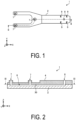
- FIG. 1 is a plan view illustrating an example of the ceramic structure 1 as the transfer arm.
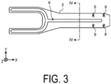
- FIG. 2 is a cross-sectional view taken along arrows II-II in FIG. 1 .
- FIG. 3 is a cross-sectional view taken along arrows III-III in FIG. 2 .
- the ceramic structure 1 as the transfer arm may have a Y-shape in a plan view.
- the ceramic structure 1 may include a linearly extending arm portion and a bifurcated holding portion provided at a tip end of the arm portion.
- the ceramic structure 1 may include a plurality of (three in the drawing) intake ports 7 at a base end portion and bifurcated tip end portions of the holding portion.
- the ceramic structure 1 may include an exhaust port 8 at a base end portion of the arm portion.
- the ceramic structure 1 may include a plurality of through holes 9 for connecting the ceramic structure 1 to a shaft or the like of a transfer device (not illustrated) with bolts.
- the ceramic structure 1 has the Y-shape in a plan view.
- the shape of the ceramic structure 1 is not limited to the Y-shape, and may be a rectangular shape, a circular shape, a trapezoidal shape, or other shape.
- the ceramic structure 1 includes three intake ports 7; however, the number of intake ports 7 is not limited to three.
- a channel 6 connecting to the plurality of intake ports 7 and the exhaust port 8 described above may be located inside the ceramic structure 1.
- a suction mechanism (not illustrated) connected to an opening portion of the exhaust port 8 is operated, by using an adsorption force generated at this time, the ceramic structure 1 can adsorb a sample.
- the ceramic structure 1 may include a first base 2 and a second base 4.
- a recessed portion 30 described later may be located on a surface of the first base 2.
- the recessed portion 30 may extend along a first direction (here, for example, the X-axis direction) and form a part of the channel 6.
- the second base 4 may include the plurality of intake ports 7 and the exhaust port 8 described above. The plurality of intake ports 7 and the exhaust port 8 may penetrate through the second base 4.
- the first base 2 and the second base 4 may contain a plurality of ceramic particles.
- the ceramic particles may be, for example, particles of silicon carbide (SiC). Examples of other ceramic particles include alumina, zirconia, and silicon nitride. When the ceramic particles are silicon carbide, the first base 2 and the second base 4 are suitable for electric discharge machining described later.
- the recessed portion 30 may include a first wall surface 31 (an example of an inner wall surface), a second wall surface 32 (an example of an inner wall surface) located to face the first wall surface 31, and a bottom surface 33.
- Porosity of the porous layer 5 may be 5 vol% or more and 20 vol% or less.
- the porosity described herein can be obtained from a cross-sectional photograph of the porous layer 5. An area ratio of pores in the porous layer 5 in the cross-sectional photograph is referred to as the porosity.
- a magnification of the cross-sectional photograph may be, for example, from 100 times to 10000 times.
- the magnification at the time of photographing may be set to such a magnification that a shape of the pore can be determined.
- a specific measurement of the porosity may be performed by importing a photograph taken into image analysis software, binarizing the photograph, and distinguishing the pores from the other portions.
- the porous layer 5 may be located on, for example, each of the first wall surface 31, the second wall surface 32, and the bottom surface 33.
- first porous layer 51 the porous layer 5 located on the first wall surface 31
- second porous layer 52 the porous layer 5 located on the second wall surface 32
- third porous layer 53 the porous layer 5 located on the bottom surface 33
- first thickness D1 an average value of the thicknesses of the first porous layer 51 and the second porous layer 52 is referred to as "first thickness D1".
- second thickness D2 a thickness of the third porous layer 53 is referred to as "second thickness D2".
- the second thickness D2 may be smaller than the first thickness D1.
- the first thickness D1 may be, for example, from 3 ⁇ m to 200 ⁇ m.
- the second thickness D2 may be smaller than the first thickness D1 and may be, for example, from 0 ⁇ m to 50 ⁇ m. As the first thickness D1 is greater, heat transfer via the first porous layer 51 is reduced.
- the first thickness D1 may be 3 ⁇ m or more.
- the first thickness D1 is preferably 10 ⁇ m or more, and 50 ⁇ m or more.
- the first thickness D1 may be 200 ⁇ m or less.
- the second thickness D2 may be 0 ⁇ m.
- the second thickness D2 is preferably 3 ⁇ m or less.
- the second thickness D2 may be 30% or less of the first thickness D1.
- the porous layer 5 includes the gaps, and thus the strength of the porous layer 5 is lower than that of the base portion 3.
- the bottom surface 33 of the recessed portion 30 is more likely to be a starting point of breakage compared to the first wall surface 31 and the second wall surface 32.
- the second thickness D2 is smaller than the first thickness D1, and thus the breakage which starts from the bottom surface 33 is less likely to occur compared to the case where the second thickness D2 is equal to the first thickness D1.
- the ceramic structure 1 according to the embodiment can reduce the heat transfer between the fluid flowing through the channel 6 and the first base 2 while maintaining the strength of the ceramic structure 1.
- the porous layer 5 may contain oxygen.
- oxygen in the porous layer 5 may be bonded to a metal element in the porous layer 5 to form an oxide.
- a content of oxygen in the porous layer 5 may be larger than a content of oxygen in the base portion 3. In this case, the porous layer 5 is less likely to be oxidized compared to the base portion 3, and thus is less likely to be altered.
- a large amount of oxygen may be distributed on a surface of the porous layer 5.
- the porous layer 5 may contain a metal phase.
- the metal phase may be, for example, silicon (Si).
- a content of the metal phase in the base portion 3 may be larger than a content of the metal phase in the porous layer 5.
- the base portion 3 has higher resistance to tensile stress compared to the porous layer 5, and separation or cracking is less likely to occur.
- first base 2 of the ceramic structure 1 Next, an example of a manufacturing method for the first base 2 of the ceramic structure 1 according to the embodiment will be described.
- green sheets are formed by a doctor blade method or a roll compaction method using raw material of the first base 2.
- a plurality of the green sheets are layered to obtain a layered body.
- the obtained layered body is fired to obtain a sintered body of the first base 2.
- the sintered body of the first base 2 is subjected to the electric discharge machining to form the recessed portion 30 in which the porous layer 5 is located on the surface portion.
- the sintered body of the first base 2 is subjected to the electric discharge machining to form the porous layer 5 on the first wall surface 31, the second wall surface 32, and the bottom surface 33 of the recessed portion 30.
- the sintered body of the first base 2 is subjected to blasting to remove a part of the porous layer 5 on the bottom surface 33, so that the first base 2 according to the embodiment can be obtained.
- the recessed portion 30 can also be produced by subjecting the sintered body of the first base 2 to grinding and blasting, then to the electric discharge machining, and further to the blasting.
- the method of obtaining the first base 2 is not limited to the method described above.
- the layered body may be subjected to machining to form the recessed portion 30, and then fired to obtain the first base 2.
- the porous layer 5 is not present on the surface of the recessed portion 30, and thus the surface of the recessed portion 30 may be subjected to the electric discharge machining to form the porous layer 50, and then the thickness of the porous layer 50 on the bottom surface 33 may be reduced by the blasting or other method.
- the formation of the recessed portion 30 by the electric discharge machining can be performed by using a commercially available electric discharge machine such that the sintered body of the first base 2 is immersed in a cooling machining liquid such as kerosene or deionized water, a high-frequency pulse voltage is applied to an engraving machining electrode to generate arc discharge between the electrode and the sintered body facing the electrode, and a portion to serve as the recessed portion 30 is melted and removed.
- the above-described machining electrode may be made of a copper-tungsten alloy, a silver-tungsten alloy, copper, brass, graphite, copper-graphite, or the like.
- Machining of the recessed portion 30 can be performed with high precision by spacing the electrode apart from a machining location to face the machining location with a distance of 1 ⁇ m to several tens of ⁇ ms and applying a no-load voltage from 90 V to 300 V.
- the blasting can be performed by masking a portion other than the recessed portion 30, then feeding an abrasive made of material such as glass, alumina, GC, or B 4 C into a commercially available blasting machine, and projecting the abrasive toward the bottom surface of the recessed portion 30.
- the ceramic structure (as an example, the ceramic structure 1) according to the embodiment includes the base (as an example, the first base 2) containing the plurality of ceramic particles.
- the base includes the base portion (as an example, the base portion 3) including the recessed portion (as an example, the recessed portion 30).
- the recessed portion includes the inner wall surfaces (as an example, the first wall surface 31 and the second wall surface 32) and the bottom surface (as an example, the bottom surface 33).
- the thickness of the porous layer 5 (the third porous layer 53) on the bottom surface 33 is smaller than the thickness of the porous layer 5 (the first porous layer 51 and the second porous layer 52) on the first wall surface 31 and the second wall surface 32.
- the porous layer 5 is thinner on the bottom surface 33, which has a high probability of becoming the starting point of breakage, compared to on the first wall surface 31 and the second wall surface 32.
- the breakage which starts from the bottom surface 33 is less likely to occur, and the strength can be maintained.
Landscapes
- Chemical & Material Sciences (AREA)
- Engineering & Computer Science (AREA)
- Ceramic Engineering (AREA)
- Materials Engineering (AREA)
- Structural Engineering (AREA)
- Organic Chemistry (AREA)
- Manufacturing & Machinery (AREA)
- Porous Artificial Stone Or Porous Ceramic Products (AREA)
Abstract
A ceramic structure according to the present disclosure includes a base containing a plurality of ceramic particles. The base includes a base portion including a recessed portion. The recessed portion includes an inner wall surface and a bottom surface. In the recessed portion, a porous layer is located at least on a surface portion of the inner wall surface, and when an average value of thicknesses of the porous layer on the inner wall surface is defined as a first thickness, and a thickness of the porous layer on the bottom surface is defined as a second thickness, the second thickness is smaller than the first thickness.
Description
- The present disclosure relates to a ceramic structure.
- Patent Document 1 discloses a ceramic transfer arm including an adsorption hole for adsorbing a transfer object such as a semiconductor wafer, a suction hole connected to a suction mechanism, and a suction path through which the adsorption hole and the suction hole communicate with each other.
- Patent Document 1:
JP 2018-125374 A - A ceramic structure according to one aspect of the present disclosure includes a base containing a plurality of ceramic particles. The base includes a base portion including a recessed portion. The recessed portion includes an inner wall surface and a bottom surface. In the recessed portion, a porous layer is located at least on a surface portion of the inner wall surface, and when an average value of thicknesses of the porous layer on the inner wall surface is defined as a first thickness, and a thickness of the porous layer on the bottom surface is defined as a second thickness, the second thickness is smaller than the first thickness.
- According to the present disclosure, for example, heat transfer between a fluid in a recessed portion and a base can be reduced, while a strength of the base is maintained.
-
-
FIG. 1 is a plan view illustrating an example of a ceramic structure as a transfer arm. -
FIG. 2 is a cross-sectional view taken along arrows II-II inFIG. 1 . -
FIG. 3 is a cross-sectional view taken along arrows III-III inFIG. 2 . -
FIG. 4 is a cross-sectional view taken along arrows IV-IV inFIG. 3 . -
FIG. 5 is a cross-sectional view of a first base of the ceramic structure according to another embodiment. - Modes (hereinafter, referred to as "embodiments") for implementing a ceramic structure according to the present disclosure will be described in detail below with reference to the accompanying drawings. Note that the present disclosure is not limited by the embodiments. Embodiments can be appropriately combined so as not to contradict each other in terms of processing content. In the following embodiments, the same portions are denoted by the same reference signs, and redundant explanations are omitted.
- In the following embodiments, expressions such as "constant", "orthogonal", "perpendicular", and "parallel" may be used, but these expressions need not mean exactly "constant", "orthogonal", "perpendicular", and "parallel". In other words, each of the expressions described above allows for deviations in, for example, manufacturing accuracy, or installation accuracy.
- In each of the drawings, which will be referred to below, for ease of explanation, an X axis direction, a Y axis direction, and a Z axis direction that are orthogonal to each other may be defined to illustrate a rectangular coordinate system in which a Z axis positive direction is a vertically upward direction. A rotation direction about the vertical axis as a rotation center may be referred to as a θ direction.
- Conventionally, a transfer arm has been used to transfer a sample such as a semiconductor wafer. Patent Document 1 discloses a transfer arm in which a body made of ceramics includes an adsorption hole for adsorbing a transfer object and a suction hole connected to a suction mechanism, and a suction path, through which the adsorption hole and the suction hole communicate with each other, is provided inside the body.
- A body of the transfer arm disclosed in Patent Document 1 is made of ceramics. Thus, the transfer arm has a high corrosion resistance and a high strength. However, in the transfer arm described in Patent Document 1, when the temperature of a fluid in the suction path is high, a thermal stress is generated in the body due to a temperature difference between the fluid and the body portion, and separation or cracking may occur.
- Thus, a technique for reducing the heat transfer between the fluid in the recessed portion and the base while maintaining the strength of the base is anticipated.
- Hereinafter, an example in which the ceramic structure according to the embodiment is applied to a transfer arm for transferring a sample such as a semiconductor wafer will be described. The ceramic structure according to the embodiment is applicable to other devices than the transfer arm. For example, the ceramic structure according to the embodiment may be applied to a shower plate that ejects heated process gas to the sample such as the semiconductor wafer. The shower plate in this case may include, for example, a disk-shaped base made of ceramics, a channel formed inside the base, and a resistance heating element buried in the base. Other than that, the ceramic structure according to the embodiment may be applied to, for example, a heat exchanger.
- First, a configuration of a ceramic structure 1 as a transfer arm will be described with reference to
FIGs. 1 to 3 .FIG. 1 is a plan view illustrating an example of the ceramic structure 1 as the transfer arm.FIG. 2 is a cross-sectional view taken along arrows II-II inFIG. 1 .FIG. 3 is a cross-sectional view taken along arrows III-III inFIG. 2 . - As illustrated in
FIG. 1 , the ceramic structure 1 as the transfer arm may have a Y-shape in a plan view. Specifically, the ceramic structure 1 may include a linearly extending arm portion and a bifurcated holding portion provided at a tip end of the arm portion. The ceramic structure 1 may include a plurality of (three in the drawing)intake ports 7 at a base end portion and bifurcated tip end portions of the holding portion. The ceramic structure 1 may include anexhaust port 8 at a base end portion of the arm portion. Further, the ceramic structure 1 may include a plurality of throughholes 9 for connecting the ceramic structure 1 to a shaft or the like of a transfer device (not illustrated) with bolts. - In the illustrated example, the ceramic structure 1 has the Y-shape in a plan view. However, the shape of the ceramic structure 1 is not limited to the Y-shape, and may be a rectangular shape, a circular shape, a trapezoidal shape, or other shape. In the illustrated example, the ceramic structure 1 includes three
intake ports 7; however, the number ofintake ports 7 is not limited to three. - As illustrated in
FIG. 2 , achannel 6 connecting to the plurality ofintake ports 7 and theexhaust port 8 described above may be located inside the ceramic structure 1. When a suction mechanism (not illustrated) connected to an opening portion of theexhaust port 8 is operated, by using an adsorption force generated at this time, the ceramic structure 1 can adsorb a sample. - The ceramic structure 1 may include a
first base 2 and a second base 4. A recessedportion 30 described later may be located on a surface of thefirst base 2. Therecessed portion 30 may extend along a first direction (here, for example, the X-axis direction) and form a part of thechannel 6. The second base 4 may include the plurality ofintake ports 7 and theexhaust port 8 described above. The plurality ofintake ports 7 and theexhaust port 8 may penetrate through the second base 4. - The second base 4 is located on the
first base 2 so as to close a surface of thefirst base 2 on which therecessed portion 30 is located. Thefirst base 2 and the second base 4 are bonded to each other via, for example, an adhesive. When thefirst base 2 and the second base 4 are bonded to each other, an opening portion of therecessed portion 30 is closed by the second base 4. This forms thechannel 6 described above. The second base 4 is an example of a cover portion. - The
first base 2 and the second base 4 may contain a plurality of ceramic particles. The ceramic particles may be, for example, particles of silicon carbide (SiC). Examples of other ceramic particles include alumina, zirconia, and silicon nitride. When the ceramic particles are silicon carbide, thefirst base 2 and the second base 4 are suitable for electric discharge machining described later. - The
first base 2 and the second base 4 may further contain a metal phase. The metal phase may be, for example, silicon (Si). When the metal phase is contained, thefirst base 2 and the second base 4 are suitable for the electric discharge machining even if the ceramic particles do not have electrical conductivity. When silicon carbide is used as the ceramic particles and Si is contained as the metal phase, thefirst base 2 and the second base 4 are particularly suitable for the electric discharge machining. In the case of a combination of silicon carbide and Si, silicon carbide may be from 60 vol% to 95 vol%, and Si may be from 5 vol% to 40 vol%. The base may be produced by preparing a powder compact by using raw materials having such a ratio and firing the powder compact at 1400°C to 1500°C in a non-oxidizing atmosphere. Thefirst base 2 and the second base 4 may further contain oxygen. The detailed configuration of thefirst base 2 will be described below with reference toFIG. 4 . - Next, a configuration of the
first base 2 of the ceramic structure 1 according to the embodiment will be described with reference toFIG. 4. FIG. 4 is a cross-sectional view taken along arrows IV-IV inFIG. 3 . As illustrated inFIG. 4 , thefirst base 2 may include abase portion 3 including the recessedportion 30 and aporous layer 5 located on a surface of the recessedportion 30. - The recessed
portion 30 may include a first wall surface 31 (an example of an inner wall surface), a second wall surface 32 (an example of an inner wall surface) located to face thefirst wall surface 31, and abottom surface 33. - The
base portion 3 may be dense. Theporous layer 5 includes gaps. The gap is a region where the ceramic particles and the metal phase are not present in theporous layer 5. The amount of gaps in theporous layer 5 may be larger than that in thebase portion 3. When thebase portion 3 includes voids, the size of the gap may be larger than the size of the void in thebase portion 3. The size of the gap may be from 0.5 µm to 50 µm in terms of equivalent circle diameter. When the size of the gap is large, the coefficient of thermal conductivity of theporous layer 5 is small. When the size of the gap is small, the strength of theporous layer 5 is less degraded. When the size of the gap is from about 3 µm to 20 µm, the thermal conduction and the strength are well-balanced. Note that the sizes of the gap and the void described below are equivalent circle diameters. Porosity of theporous layer 5 may be 5 vol% or more and 20 vol% or less. When theporous layer 5 is located on a surface portion of the recessedportion 30, heat transfer between a fluid (for example, gas) flowing through thechannel 6 and thefirst base 2 can be reduced. The porosity described herein can be obtained from a cross-sectional photograph of theporous layer 5. An area ratio of pores in theporous layer 5 in the cross-sectional photograph is referred to as the porosity. A magnification of the cross-sectional photograph may be, for example, from 100 times to 10000 times. The magnification at the time of photographing may be set to such a magnification that a shape of the pore can be determined. A specific measurement of the porosity may be performed by importing a photograph taken into image analysis software, binarizing the photograph, and distinguishing the pores from the other portions. - The
porous layer 5 may be located on, for example, each of thefirst wall surface 31, thesecond wall surface 32, and thebottom surface 33. Hereinafter, theporous layer 5 located on thefirst wall surface 31 is referred to as "firstporous layer 51", theporous layer 5 located on thesecond wall surface 32 is referred to as "secondporous layer 52", and theporous layer 5 located on thebottom surface 33 is referred to as "thirdporous layer 53". - Here, an average value of the thicknesses of the first
porous layer 51 and the secondporous layer 52 is referred to as "first thickness D1". In addition, a thickness of the thirdporous layer 53 is referred to as "second thickness D2". In this case, the second thickness D2 may be smaller than the first thickness D1. The first thickness D1 may be, for example, from 3 µm to 200 µm. The second thickness D2 may be smaller than the first thickness D1 and may be, for example, from 0 µm to 50 µm. As the first thickness D1 is greater, heat transfer via the firstporous layer 51 is reduced. The first thickness D1 may be 3 µm or more. In particular, the first thickness D1 is preferably 10 µm or more, and 50 µm or more. The first thickness D1 may be 200 µm or less. The second thickness D2 may be 0 µm. In particular, the second thickness D2 is preferably 3 µm or less. For example, the second thickness D2 may be 30% or less of the first thickness D1. - The
porous layer 5 includes the gaps, and thus the strength of theporous layer 5 is lower than that of thebase portion 3. In addition, thebottom surface 33 of the recessedportion 30 is more likely to be a starting point of breakage compared to thefirst wall surface 31 and thesecond wall surface 32. On the other hand, in the ceramic structure 1 according to the embodiment, the second thickness D2 is smaller than the first thickness D1, and thus the breakage which starts from thebottom surface 33 is less likely to occur compared to the case where the second thickness D2 is equal to the first thickness D1. Thus, the ceramic structure 1 according to the embodiment can reduce the heat transfer between the fluid flowing through thechannel 6 and thefirst base 2 while maintaining the strength of the ceramic structure 1. - The
porous layer 5 may contain oxygen. For example, oxygen in theporous layer 5 may be bonded to a metal element in theporous layer 5 to form an oxide. A content of oxygen in theporous layer 5 may be larger than a content of oxygen in thebase portion 3. In this case, theporous layer 5 is less likely to be oxidized compared to thebase portion 3, and thus is less likely to be altered. A large amount of oxygen may be distributed on a surface of theporous layer 5. - The
porous layer 5 may contain a metal phase. The metal phase may be, for example, silicon (Si). A content of the metal phase in thebase portion 3 may be larger than a content of the metal phase in theporous layer 5. In this case, thebase portion 3 has higher resistance to tensile stress compared to theporous layer 5, and separation or cracking is less likely to occur. - Next, an example of a manufacturing method for the
first base 2 of the ceramic structure 1 according to the embodiment will be described. First, green sheets are formed by a doctor blade method or a roll compaction method using raw material of thefirst base 2. Then, a plurality of the green sheets are layered to obtain a layered body. Subsequently, the obtained layered body is fired to obtain a sintered body of thefirst base 2. - Subsequently, the sintered body of the
first base 2 is subjected to the electric discharge machining to form the recessedportion 30 in which theporous layer 5 is located on the surface portion. For example, the sintered body of thefirst base 2 is subjected to the electric discharge machining to form theporous layer 5 on thefirst wall surface 31, thesecond wall surface 32, and thebottom surface 33 of the recessedportion 30. Thereafter, the sintered body of thefirst base 2 is subjected to blasting to remove a part of theporous layer 5 on thebottom surface 33, so that thefirst base 2 according to the embodiment can be obtained. The recessedportion 30 can also be produced by subjecting the sintered body of thefirst base 2 to grinding and blasting, then to the electric discharge machining, and further to the blasting. - Note that the method of obtaining the
first base 2 is not limited to the method described above. For example, the layered body may be subjected to machining to form the recessedportion 30, and then fired to obtain thefirst base 2. In this case, theporous layer 5 is not present on the surface of the recessedportion 30, and thus the surface of the recessedportion 30 may be subjected to the electric discharge machining to form the porous layer 50, and then the thickness of the porous layer 50 on thebottom surface 33 may be reduced by the blasting or other method. - The formation of the recessed
portion 30 by the electric discharge machining can be performed by using a commercially available electric discharge machine such that the sintered body of thefirst base 2 is immersed in a cooling machining liquid such as kerosene or deionized water, a high-frequency pulse voltage is applied to an engraving machining electrode to generate arc discharge between the electrode and the sintered body facing the electrode, and a portion to serve as the recessedportion 30 is melted and removed. The above-described machining electrode may be made of a copper-tungsten alloy, a silver-tungsten alloy, copper, brass, graphite, copper-graphite, or the like. Machining of the recessedportion 30 can be performed with high precision by spacing the electrode apart from a machining location to face the machining location with a distance of 1 µm to several tens of µms and applying a no-load voltage from 90 V to 300 V. The blasting can be performed by masking a portion other than the recessedportion 30, then feeding an abrasive made of material such as glass, alumina, GC, or B4C into a commercially available blasting machine, and projecting the abrasive toward the bottom surface of the recessedportion 30. - As described above, the ceramic structure (as an example, the ceramic structure 1) according to the embodiment includes the base (as an example, the first base 2) containing the plurality of ceramic particles. The base includes the base portion (as an example, the base portion 3) including the recessed portion (as an example, the recessed portion 30). The recessed portion includes the inner wall surfaces (as an example, the
first wall surface 31 and the second wall surface 32) and the bottom surface (as an example, the bottom surface 33). In the recessed portion, the porous layer (as an example, the firstporous layer 51 and the second porous layer 52) is located at least on the surface portion of the inner wall surface, and when the average value of the thicknesses of the porous layer on the inner wall surface is defined as a first thickness, and a thickness of the porous layer on the bottom surface is defined as a second thickness, the second thickness is smaller than the first thickness. - In the ceramic structure 1 according to the embodiment, the
porous layer 5 is located at least on the surface portions of thefirst wall surface 31 and thesecond wall surface 32, and thus heat transfer between the fluid (for example, gas) flowing through the channel and the base can be reduced. - In the ceramic structure 1 according to the embodiment, the thickness of the porous layer 5 (the third porous layer 53) on the
bottom surface 33 is smaller than the thickness of the porous layer 5 (the firstporous layer 51 and the second porous layer 52) on thefirst wall surface 31 and thesecond wall surface 32. According to such a configuration, theporous layer 5 is thinner on thebottom surface 33, which has a high probability of becoming the starting point of breakage, compared to on thefirst wall surface 31 and thesecond wall surface 32. Thus, the breakage which starts from thebottom surface 33 is less likely to occur, and the strength can be maintained. - Thus, the ceramic structure 1 according to the embodiment can reduce the heat transfer between the fluid in the recessed
portion 30 and the base, while maintaining the strength of the ceramic structure 1. - In the embodiment described above, the example has been described with reference to
FIG. 4 in which the second thickness D2 is smaller than the first thickness D1. The second thickness D2 is not limited to the example ofFIG. 4 . The second thickness D2 may be 0% of the first thickness D1. That is, theporous layer 5 may not be located on thebottom surface 33. -
FIG. 5 is a cross-sectional view of thefirst base 2 of the ceramic structure 1 according to another embodiment. As illustrated inFIG. 5 , the ceramic structure 1 according to the embodiment may include the porous layer 5 (the firstporous layer 51 and the second porous layer 52) on the surface portions of thefirst wall surface 31 and thesecond wall surface 32, and need not include the porous layer 5 (the third porous layer 53) on thebottom surface 33. According to such a configuration, the breakage which starts from thebottom surface 33 is less likely to occur compared to a case where theporous layer 5 is present on thebottom surface 33, and the strength can be maintained. - Note that the embodiments disclosed herein are exemplary in all respects and not restrictive. The aforementioned embodiments can be embodied in a variety of forms. The above-described embodiments may be omitted, substituted or modified in various forms without departing from the scope and spirit of the appended claims.
-
- 1 Ceramic structure
- 2 First base
- 3 Base portion
- 5 Porous layer
- 30 Recessed portion
- 31 First wall surface (example of inner wall surface)
- 32 Second wall surface (example of inner wall surface)
- 33 Bottom surface
- 51 First porous layer
- 52 Second porous layer
- 53 Third porous layer
Claims (8)
- A ceramic structure comprising:a base containing a plurality of ceramic particles, whereinthe base comprises a base portion comprising a recessed portion,the recessed portion comprises an inner wall surface and a bottom surface,a porous layer is located at least on a surface portion of the inner wall surface, andwhen an average value of thicknesses of the porous layer on the inner wall surface is defined as a first thickness, and a thickness of the porous layer on the bottom surface is defined as a second thickness, the second thickness is smaller than the first thickness.
- The ceramic structure according to claim 1, wherein porosity of the porous layer is 5 vol% or more and 20 vol% or less.
- The ceramic structure according to claim 1, whereinthe first thickness is 10 µm or more, andthe second thickness is 3 µm or less.
- The ceramic structure according to claim 1, whereinthe base contains a metal phase, anda content of the metal phase in the base portion is larger than a content of the metal phase in the porous layer.
- The ceramic structure according to claim 1, whereinthe base contains oxygen, anda content of oxygen in the porous layer is larger than a content of oxygen in the base portion.
- The ceramic structure according to claim 4, whereinthe ceramic particles are SiC particles, andthe metal phase is Si.
- The ceramic structure according to claim 1, wherein the recessed portion is a channel extending in a first direction.
- The ceramic structure according to claim 1, further comprising a cover portion covering the recessed portion.
Applications Claiming Priority (2)
| Application Number | Priority Date | Filing Date | Title |
|---|---|---|---|
| JP2022138731 | 2022-08-31 | ||
| PCT/JP2023/031528 WO2024048651A1 (en) | 2022-08-31 | 2023-08-30 | Ceramic structure |
Publications (1)
| Publication Number | Publication Date |
|---|---|
| EP4583155A1 true EP4583155A1 (en) | 2025-07-09 |
Family
ID=90099710
Family Applications (1)
| Application Number | Title | Priority Date | Filing Date |
|---|---|---|---|
| EP23860413.6A Pending EP4583155A1 (en) | 2022-08-31 | 2023-08-30 | Ceramic structure |
Country Status (3)
| Country | Link |
|---|---|
| EP (1) | EP4583155A1 (en) |
| JP (1) | JPWO2024048651A1 (en) |
| WO (1) | WO2024048651A1 (en) |
Family Cites Families (4)
| Publication number | Priority date | Publication date | Assignee | Title |
|---|---|---|---|---|
| JP4413667B2 (en) * | 2004-03-19 | 2010-02-10 | 日本特殊陶業株式会社 | Electrostatic chuck |
| WO2013051713A1 (en) * | 2011-10-05 | 2013-04-11 | 京セラ株式会社 | Specimen holder |
| JP6640764B2 (en) | 2017-01-31 | 2020-02-05 | 京セラ株式会社 | Transfer arm, substrate transfer device and substrate processing device |
| JP2021004668A (en) * | 2019-06-27 | 2021-01-14 | 京セラ株式会社 | Passage member |
-
2023
- 2023-08-30 WO PCT/JP2023/031528 patent/WO2024048651A1/en not_active Ceased
- 2023-08-30 EP EP23860413.6A patent/EP4583155A1/en active Pending
- 2023-08-30 JP JP2024544329A patent/JPWO2024048651A1/ja active Pending
Also Published As
| Publication number | Publication date |
|---|---|
| JPWO2024048651A1 (en) | 2024-03-07 |
| WO2024048651A1 (en) | 2024-03-07 |
Similar Documents
| Publication | Publication Date | Title |
|---|---|---|
| KR102502299B1 (en) | electrostatic chuck | |
| JP4013386B2 (en) | Support for manufacturing semiconductor and method for manufacturing the same | |
| JP5154871B2 (en) | Electrostatic chuck and manufacturing method thereof | |
| US20080305005A1 (en) | Composite Ceramic Body and Manufacturing Method Thereof, Microchemical Chip, and Reformer | |
| KR20020092967A (en) | Ceramic substrate and its production method | |
| US6872908B2 (en) | Susceptor with built-in electrode and manufacturing method therefor | |
| JP2002160974A (en) | Aluminium nitride sintered compact and its manufacturing method, ceramic substrate and its manufacturing method | |
| KR100553444B1 (en) | Susceptors and the methods of manufacturing them | |
| JP2023021622A (en) | Electrostatic chuck and substrate fixing device | |
| JP2010042967A (en) | Ceramic member, method for manufacturing the same, and electrostatic chuck | |
| JP2022530320A (en) | High-density corrosion-resistant layer arrangement for electrostatic chuck | |
| KR20070113959A (en) | Electrostatic adsorption device | |
| JP2001308165A (en) | Susceptor and its manufacturing method | |
| JP2005150370A (en) | Electrostatic chuck | |
| EP4583155A1 (en) | Ceramic structure | |
| JP3966201B2 (en) | Wafer holder for semiconductor manufacturing apparatus and semiconductor manufacturing apparatus equipped with the same | |
| WO2012163268A1 (en) | Method for manufacturing ion optical device | |
| US20230303457A1 (en) | Joined body, holding device, and electrostatic chuck | |
| JP3810341B2 (en) | Electrostatic chuck | |
| JP2005072286A (en) | Electrostatic chuck | |
| JP6444078B2 (en) | Electrode embedded body | |
| JP2001319967A (en) | Method for manufacturing ceramic substrate | |
| JP2002170871A (en) | Electrostatic chuck | |
| JP2002110773A (en) | Electrostatic chuck | |
| JP7781314B1 (en) | Semiconductor manufacturing equipment components |
Legal Events
| Date | Code | Title | Description |
|---|---|---|---|
| STAA | Information on the status of an ep patent application or granted ep patent |
Free format text: STATUS: THE INTERNATIONAL PUBLICATION HAS BEEN MADE |
|
| PUAI | Public reference made under article 153(3) epc to a published international application that has entered the european phase |
Free format text: ORIGINAL CODE: 0009012 |
|
| STAA | Information on the status of an ep patent application or granted ep patent |
Free format text: STATUS: REQUEST FOR EXAMINATION WAS MADE |
|
| 17P | Request for examination filed |
Effective date: 20250219 |
|
| AK | Designated contracting states |
Kind code of ref document: A1 Designated state(s): AL AT BE BG CH CY CZ DE DK EE ES FI FR GB GR HR HU IE IS IT LI LT LU LV MC ME MK MT NL NO PL PT RO RS SE SI SK SM TR |
|
| DAV | Request for validation of the european patent (deleted) | ||
| DAX | Request for extension of the european patent (deleted) |