EP4583137A1 - Switching apparatus - Google Patents
Switching apparatus Download PDFInfo
- Publication number
- EP4583137A1 EP4583137A1 EP24307127.1A EP24307127A EP4583137A1 EP 4583137 A1 EP4583137 A1 EP 4583137A1 EP 24307127 A EP24307127 A EP 24307127A EP 4583137 A1 EP4583137 A1 EP 4583137A1
- Authority
- EP
- European Patent Office
- Prior art keywords
- main shaft
- positioning
- switching apparatus
- breaking
- positioning part
- Prior art date
- Legal status (The legal status is an assumption and is not a legal conclusion. Google has not performed a legal analysis and makes no representation as to the accuracy of the status listed.)
- Pending
Links
Images

Classifications
-
- H—ELECTRICITY
- H01—ELECTRIC ELEMENTS
- H01H—ELECTRIC SWITCHES; RELAYS; SELECTORS; EMERGENCY PROTECTIVE DEVICES
- H01H19/00—Switches operated by an operating part which is rotatable about a longitudinal axis thereof and which is acted upon directly by a solid body external to the switch, e.g. by a hand
- H01H19/36—Switches operated by an operating part which is rotatable about a longitudinal axis thereof and which is acted upon directly by a solid body external to the switch, e.g. by a hand the operating part having only two operative positions, e.g. relatively displaced by 180 degrees
- H01H19/38—Change-over switches
-
- H—ELECTRICITY
- H01—ELECTRIC ELEMENTS
- H01H—ELECTRIC SWITCHES; RELAYS; SELECTORS; EMERGENCY PROTECTIVE DEVICES
- H01H71/00—Details of the protective switches or relays covered by groups H01H73/00 - H01H83/00
- H01H71/02—Housings; Casings; Bases; Mountings
- H01H71/0207—Mounting or assembling the different parts of the circuit breaker
-
- H—ELECTRICITY
- H01—ELECTRIC ELEMENTS
- H01H—ELECTRIC SWITCHES; RELAYS; SELECTORS; EMERGENCY PROTECTIVE DEVICES
- H01H2300/00—Orthogonal indexing scheme relating to electric switches, relays, selectors or emergency protective devices covered by H01H
- H01H2300/018—Application transfer; between utility and emergency power supply
Definitions
- Example embodiments of the present disclosure relate generally to the field of electrical, and in particular to a switching apparatus.
- switches need to have higher durability and reliability.
- the switch operation load increases, placing higher requirements on the switch's mechanical and electrical performance.
- the actuation assemblies of the switch need to withstand long-term and high-load usage while maintaining stable switch performance and reliable operation.
- traditional switches under high-load conditions require periodic maintenance and inspection of the actuating components to improve their reliability and service life. Since the actuation assemblies of the conventional switch are difficult to be assembled and disassembled, maintenance personnel need more time and resources to perform maintenance work.
- the object of the present disclosure is to provide a switching apparatus to at least partially address the above-described and/or other potential problems with conventional switching apparatus.
- a switching apparatus in a first aspect of the present disclosure, includes a breaking assembly comprising a main shaft and a transmission component arranged along a direction A of the main shaft and at least one breaking unit (1104), wherein the transmission component includes a positioning bracket with a first positioning part and a motive power input portion located on one side of the breaking assembly in a radial direction B; an actuation assembly, comprising a second positioning part detachably coupled to the first positioning part and a motive power output portion coupled to the motive power input portion, wherein the actuation assembly is arranged to drive a movable contact of the at least one breaking unit to rotate around the main shaft between an open position and a closed position via coupling between the motive power input portion and the motive power output portion; and a middle cover coupled to the breaking assembly and arranged between the breaking assembly and the actuation assembly, and comprising an opening portion adapted for one of the motive power input portion and the motive power output portion to pass through and an auxiliary positioning part, wherein the auxiliary positioning part is coupled
- the detachable coupling between the breaking assembly and the actuation assembly is achieved by the coupling between the first positioning part and the second positioning part.
- the actuation assembly transmits the power of the motive power output portion to the motive power input portion of the breaking assembly via the transmission component, driving the movable contact of the breaking assembly to rotate between the open position and the closed position.
- the opening portion of the middle cover may facilitate the passage of the motive power output portion and the motive power input portion, and may provide additional positioning bracket in the direction of the main shaft by the auxiliary positioning part.
- the detachably coupling of the first positioning part and the second positioning part facilitates the maintenance and repair work of the actuation assembly, and improving the performance and reliability of the switching apparatus.
- the first positioning part is located on outside of the breaking assembly in the radial direction B, and includes at least two first positioning holes respectively arranged at both ends of the positioning bracket along a width direction C of the middle cover perpendicular to the direction A of the main shaft.
- the actuation assembly includes a pair of positioning side plates spaced apart by a predetermined distance along the direction A of the main shaft, and the second positioning part includes at least two pairs of second positioning holes respectively arranged on the pair of positioning side plates, wherein the at least two first positioning holes are respectively located between the at least two pairs of second positioning holes and aligned to each other along the direction A of the main shaft; and at least two positioning pins respectively passing through the at least two second positioning holes and the at least two first positioning holes.
- the auxiliary positioning part includes at least two pairs of shaft hole portions, respectively arranged between the at least two pairs of second positioning holes and the at least two first positioning holes in the direction A of the main shaft, and comprising shaft holes for the positioning pins to pass through.
- the at least one breaking unit includes a plurality of breaking units distributed on both sides of the transmission component along the direction A of the main shaft.
- the plurality of breaking units are distributed on both sides of the transmission component along the direction A of the main shaft in equal numbers.
- the motive power input portion and the motive power output portion comprise gears engaged with each other.
- the switching apparatus further includes a control component arranged in parallel with the actuation assembly on an outer side of the middle cover away from the breaking assembly.
- the switching apparatus further includes a front cover coupled to the middle cover and covering the control component and the actuation assembly.
- the main shaft includes a plurality of main shaft segments respectively arranged in the at least one breaking unit and the transmission component, wherein each main shaft segment includes a first coupling portion and a second coupling portion at both axial ends, the first coupling portion is adapted to couple with the second coupling portion of an adjacent main shaft segment to transmit motive power.
- the switching apparatus further includes a pair of end plates respectively arranged at both ends of the breaking assembly in the direction A of the main shaft.
- the switching apparatus at least includes a dual power transfer switch.
- the term “comprise” and similar terms should be interpreted as open inclusion, that is, “including but not limited to”.
- the term “based on” should be interpreted as “based at least in part on”.
- the term “an embodiment” or “the embodiment” should be interpreted as “at least one embodiment”.
- the term “some embodiments” should be interpreted as “at least some embodiments”.
- Other explicit and implicit definitions may also be included below.
- the terms “first”, “second”, etc. may refer to different or identical objects. Other explicit and implicit definitions may also be included below.
- dual power transfer switches need the ability to connect and withstand short circuit currents.
- the switch while ensuring that the switch can withstand the shock of the short-circuit current when connected, while being able to reliably interrupt when the circuit is opened.
- the mechanical structure and the connecting parts of the switch need to have sufficient strength and stability to withstand current shocks and to provide a reliable electrical connection.
- the actuation assemblies are located on one side of the breaking assembly, or two sets of actuation assemblies are distributed on both sides of the breaking assembly.
- the performance requirement of the dual power transfer switch also become increasingly higher. For example, at a current level of 1600 A, the energy required for the disconnecting component is relatively higher, and the impact on each component is also more intense. Therefore, regular on-site maintenance and overhaul of each component are required. More on-site maintenance and overhaul efforts tend to be focused on the actuation assembly.
- the actuation assembly is typically difficult to disassemble and assemble, this makes on-site maintenance work extremely challenging.
- embodiments of the present disclosure provide a switching apparatus scheme.
- the breaking assembly, the actuation assembly and the middle cover of the switching apparatus cooperate together, which can enhance the reliability of a product and facilitate on-site maintenance.
- the transmission component of the breaking assembly is arranged along the direction of the main shaft and connected to the main shaft to achieve energy transmission and rotation functions.
- the positioning bracket of the breaking assembly is provided with a first positioning part for positioning and supporting to ensure the correct position of the transmission component and the actuation assembly.
- the actuation assembly By detachably coupling the second positioning part of the actuation assembly and the first positioning part, the actuation assembly can be conveniently connected or detached to facilitate on-site maintenance and repair of the actuation assembly.
- the coupling between the motive power input portion and the motive power output portion enables the actuation assembly to transmit a driving force to the breaking unit of the breaking assembly, so that the actuation assembly can effectively drive the movable contact of the breaking unit to rotate between the open position and a closed position.
- the middle cover may allow the motive power output portion to pass through the opening portion and form a coupling with the motive power input portion to achieve an energy transmission and a driving effect, to ensure a good physical connection and coupling.
- the auxiliary positioning part is coupled between the first positioning part and the second positioning part in the direction of the main shaft, which can provide additional positioning bracket in the direction of the main shaft, and ensure accurate positioning and stability between the separation assembly and the actuation assembly.
- the switching apparatus 100 such as a dual power transfer switch according to embodiments of the present disclosure are used to realize switching and changeover between two power supplies.
- the dual power transfer switch includes a mechanical or electronic component and has the function of automatic or manual operation.
- the dual power transfer switch is used for switching a load from one power supply to another power supply during a fault or maintenance period of one power supply to ensure continuous power supply of the load.
- the dual power transfer switch In a normal working state, the dual power transfer switch connects the load to one power supply.
- the switching apparatus 100 detects a change in a power supply state and switches the load from one power supply to another by operating the dual power transfer switch to avoid interruption or damage to the load. Therefore, by using the dual power transfer switch, the switching apparatus 100 can implement redundancy and switching of the power supply and provide reliable power supply of the dual power supply.
- the switching apparatus 100 provided according to embodiments of the present disclosure generally include a breaking assembly 110, an actuation assembly 120, and a middle cover 130.
- the actuation assembly 120 is detachably coupled to the breaking assembly 110 through the middle cover 130, and the actuation assembly 120 is controlled by the control component 140 to drive the breaking assembly 110 to execute an action of switching a power supply or shutting off the power supply.
- the breaking assembly 110 includes a main shaft 1101, a transmission component 1102, and at least one breaking unit 1104.
- the main shaft 1101 provides support and power transmission functions.
- the transmission component 1102 is located on the main shaft 1101 and arranged in the direction A of main shaft.
- the actuation assembly 120 includes a second positioning part 12011 and a motive power output portion 12013.
- the second positioning part 12011 is detachably coupled to the first positioning part 11022
- the motive power output portion 12013 is coupled to the motive power input portion 11023.
- the actuation assembly 120 is arranged to achieve driving a movable contact of the at least one breaking unit 1104 to rotate around the main shaft 1101 between an open position and a closed position via coupling between the motive power input portion 11023 and the motive power output portion 12013.
- the motive power input portion 11023 and the motive power output portion 12013 may transmit power and effect mechanical movement by way of intermeshed gearing or linkage connections.
- the gear is used to transmit force and rotational movement, and the connecting rod can achieve transmission of force and movement conversion. The selection of this in embodiments of the present disclosure depends on specific requirements and application scenarios.
- the actuation assembly 120 By detachably coupling the second positioning part 12011 and the first positioning part 11022, the actuation assembly 120 can be conveniently connected or detached.
- the coupling of the power output portion 12013 and the power input portion 11023 enables the actuation assembly 120 to transmit the driving force to the breaking unit 1104.
- the actuation assembly 120 can effectively drive the movable contact to rotate between the open position and the closed position, thereby providing an efficient and reliable switch operation, and ensuring the stability and maintainability of the apparatus.
- middle cover 130 is coupled to the breaking assembly 110 and arranged between the breaking assembly 110 and the actuation assembly 120.
- the middle cover 130 includes an opening portion 1301 and an auxiliary positioning part 1302.
- the opening portion 1301 is arranged to allow at least one of the motive power input portion 11023 and the motive power output portion 12013 to pass therethrough and to be coupled with each other, thereby realizing energy transmission and a driving effect.
- the opening portion 1301 can secure good physical connection and coupling.
- the auxiliary positioning part 1302 is coupled between the first positioning part 11022 and the second positioning part 12011 in the direction A of the main shaft. Such an arrangement provides additional positioning support to ensure accurate positioning and stability between the actuation assembly 120 and the breaking assembly 110.
- the opening portion 1301 and the auxiliary positioning part 1302 of the middle cover 130 enable the motive power input portion 11023 and the motive power output portion 12013 to pass through and be effectively coupled, thereby ensuring the reliability, stability and good positioning support of the switching apparatus 100.
- the actuation assembly 120 is detachably coupled to the breaking assembly 110, making on-site maintenance easier.
- At least one breaking unit 1104 includes a plurality of breaking units 1104.
- the plurality of breaking units 1104 are distributed at both sides of the transmission component 1102 along the direction A of the main shaft.
- Each breaking unit 1104 has an independent function and operation mechanism and they can work at the same time according to specific requirements and application scenarios.
- the plurality of breaking units 1104 are distributed on both sides of the transmission component 1102 along the direction A of the main shaft in equal numbers.
- the transmission component 1102 By distributing the plurality of breaking units 1104 on both sides of the transmission component 1102 in the equal number, a more uniform force distribution and breaking effect may be achieved.
- This layout may also increase the stability and the balance of the transmission component 1102. Since the number and positions of the division units 1104 are the same, the transmission component 1102 can maintain balanced force distribution during working, thereby reducing uneven load and vibration, and improving the reliability of the transmission component 1102.
- the distribution manner can also achieve symmetrical force distribution, reduce the load and wear of the transmission component 1102, and prolong the service life thereof.
- the first positioning part 11022 of the transmission component 1102 is located outward of the breaking assembly 110 in the radial direction B to ensure accurate positioning and stability of the breaking assembly 110 during operation.
- the first positioning part 11022 includes at least two first positioning holes 11024 which are respectively disposed at both ends of the positioning bracket 11021 along the width direction C of the middle cover 130 and perpendicular to the direction A of the main shaft.
- the actuation assembly 120 includes a pair of positioning side plates 1201 spaced apart a predetermined distance in the direction A of the main shaft.
- the second positioning part 12011 includes at least two pairs of second positioning holes 12012 and at least two positioning pins 1202.
- the at least two second positioning holes 12012 are arranged on the pair of side plates 1201 respectively, and the at least two first positioning holes 11024 are located between the at least two pairs of second positioning holes 12012 respectively, and aligned in the direction A of the main shaft to ensure the positioning accuracy and reliability.
- the at least two positioning pins 1202 pass through the at least two second positioning holes 1212 and the at least two first positioning holes 11024.
- the actuation assembly 120 is stably positioned and connected to ensure the correct positioning and alignment of the actuation assembly 120 in the switching apparatus 100 to realize accurate operation and reliable functions.
- the combination of the second positioning hole 12012, the first positioning hole 11024 and the positioning pin 1202 enables the executing assembly 120 to be limited in the switching apparatus 100 perpendicular to the direction A of the main shaft, and maintain a stable and reliable position.
- the locating pin 1202 may be a snap spring locating pin 1202.
- the auxiliary positioning part 1302 of the middle cover 130 includes at least two pairs of shaft hole portions.
- the at least two pairs of shaft hole portions are respectively arranged between the at least two pairs of second positioning holes 12012 and the at least two first positioning holes 11024 in the direction A of main shaft.
- Each pair of shaft hole portions includes a shaft hole through which the positioning pin 1202 passes.
- the shaft hole portion of the auxiliary positioning part 1302 is used to increase the positioning precision and reliability. They provide additional support and positioning points to ensure that the first positioning part 11022 and the second positioning part 12011 maintain stable and accurate positioning during operation, thereby ensuring the accurate operation and reliability functions of the switching apparatus 100.
- the auxiliary positioning part 1302 includes a first segment 13021 and a second segment 13022 in the direction A of main shaft.
- the first positioning part 11022 passes through the penetrating portion 1303 of the middle cover 130, the first positioning part 11022 is located between the first segment 13021 and the second segment 13022.
- the first segment 13021 and the second segment 13022 are respectively coupled between the first positioning part 11022 and the second positioning part 12011.
- the main shaft 1101 is used to transmit power and effect rotation, in some cases, the main shaft 1101 comprises a plurality of main shaft segments arranged in at least one of the breaking unit 1104 and the transmission component 1102.
- Each of the main shaft segments includes a first coupling portion and a second coupling portion located at both ends of the shaft direction, and the two coupling portions are located at both respective ends of the main shaft segment to achieve coupling and power transmission between the main shaft segments.
- the first coupling portion matches the second coupling portion of the adjacent main shaft segment to achieve the coupling connection.
- Such a coupling connection can effectively transfer power, so that the main shaft segments can work in cooperation to jointly complete a required movement task.
- each of the main shaft segments can be interconnected to form an integral main shaft system for greater power output and more complex motion control. In this way, more flexible and efficient power transmission can be achieved, satisfying complex movement requirements.
- control component 140 described above continues to be arranged in parallel with the actuation assembly 120 on the outside of the middle cover 130 away from the breaking assembly 110 in order to facilitate the arrangement and operation of the control component 140.
- control section 140 includes a controller.
- the control component 140 of the switching apparatus 100 collects and monitors the state of the power supply in real time to ensure that the load obtains a reliable power supply.
- the switching apparatus 100 includes a power supply end 1103 and a load end 140.
- the power supply end 1103 includes a first power supply 11031 and a second power supply 11032 that provide power supply.
- the load end 140 may be coupled to multiple loads.
- control component 140 is connected to a power supply through a sampling line and collects state information about the power supply in real time.
- the state information includes parameters such as a voltage, a current, and a frequency of a power supply.
- the control component 140 can know a current working state of the power supply and determine whether the power supply is normal or faulty.
- the control component 140 monitors that the power supply state is abnormal, for example, the voltage is excessively high or low, and the frequency is unstable, the control component 140 sends a relevant instruction according to the monitored power supply state information.
- the switching apparatus 100 will drive the switching apparatus 100 to switch between the first power supply 11031 and the second power supply 11032 to provide a reliable power supply for the load.
- This switching operation can ensure that when the first power supply 11031 fails, the second power supply 11032 can take over immediately and continue supply power to the load, thereby ensuring the continuity and reliability of the system.
- the first power supply 11031 can include a primary power supply that provides power to the switching apparatus 100 through a power grid (e. g., mains electricity) or other external power supply.
- the second power supply 11032 may be a battery, a generator, or other reliable backup power device.
- the switching apparatus 100 also includes a front cover 150 and a pair of end plates 160.
- the front cover 150 serves as protection and packaging in the switching apparatus 100.
- the front cover 150 is coupled with the middle cover 130 and covers the control component 140 and the actuation assembly 120.
- the front cover 150 is generally required to be considered easy to operate and maintain, so that the user can conveniently access the control member 140 and the actuation assembly 120 and perform necessary operation and maintenance.
- the pair of end plates 160 are respectively arranged at both ends of the breaking assembly 110 in the direction A of main shaft, and used for supporting and fixing to ensure stability and reliability of the switching apparatus 100.
- breaking assembly 110 is well supported and remains stable during operation. This helps to accurately realize the open position and closed position operation and ensure the normal operation of the switching apparatus 100.
- the end plate 160 may also provide additional safety protection. They may prevent the breaking assemblies 110 from breaking away or accidentally moving during operation, thereby reducing the risk of an accident.
Landscapes
- Driving Mechanisms And Operating Circuits Of Arc-Extinguishing High-Tension Switches (AREA)
Abstract
Description
- Example embodiments of the present disclosure relate generally to the field of electrical, and in particular to a switching apparatus.
- As the current level increases, the performance requirements of the dual power transfer switch also rise accordingly. Therefore, switches need to have higher durability and reliability. Under high current conditions, the switch operation load increases, placing higher requirements on the switch's mechanical and electrical performance. The actuation assemblies of the switch need to withstand long-term and high-load usage while maintaining stable switch performance and reliable operation. However, traditional switches under high-load conditions require periodic maintenance and inspection of the actuating components to improve their reliability and service life. Since the actuation assemblies of the conventional switch are difficult to be assembled and disassembled, maintenance personnel need more time and resources to perform maintenance work.
- The object of the present disclosure is to provide a switching apparatus to at least partially address the above-described and/or other potential problems with conventional switching apparatus.
- In a first aspect of the present disclosure, a switching apparatus is provided. The switching apparatus includes a breaking assembly comprising a main shaft and a transmission component arranged along a direction A of the main shaft and at least one breaking unit (1104), wherein the transmission component includes a positioning bracket with a first positioning part and a motive power input portion located on one side of the breaking assembly in a radial direction B; an actuation assembly, comprising a second positioning part detachably coupled to the first positioning part and a motive power output portion coupled to the motive power input portion, wherein the actuation assembly is arranged to drive a movable contact of the at least one breaking unit to rotate around the main shaft between an open position and a closed position via coupling between the motive power input portion and the motive power output portion; and a middle cover coupled to the breaking assembly and arranged between the breaking assembly and the actuation assembly, and comprising an opening portion adapted for one of the motive power input portion and the motive power output portion to pass through and an auxiliary positioning part, wherein the auxiliary positioning part is coupled between the first positioning part and the second positioning part in the direction A of the main shaft.
- In an embodiment according to the present disclosure, the detachable coupling between the breaking assembly and the actuation assembly is achieved by the coupling between the first positioning part and the second positioning part. At the same time, the actuation assembly transmits the power of the motive power output portion to the motive power input portion of the breaking assembly via the transmission component, driving the movable contact of the breaking assembly to rotate between the open position and the closed position. The opening portion of the middle cover may facilitate the passage of the motive power output portion and the motive power input portion, and may provide additional positioning bracket in the direction of the main shaft by the auxiliary positioning part. Meanwhile, the detachably coupling of the first positioning part and the second positioning part facilitates the maintenance and repair work of the actuation assembly, and improving the performance and reliability of the switching apparatus. Other benefits will be described below in conjunction with corresponding embodiments.
- In some embodiments, the first positioning part is located on outside of the breaking assembly in the radial direction B, and includes at least two first positioning holes respectively arranged at both ends of the positioning bracket along a width direction C of the middle cover perpendicular to the direction A of the main shaft.
- In some embodiments, the actuation assembly includes a pair of positioning side plates spaced apart by a predetermined distance along the direction A of the main shaft, and the second positioning part includes at least two pairs of second positioning holes respectively arranged on the pair of positioning side plates, wherein the at least two first positioning holes are respectively located between the at least two pairs of second positioning holes and aligned to each other along the direction A of the main shaft; and at least two positioning pins respectively passing through the at least two second positioning holes and the at least two first positioning holes.
- In some embodiments, the auxiliary positioning part includes at least two pairs of shaft hole portions, respectively arranged between the at least two pairs of second positioning holes and the at least two first positioning holes in the direction A of the main shaft, and comprising shaft holes for the positioning pins to pass through.
- In some embodiments, the at least one breaking unit includes a plurality of breaking units distributed on both sides of the transmission component along the direction A of the main shaft.
- In some embodiments, the plurality of breaking units are distributed on both sides of the transmission component along the direction A of the main shaft in equal numbers.
- In some embodiments, the motive power input portion and the motive power output portion comprise gears engaged with each other.
- In some embodiments, the switching apparatus further includes a control component arranged in parallel with the actuation assembly on an outer side of the middle cover away from the breaking assembly.
- In some embodiments, the switching apparatus further includes a front cover coupled to the middle cover and covering the control component and the actuation assembly.
- In some embodiments, the main shaft includes a plurality of main shaft segments respectively arranged in the at least one breaking unit and the transmission component, wherein each main shaft segment includes a first coupling portion and a second coupling portion at both axial ends, the first coupling portion is adapted to couple with the second coupling portion of an adjacent main shaft segment to transmit motive power.
- In some embodiments, the switching apparatus further includes a pair of end plates respectively arranged at both ends of the breaking assembly in the direction A of the main shaft.
- In some embodiments, the switching apparatus at least includes a dual power transfer switch.
- It should be understood that the content described in this content part is not intended to limit the key features or important features of embodiments of the present disclosure, nor is it intended to limit the scope of the present disclosure. Other features of the present disclosure will become apparent from the description below.
- The above and other features, advantages, and aspects of various embodiments of the present disclosure will become more apparent with reference to the following detailed description taken in conjunction with the accompanying drawings. In the drawings, the same or similar reference numbers represent the same or similar elements, where:
-
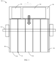
FIG. 1 illustrates a simplified schematic diagram of a switching apparatus according to some embodiments of the present disclosure; -
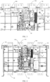
FIG. 2 illustrates an exploded diagram of a switching apparatus according to some embodiments of the present disclosure; -
FIGS. 3 and 4 illustrate structural schematic diagrams of the assembly of the actuation assembly and the breaking assembly according to some embodiments of the disclosure; -
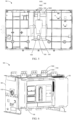
FIG. 5 illustrates a structural schematic diagram of a middle cover according to some embodiments of the present disclosure; and -
FIG. 6 illustrates a structural schematic diagram of a switching apparatus according to some embodiments of the present disclosure. - Embodiments of the present disclosure will be described in more detail below with reference to the accompanying drawings. Although certain embodiments of the present disclosure are shown in the accompanying drawings, it should be understood that the present disclosure may be implemented in various forms and should not be construed as limited to embodiments set forth herein. Rather, these embodiments are provided for a more thorough and complete understanding of the present disclosure. It should be understood that the accompanying drawings and embodiments of the present disclosure are only for illustrative purposes and are not intended to limit the scope of protection of the present disclosure.
- In the description of embodiments of the present disclosure, the term "comprise" and similar terms should be interpreted as open inclusion, that is, "including but not limited to". The term "based on" should be interpreted as "based at least in part on". The term "an embodiment" or "the embodiment" should be interpreted as "at least one embodiment". The term "some embodiments" should be interpreted as "at least some embodiments". Other explicit and implicit definitions may also be included below. The terms "first", "second", etc. may refer to different or identical objects. Other explicit and implicit definitions may also be included below.
- As briefly mentioned previously, dual power transfer switches need the ability to connect and withstand short circuit currents. In other words, while ensuring that the switch can withstand the shock of the short-circuit current when connected, while being able to reliably interrupt when the circuit is opened. In order to meet these requirements, the mechanical structure and the connecting parts of the switch need to have sufficient strength and stability to withstand current shocks and to provide a reliable electrical connection.
- In conventional dual power transfer switches, the actuation assemblies are located on one side of the breaking assembly, or two sets of actuation assemblies are distributed on both sides of the breaking assembly. As the current level increases, the performance requirement of the dual power transfer switch also become increasingly higher. For example, at a current level of 1600 A, the energy required for the disconnecting component is relatively higher, and the impact on each component is also more intense. Therefore, regular on-site maintenance and overhaul of each component are required. More on-site maintenance and overhaul efforts tend to be focused on the actuation assembly. However, since the actuation assembly is typically difficult to disassemble and assemble, this makes on-site maintenance work extremely challenging.
- In order to solve or at least partially solve the above problems or other potential problems of the switching apparatus of the conventional scheme, embodiments of the present disclosure provide a switching apparatus scheme. The breaking assembly, the actuation assembly and the middle cover of the switching apparatus cooperate together, which can enhance the reliability of a product and facilitate on-site maintenance. Furthermore, the transmission component of the breaking assembly is arranged along the direction of the main shaft and connected to the main shaft to achieve energy transmission and rotation functions. The positioning bracket of the breaking assembly is provided with a first positioning part for positioning and supporting to ensure the correct position of the transmission component and the actuation assembly.
- By detachably coupling the second positioning part of the actuation assembly and the first positioning part, the actuation assembly can be conveniently connected or detached to facilitate on-site maintenance and repair of the actuation assembly. The coupling between the motive power input portion and the motive power output portion enables the actuation assembly to transmit a driving force to the breaking unit of the breaking assembly, so that the actuation assembly can effectively drive the movable contact of the breaking unit to rotate between the open position and a closed position.
- The middle cover may allow the motive power output portion to pass through the opening portion and form a coupling with the motive power input portion to achieve an energy transmission and a driving effect, to ensure a good physical connection and coupling. Meanwhile, the auxiliary positioning part is coupled between the first positioning part and the second positioning part in the direction of the main shaft, which can provide additional positioning bracket in the direction of the main shaft, and ensure accurate positioning and stability between the separation assembly and the actuation assembly.
- An exemplary structure of the
switching apparatus 100 will be described below with reference toFIGS. 1 to 6 . Theswitching apparatus 100 such as a dual power transfer switch according to embodiments of the present disclosure are used to realize switching and changeover between two power supplies. The dual power transfer switch includes a mechanical or electronic component and has the function of automatic or manual operation. The dual power transfer switch is used for switching a load from one power supply to another power supply during a fault or maintenance period of one power supply to ensure continuous power supply of the load. - In a normal working state, the dual power transfer switch connects the load to one power supply. When one power supply has a fault or needs maintenance, the
switching apparatus 100 detects a change in a power supply state and switches the load from one power supply to another by operating the dual power transfer switch to avoid interruption or damage to the load. Therefore, by using the dual power transfer switch, theswitching apparatus 100 can implement redundancy and switching of the power supply and provide reliable power supply of the dual power supply. - As shown in
FIGS. 1 to 5 , theswitching apparatus 100 provided according to embodiments of the present disclosure generally include a breakingassembly 110, anactuation assembly 120, and amiddle cover 130. Theactuation assembly 120 is detachably coupled to the breakingassembly 110 through themiddle cover 130, and theactuation assembly 120 is controlled by thecontrol component 140 to drive the breakingassembly 110 to execute an action of switching a power supply or shutting off the power supply. - Furthermore, the breaking
assembly 110 includes amain shaft 1101, atransmission component 1102, and at least onebreaking unit 1104. Themain shaft 1101 provides support and power transmission functions. Thetransmission component 1102 is located on themain shaft 1101 and arranged in the direction A of main shaft. - The
transmission component 1102 includes apositioning bracket 11021 and a motivepower input portion 11023. Thepositioning bracket 11021 has afirst positioning part 11022 for positioning and supporting to ensure the correct position and stability of theactuation assembly 120. The motivepower input portion 11023 is located at one side of thedivision assembly 110 in the radial direction B and can receive and transmit power. The motivepower input portion 11023 is coupled to the at least onebreaking unit 1104 to transmit a drive force to thedrive member 1102 and the movable contact of thebreaking unit 1104. - Furthermore, the
actuation assembly 120 includes asecond positioning part 12011 and a motivepower output portion 12013. Thesecond positioning part 12011 is detachably coupled to thefirst positioning part 11022, and the motivepower output portion 12013 is coupled to the motivepower input portion 11023. Theactuation assembly 120 is arranged to achieve driving a movable contact of the at least onebreaking unit 1104 to rotate around themain shaft 1101 between an open position and a closed position via coupling between the motivepower input portion 11023 and the motivepower output portion 12013. In some embodiments, the motivepower input portion 11023 and the motivepower output portion 12013 may transmit power and effect mechanical movement by way of intermeshed gearing or linkage connections. The gear is used to transmit force and rotational movement, and the connecting rod can achieve transmission of force and movement conversion. The selection of this in embodiments of the present disclosure depends on specific requirements and application scenarios. - By detachably coupling the
second positioning part 12011 and thefirst positioning part 11022, theactuation assembly 120 can be conveniently connected or detached. The coupling of thepower output portion 12013 and thepower input portion 11023 enables theactuation assembly 120 to transmit the driving force to thebreaking unit 1104. By means of the coupling between the motivepower input portion 11023 and the motivepower output portion 12013, theactuation assembly 120 can effectively drive the movable contact to rotate between the open position and the closed position, thereby providing an efficient and reliable switch operation, and ensuring the stability and maintainability of the apparatus. - Furthermore, the
middle cover 130 is coupled to the breakingassembly 110 and arranged between the breakingassembly 110 and theactuation assembly 120. - The
middle cover 130 includes anopening portion 1301 and anauxiliary positioning part 1302. Theopening portion 1301 is arranged to allow at least one of the motivepower input portion 11023 and the motivepower output portion 12013 to pass therethrough and to be coupled with each other, thereby realizing energy transmission and a driving effect. Theopening portion 1301 can secure good physical connection and coupling. - The
auxiliary positioning part 1302 is coupled between thefirst positioning part 11022 and thesecond positioning part 12011 in the direction A of the main shaft. Such an arrangement provides additional positioning support to ensure accurate positioning and stability between theactuation assembly 120 and the breakingassembly 110. - Therefore, the
opening portion 1301 and theauxiliary positioning part 1302 of themiddle cover 130 enable the motivepower input portion 11023 and the motivepower output portion 12013 to pass through and be effectively coupled, thereby ensuring the reliability, stability and good positioning support of theswitching apparatus 100. Meanwhile, theactuation assembly 120 is detachably coupled to the breakingassembly 110, making on-site maintenance easier. - In some embodiments, in the breaking
assembly 110, at least onebreaking unit 1104 includes a plurality of breakingunits 1104. The plurality of breakingunits 1104 are distributed at both sides of thetransmission component 1102 along the direction A of the main shaft. Eachbreaking unit 1104 has an independent function and operation mechanism and they can work at the same time according to specific requirements and application scenarios. - Furthermore, in the
transmission component 1102, the plurality of breakingunits 1104 are distributed on both sides of thetransmission component 1102 along the direction A of the main shaft in equal numbers. - By distributing the plurality of breaking
units 1104 on both sides of thetransmission component 1102 in the equal number, a more uniform force distribution and breaking effect may be achieved. This layout may also increase the stability and the balance of thetransmission component 1102. Since the number and positions of thedivision units 1104 are the same, thetransmission component 1102 can maintain balanced force distribution during working, thereby reducing uneven load and vibration, and improving the reliability of thetransmission component 1102. The distribution manner can also achieve symmetrical force distribution, reduce the load and wear of thetransmission component 1102, and prolong the service life thereof. - As shown in
FIGS. 3-5 , in some embodiments, thefirst positioning part 11022 of thetransmission component 1102 is located outward of the breakingassembly 110 in the radial direction B to ensure accurate positioning and stability of the breakingassembly 110 during operation. Thefirst positioning part 11022 includes at least two first positioning holes 11024 which are respectively disposed at both ends of thepositioning bracket 11021 along the width direction C of themiddle cover 130 and perpendicular to the direction A of the main shaft. - In some embodiments, the
actuation assembly 120 includes a pair ofpositioning side plates 1201 spaced apart a predetermined distance in the direction A of the main shaft. Meanwhile, thesecond positioning part 12011 includes at least two pairs of second positioning holes 12012 and at least two positioning pins 1202. The at least two second positioning holes 12012 are arranged on the pair ofside plates 1201 respectively, and the at least two first positioning holes 11024 are located between the at least two pairs of second positioning holes 12012 respectively, and aligned in the direction A of the main shaft to ensure the positioning accuracy and reliability. - In addition, the at least two
positioning pins 1202 pass through the at least two second positioning holes 1212 and the at least two first positioning holes 11024. By fixing thefirst positioning part 11022 and thesecond positioning part 12011 by thepositioning pin 1202, theactuation assembly 120 is stably positioned and connected to ensure the correct positioning and alignment of theactuation assembly 120 in theswitching apparatus 100 to realize accurate operation and reliable functions. The combination of thesecond positioning hole 12012, thefirst positioning hole 11024 and thepositioning pin 1202 enables the executingassembly 120 to be limited in theswitching apparatus 100 perpendicular to the direction A of the main shaft, and maintain a stable and reliable position. For example, the locatingpin 1202 may be a snapspring locating pin 1202. - As shown in
FIG. 5 , in some embodiments, theauxiliary positioning part 1302 of themiddle cover 130 includes at least two pairs of shaft hole portions. The at least two pairs of shaft hole portions are respectively arranged between the at least two pairs of second positioning holes 12012 and the at least two first positioning holes 11024 in the direction A of main shaft. - Each pair of shaft hole portions includes a shaft hole through which the
positioning pin 1202 passes. By thepositioning pin 1202 passing through the shaft hole, a reliable connection is established between theauxiliary positioning part 1302 and thefirst positioning part 11022 and thesecond positioning part 12011 to ensure that they maintain a correct position and alignment. - The shaft hole portion of the
auxiliary positioning part 1302 is used to increase the positioning precision and reliability. They provide additional support and positioning points to ensure that thefirst positioning part 11022 and thesecond positioning part 12011 maintain stable and accurate positioning during operation, thereby ensuring the accurate operation and reliability functions of theswitching apparatus 100. - Furthermore, the
auxiliary positioning part 1302 includes afirst segment 13021 and asecond segment 13022 in the direction A of main shaft. When thefirst positioning part 11022 passes through the penetratingportion 1303 of themiddle cover 130, thefirst positioning part 11022 is located between thefirst segment 13021 and thesecond segment 13022. Thefirst segment 13021 and thesecond segment 13022 are respectively coupled between thefirst positioning part 11022 and thesecond positioning part 12011. - In some embodiments, the
main shaft 1101 is used to transmit power and effect rotation, in some cases, themain shaft 1101 comprises a plurality of main shaft segments arranged in at least one of thebreaking unit 1104 and thetransmission component 1102. - Each of the main shaft segments includes a first coupling portion and a second coupling portion located at both ends of the shaft direction, and the two coupling portions are located at both respective ends of the main shaft segment to achieve coupling and power transmission between the main shaft segments.
- Specifically, the first coupling portion matches the second coupling portion of the adjacent main shaft segment to achieve the coupling connection. Such a coupling connection can effectively transfer power, so that the main shaft segments can work in cooperation to jointly complete a required movement task.
- By arranging the plurality of main shaft segments in the at least one
breaking unit 1104 and thetransmission component 1102, more flexible and efficient power transfer can be achieved. The coupling portions of each of the main shaft segments can be interconnected to form an integral main shaft system for greater power output and more complex motion control. In this way, more flexible and efficient power transmission can be achieved, satisfying complex movement requirements. - As shown in
FIGS. 1 and6 , in some embodiments, thecontrol component 140 described above continues to be arranged in parallel with theactuation assembly 120 on the outside of themiddle cover 130 away from the breakingassembly 110 in order to facilitate the arrangement and operation of thecontrol component 140. For example, thecontrol section 140 includes a controller. - During the operation of the
switching apparatus 100, thecontrol component 140 of theswitching apparatus 100 collects and monitors the state of the power supply in real time to ensure that the load obtains a reliable power supply. In some embodiments, theswitching apparatus 100 includes apower supply end 1103 and aload end 140. Thepower supply end 1103 includes afirst power supply 11031 and asecond power supply 11032 that provide power supply. Theload end 140 may be coupled to multiple loads. - Furthermore, the
control component 140 is connected to a power supply through a sampling line and collects state information about the power supply in real time. The state information includes parameters such as a voltage, a current, and a frequency of a power supply. By monitoring the information, thecontrol component 140 can know a current working state of the power supply and determine whether the power supply is normal or faulty. When thecontrol component 140 monitors that the power supply state is abnormal, for example, the voltage is excessively high or low, and the frequency is unstable, thecontrol component 140 sends a relevant instruction according to the monitored power supply state information. - These instructions will drive the switching
apparatus 100 to switch between thefirst power supply 11031 and thesecond power supply 11032 to provide a reliable power supply for the load. This switching operation can ensure that when thefirst power supply 11031 fails, thesecond power supply 11032 can take over immediately and continue supply power to the load, thereby ensuring the continuity and reliability of the system. For example, thefirst power supply 11031 can include a primary power supply that provides power to theswitching apparatus 100 through a power grid (e. g., mains electricity) or other external power supply. Thesecond power supply 11032 may be a battery, a generator, or other reliable backup power device. - As shown in
FIGS. 1 and6 , in some embodiments, theswitching apparatus 100 also includes afront cover 150 and a pair ofend plates 160. Thefront cover 150 serves as protection and packaging in theswitching apparatus 100. Thefront cover 150 is coupled with themiddle cover 130 and covers thecontrol component 140 and theactuation assembly 120. By installing thefront cover 150, thecontrol component 140 and theactuation assembly 120 are additionally protected from external environment interference and physical damage. Therefore, thefront cover 150 is generally required to be considered easy to operate and maintain, so that the user can conveniently access thecontrol member 140 and theactuation assembly 120 and perform necessary operation and maintenance. - The pair of
end plates 160 are respectively arranged at both ends of the breakingassembly 110 in the direction A of main shaft, and used for supporting and fixing to ensure stability and reliability of theswitching apparatus 100. By arrangingend plate 160, breakingassembly 110 is well supported and remains stable during operation. This helps to accurately realize the open position and closed position operation and ensure the normal operation of theswitching apparatus 100. In addition, theend plate 160 may also provide additional safety protection. They may prevent thebreaking assemblies 110 from breaking away or accidentally moving during operation, thereby reducing the risk of an accident. - Implementations of the present disclosure have been described above. The above description is illustrative, not exhaustive, and is not limited to the disclosed implementations. Many modifications and variations will be apparent to those of ordinary skill in the art without departing from the scope and spirit of the described implementations. The terminology used herein is chosen to best explain the principles, practical applications, or improvements to the technology in the market, or to enable other persons of ordinary skill in the art to understand the various implementations disclosed herein.
Claims (12)
- A switching apparatus, characterized by comprising:a breaking assembly (110) comprising a main shaft (1101) and a transmission component (1102) arranged along a direction A of the main shaft and at least one breaking unit (1104), wherein the transmission component (1102) comprises a positioning bracket (11021) with a first positioning part (11022) and a motive power input portion (11023) located on one side of the breaking assembly (110) in a radial direction B;an actuation assembly (120), comprising a second positioning part (12011) detachably coupled to the first positioning part (11022) and a motive power output portion (12013) coupled to the motive power input portion (11023), wherein the actuation assembly (120) is arranged to drive a movable contact of the at least one breaking unit (1104) to rotate around the main shaft (1101) between an open position and a closed position via coupling between the motive power input portion (11023) and the motive power output portion (12013); anda middle cover (130) coupled to the breaking assembly (110) and arranged between the breaking assembly (110) and the actuation assembly (120), and comprising an opening portion (1301) adapted for one of the motive power input portion (11023) and the motive power output portion (12013) to pass through and an auxiliary positioning part (1302), wherein the auxiliary positioning part (1302) is coupled between the first positioning part (11022) and the second positioning part (12011) in the direction A of the main shaft.
- The switching apparatus of claim 1, characterized in that the first positioning part (11022) is located on outside of the breaking assembly (110) in the radial direction B, and comprises:
at least two first positioning holes (11024) respectively arranged at both ends of the positioning bracket (11021) along a width direction C of the middle cover (130) perpendicular to the direction A of the main shaft. - The switching apparatus of claim 2, characterized in that the actuation assembly (120) comprises a pair of positioning side plates (1201) spaced apart by a predetermined distance along the direction A of the main shaft, and the second positioning part (12011) comprises:at least two pairs of second positioning holes (12012) respectively arranged on the pair of positioning side plates (1201), wherein the at least two first positioning holes (11024) are respectively located between the at least two pairs of second positioning holes (12012) and aligned to each other along the direction A of the main shaft; andat least two positioning pins (1202) respectively passing through the at least two second positioning holes (12012) and the at least two first positioning holes (11024).
- The switching apparatus of claim 3, characterized in that the auxiliary positioning part (1302) comprises:
at least two pairs of shaft hole portions, respectively arranged between the at least two pairs of second positioning holes (12012) and the at least two first positioning holes (11024) in the direction A of the main shaft, and comprising shaft holes for the positioning pins (1202) to pass through. - The switching apparatus of any of claims 1 to 4, characterized in that the at least one breaking unit (1104) comprises:
a plurality of breaking units (1104) distributed on both sides of the transmission component (1102) along the direction A of the main shaft. - The switching apparatus of claim 5, characterized in that the plurality of breaking units (1104) are distributed on both sides of the transmission component (1102) along the direction A of the main shaft in equal numbers.
- The switching apparatus of any of claims 1 to 4 and 6, characterized in that the motive power input portion (11023) and the motive power output portion (12013) comprise gears engaged with each other.
- The switching apparatus of any of claims 1 to 4 and 6, characterized by further comprising:
a control component (140) arranged in parallel with the actuation assembly (120) on an outer side of the middle cover (130) away from the breaking assembly (110). - The switching apparatus of claim 8, characterized by further comprising:
a front cover (150) coupled to the middle cover (130) and covering the control component (140) and the actuation assembly (120). - The switching apparatus of any of claims 1 to 4, 6 and 8, characterized in that the main shaft (1101) comprises a plurality of main shaft segments respectively arranged in the at least one breaking unit (1104) and the transmission component (1102), wherein each main shaft segment comprises a first coupling portion and a second coupling portion at both axial ends, the first coupling portion is adapted to couple with the second coupling portion of an adjacent main shaft segment to transmit motive power.
- The switching apparatus of any of claims 1 to 4, 6 and 8, characterized by further comprising:
a pair of end plates (160) respectively arranged at both ends of the breaking assembly (110) in the direction A of the main shaft. - The switching apparatus of any of claims 1 to 4, 6 and 8, characterized in that the switching apparatus at least comprises a dual power transfer switch.
Applications Claiming Priority (1)
| Application Number | Priority Date | Filing Date | Title |
|---|---|---|---|
| CN202420021424.5U CN221960854U (en) | 2024-01-04 | 2024-01-04 | Switching device |
Publications (1)
| Publication Number | Publication Date |
|---|---|
| EP4583137A1 true EP4583137A1 (en) | 2025-07-09 |
Family
ID=93271747
Family Applications (1)
| Application Number | Title | Priority Date | Filing Date |
|---|---|---|---|
| EP24307127.1A Pending EP4583137A1 (en) | 2024-01-04 | 2024-12-17 | Switching apparatus |
Country Status (2)
| Country | Link |
|---|---|
| EP (1) | EP4583137A1 (en) |
| CN (1) | CN221960854U (en) |
Citations (6)
| Publication number | Priority date | Publication date | Assignee | Title |
|---|---|---|---|---|
| US6177641B1 (en) * | 1998-04-17 | 2001-01-23 | Schneider Electric Sa | Plug-in circuit breaker discharge and disengagement energy storage control device used during extraction of breaker |
| US20080087534A1 (en) * | 2006-10-17 | 2008-04-17 | Ls Industrial Systems Co., Ltd | Air circuit breaker |
| US7863534B2 (en) * | 2008-04-15 | 2011-01-04 | General Electric Company | Spring discharge mechanism for circuit breaker |
| US20150041293A1 (en) * | 2013-08-07 | 2015-02-12 | Abb S.P.A. | Circuit breaker |
| CN114823178A (en) * | 2022-05-05 | 2022-07-29 | 沈阳斯沃电器有限公司 | Automatic change-over switch |
| CN117012568A (en) * | 2022-11-29 | 2023-11-07 | 伊顿辉能低压电器(江苏)有限公司 | Automatic change-over switch |
-
2024
- 2024-01-04 CN CN202420021424.5U patent/CN221960854U/en active Active
- 2024-12-17 EP EP24307127.1A patent/EP4583137A1/en active Pending
Patent Citations (6)
| Publication number | Priority date | Publication date | Assignee | Title |
|---|---|---|---|---|
| US6177641B1 (en) * | 1998-04-17 | 2001-01-23 | Schneider Electric Sa | Plug-in circuit breaker discharge and disengagement energy storage control device used during extraction of breaker |
| US20080087534A1 (en) * | 2006-10-17 | 2008-04-17 | Ls Industrial Systems Co., Ltd | Air circuit breaker |
| US7863534B2 (en) * | 2008-04-15 | 2011-01-04 | General Electric Company | Spring discharge mechanism for circuit breaker |
| US20150041293A1 (en) * | 2013-08-07 | 2015-02-12 | Abb S.P.A. | Circuit breaker |
| CN114823178A (en) * | 2022-05-05 | 2022-07-29 | 沈阳斯沃电器有限公司 | Automatic change-over switch |
| CN117012568A (en) * | 2022-11-29 | 2023-11-07 | 伊顿辉能低压电器(江苏)有限公司 | Automatic change-over switch |
Also Published As
| Publication number | Publication date |
|---|---|
| CN221960854U (en) | 2024-11-05 |
Similar Documents
| Publication | Publication Date | Title |
|---|---|---|
| US7142950B2 (en) | Methods and apparatus for providing and distributing standby power | |
| CN111916316A (en) | Bipolar circuit breaker with display function | |
| CN221960854U (en) | Switching device | |
| CN102543495B (en) | Double-power automatic transfer switch | |
| KR101095016B1 (en) | 3-position operation device of gas insulated switchgear | |
| CN114242477B (en) | A neutral pole overlapping conversion structure and automatic transfer switch electrical appliance | |
| CN216957790U (en) | Neutral pole overlapping conversion structure and automatic transfer switching device | |
| CN216698206U (en) | Integrated subway contact net switching device | |
| CN211930336U (en) | Power supply automatic conversion system and power distribution cabinet using same | |
| CN224123934U (en) | Dual-power switching type power distribution cabinet | |
| KR200387632Y1 (en) | Automatic Transfer Switch | |
| CN202616062U (en) | Contact system used for dual supply change-over switch | |
| CN223539499U (en) | A modular disconnector structure | |
| CN221040867U (en) | Isolation mechanism and switch cabinet thereof | |
| CN208521809U (en) | Contact structure of an automatic transfer switch | |
| CN105448557A (en) | Automatic change-over switch | |
| CN104092281A (en) | Alternating-current dual-power switching method | |
| CN224123937U (en) | Dual-power switching system and low-voltage magnetic control circuit breaker thereof | |
| CN201570419U (en) | Auxiliary switch for high pressure switch | |
| CN111696800B (en) | High-voltage fixed breaker interlocking device for wind power generation box transformer substation and box transformer substation | |
| CN119446833A (en) | A modular isolating switch structure | |
| CN223828405U (en) | Operating device | |
| CN223006697U (en) | A bushing for an isolating switch | |
| CN120728514B (en) | Energy storage systems, emergency stop control methods for energy storage systems, and electrical equipment. | |
| KR20250125056A (en) | The 3-position disconnecting mechanism of power line switch |
Legal Events
| Date | Code | Title | Description |
|---|---|---|---|
| PUAI | Public reference made under article 153(3) epc to a published international application that has entered the european phase |
Free format text: ORIGINAL CODE: 0009012 |
|
| STAA | Information on the status of an ep patent application or granted ep patent |
Free format text: STATUS: THE APPLICATION HAS BEEN PUBLISHED |
|
| AK | Designated contracting states |
Kind code of ref document: A1 Designated state(s): AL AT BE BG CH CY CZ DE DK EE ES FI FR GB GR HR HU IE IS IT LI LT LU LV MC ME MK MT NL NO PL PT RO RS SE SI SK SM TR |
|
| STAA | Information on the status of an ep patent application or granted ep patent |
Free format text: STATUS: REQUEST FOR EXAMINATION WAS MADE |
|
| 17P | Request for examination filed |
Effective date: 20251215 |
|
| GRAP | Despatch of communication of intention to grant a patent |
Free format text: ORIGINAL CODE: EPIDOSNIGR1 |
|
| STAA | Information on the status of an ep patent application or granted ep patent |
Free format text: STATUS: GRANT OF PATENT IS INTENDED |