EP4583135A1 - Transmission mechanism for a switch apparatus and switch apparatus - Google Patents
Transmission mechanism for a switch apparatus and switch apparatus Download PDFInfo
- Publication number
- EP4583135A1 EP4583135A1 EP24307032.3A EP24307032A EP4583135A1 EP 4583135 A1 EP4583135 A1 EP 4583135A1 EP 24307032 A EP24307032 A EP 24307032A EP 4583135 A1 EP4583135 A1 EP 4583135A1
- Authority
- EP
- European Patent Office
- Prior art keywords
- breaking
- pair
- gear
- transmission mechanism
- switch apparatus
- Prior art date
- Legal status (The legal status is an assumption and is not a legal conclusion. Google has not performed a legal analysis and makes no representation as to the accuracy of the status listed.)
- Pending
Links
Images






Classifications
-
- H—ELECTRICITY
- H01—ELECTRIC ELEMENTS
- H01H—ELECTRIC SWITCHES; RELAYS; SELECTORS; EMERGENCY PROTECTIVE DEVICES
- H01H71/00—Details of the protective switches or relays covered by groups H01H73/00 - H01H83/00
- H01H71/02—Housings; Casings; Bases; Mountings
- H01H71/0264—Mountings or coverplates for complete assembled circuit breakers, e.g. snap mounting in panel
- H01H71/0271—Mounting several complete assembled circuit breakers together
-
- H—ELECTRICITY
- H01—ELECTRIC ELEMENTS
- H01H—ELECTRIC SWITCHES; RELAYS; SELECTORS; EMERGENCY PROTECTIVE DEVICES
- H01H3/00—Mechanisms for operating contacts
- H01H3/22—Power arrangements internal to the switch for operating the driving mechanism
-
- H—ELECTRICITY
- H01—ELECTRIC ELEMENTS
- H01H—ELECTRIC SWITCHES; RELAYS; SELECTORS; EMERGENCY PROTECTIVE DEVICES
- H01H3/00—Mechanisms for operating contacts
- H01H3/32—Driving mechanisms, i.e. for transmitting driving force to the contacts
-
- H—ELECTRICITY
- H01—ELECTRIC ELEMENTS
- H01H—ELECTRIC SWITCHES; RELAYS; SELECTORS; EMERGENCY PROTECTIVE DEVICES
- H01H3/00—Mechanisms for operating contacts
- H01H3/32—Driving mechanisms, i.e. for transmitting driving force to the contacts
- H01H3/40—Driving mechanisms, i.e. for transmitting driving force to the contacts using friction, toothed, or screw-and-nut gearing
-
- H—ELECTRICITY
- H01—ELECTRIC ELEMENTS
- H01H—ELECTRIC SWITCHES; RELAYS; SELECTORS; EMERGENCY PROTECTIVE DEVICES
- H01H71/00—Details of the protective switches or relays covered by groups H01H73/00 - H01H83/00
- H01H71/02—Housings; Casings; Bases; Mountings
- H01H71/0264—Mountings or coverplates for complete assembled circuit breakers, e.g. snap mounting in panel
- H01H71/0271—Mounting several complete assembled circuit breakers together
- H01H2071/0285—Provisions for an intermediate device between two adjacent circuit breakers having the same general contour but an auxiliary function, e.g. cooling, isolation, wire guiding, magnetic isolation or screening
-
- H—ELECTRICITY
- H01—ELECTRIC ELEMENTS
- H01H—ELECTRIC SWITCHES; RELAYS; SELECTORS; EMERGENCY PROTECTIVE DEVICES
- H01H2300/00—Orthogonal indexing scheme relating to electric switches, relays, selectors or emergency protective devices covered by H01H
- H01H2300/018—Application transfer; between utility and emergency power supply
Definitions
- Example embodiments of the present disclosure relate generally to a field of electrical device, and more particularly, to a transmission mechanism for a switch apparatus and a switch apparatus.
- An automatic transfer switch apparatus is a key component for an emergency or backup power system.
- the automatic transfer switch apparatus can automatically switch a load from a primary power supply to a backup power supply when the primary power supply fails, thereby ensuring the continuous supply of power.
- the transfer switch apparatus generally includes a PC level, a CC level and a CB level according to short circuit capability.
- a PC level dual power supply transfer switch apparatus it needs to have a capability of being able to connect and bear a short circuit current, a product design needs to ensure a connection capability and a breaking capability of the transfer switch apparatus, this puts forward a higher and more difficult requirement on the design, especially as the current level increases, leading to higher performance demands.
- the transmission mechanism further includes: a plurality of connection pins parallel to axis of the at least one breaking gear and uniformly arranged between the pair of coupling members (104) in a circumferential direction and are fixedly coupled to the breaking gear, and wherein the pair of bracket plates include a plurality of arc-shaped grooves respectively for the plurality of connection pins to pass through to allow the at least one breaking gear to drive, via the plurality of connection pins, the pair of coupling members to rotate.
- the transmission mechanism further includes: a plurality of stepped shafts, two ends of the plurality of stepped shafts in an axial direction being respectively coupled to the pair of bracket plates, and a part of the plurality of stepped shafts being respectively coupled in shaft holes of the at least one intermediate gear and the at least one breaking gear to respectively arranged the at least one intermediate gear and the at least one breaking gear between the pair of bracket plates.
- the at least one intermediate gear includes a pair of intermediate gears, the pair of intermediate gears share an intermediate gear shaft, and the at least one breaking gear includes a pair of breaking gears, the pair of breaking gears include a pair of breaking rotation shafts, and wherein the transmission mechanism further includes: a pair of side plates arranged between the pair of intermediate gears and between the pair of breaking gears in the axial direction, wherein the pair of breaking gears respectively include a coupling structure to be coupled with the breaking connection member of the breaking unit.
- the pair of breaking rotation shafts are fixedly coupled to the pair of side plates, respectively, and the intermediate gear rotation shaft passes through the pair of side plates to be fixedly coupled to the pair of side plates.
- the coupling member or the coupling structure includes a spline groove or a spline shaft.
- one of the pair of breaking connection members includes a spline groove, and the other of the pair of breaking connection members includes a spline shaft.
- the spline groove includes a radial fool-proof groove
- the spline shaft includes a radial fool-proof protrusion
- the switching means further includes: a control unit arranged on a same side of the transmission mechanism and the breaking unit in the radial direction as the power mechanism, and being adapted to control the power output of the power mechanism.
- the transmission mechanism includes three stepped shafts 106, wherein two stepped shafts 106 serve as gear shafts of the intermediate gear 101 and the breaking gear 102, and the other stepped shaft 106 is used for fixing the bracket plate 1031.
- the pair of coupling members 104 are respectively coupled to a side of the pair of bracket plates 1031 opposite to the breaking gear 102, and are coaxial with at least one breaking gear 102.
- Each coupling member 104 is adapted to be coupled with the breaking connection members 2021 of the breaking unit 202 respectively to drive the movable contact to move.
- the spline shaft can be inserted into the spline groove 1043, thereby realizing coupling of the transmission mechanism 100 with the adjacent breaking unit 202.
- Connections among the plurality of breaking units 202 are also similar, both being for inserting the spline shaft into the spline groove 1043, so as to achieve assembly and also achieve power transmission at the same time.
- the transmission mechanism 100 also includes a housing 108.
- the housing 108 may include a pair of support plates 1081 to allow the pair of bracket plates 1031 to be arranged therebetween.
- the pair of support plates 1081 may be coupled together in a suitable manner such as a snap-fit connection, a fastener connection, or an adhesive bond.
- the pair of support plates 1081 may respectively include an opening 1082 respectively the pair of coupling members 104 to the breaking unit 202 to facilitate coupling between the breaking connection member 2021 of the breaking unit 202 and the pair of coupling members 104.
- the pair of bracket plates 1031 may be made of a metal material, thereby improving the strength of the structure.
- the pair of support plates 1081 of the housing 108 may be made of a material such as plastic, thereby facilitating manufacturing of a mold while reducing costs.
- a rib structure may be provided on an inner wall of at least one bracket plate of the pair of support plates 1081 to improve strength of the support plate 1081.
- the transmission mechanism 100 may also include at least one long shaft 1084 through the pair of support plates 1081 and the pair of bracket plates 1031, respectively, to couple the pair of support plates 1081 and the pair of bracket plates 1031 together.
- at least one long shaft 1084 may extend in the axial direction beyond the pair of support plates 1081, respectively, to facilitate coupling with the adjacent breaking unit 202.
- the corresponding location of the breaking unit 202 may include a hole for receiving at least a part of the long shaft 1084 to assist completion of assembly between the transmission mechanism 100 and the adjacent breaking unit 202.
- the pair of bracket plates 1031 may have a coupling part 1032 at a side facing the power mechanism 201 to facilitate coupling of the transmission mechanism 100 with the power mechanism 201.
- the coupling part 1032 may include a protrusion part and a coupling hole 1035 provided on the protrusion part. The protrusion part can be at least partially inserted into the interior of the power mechanism 201 to enable a coupling pin to be inserted into the coupling hole, thereby realizing reliable positioning and assembly between the transmission mechanism 100 and the power mechanism 201.
- both the intermediate gear 101 and the breaking gear 102 respectively adopt a single gear structure, and are positioned by the gear bracket 103, thereby guaranteeing that a gear fitting dimension chain is the shortest and fitting tolerance is reduced.
- the breaking units at two sides of the transmission mechanism in a direction of the main shaft can be arranged symmetrically (the two sides have the same number of breaking units), so that parts can be shared as much as possible, thereby reducing costs and improving driving reliability.
- FIGS. 8 to 11 illustrate schematic views of a transmission mechanism 100 according to further embodiments of the present disclosure.
- the number of the intermediate gears 101 and the number of the breaking gears 102 are two (i.e., a pair).
- FIGS. 8 and 9 respectively illustrate perspective views of the transmission mechanism 100 as viewed at different angles, according to some embodiments of the present disclosure;
- FIG. 10 illustrates a view of a side plate 107 and the corresponding intermediate gear 101 and the breaking gear 102 of the transmission mechanism 100.
- the transmission mechanism 100 further includes a pair of side plates 107 that overlap each other.
- the pair of side plates 107 is arranged between the pair of intermediate gears 101 and the pair of breaking gears 102 in the axial direction.
- the pair of intermediate gears 101 shares an intermediate gear shaft 1011 which passes through the pair of side plates 107 for arranging the pair of intermediate gears 101 thereon.
- Each of the breaking gears 102 includes a breaking rotation shaft 1021, and is respectively coupled to a corresponding side plate 107 of the pair of side plates 107, as shown in FIG. 10 .
- An end of the breaking rotation shaft 1021 is coupled to a side of the side plate 107 adjacent to the other side plate 107 in a suitable manner such as riveting or welding, and the other end passes through the side plate 107 and is coupled to the breaking gear 102.
- the pair of breaking gears 102 respectively include a coupling structure 1022 to be coupled with the breaking connection member 2021 of the breaking unit 202. That is, in such an embodiment, the coupling members 104 may no longer be required, and the coupling structure 1022 on the breaking gear 102 may be directly adapted to be coupled with the break connection member 2021.
- the coupling structure 1022 may include the spline groove 1043 or the spline shaft.
- the coupling 1022 includes the spline groove 1043 as an example. It should be understood that the embodiment in which the coupling 1022 includes the spline shaft is also similar, and will not be described separately in the following.
- one of the pair of breaking connection members 2021 of the breaking unit 202 on a side adjacent to the transmission mechanism 100 includes a spline shaft, and the other breaking connection member 2021 includes the splined groove 1043.
- the spline shaft can be inserted into the spline groove 1043, thereby realizing coupling of the transmission mechanism 100 with the adjacent breaking unit 202.
- Connection members among the plurality of breaking units 202 are also similar, both being for inserting the spline shaft into the spline groove 1043, so as to achieve assembly and also achieve power transmission at the same time.
- the radial fool-proof groove 1041 is provided on the circumferential inner wall of a part of key grooves of the spline groove 1043.
- a radial fool-proof protrusion is provided on the circumferential outer wall of a part of keys of the spline shaft.
- the housing 108 of the transmission mechanism 100, etc. may also include the pair of support plates 1081, with the side plates 107 provided therebetween.
- the pair of support plates 1081 may be coupled together in a suitable manner such as a snap-fit connection, a fastener connection, or an adhesive bond.
- the pair of support plates 1081 may respectively include the groove 1083 to expose the pair of coupling members 104 to the breaking unit 202 to facilitate coupling between the breaking connection member 2021 of the breaking unit 202 and the pair of coupling members 104.
- Other structures of the housing 108 are similar to the structures of the housing 108 described in the embodiments shown in FIG. 4 to FIG. 7 , and are not separately described herein.
- the side plate 107 may be made of a metal material, thereby improving strength of structure.
- the part of the intermediate gear 101 radially exceeds beyond edges of the side plates 107 to mesh with the mechanism gear.
- the intermediate gear 101 and the breaking gear 102 both adopt a double-gear structure, a thickness of a single gear can be set thinner, thereby reducing costs and making the solutions easier to implement in process.
- the transmission portion is used as an independent modular design, thereby facilitating installation and maintenance.
Landscapes
- Gear Transmission (AREA)
Abstract
Description
- Example embodiments of the present disclosure relate generally to a field of electrical device, and more particularly, to a transmission mechanism for a switch apparatus and a switch apparatus.
- An automatic transfer switch apparatus (ATS) is a key component for an emergency or backup power system. The automatic transfer switch apparatus can automatically switch a load from a primary power supply to a backup power supply when the primary power supply fails, thereby ensuring the continuous supply of power. The transfer switch apparatus generally includes a PC level, a CC level and a CB level according to short circuit capability. For a PC level dual power supply transfer switch apparatus, it needs to have a capability of being able to connect and bear a short circuit current, a product design needs to ensure a connection capability and a breaking capability of the transfer switch apparatus, this puts forward a higher and more difficult requirement on the design, especially as the current level increases, leading to higher performance demands.
- In a first aspect of the present disclosure, a transmission mechanism for a switch apparatus is provided. The transmission mechanism includes: at least one intermediate gear arranged to mesh with a mechanism gear of a power mechanism of the switch apparatus; and at least one breaking gear arranged to mesh with the at least one intermediate gear and coupled to a breaking connection member of a breaking unit of the switch apparatus, the breaking unit being arranged at at least one end of the breaking gear in the axial direction for switching a load circuit between a first power supply and a second power supply, wherein the at least one breaking gear is adapted to be driven by the power mechanism via the at least one intermediate gear to in turn drive a moveable contact of the breaking unit to move between a first position and a second position via the breaking connection member, in the first position, the movable contact connects the first power supply to a load, in the second position, the movable contact connects the second power supply to the load.
- In some embodiments, the transmission mechanism further includes: a gear bracket including a pair of bracket plates arranged at ends of the at least one intermediate gear and the at least one breaking gear in the axial direction; and a pair of coupling members respectively coupled to sides of the pair of bracket plates opposite to the breaking gears and coaxial with the at least one breaking gear, wherein each of the pair of coupling members is adapted to be respectively coupled to the breaking connection member of the breaking unit to drive the movable contact to move.
- In some embodiments, the transmission mechanism further includes: a plurality of connection pins parallel to axis of the at least one breaking gear and uniformly arranged between the pair of coupling members (104) in a circumferential direction and are fixedly coupled to the breaking gear, and wherein the pair of bracket plates include a plurality of arc-shaped grooves respectively for the plurality of connection pins to pass through to allow the at least one breaking gear to drive, via the plurality of connection pins, the pair of coupling members to rotate.
- In some embodiments, the transmission mechanism further includes: a plurality of stepped shafts, two ends of the plurality of stepped shafts in an axial direction being respectively coupled to the pair of bracket plates, and a part of the plurality of stepped shafts being respectively coupled in shaft holes of the at least one intermediate gear and the at least one breaking gear to respectively arranged the at least one intermediate gear and the at least one breaking gear between the pair of bracket plates.
- In some embodiments, the at least one intermediate gear includes a pair of intermediate gears, the pair of intermediate gears share an intermediate gear shaft, and the at least one breaking gear includes a pair of breaking gears, the pair of breaking gears include a pair of breaking rotation shafts, and wherein the transmission mechanism further includes: a pair of side plates arranged between the pair of intermediate gears and between the pair of breaking gears in the axial direction, wherein the pair of breaking gears respectively include a coupling structure to be coupled with the breaking connection member of the breaking unit.
- In some embodiments, the pair of breaking rotation shafts are fixedly coupled to the pair of side plates, respectively, and the intermediate gear rotation shaft passes through the pair of side plates to be fixedly coupled to the pair of side plates.
- In some embodiments, the pair of bracket plates or the pair of side plates have a coupling part at a side facing the power mechanism to facilitate coupling of the transmission mechanism with the power mechanism.
- In some embodiments, a part of the at least one intermediate gear exceeds beyond edges of the pair of bracket plates or the pair of side plates in a radial direction to mesh with the mechanism gear.
- In some embodiments, the coupling member or the coupling structure includes a spline groove or a spline shaft.
- In some embodiments, a radial fool-proof groove is disposed on a circumferential inner wall of a part of key grooves of the spline groove ; or a radial fool-proof protrusion is provided on a circumferential outer wall of a part of keys of the spline shaft.
- In some embodiments, the transmission mechanism further includes: a housing including a pair of support plates to allow the pair of bracket plates or the pair of side plates to be arranged therebetween; and at least one long shaft passing through the pair of support plates and the pair of bracket plates or the pair of side plates, respectively, to couple the pair of support plates and the pair of bracket plates or the pair of side plates together.
- In some embodiments, the at least one long shaft respectively extends beyond the pair of bracket plates in an axial direction to be coupled with the breaking unit.
- In some embodiments, the pair of support plates respectively include an opening or a groove to expose the pair of connection members or coupling structure to the breaking unit.
- According to a second aspect of the embodiments of the present disclosure, a switch apparatus is provided. The switch apparatus includes: the transmission mechanism according to the first aspect, an axis of a breaking gear of the transmission mechanism is coaxial with a main shaft of the switch apparatus; a power mechanism arranged offset from the main shaft and including a mechanism gear meshed with the breaking gear; and a plurality of breaking units, respectively corresponding to a plurality of poles of a first power supply or a second power supply, and respectively coupled to at least one end of the transmission mechanism in an axial direction to enable a load circuit to switch between the first power supply and the second power supply.
- In some embodiments, each of the plurality of breaking units includes a pair of breaking connection members respectively arranged at both ends of the breaking unit in the axial direction and fixedly coupled to a movable contact, and one of the pair of breaking connection members in one of the plurality of breaking units adjacent to the transmission mechanism is adapted to be coupled directly or indirectly with the breaking gear, the other of the pair of breaking connection member is adapted to be coupled with the breaking connection member of the adjacent breaking unit to implement power transmission.
- In some embodiments, one of the pair of breaking connection members includes a spline groove, and the other of the pair of breaking connection members includes a spline shaft.
- In some embodiments, the spline groove includes a radial fool-proof groove, and the spline shaft includes a radial fool-proof protrusion.
- In some embodiments, the switching means further includes: a control unit arranged on a same side of the transmission mechanism and the breaking unit in the radial direction as the power mechanism, and being adapted to control the power output of the power mechanism.
- By adopting the transmission mechanism according to the embodiments of the present disclosure, fitting tolerance of the switch apparatus is lower, and maintenance of the power mechanism and the control unit is more convenient. In addition, the power mechanism, the transmission mechanism, and each of the plurality of breaking units adopt a modular structure. In this manner, adopting such a modular layout facilitates installation and maintenance of automatic transfer switch apparatus.
- It should be understood that what is described in this Summary is not intended to limit critical features or essential features of embodiments of the present disclosure, nor is it intended to limit a scope of the present disclosure. Other features of the present disclosure will become readily understood from following description.
- The above and other features, advantages, and aspects of various embodiments of the present disclosure will become more apparent with reference to following detailed description taken in conjunction with drawings. In the drawings, the same or similar reference signs denote the same or similar elements, wherein:
-
FIG. 1 illustrates a simplified schematic diagram of an overall architecture of a switch apparatus according to embodiments of the present disclosure; -
FIG. 2 illustrates a perspective view of a switch apparatus according to embodiments of the present disclosure; -
FIG. 3 illustrates an interior perspective view of a transmission mechanism and a power mechanism of a switch apparatus according to embodiments of the present disclosure; -
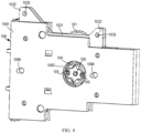
FIG. 4 illustrates a perspective view of a transmission mechanism of a switch apparatus according to embodiments of the present disclosure; -
FIG. 5 illustrates a perspective view of an intermediate gear and a breaking gear of a transmission mechanism meshing with each other according to embodiments of the present disclosure; -
FIG. 6 illustrates an exploded view of a transmission mechanism of a switch apparatus according to embodiments of the present disclosure; -
FIG. 7 illustrates a perspective view of a coupling member according to embodiments of the present disclosure; -
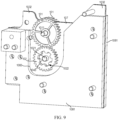
FIGS. 8 and9 illustrate perspective views of a transmission mechanism according to further embodiments of the present disclosure; -
FIG. 10 illustrates a partial perspective view of an interior of a transmission mechanism according to further embodiments of the present disclosure; and -
FIG. 11 illustrates a perspective view of a transmission mechanism and a breaking gear meshing with each other according to further embodiments of the present disclosure. - Embodiments of the present disclosure will be described in more detail below with reference to the drawings. Although certain embodiments of the present disclosure are shown in the drawings, it should be understood that the present disclosure may be implemented in various forms and should not be construed as limited to the embodiments set forth herein, but rather, these embodiments are provided for a thorough and complete understanding of the present disclosure. It should be understood that the drawings and embodiments of the present disclosure are only for illustrative purposes and are not intended to limit a scope of the present disclosure.
- It should be noted that titles of any section/subsection provided herein are not limiting. Various embodiments are described throughout herein, and any type of embodiment can be included under any section/subsection. Furthermore, embodiments described in any section/subsection may be combined in any manner with any other embodiments described in the same section/subsection and/or different sections/subsections.
- In the description of the embodiments of the present disclosure, the term "including" and the like should be understood as open-ended including, that is, "including but not limited to". The term "based on" should be read as "based at least in part on. " The term "one embodiment" or "the embodiment" should be read as "at least one embodiment. "The term "some embodiments" should be understood as "at least some embodiments. " Other explicit and implicit definitions may also be included below. The terms "first", "second", etc. may refer to different or identical objects. Other explicit and implicit definitions may also be included below.
- As mentioned briefly above, a PC level dual-supply switch apparatus needs to have a capability of being able to connect to and bear the t short circuit current. However, the current transfer switch apparatuses are complicated in structure, require a larger energy for the breaking unit due to structural arrangement, have a larger impact on parts, and require a higher strength.
- Embodiments of the present disclosure provide a switch apparatus and a
transmission mechanism 100 for the switch apparatus to solve, or at least partially solve, the described problems or other potential problems in conventional transfer switch apparatuses.FIG. 1 illustrates a simplified schematic diagram (top view) of an automatic transfer switch apparatus according to an embodiment of the present disclosure, andFIG. 2 illustrates a perspective view of the automatic transfer switch apparatus. Hereinafter, a concept according to the present disclosure will be described mainly by taking the dual-power supply transfer switch apparatus shown inFIGS. 1 and2 as an example. It should be understood that cases of more power transfer switch apparatuses are similar, and will not be described in detail hereinafter. - As shown in
FIGS. 1 and2 , in general, an automatic transfer switch apparatus according to embodiments of the present disclosure includes apower mechanism 201, a plurality of breakingunits 202, and atransmission mechanism 100. In some embodiments, the automatic transfer switch apparatus may also include acontrol unit 203 for controlling power output of a power unit. - The
power mechanism 201 includes a power component such as a motor, a mechanism gear, and a transmission assembly therebetween. An output shaft of the power unit can be rotated or stopped under the control of thecontrol unit 203 or the like. The rotation of the output shaft of the power unit can drive the mechanism gear to rotate via the transmission assembly, thereby outputting power. Thetransmission mechanism 100 according to embodiments of the present disclosure is arranged between the plurality of breakingunits 202 and coupled to thepower mechanism 201 to transmit power output by thepower mechanism 201 to the plurality of breakingunits 202 to achieve switching between two power supplies. The plurality of breakingunits 202 correspond to a plurality of poles of two power supplies, which are hereinafter referred to as a first power supply and a second power supply, respectively. For example, the first power supply may be a main power supply and the second power supply may be a backup power supply. -
FIG. 2 illustrates a perspective view of an automatic transfer switch apparatus according to embodiments of the present disclosure. As shown inFIG. 2 , the automatic transfer switch apparatus includes a plurality offirst terminals 205 for connecting a plurality of poles of the first power supply, a plurality ofsecond terminals 206 for connecting a plurality of poles of the second power supply, and aload terminal 207 for connecting a load. The automatic transfer switch apparatus may include a user input interface and/or a display component on a side of thepower mechanism 201 and thecontrol unit 203 away from thebreaking unit 202 and the transmission mechanism 100 (i.e. a side facing a user), so as to facilitate the user to operate and/or acquire information such as a state of the automatic transfer switch apparatus. - A
coupling plate 208 may be provided outside the outermost one of the plurality of breakingunits 202. Thecoupling plate 208 may facilitate installing the switch apparatus into a switch cabinet, and also facilitate ensuring strength of the entire switch apparatus. Anopening 2082 may be opened on thecoupling plate 208 to allow abreaking connection member 2021 of thebreaking unit 202 to leak out. - The
transmission mechanism 100 and the plurality of breakingunits 202 are arranged on the samemain shaft 204, that is to say, thetransmission mechanism 100 and the plurality of breakingunits 202 are arranged along themain shaft 204. This arrangement can ensure higher synchronization of the plurality of breakingunits 202. In addition, in some embodiments, the plurality of breakingunits 202 may be arranged at both ends of thetransmission mechanism 100 in the axial direction. In this way, extension of the switch apparatus can be facilitated, for example, the switch apparatus having more poles (for example, 6-8 poles) is expanded, thereby achieving a higher current level and improving reliability and security. - The
power mechanism 201 is arranged offset from themain shaft 204, and the mechanism gear meshes with anintermediate gear 101 in thetransmission mechanism 100 to thereby transmit power output from thepower mechanism 201 to the plurality of breakingunits 202 via thetransmission mechanism 100. In addition, thepower mechanism 201, thetransmission mechanism 100, and each of the plurality of breakingunits 202 adopt a modular structure. In this manner, adopting such a modular layout facilitates installation and maintenance of the switch apparatus. - Each of the breaking
units 202 includes a pair of breakingconnection members 2021. The pair of breakingconnection members 2021 are arranged coaxially with themain shaft 204, and are respectively arranged at both ends of thebreaking unit 202 in the axial direction. The pair of breakingconnection members 2021 are fixedly coupled inside thebreaking unit 202 to movable contacts. The movable contacts can switch between the first power supply and corresponding stationary contacts of the second power supply under an action of power of thepower mechanism 201, so as to implement power switching. - For the
breaking unit 202 adjacent to thetransmission mechanism 100, one of the pair of breaking connection members 2021 (i.e., thebreaking connection member 2021 adjacent to thetransmission mechanism 100 is directly or indirectly coupled to thetransmission mechanism 100, The otherbreaking connection member 2021 is coupled to thebreaking connection member 2021 of anotherbreaking unit 202 adjacent to thebreaking unit 202, so as to achieve the extension of the plurality of breakingunits 202 and the transmission of power. The plurality of breakingunits 202 can be connected to each other through thebreaking connection member 2021 and transmit power, thereby facilitating multi-pole extension. - In addition, in order to facilitate positioning between the breaking
unit 202 and thetransmission mechanism 100 and between a plurality of breakingunits 202, a positioning structure and a coupling structure may be included on thebreaking unit 202 and thetransmission mechanism 100. For example, in some embodiments, the locating structures may include raised or recessed structures provided on bothend housings 108 of each of the breakingcells 202 in the axial direction. For example, in some embodiments, an end of each breakingunit 202 in the axial direction is provided with one or more protrusions, and the other end is provided with one or more recesses at corresponding positions, so that when two breakingunits 202 are assembled, the recesses can accommodate the protrusions, thereby realizing the positioning of thebreaking unit 202. - The
transmission mechanism 100 according to embodiments of the present disclosure will be described below with reference toFIGS. 3 to 11 .FIG. 3 illustrates a schematic diagram in which thepower mechanism 201 and thetransmission mechanism 100 are coupled to each other, in order to illustrate an internal structure, thepower mechanism 201 and a part of thehousing 108 of thetransmission mechanism 100 are hidden. As shown inFIG. 3 , generally, thetransmission mechanism 100 according to embodiments of the present disclosure adopts a gear transmission structure, and specifically includes at least oneintermediate gear 101 and at least onebreaking gear 102. - The at least one
intermediate gear 101 is adapted to mesh with a mechanical gear of thepower mechanism 201. The at least onebreaking gear 102 is coupled to theintermediate gear 101 and is coaxially coupled to thebreaking connection member 2021 of thebreaking unit 202, thereby achieving transmission of power from thepower mechanism 201 to the plurality of breakingunits 202. Specifically, thebreaking gear 102 can be driven by thepower mechanism 201 via theintermediate gear 101 to further drive the movable contact of thebreaking unit 202 to move between a first position and a second position via thebreaking connection member 2021. In the first position, the movable contact connects the first power supply to a load. In the second position, the movable contact connects the second power supply to the load. Between the first position and the second position, there may also be a third position in which both the movable contact and the two stationary contacts are decoupled. In this way, switching of a load circuit between the first power supply and the second power supply and a disconnected state in the third position are achieved. -
FIGS. 4 to 7 illustrate views of thetransmission mechanism 100 according to some embodiments of the present disclosure. In embodiments shown inFIGS. 4 to 7 , the number of theintermediate gear 101 and the number of thebreaking gear 102 are one, respectively.FIG. 4 illustrates a perspective view of thetransmission mechanism 100, according to some embodiments of the present disclosure;FIG. 5 illustrates an internal partial view of thetransmission mechanism 100; andFIG. 6 illustrates an exploded view of thetransmission mechanism 100. As shown inFIGS. 4 to 6 , in some embodiments, thetransmission mechanism 100 also includes agear bracket 103 and a pair ofcoupling members 104 for supporting and assembling theintermediate gear 101 and thebreaking gear 102 together. - In some embodiments, as shown in
FIG. 6 , thegear bracket 103 may include a pair ofbracket plates 1031. The pair ofbracket plates 1031 are arranged at ends of theintermediate gear 101 and thebreaking gear 102 in the axial direction. For example, in some embodiments, the ends of the gear shafts of theintermediate gear 101 and thebreaking gear 102 in the axial direction may be fixed to the pair ofbracket plates 1031 in a suitable manner, including, but not limited to, riveting, welding, snap-fitting, or fastener connection, etc. In some embodiments, as shown inFIG. 5 , a part of theintermediate gear 101 exceeds beyond edges of the pair ofbracket plates 1031 in a radial direction to mesh with the mechanism gear. - In some embodiments, the transmission mechanism may include a plurality of stepped
shafts 106. Two ends of the plurality of steppedshafts 106 in the axial direction are respectively coupled to the pair ofbracket plates 1031, and a part of the steppedshafts 106 therein are coupled in shaft holes of theintermediate gear 101 and thebreaking gear 102, so that theintermediate gear 101 and thebreaking gear 102 are respectively arranged between the pair ofbracket plates 1031, and the other part of the stepped shafts rivet the other parts of twobracket plates 1031 together, to enhance structural strength. For example,FIG. 6 illustrates that the transmission mechanism includes three steppedshafts 106, wherein two steppedshafts 106 serve as gear shafts of theintermediate gear 101 and thebreaking gear 102, and the other steppedshaft 106 is used for fixing thebracket plate 1031. The pair ofcoupling members 104 are respectively coupled to a side of the pair ofbracket plates 1031 opposite to thebreaking gear 102, and are coaxial with at least onebreaking gear 102. Eachcoupling member 104 is adapted to be coupled with thebreaking connection members 2021 of thebreaking unit 202 respectively to drive the movable contact to move. - In some embodiments, the pair of
coupling members 104 and thebreaking gear 102 may be coupled with each other through a plurality of connection pins 105. The plurality of connection pins 105 are parallel to axis of the breaking gear 102 (i.e., the main shaft 204) and uniformly arranged in the circumferential direction. The pair ofcoupling members 104 is fixedly coupled to thebreaking gear 102 through the plurality of connection pins 105.FIGS. 5 and6 illustrate that the plurality of connection pins 105 includes two connection pins 105. It should be understood, of course, that this is merely illustrative and is not intended to limit the scope of the present disclosure, and that other numbers of connection pins 105 may be present, such as three, four, etc. -
FIG. 7 illustrates a specific structure of thecoupling member 104. As shown inFIG. 7 , thecoupling member 104 has a throughhole 1042 through which a connecting shaft may pass. In addition, at an end of eachconnection pin 105, a groove may be provided. The groove may be provided therein with a snap spring, thereby facilitating assembly and preventing thecoupling members 104 from escaping. - It can be seen from the described structure that the plurality of connection pins 105 pass through the pair of
bracket plates 1031 and thebreaking gear 102 in the axial direction. In order to prevent interference of thebracket plate 1031 with a rotating pin during rotation of thebreaking gear 102, in some embodiments, as shown inFIG. 6 , the pair ofbracket plates 1031 include a plurality of arc-shapedgrooves 1033 for the plurality of connection pins 105 to respectively pass through to allow the at least onebreaking gear 102 to drive, via the plurality of connection pins 105, the pair ofcoupling members 104 to rotate. An extending length in the circumferential direction of the plurality of arc-shapedgrooves 1033 may be slightly greater than a travel distance of the rotating pin required to drive the movable contact to move. In this way, thebreaking gear 102 can transfer power to thecoupling members 104 via a plurality of rotating pins. - In some embodiments, the
coupling members 104 may include aspline groove 1043 or a spline shaft. A concept of the present disclosure is described below primarily with thecoupling members 104 including thespline groove 1043 as an example. It should be understood that embodiments in which thecoupling members 104 includes the spline shaft are also similar and will not be described in detail below. Corresponding to thecoupling members 104 using thespline groove 1043, one of the pair of breakingconnection members 2021 of thebreaking unit 202 on a side adjacent to thetransmission mechanism 100 includes the spline shaft, while the otherbreaking connection member 2021 includes thesplined groove 1043. The spline shaft can be inserted into thespline groove 1043, thereby realizing coupling of thetransmission mechanism 100 with theadjacent breaking unit 202. Connections among the plurality of breakingunits 202 are also similar, both being for inserting the spline shaft into thespline groove 1043, so as to achieve assembly and also achieve power transmission at the same time. - In some embodiments, a radial fool-
proof groove 1041 is provided on a circumferential inner wall of a part of key grooves of thespline grooves 1043.FIG. 7 illustrates that thespline groove 1043 has six key grooves, and two opposite key grooves are provided with radial fool-proof grooves 1041. Correspondingly, a radial fool-proof protrusion is provided on a circumferential outer wall of a part of keys of the spline shaft. During assembly, when the spline shaft is inserted into thespline groove 1043, it is also required to ensure that the fool-proof protrusion is inserted into the fool-proof groove 1041, so that the assembly can be completed only when a predetermined angle relationship is ensured between the spline shaft and thespline groove 1043, thereby preventing an impact caused by non-corresponding angles of the two on a subsequent breaking action. - In some embodiments, the
transmission mechanism 100 also includes ahousing 108. As shown inFIGS. 4 to 6 , in some embodiments, thehousing 108 may include a pair ofsupport plates 1081 to allow the pair ofbracket plates 1031 to be arranged therebetween. The pair ofsupport plates 1081 may be coupled together in a suitable manner such as a snap-fit connection, a fastener connection, or an adhesive bond. In some embodiments, the pair ofsupport plates 1081 may respectively include anopening 1082 respectively the pair ofcoupling members 104 to thebreaking unit 202 to facilitate coupling between the breakingconnection member 2021 of thebreaking unit 202 and the pair ofcoupling members 104. - In some embodiments, the pair of
bracket plates 1031 may be made of a metal material, thereby improving the strength of the structure. In some embodiments, the pair ofsupport plates 1081 of thehousing 108 may be made of a material such as plastic, thereby facilitating manufacturing of a mold while reducing costs. In some embodiments, a rib structure may be provided on an inner wall of at least one bracket plate of the pair ofsupport plates 1081 to improve strength of thesupport plate 1081. - In some embodiments, the
transmission mechanism 100 may also include at least onelong shaft 1084 through the pair ofsupport plates 1081 and the pair ofbracket plates 1031, respectively, to couple the pair ofsupport plates 1081 and the pair ofbracket plates 1031 together. In addition, at least onelong shaft 1084 may extend in the axial direction beyond the pair ofsupport plates 1081, respectively, to facilitate coupling with theadjacent breaking unit 202. For example, in some embodiments, the corresponding location of thebreaking unit 202 may include a hole for receiving at least a part of thelong shaft 1084 to assist completion of assembly between thetransmission mechanism 100 and theadjacent breaking unit 202. - Referring to
FIGS. 5 and6 and back toFIG. 3 , in some embodiments, the pair ofbracket plates 1031 may have acoupling part 1032 at a side facing thepower mechanism 201 to facilitate coupling of thetransmission mechanism 100 with thepower mechanism 201. In some embodiments, thecoupling part 1032 may include a protrusion part and acoupling hole 1035 provided on the protrusion part. The protrusion part can be at least partially inserted into the interior of thepower mechanism 201 to enable a coupling pin to be inserted into the coupling hole, thereby realizing reliable positioning and assembly between thetransmission mechanism 100 and thepower mechanism 201. - For the solutions shown in
FIGS. 3 to 7 , both theintermediate gear 101 and thebreaking gear 102 respectively adopt a single gear structure, and are positioned by thegear bracket 103, thereby guaranteeing that a gear fitting dimension chain is the shortest and fitting tolerance is reduced. In addition, the breaking units at two sides of the transmission mechanism in a direction of the main shaft can be arranged symmetrically (the two sides have the same number of breaking units), so that parts can be shared as much as possible, thereby reducing costs and improving driving reliability. -
FIGS. 8 to 11 illustrate schematic views of atransmission mechanism 100 according to further embodiments of the present disclosure. In the embodiments shown inFIGS. 8 to 11 , the number of theintermediate gears 101 and the number of the breaking gears 102 are two (i.e., a pair).FIGS. 8 and9 respectively illustrate perspective views of thetransmission mechanism 100 as viewed at different angles, according to some embodiments of the present disclosure;FIG. 10 illustrates a view of aside plate 107 and the correspondingintermediate gear 101 and thebreaking gear 102 of thetransmission mechanism 100. - As shown in
FIGS. 8 to 10 , in some embodiments, thetransmission mechanism 100 further includes a pair ofside plates 107 that overlap each other. The pair ofside plates 107 is arranged between the pair ofintermediate gears 101 and the pair of breakinggears 102 in the axial direction. The pair ofintermediate gears 101 shares anintermediate gear shaft 1011 which passes through the pair ofside plates 107 for arranging the pair ofintermediate gears 101 thereon. Each of the breaking gears 102 includes abreaking rotation shaft 1021, and is respectively coupled to acorresponding side plate 107 of the pair ofside plates 107, as shown inFIG. 10 . An end of thebreaking rotation shaft 1021 is coupled to a side of theside plate 107 adjacent to theother side plate 107 in a suitable manner such as riveting or welding, and the other end passes through theside plate 107 and is coupled to thebreaking gear 102. - In embodiments shown in
FIGS. 8 to 11 , the pair of breakinggears 102 respectively include acoupling structure 1022 to be coupled with thebreaking connection member 2021 of thebreaking unit 202. That is, in such an embodiment, thecoupling members 104 may no longer be required, and thecoupling structure 1022 on thebreaking gear 102 may be directly adapted to be coupled with thebreak connection member 2021. - In some embodiments, similar to the
coupling members 104, thecoupling structure 1022 may include thespline groove 1043 or the spline shaft. In the following description, a concept of the present disclosure is described mainly by taking that thecoupling 1022 includes thespline groove 1043 as an example. It should be understood that the embodiment in which thecoupling 1022 includes the spline shaft is also similar, and will not be described separately in the following. Corresponding to thecoupling 1022 that uses thespline groove 1043, one of the pair of breakingconnection members 2021 of thebreaking unit 202 on a side adjacent to thetransmission mechanism 100 includes a spline shaft, and the otherbreaking connection member 2021 includes thesplined groove 1043. The spline shaft can be inserted into thespline groove 1043, thereby realizing coupling of thetransmission mechanism 100 with theadjacent breaking unit 202. Connection members among the plurality of breakingunits 202 are also similar, both being for inserting the spline shaft into thespline groove 1043, so as to achieve assembly and also achieve power transmission at the same time. In addition, in such a structure, the radial fool-proof groove 1041 is provided on the circumferential inner wall of a part of key grooves of thespline groove 1043. Correspondingly, a radial fool-proof protrusion is provided on the circumferential outer wall of a part of keys of the spline shaft. - In embodiments shown in
FIGS 8 to 11 , thehousing 108 of thetransmission mechanism 100, etc. may also include the pair ofsupport plates 1081, with theside plates 107 provided therebetween. The pair ofsupport plates 1081 may be coupled together in a suitable manner such as a snap-fit connection, a fastener connection, or an adhesive bond. In some embodiments, the pair ofsupport plates 1081 may respectively include thegroove 1083 to expose the pair ofcoupling members 104 to thebreaking unit 202 to facilitate coupling between the breakingconnection member 2021 of thebreaking unit 202 and the pair ofcoupling members 104. Other structures of thehousing 108 are similar to the structures of thehousing 108 described in the embodiments shown inFIG. 4 to FIG. 7 , and are not separately described herein. In some embodiments, theside plate 107 may be made of a metal material, thereby improving strength of structure. - In some embodiments, as shown in
FIGS 8 to 10 , the part of theintermediate gear 101 radially exceeds beyond edges of theside plates 107 to mesh with the mechanism gear. - Referring to
FIGS. 8 to FIG. 11 , in some embodiments, like thebracket plate 1031, theside plate 107 may have acoupling part 1032 at a side facing thepower mechanism 201, so as to facilitate coupling of thetransmission mechanism 100 and thepower mechanism 201. In some embodiments, thecoupling part 1032 may include the protrusion part and a coupling hole provided on the protrusion part. The protrusion part can be at least partially inserted into the interior of thepower mechanism 201 to enable the coupling pin to be inserted into the coupling hole, thereby realizing reliable positioning and assembly between thetransmission mechanism 100 and thepower mechanism 201. - For the solutions shown in
FIGS. 8 to FIG. 11 , because theintermediate gear 101 and thebreaking gear 102 both adopt a double-gear structure, a thickness of a single gear can be set thinner, thereby reducing costs and making the solutions easier to implement in process. In addition, with regard to the described two solutions, the transmission portion is used as an independent modular design, thereby facilitating installation and maintenance. - Having described implementations of the present disclosure above, the above description is exemplary, not exhaustive, and is not limited to the implementations disclosed. Many modifications and variations will be apparent to those of ordinary skill in the art without departing from the scope and spirit of the implementations described. Choice of terms used herein is intended to best explain the principles of the implementations, the practical application, or improvements to technologies in the marketplace, or to enable others of ordinary skill in the art to understand the implementations disclosed herein.
Claims (18)
- A transmission mechanism for a switch apparatus, comprising:at least one intermediate gear (101) arranged to mesh with a mechanism gear of a power mechanism (201) of the switch apparatus; andat least one breaking gear (102) arranged to mesh with the at least one intermediate gear (101) and coupled to a breaking connection member (2021) of a breaking unit (202) of the switch apparatus, the breaking unit (202) being arranged at at least one end of the breaking gear (102) in an axial direction for switching a load circuit between a first power supply and a second power supply,wherein the at least one breaking gear (102) is adapted to be driven by the power mechanism (201) via the at least one intermediate gear (101) to further drive a movable contact of the breaking unit (202) to move between a first position and a second position via the breaking connection member (2021), in the first position, the movable contact connects the first power supply to a load, in the second position, the movable contact connects the second power supply to the load.
- The transmission mechanism of claim 1, further comprising:a gear bracket (103) comprising a pair of bracket plates (1031) arranged at ends of the at least one intermediate gear (101) and the at least one breaking gear (102) in the axial direction; anda pair of coupling members (104) respectively coupled to sides of the pair of bracket plates (1031) opposite to the breaking gears (102) and coaxial with the at least one breaking gear (102), wherein each of the pair of coupling members is adapted to be respectively coupled to the breaking connection member (2021) of the breaking unit (202) to drive the movable contact to move.
- The transmission mechanism of claim 2, further comprising:a plurality of connection pins (105) parallel to axis of the at least one breaking gear (102) and uniformly arranged between the pair of coupling members (104) in a circumferential direction and are fixedly coupled to the breaking gear (102), andwherein the pair of bracket plates (1031) comprise a plurality of arc-shaped grooves (1033) respectively for the plurality of connection pins (105) to pass through to allow the at least one breaking gear (102) to drive, via the plurality of connection pins (105), the pair of coupling members (104) to rotate.
- The transmission mechanism of claim 2, further comprising:
a plurality of stepped shafts (106), two ends of the plurality of stepped shafts (106) in the axial direction being respectively coupled to the pair of bracket plates (1031), and a part of the plurality of stepped shafts (106) being respectively coupled in shaft holes of the at least one intermediate gear (101) and the at least one breaking gear (102) to respectively arranged the at least one intermediate gear (101) and the at least one breaking gear (102) between the pair of bracket plates (1031). - The transmission mechanism of claim 1, wherein the at least one intermediate gear (101) comprises a pair of intermediate gears (101), the pair of intermediate gears (101) share an intermediate gear rotation shaft (1011), and the at least one breaking gear (102) comprises a pair of breaking gears (102), the pair of breaking gears (102) respectively comprise a pair of breaking rotation shafts (1021); and
wherein the transmission mechanism further comprises:a pair of side plates (107) arranged between the pair of intermediate gears (101) and between the pair of breaking gears (102) in the axial direction,wherein the pair of breaking gears (102) respectively comprise a coupling structure (1022) to be coupled with the breaking connection member (2021) of the breaking unit (202). - The transmission mechanism of claim 5, wherein the pair of breaking rotation shafts (1021) are fixedly coupled to the pair of side plates (107), respectively, and the intermediate gear rotation shaft (1011) passes through the pair of side plates (107) to be fixedly coupled to the pair of side plates (107).
- The transmission mechanism of any of claims 2-6, wherein the pair of bracket plates (1031) or the pair of side plates (107) have a coupling part (1032) at a side facing the power mechanism (201) to facilitate coupling of the transmission mechanism with the power mechanism (201).
- The transmission mechanism of any of claims 2-6, wherein a part of the at least one intermediate gear (101) exceeds beyond edges of the pair of bracket plates (1031) or the pair of side plates (107) in a radial direction to mesh with the mechanism gear.
- The transmission mechanism of any of claims 2-6, wherein the coupling member (104) or the coupling structure (1022) comprises a spline groove (1043) or a spline shaft.
- The transmission mechanism of claim 9, wherein a radial fool-proof groove (1041) is provided on a circumferential inner wall of a part of key grooves of the spline groove (1043); or
a radial fool-proof protrusion is provided on a circumferential outer wall of a part of keys of the spline shaft. - The transmission mechanism of any of claims 2-6 and 10, further comprising:a housing (108) comprising a pair of support plates (1081) to allow the pair of bracket plates (1031) or the pair of side plates (107) to be arranged therebetween; andat least one long shaft (1084) passing through the pair of support plates (1081) and the pair of bracket plates (1031) or the pair of side plates (107), respectively, to couple the pair of support plates (1081) and the pair of bracket plates (1031) or the pair of side plates (107).
- The transmission mechanism of claim 11, wherein the at least one long shaft (1084) respectively extends beyond the pair of bracket plates (1081) in the axial direction to be coupled with the breaking unit (202).
- The transmission mechanism of claim 11, wherein the pair of support plates (1081) respectively comprise an opening (1082) or a groove (1083) to expose the pair of coupling members (104) or the coupling structure (1022) to the breaking unit (202).
- A switch apparatus comprising:a transmission mechanism (100) of any of claims 1-13, wherein an axis of a breaking gear (102) of the transmission mechanism (100) is coaxial with a main shaft (204) of the switch apparatus;a power mechanism (201) arranged offset from the main shaft (204) and comprising a mechanism gear meshed with the breaking gear (102); anda plurality of breaking units (202), respectively corresponding to a plurality of poles of a first power supply or a second power supply, and respectively coupled to at least one end of the transmission mechanism (100) in an axial direction to enable a load circuit to switch between the first power supply and the second power supply.
- The switch apparatus of claim 14, wherein each of the plurality of breaking units (202) comprises:
a pair of breaking connection members (2021) respectively arranged at both ends of the breaking unit (202) in the axial direction and fixedly coupled to a movable contact, and one of the pair of breaking connection members (2021) in one of the plurality of breaking unit (202) adjacent to the transmission mechanism (100) is adapted to be coupled directly or indirectly with the breaking gear (102), the other of the pair of breaking connection member (2021) is adapted to be coupled with the breaking connection member (2021) of the adjacent breaking unit (202) to implement power transmission. - The switch apparatus of claim 15, wherein one of the pair of breaking connection members (2021) comprises a spline groove (1043), and the other of the pair of breaking connection members (2021) comprises a spline shaft.
- The switch apparatus of claim 16, wherein the spline groove (1043) comprises a radial fool-proof groove (1041), and the spline shaft comprises a radial fool-proof protrusion.
- The switch apparatus of any of claims 14-17, further comprising:
a control unit (203) arranged on a same side of the transmission mechanism (100) and the breaking unit (202) in a radial direction as the power mechanism (201), and being adapted to control power output of the power mechanism (201).
Applications Claiming Priority (1)
| Application Number | Priority Date | Filing Date | Title |
|---|---|---|---|
| CN202410016842.XA CN120261189A (en) | 2024-01-04 | 2024-01-04 | Transmission mechanism for switch device and switch device |
Publications (1)
| Publication Number | Publication Date |
|---|---|
| EP4583135A1 true EP4583135A1 (en) | 2025-07-09 |
Family
ID=94278818
Family Applications (1)
| Application Number | Title | Priority Date | Filing Date |
|---|---|---|---|
| EP24307032.3A Pending EP4583135A1 (en) | 2024-01-04 | 2024-12-05 | Transmission mechanism for a switch apparatus and switch apparatus |
Country Status (2)
| Country | Link |
|---|---|
| EP (1) | EP4583135A1 (en) |
| CN (1) | CN120261189A (en) |
Citations (2)
| Publication number | Priority date | Publication date | Assignee | Title |
|---|---|---|---|---|
| EP3125267A1 (en) * | 2015-07-30 | 2017-02-01 | GEWISS S.p.A. | Control device for circuit breakers |
| WO2023275716A1 (en) * | 2021-06-28 | 2023-01-05 | Ean Elektroschaltanlagen Gmbh | Drive for actuating an electrical switching device and apparatus for network switching |
-
2024
- 2024-01-04 CN CN202410016842.XA patent/CN120261189A/en active Pending
- 2024-12-05 EP EP24307032.3A patent/EP4583135A1/en active Pending
Patent Citations (2)
| Publication number | Priority date | Publication date | Assignee | Title |
|---|---|---|---|---|
| EP3125267A1 (en) * | 2015-07-30 | 2017-02-01 | GEWISS S.p.A. | Control device for circuit breakers |
| WO2023275716A1 (en) * | 2021-06-28 | 2023-01-05 | Ean Elektroschaltanlagen Gmbh | Drive for actuating an electrical switching device and apparatus for network switching |
Also Published As
| Publication number | Publication date |
|---|---|
| CN120261189A (en) | 2025-07-04 |
Similar Documents
| Publication | Publication Date | Title |
|---|---|---|
| EP3800871A1 (en) | Foldable electronic device | |
| EP3936358B1 (en) | Dual-electric-motor driving system | |
| US11661017B2 (en) | Actuator for adjusting display terminal, and vehicle | |
| US11602860B2 (en) | Tool changing system of robot manipulator | |
| CN115875355A (en) | Hinge components and electronics | |
| EP2806447B1 (en) | Coupling device for circuit breaker | |
| CN212322884U (en) | Operating mechanism of isolating switch and isolating switch | |
| CN120261189A (en) | Transmission mechanism for switch device and switch device | |
| CN218647790U (en) | Driving mechanism of pressing plate feeding and returning device and electric pressing plate | |
| EP3872828B1 (en) | Dual power transfer switch and power supply cabinet including the same | |
| US7185747B2 (en) | One-way power transmission unit, a fusing unit driving apparatus for duplex printer using the same, a method for one way power transmission, and a method for driving a fusing unit | |
| KR102166829B1 (en) | Multi layered drive module | |
| CN113572072A (en) | External hanging type driving device and armored movable switch cabinet | |
| CN218039076U (en) | Closing mechanism of circuit breaker and circuit breaker | |
| CN113012954B (en) | Three-position operating mechanism and its switching equipment | |
| CN220155411U (en) | Dual-power interlocking starting device | |
| US12523261B2 (en) | Disconnect module, power transmission system for vehicle, and vehicle | |
| CN210380521U (en) | A miniature motor assembly and electronic device | |
| CN117672768B (en) | Power distribution equipment and vehicles | |
| CN220710182U (en) | Torsional spring assembly components, isolating switch operating mechanism and environment-friendly gas cabinet | |
| CN121191928A (en) | A contact mechanism and a changeover switch | |
| US20250075749A1 (en) | Disconnect module, power transmission system for vehicle, and vehicle | |
| CN222818952U (en) | Electric robot | |
| CN220710181U (en) | Transmission shaft assembly component, isolating switch operating mechanism and environment-friendly gas cabinet | |
| CN223679977U (en) | An electric operating mechanism for a switch |
Legal Events
| Date | Code | Title | Description |
|---|---|---|---|
| PUAI | Public reference made under article 153(3) epc to a published international application that has entered the european phase |
Free format text: ORIGINAL CODE: 0009012 |
|
| STAA | Information on the status of an ep patent application or granted ep patent |
Free format text: STATUS: THE APPLICATION HAS BEEN PUBLISHED |
|
| AK | Designated contracting states |
Kind code of ref document: A1 Designated state(s): AL AT BE BG CH CY CZ DE DK EE ES FI FR GB GR HR HU IE IS IT LI LT LU LV MC ME MK MT NL NO PL PT RO RS SE SI SK SM TR |
|
| STAA | Information on the status of an ep patent application or granted ep patent |
Free format text: STATUS: REQUEST FOR EXAMINATION WAS MADE |
|
| 17P | Request for examination filed |
Effective date: 20251223 |
|
| GRAP | Despatch of communication of intention to grant a patent |
Free format text: ORIGINAL CODE: EPIDOSNIGR1 |
|
| STAA | Information on the status of an ep patent application or granted ep patent |
Free format text: STATUS: GRANT OF PATENT IS INTENDED |
|
| INTG | Intention to grant announced |
Effective date: 20260327 |