EP4583134A1 - Contact assembly for switching apparatus and switching apparatus - Google Patents
Contact assembly for switching apparatus and switching apparatus Download PDFInfo
- Publication number
- EP4583134A1 EP4583134A1 EP24307126.3A EP24307126A EP4583134A1 EP 4583134 A1 EP4583134 A1 EP 4583134A1 EP 24307126 A EP24307126 A EP 24307126A EP 4583134 A1 EP4583134 A1 EP 4583134A1
- Authority
- EP
- European Patent Office
- Prior art keywords
- segment
- contact
- coupling
- movable contact
- pair
- Prior art date
- Legal status (The legal status is an assumption and is not a legal conclusion. Google has not performed a legal analysis and makes no representation as to the accuracy of the status listed.)
- Pending
Links
Images



Classifications
-
- H—ELECTRICITY
- H01—ELECTRIC ELEMENTS
- H01H—ELECTRIC SWITCHES; RELAYS; SELECTORS; EMERGENCY PROTECTIVE DEVICES
- H01H1/00—Contacts
- H01H1/12—Contacts characterised by the manner in which co-operating contacts engage
- H01H1/36—Contacts characterised by the manner in which co-operating contacts engage by sliding
- H01H1/42—Knife-and-clip contacts
-
- H—ELECTRICITY
- H01—ELECTRIC ELEMENTS
- H01H—ELECTRIC SWITCHES; RELAYS; SELECTORS; EMERGENCY PROTECTIVE DEVICES
- H01H9/00—Details of switching devices, not covered by groups H01H1/00 - H01H7/00
- H01H9/30—Means for extinguishing or preventing arc between current-carrying parts
- H01H9/44—Means for extinguishing or preventing arc between current-carrying parts using blow-out magnet
-
- H—ELECTRICITY
- H01—ELECTRIC ELEMENTS
- H01H—ELECTRIC SWITCHES; RELAYS; SELECTORS; EMERGENCY PROTECTIVE DEVICES
- H01H1/00—Contacts
- H01H1/58—Electric connections to or between contacts; Terminals
-
- H—ELECTRICITY
- H01—ELECTRIC ELEMENTS
- H01H—ELECTRIC SWITCHES; RELAYS; SELECTORS; EMERGENCY PROTECTIVE DEVICES
- H01H19/00—Switches operated by an operating part which is rotatable about a longitudinal axis thereof and which is acted upon directly by a solid body external to the switch, e.g. by a hand
- H01H19/36—Switches operated by an operating part which is rotatable about a longitudinal axis thereof and which is acted upon directly by a solid body external to the switch, e.g. by a hand the operating part having only two operative positions, e.g. relatively displaced by 180 degrees
- H01H19/38—Change-over switches
-
- H—ELECTRICITY
- H01—ELECTRIC ELEMENTS
- H01H—ELECTRIC SWITCHES; RELAYS; SELECTORS; EMERGENCY PROTECTIVE DEVICES
- H01H9/00—Details of switching devices, not covered by groups H01H1/00 - H01H7/00
- H01H9/30—Means for extinguishing or preventing arc between current-carrying parts
- H01H9/44—Means for extinguishing or preventing arc between current-carrying parts using blow-out magnet
- H01H9/446—Means for extinguishing or preventing arc between current-carrying parts using blow-out magnet using magnetisable elements associated with the contacts
-
- H—ELECTRICITY
- H01—ELECTRIC ELEMENTS
- H01H—ELECTRIC SWITCHES; RELAYS; SELECTORS; EMERGENCY PROTECTIVE DEVICES
- H01H2300/00—Orthogonal indexing scheme relating to electric switches, relays, selectors or emergency protective devices covered by H01H
- H01H2300/018—Application transfer; between utility and emergency power supply
Definitions
- Example embodiments of the present disclosure relate generally to a field of electrical apparatuses, and more particularly, to a contact assembly for a switching device and a switching device.
- An automatic transfer switching device is a key component for an emergency or backup power system.
- the automatic transfer switching device can automatically switch a load from a primary power supply to a standby power supply when the primary power supply fails, thereby ensuring continuous supply of power.
- the conventional dual power supply transfer switch has problems such as low short-circuit resistance performance and poor safety and reliability.
- there are still some dual power supply transfer switches have problems with temperature rise performance and electrical performance of the product that cannot be effectively ensured.
- a contact assembly for a switching device includes: a pair of power supply side static contacts each having a bent structure and including a connection segment coupled to a first power supply and a second power supply, a bent segment bent from an end of the connection segment, and a coupling segment, wherein the coupling segment extends from the bent segment in a thickness direction perpendicular to the bent segment; a movable contact adapted to rotate around a rotational axis to switch between a first closing position, a second closing position and an opening position between the first closing position and the second closing position, at the first closing position and the second closing position, the movable contact being respectively coupled to the coupling segments of the pair of power supply side static contacts, at the opening position, the movable contact being separated from coupling segments of a pair of power supply side static contacts; a blowing arc block arranged at an end of the connection segment adjacent to the bent segment and located between the connection segment and the coupling segment; and a pair of magnetic
- At least a part of an edge of the lead-in portion that is close to the connection segment is parallel to the connection segment, and an edge of the lead-in portion away from the connection segment extends from the coupling portion towards the connection segment.
- the movable contact includes: a bracket; and two pairs of movable contact plates, each pair of the two pairs of movable contact plates being arranged partially in the bracket at a predetermined distance apart, and in the first closing position or the second closing position, each pair of movable contact plates clamping one of the pair of coupling arms of the corresponding power supply side static contact.
- the contact assembly further includes a load side static contact including a first segment and a second segment coupled to a load, wherein the first segment being partially inserted into the bracket to be coupled with the movable contact.
- the second segment includes a first end coupled to the load and a second end opposite the first end and coupled to the first segment.
- the first segment includes a pair of coupling arms extending from the second end of the second segment in a thickness direction of the second segment.
- a contact point between the load side static contact and the movable contact is offset from the rotational axis of the movable contact in a radial direction.
- the load side static contact is integrally formed.
- the contact assembly further includes an arc extinguishing chamber arranged between the coupling segments of the pair of power supply side static contacts, and including a plurality of grid plates spaced apart by a predetermined distance.
- a switching device includes: a housing; and the contact assembly of the first aspect of the embodiments of the present disclosure, which partially arranged in the housing.
- the term “including” and the like should be understood as open-ended including, that is, “including but not limited to”.
- the term “based on” should be read as “based at least in part on.
- the term “one embodiment” or “the embodiment” should be read as “at least one embodiment. “.
- the term “some embodiments” should be understood as “at least some embodiments.”
- Other explicit and implicit definitions may also be included below.
- the terms “first”, “second”, etc. may refer to different or identical objects. Other explicit and implicit definitions may also be included below.
- a dual power supply transfer switch In a conventional dual power supply transfer switch, during a closing process when a movable contact are driven by a mechanism towards a static contact on a side of a power supply, an electrodynamic direction of the movable contact is towards a direction of the contact opening.
- the connected line includes a plurality of poles, each pole will have a corresponding closing process for the movable contact and the static contact. In this case, if the mechanism cannot withstand an electrodynamic repulsion force of quadrupole breaking, the movable contact will be opened, resulting in poor short circuit performance of the product.
- the switching device may be a dual power supply transfer switch.
- the switching device may be one pole of the dual power supply transfer switch.
- the dual power supply transfer switch may include a plurality of poles, each pole corresponding to one switching device.
- the switching device may also be other switching devices, and the concept of the present disclosure will be mainly described herein by taking the switching device being the dual power supply transfer switch as an example. It should be understood that, other switching devices with a similar structure are also similar, which will not be described in detail hereinafter.
- FIG. 1 illustrates a perspective view of a contact assembly 100 according to embodiments of the present disclosure
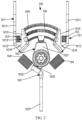
- FIG. 2 illustrates a front view of the contact assembly 100, in which a moveable contact 102 in at an opening position
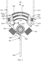
- FIG. 3 illustrates a front view of the contact assembly 100, in which the moveable contact 102 in a closing position (hereinafter also referred to as a first closing position or a second closing position).
- the contact assembly 100 includes a pair of power supply side static contacts 101, a moveable contact 102, a blowing arc block 103, and a pair of magnetic conductive blocks 104.
- the contact assembly 100 may further include a load side static contact 105.
- the pair of power supply side static contacts 101 are coupled to a first power supply (e. g., a primary power supply) or a second power supply (e.g., a backup power supply), to allow the switching device to switch between the primary power supply and the backup power supply.
- FIG. 4 illustrates a perspective view of one of the power supply side static contacts 101. As shown in FIG.
- the power supply side static contact 101 generally has a bent structure, and generally includes three segments, which are respectively: a connection segment 1011 adapted to be coupled to the first power supply or the second power supply, a bent segment 1012 bent from an end of the connection segment 1011 (an end far away from coupling of the first power supply or the second power supply), and a coupling segment 1013.
- An angle between the bent segment 1012 and the connection segment 1011 may be greater than 90 degrees and less than 180 degrees, for example, an angle between 120 degrees and 160 degrees.
- the coupling segment 1013 extends from the bent segment 1012 in a thickness direction perpendicular to the bent segment 1012.
- the coupling segment 1013 may include a pair of coupling arms arranged to be spaced apart by a predetermined distance in a width direction of the connection segment 1011.
- Each coupling arm includes a coupling portion 1014 extending from the bent segment 1012 and a lead-in portion 1015 extending from an end of the coupling portion 1014 at a predetermined angle with respect to the coupling portion 1014.
- the predetermined angle may be, for example, any suitable angle between 90 degrees and 180 degrees to make distances between the lead-in portion 1015 and the connection segment 1011 of the pair of coupling arms 1054 are equal.
- the lead-in portion 1015 may be triangular in shape, and an edge of the lead-in portion 1015 that is close to the connection segment 1011 is parallel to the connection segment 1011 and spaced apart from the connection segment 1011 by a predetermined distance.
- the edge of the lead-in portion 1015 away from the connection segment 1011 gradually approaches the connection segment 1011 in an extending direction from the coupling portion 1014 to a tail end of the lead-in portion 1015, and forms an acute angle at the tail end of the lead-in portion 1015 with the edge of the lead-in portion 1015 that is close to the connection segment 1011, thereby forming an arc guiding angle.
- the lead-in portion 1015 has a structure extending toward the connection segment 1011 as a whole, so that an opening distance can be enlarged, an arc can be elongated, and arc extinguishing can be facilitated.
- the edge of the lead-in portion 1015 away from the connection segment 1011 may be provided with a chamfer structure to facilitate coupling between the movable contact 102 and the power supply side static contact 101.
- an arc extinguishing chamber 106 may be further disposed between the pair of power supply side static contacts 101.
- the arc extinguishing chamber 106 is arranged between the coupling segments 1013 of the pair of power supply side static contacts 101 and includes grid plates 1061 spaced apart by a predetermined distance.
- the plurality of grid plates 1061 may also be arranged in an arc-shaped manner, and there is a non-zero angle between two adjacent grid plates 1061, so that the plurality of grid plates 1061 can transition evenly between the lead-in portions 1015 of the coupling segments 1013 of two power supply side static contacts 101, thereby facilitating effective arc extinguishing.
- the moveable contact 102 of the contact assembly 100 can be driven to rotate around a rotational axis A to switch between a first closing position, a second closing position, and an opening position between the first closing position and the second closing position.
- the movable contact 102 In the first closing position, the movable contact 102 is coupled to the coupling segment 1013 of the power supply side static contact 101 coupled to the first power supply to connect the first power supply to a loop of the load.
- the movable contact 102 is coupled to the coupling segment 1013 of the power supply side static contact 101 coupled to the second power supply to connect the second power supply to the loop of the load.
- the movable contact 102 is separated from the coupling segment 1013 of the pair of power supply side static contacts 101.
- the movable contact 102 may include a bracket 1021 and two pairs of movable contact plates 1022.
- the bracket 1021 may be made of non-conductive materials.
- Each pair of the movable contact plates 1022 are arranged partially in the bracket 1021 at a predetermined distance apart.
- each pair of movable contact plates 1022 clamp one of the pair of coupling arms of the corresponding power supply side static contact 101, thereby implementing coupling between the movable contact 102 and the power supply side static contact 101.
- connection segment 1011 the bent segment 1012, the coupling segment 1013, and the movable contact 102 to the load via an arc is formed.
- a loop current is divided into several segments, in which a Lorentz force for the arc of a magnetic field generated by a current passing through an lead-in part 1015 and from the coupling portion 1014 of the coupling segment 1013 to a movable contact 102 is upward (i.e., facilitating it to enter the arc extinguishing chamber 106), and a Lorentz force for the arc of a magnetic field generated by a current passing through a bent segment 1012 and from a connection segment 1011 is downward (preventing it from entering the arc extinguishing chamber 106).
- a tail end of the connection segment 1011 is far away from an arc formed between the bent segment 1012 and the movable contact 102 and the power supply side static contact 101, and has no obvious effect on the arc.
- a magnetic field near an end of the connection segment 1011 close to the bent segment 1012 has strong resistance to the arc. Therefore, referring back to FIGS. 2 and 3 , in order to facilitate entry of the arc into the arc extinguishing chamber 106, an blowing arc block 103 is provided at the end of the connection segment 1011 adjacent to the bent segment 1012, and the blowing arc block 103 is located between the connection segment 1011 and the lead-in portion 1015 of the coupling segment 1013 and is magnetic. In this way, the blowing arc block 103 can shield most of a magnetic field generated by a current near the end of the connection segment 1011 adjacent to the bent segment 1012, thereby effectively reducing a blocking effect of the current at this position on the arc.
- the blowing arc block 103 is arranged to align with a lower half of the lead-in portion 1015 adjacent the coupling portion 1014. That is, a size of the blowing arc block 103 in the extending direction of the connection segment 1011 is substantially only half of a length of the lead-in portion 1015 in this direction.
- a pair of magnetic conductive blocks 104 are arranged adjacent to the movable contact 102 in the first closing position and second closing position and are magnetic.
- the magnetic conductive block 104 is arranged as close as possible to the movable contact 102 without contacting each other, that is to say, a minimum distance between the magnetic conductive block 104 and the movable contact 102 is less than a predetermined threshold but not zero.
- the magnetic conductive block 104 may be fixed in vicinity of the movable contact 102 by a non-conductive fixing member, whereby the magnetic conductive block 104 and the movable contact 102 are separated by a predetermined distance by the fixing member and a wall of the bracket 1021.
- FIG. 5 illustrates a perspective view of the load side static contact 105 mentioned above.
- the load side static contact 105 includes a first segment 1053 and a second segment coupled to a load.
- the first segment 1053 is partially inserted into the bracket 1021 of the movable contact 102 to couple with the movable contact 102, as shown in FIG. 6 .
- the second segment includes a first end 1051 coupled to the load and a second end 1052 opposite the first end 1051.
- the second end 1052 is bent with a predetermined angle relative to other portions of the second segment, and the predetermined angle is in a range of 95 degrees to 175 degrees.
- the first segment 1053 is generally U-shaped and includes a pair of first arms extending from the second end 1052 of the second segment in a thickness direction of the second segment (i.e., a direction perpendicular to the second segment). Each of the pair of first arms is inserted between the corresponding pair of movable contact plates 1022 to be coupled to the movable contact 102, as shown in FIG. 7 .
- the load side static contact 105 generally adopts an asymmetric structure.
- the magnetic conductive block 104 on a side (for example, a left side in FIGS. 2 and 3 ) of the second end 1052 may have a larger size than the magnetic conductive block 104 on the other side to further optimize the short-circuit resistance performance of the switching device.
- the load side static contacts 105 may also employ other structures than shown in FIG. 5 .
- the second segment of the load side static contact 105 may extend from a middle portion of a bottom wall of the first segment 1053 with the U-shape towards an opposite direction of the first arm perpendicular to the bottom wall.
- the load side static contacts 105 generally form a symmetrical fork-type structure.
- a thickness of the first arm may be less than a thickness of the second segment.
- the thickness of the first arm may be in a range of 7 mm to 9 mm, such as 8 mm, and the thickness of the second segment may be in the range of 9 mm to 11 mm, such as 10 mm.
- the thickness of the first arm may also be equal to the thickness of the second segment.
- the load side static contact 105 may be integrally formed, for example, by a stamping process or any other suitable process. In this way, a cost of parts can be effectively saved, and requirements for product temperature rise and the electrical performance of the switching device are ensured.
- a contact point C of the load side static contacts 105 and the movable contacts 102 is offset from the rotational axis A of the movable contacts 102 in a radial direction.
- the contact point C can rotate around the rotation center, which is equivalent to that the load side static contact 105 slides along an arc relative to the movable contact 102.
- This sliding design may ensure that the contact positions of the movable contact 102 and the load side static contact 105 always slide, thereby preventing a contact state of the contact from being affected by the contact position due to foreign matters, and ensuring reliability of the switching device.
Landscapes
- Physics & Mathematics (AREA)
- Electromagnetism (AREA)
- Arc-Extinguishing Devices That Are Switches (AREA)
Abstract
Description
- Example embodiments of the present disclosure relate generally to a field of electrical apparatuses, and more particularly, to a contact assembly for a switching device and a switching device.
- An automatic transfer switching device (ATS) is a key component for an emergency or backup power system. The automatic transfer switching device can automatically switch a load from a primary power supply to a standby power supply when the primary power supply fails, thereby ensuring continuous supply of power. The conventional dual power supply transfer switch has problems such as low short-circuit resistance performance and poor safety and reliability. In addition, there are still some dual power supply transfer switches have problems with temperature rise performance and electrical performance of the product that cannot be effectively ensured.
- In a first aspect of the present disclosure, a contact assembly for a switching device is provided. The contact assembly includes: a pair of power supply side static contacts each having a bent structure and including a connection segment coupled to a first power supply and a second power supply, a bent segment bent from an end of the connection segment, and a coupling segment, wherein the coupling segment extends from the bent segment in a thickness direction perpendicular to the bent segment; a movable contact adapted to rotate around a rotational axis to switch between a first closing position, a second closing position and an opening position between the first closing position and the second closing position, at the first closing position and the second closing position, the movable contact being respectively coupled to the coupling segments of the pair of power supply side static contacts, at the opening position, the movable contact being separated from coupling segments of a pair of power supply side static contacts; a blowing arc block arranged at an end of the connection segment adjacent to the bent segment and located between the connection segment and the coupling segment; and a pair of magnetic conductive blocks respectively arranged adjacent to the movable contact at the first closing position and second closing position, wherein a minimum distance between the magnetic conductive blocks and the movable contact is less than a predetermined threshold but not zero.
- In some embodiments, the coupling segment includes: a pair of coupling arms arranged to be spaced apart a predetermined distance in a width direction of the connection segment, each of the pair of coupling arms including a coupling portion extending from the bent segment and a lead-in portion extending from an end of the coupling portion at a predetermined angle with respect to the coupling portion.
- In some embodiments, at least a part of an edge of the lead-in portion that is close to the connection segment is parallel to the connection segment, and an edge of the lead-in portion away from the connection segment extends from the coupling portion towards the connection segment.
- In some embodiments, the movable contact includes: a bracket; and two pairs of movable contact plates, each pair of the two pairs of movable contact plates being arranged partially in the bracket at a predetermined distance apart, and in the first closing position or the second closing position, each pair of movable contact plates clamping one of the pair of coupling arms of the corresponding power supply side static contact.
- In some embodiments, the contact assembly further includes a load side static contact including a first segment and a second segment coupled to a load, wherein the first segment being partially inserted into the bracket to be coupled with the movable contact.
- In some embodiments, the second segment includes a first end coupled to the load and a second end opposite the first end and coupled to the first segment.
- In some embodiments, the first segment includes a pair of coupling arms extending from the second end of the second segment in a thickness direction of the second segment.
- In some embodiments, a thickness of the coupling arm is less than a thickness of the second segment.
- In some embodiments, a contact point between the load side static contact and the movable contact is offset from the rotational axis of the movable contact in a radial direction.
- In some embodiments, the load side static contact is integrally formed.
- In some embodiments, the blowing arc block is arranged to be aligned with a lower half of the lead-in portion adjacent the coupling portion.
- In some embodiments, the contact assembly further includes an arc extinguishing chamber arranged between the coupling segments of the pair of power supply side static contacts, and including a plurality of grid plates spaced apart by a predetermined distance.
- In some embodiments, the blowing arc block and the magnetic conductive block are magnetic.
- According to a second aspect of the embodiments of the present disclosure, a switching device is provided. The switching device includes: a housing; and the contact assembly of the first aspect of the embodiments of the present disclosure, which partially arranged in the housing.
- According to the embodiments of the present disclosure, by providing the magnetic conductive block and effectively controlling a size of the blowing arc block, an electric repulsive force acting on the movable contact when closing can be reduced, thereby significantly improving short-circuit resistance performance of the switching device.
- It should be appreciated that what is described in this Summary is not intended to limit critical features or essential features of embodiments of the present disclosure, nor is it intended to limit the scope of the present disclosure. Other features of the present disclosure will become readily appreciated from the following description.
- The above and other features, advantages, and aspects of various embodiments of the present disclosure will become more apparent with reference to the following detailed description taken in conjunction with the drawings. In the drawings, the same or similar reference signs denote the same or similar elements, wherein:
-
FIG. 1 illustrates a perspective schematic view of a contact assembly according to embodiments of the present disclosure; -
FIG. 2 illustrates a simplified schematic front view of a contact assembly according to embodiments of the present disclosure, in which a movable contact is at an opening position; -
FIG. 3 illustrates a simplified schematic front view of a contact assembly according to embodiments of the present disclosure, in which a movable contact is at a first closing position or a second closing position; -
FIG. 4 illustrates a perspective view of a power supply side static contact according to embodiments of the present disclosure; -
FIG. 5 illustrates a perspective view of a load side static contact according to embodiments of the present disclosure; -
FIG. 6 illustrates a schematic perspective view of a load side static contact according to embodiments of the present disclosure; -
FIG. 7 illustrates a schematic view of connection of a load side static contact and a movable contact according to embodiments of the present disclosure. - Embodiments of the present disclosure will be described in more detail below with reference to the drawings. Although certain embodiments of the present disclosure are shown in the drawings, it should be understood that the present disclosure may be implemented in various forms and should not be construed as limited to the embodiments set forth herein, but rather, these embodiments are provided for a thorough and complete understanding of the present disclosure. It should be understood that the drawings and embodiments of the present disclosure are only for illustrative purposes and are not intended to limit a scope of the present disclosure.
- It should be noted that titles of any section/subsection provided herein are not limiting. Various embodiments are described throughout herein, and any type of embodiment can be included under any section/subsection. Furthermore, embodiments described in any section/subsection may be combined in any manner with any other embodiments described in the same section/subsection and/or different sections/subsections.
- In description of the embodiments of the present disclosure, the term "including" and the like should be understood as open-ended including, that is, "including but not limited to". The term "based on" should be read as "based at least in part on. " The term "one embodiment" or "the embodiment" should be read as "at least one embodiment. ". The term "some embodiments" should be understood as "at least some embodiments. " Other explicit and implicit definitions may also be included below. The terms "first", "second", etc. may refer to different or identical objects. Other explicit and implicit definitions may also be included below.
- In a conventional dual power supply transfer switch, during a closing process when a movable contact are driven by a mechanism towards a static contact on a side of a power supply, an electrodynamic direction of the movable contact is towards a direction of the contact opening. When the connected line includes a plurality of poles, each pole will have a corresponding closing process for the movable contact and the static contact. In this case, if the mechanism cannot withstand an electrodynamic repulsion force of quadrupole breaking, the movable contact will be opened, resulting in poor short circuit performance of the product.
- In addition, in some conventional solutions, the coupling point of a load side static contact and the movable contact is concentric with a rotation center of a contact bracket, and a position of a coupling point remains unchanged in the closing and opening process, thereby causing poor contact of the coupling point, and causing failure of some functions.
- To address or at least partially address the above described or other potential problems with conventional switching devices, embodiments of the present disclosure provide a contact assembly for a switching device and a corresponding switching device. A concept according to the present disclosure will be described below with reference to
FIGS. 1 to 7 . The switching device according to embodiments of the present disclosure may be a dual power supply transfer switch. For example, the switching device may be one pole of the dual power supply transfer switch. The dual power supply transfer switch may include a plurality of poles, each pole corresponding to one switching device. It should be understood that the switching device may also be other switching devices, and the concept of the present disclosure will be mainly described herein by taking the switching device being the dual power supply transfer switch as an example. It should be understood that, other switching devices with a similar structure are also similar, which will not be described in detail hereinafter. -
FIG. 1 illustrates a perspective view of acontact assembly 100 according to embodiments of the present disclosure,FIG. 2 illustrates a front view of thecontact assembly 100, in which amoveable contact 102 in at an opening position, andFIG. 3 illustrates a front view of thecontact assembly 100, in which themoveable contact 102 in a closing position (hereinafter also referred to as a first closing position or a second closing position). - As shown in
FIGS. 1 to 3 , in general, thecontact assembly 100 according to embodiments of the present disclosure includes a pair of power supply sidestatic contacts 101, amoveable contact 102, a blowingarc block 103, and a pair of magneticconductive blocks 104. As will also be mentioned below, thecontact assembly 100 may further include a load sidestatic contact 105. The pair of power supply sidestatic contacts 101 are coupled to a first power supply (e. g., a primary power supply) or a second power supply (e.g., a backup power supply), to allow the switching device to switch between the primary power supply and the backup power supply.FIG. 4 illustrates a perspective view of one of the power supply sidestatic contacts 101. As shown inFIG. 2 to 4 , the power supply sidestatic contact 101 generally has a bent structure, and generally includes three segments, which are respectively: aconnection segment 1011 adapted to be coupled to the first power supply or the second power supply, abent segment 1012 bent from an end of the connection segment 1011 (an end far away from coupling of the first power supply or the second power supply), and acoupling segment 1013. - An angle between the
bent segment 1012 and theconnection segment 1011 may be greater than 90 degrees and less than 180 degrees, for example, an angle between 120 degrees and 160 degrees. Thecoupling segment 1013 extends from thebent segment 1012 in a thickness direction perpendicular to thebent segment 1012. In some embodiments, as shown inFIG. 4 , thecoupling segment 1013 may include a pair of coupling arms arranged to be spaced apart by a predetermined distance in a width direction of theconnection segment 1011. Each coupling arm includes acoupling portion 1014 extending from thebent segment 1012 and a lead-inportion 1015 extending from an end of thecoupling portion 1014 at a predetermined angle with respect to thecoupling portion 1014. The predetermined angle may be, for example, any suitable angle between 90 degrees and 180 degrees to make distances between the lead-inportion 1015 and theconnection segment 1011 of the pair ofcoupling arms 1054 are equal. - In some embodiments, the lead-in
portion 1015 may be triangular in shape, and an edge of the lead-inportion 1015 that is close to theconnection segment 1011 is parallel to theconnection segment 1011 and spaced apart from theconnection segment 1011 by a predetermined distance. The edge of the lead-inportion 1015 away from theconnection segment 1011 gradually approaches theconnection segment 1011 in an extending direction from thecoupling portion 1014 to a tail end of the lead-inportion 1015, and forms an acute angle at the tail end of the lead-inportion 1015 with the edge of the lead-inportion 1015 that is close to theconnection segment 1011, thereby forming an arc guiding angle. In this manner, the lead-inportion 1015 has a structure extending toward theconnection segment 1011 as a whole, so that an opening distance can be enlarged, an arc can be elongated, and arc extinguishing can be facilitated. In some embodiments, the edge of the lead-inportion 1015 away from theconnection segment 1011 may be provided with a chamfer structure to facilitate coupling between themovable contact 102 and the power supply sidestatic contact 101. - Referring back to
FIGS. 1 to 3 , anarc extinguishing chamber 106 may be further disposed between the pair of power supply sidestatic contacts 101. For example, thearc extinguishing chamber 106 is arranged between thecoupling segments 1013 of the pair of power supply sidestatic contacts 101 and includesgrid plates 1061 spaced apart by a predetermined distance. Since the lead-inportions 1015 of thecoupling segments 1013 of the pair of power supply sidestatic contacts 101 are not parallel to each other, the plurality ofgrid plates 1061 may also be arranged in an arc-shaped manner, and there is a non-zero angle between twoadjacent grid plates 1061, so that the plurality ofgrid plates 1061 can transition evenly between the lead-inportions 1015 of thecoupling segments 1013 of two power supply sidestatic contacts 101, thereby facilitating effective arc extinguishing. - The
moveable contact 102 of thecontact assembly 100 can be driven to rotate around a rotational axis A to switch between a first closing position, a second closing position, and an opening position between the first closing position and the second closing position. In the first closing position, themovable contact 102 is coupled to thecoupling segment 1013 of the power supply sidestatic contact 101 coupled to the first power supply to connect the first power supply to a loop of the load. In the second closing position, themovable contact 102 is coupled to thecoupling segment 1013 of the power supply sidestatic contact 101 coupled to the second power supply to connect the second power supply to the loop of the load. At the opening position, themovable contact 102 is separated from thecoupling segment 1013 of the pair of power supply sidestatic contacts 101. - In some embodiments, as shown in
FIGS. 6 and 7 , themovable contact 102 may include abracket 1021 and two pairs ofmovable contact plates 1022. Thebracket 1021 may be made of non-conductive materials. Each pair of themovable contact plates 1022 are arranged partially in thebracket 1021 at a predetermined distance apart. When themovable contact 102 is in the first closing position or the second closing position, each pair ofmovable contact plates 1022 clamp one of the pair of coupling arms of the corresponding power supply sidestatic contact 101, thereby implementing coupling between themovable contact 102 and the power supply sidestatic contact 101. - At the moment when the power supply side
static contact 101 and themovable contact 102 are to be coupled, a current flowing from theconnection segment 1011, thebent segment 1012, thecoupling segment 1013, and themovable contact 102 to the load via an arc is formed. In order to facilitate understanding, a loop current is divided into several segments, in which a Lorentz force for the arc of a magnetic field generated by a current passing through an lead-inpart 1015 and from thecoupling portion 1014 of thecoupling segment 1013 to amovable contact 102 is upward (i.e., facilitating it to enter the arc extinguishing chamber 106), and a Lorentz force for the arc of a magnetic field generated by a current passing through abent segment 1012 and from aconnection segment 1011 is downward (preventing it from entering the arc extinguishing chamber 106). - A tail end of the
connection segment 1011 is far away from an arc formed between thebent segment 1012 and themovable contact 102 and the power supply sidestatic contact 101, and has no obvious effect on the arc. A magnetic field near an end of theconnection segment 1011 close to thebent segment 1012 has strong resistance to the arc. Therefore, referring back toFIGS. 2 and3 , in order to facilitate entry of the arc into thearc extinguishing chamber 106, an blowingarc block 103 is provided at the end of theconnection segment 1011 adjacent to thebent segment 1012, and the blowingarc block 103 is located between theconnection segment 1011 and the lead-inportion 1015 of thecoupling segment 1013 and is magnetic. In this way, the blowingarc block 103 can shield most of a magnetic field generated by a current near the end of theconnection segment 1011 adjacent to thebent segment 1012, thereby effectively reducing a blocking effect of the current at this position on the arc. - In some embodiments, the blowing
arc block 103 is arranged to align with a lower half of the lead-inportion 1015 adjacent thecoupling portion 1014. That is, a size of the blowingarc block 103 in the extending direction of theconnection segment 1011 is substantially only half of a length of the lead-inportion 1015 in this direction. - With continued reference to
FIGS. 2 and3 , a pair of magneticconductive blocks 104 are arranged adjacent to themovable contact 102 in the first closing position and second closing position and are magnetic. The magneticconductive block 104 is arranged as close as possible to themovable contact 102 without contacting each other, that is to say, a minimum distance between the magneticconductive block 104 and themovable contact 102 is less than a predetermined threshold but not zero. For example, the magneticconductive block 104 may be fixed in vicinity of themovable contact 102 by a non-conductive fixing member, whereby the magneticconductive block 104 and themovable contact 102 are separated by a predetermined distance by the fixing member and a wall of thebracket 1021. - In some embodiments, a single magnetically
conductive block 104 may be a complete block or a stacked sheet assembly. The magneticconductive block 104 may be in a regular shape as shown inFIGS. 2 and3 , and may also be in an irregular shape. By arranging the magneticconductive block 104 and effectively controlling the size of the blowingarc block 103, the electrodynamic repulsive force acting on themovable contact 102 when closing can be reduced, thereby significantly improving the short-circuit resistance performance of the switching device. -
FIG. 5 illustrates a perspective view of the load sidestatic contact 105 mentioned above. As shown inFIG. 5 , the load sidestatic contact 105 includes afirst segment 1053 and a second segment coupled to a load. Thefirst segment 1053 is partially inserted into thebracket 1021 of themovable contact 102 to couple with themovable contact 102, as shown inFIG. 6 . The second segment includes afirst end 1051 coupled to the load and asecond end 1052 opposite thefirst end 1051. Thesecond end 1052 is bent with a predetermined angle relative to other portions of the second segment, and the predetermined angle is in a range of 95 degrees to 175 degrees. - In some embodiments, the
first segment 1053 is generally U-shaped and includes a pair of first arms extending from thesecond end 1052 of the second segment in a thickness direction of the second segment (i.e., a direction perpendicular to the second segment). Each of the pair of first arms is inserted between the corresponding pair ofmovable contact plates 1022 to be coupled to themovable contact 102, as shown inFIG. 7 . - As shown in
FIG. 5 , the load sidestatic contact 105 generally adopts an asymmetric structure. In this case, the magneticconductive block 104 on a side (for example, a left side inFIGS. 2 and3 ) of thesecond end 1052 may have a larger size than the magneticconductive block 104 on the other side to further optimize the short-circuit resistance performance of the switching device. - In some embodiments, the load side
static contacts 105 may also employ other structures than shown inFIG. 5 . For example, in some embodiments, the second segment of the load sidestatic contact 105 may extend from a middle portion of a bottom wall of thefirst segment 1053 with the U-shape towards an opposite direction of the first arm perpendicular to the bottom wall. In this case, the load sidestatic contacts 105 generally form a symmetrical fork-type structure. - In some embodiments, a thickness of the first arm may be less than a thickness of the second segment. For example, in some embodiments, the thickness of the first arm may be in a range of 7 mm to 9 mm, such as 8 mm, and the thickness of the second segment may be in the range of 9 mm to 11 mm, such as 10 mm. In some embodiments, the thickness of the first arm may also be equal to the thickness of the second segment. In addition, the load side
static contact 105 may be integrally formed, for example, by a stamping process or any other suitable process. In this way, a cost of parts can be effectively saved, and requirements for product temperature rise and the electrical performance of the switching device are ensured. - In some embodiments, as shown in
FIG. 7 , a contact point C of the load sidestatic contacts 105 and the movable contacts 102 (i.e., the contact point C of the first arm inserted between the corresponding pair of movable contact plates 1022) is offset from the rotational axis A of themovable contacts 102 in a radial direction. In this way, during rotation of themovable contact 102 around the rotation axis A, the contact point C can rotate around the rotation center, which is equivalent to that the load sidestatic contact 105 slides along an arc relative to themovable contact 102. This sliding design may ensure that the contact positions of themovable contact 102 and the load sidestatic contact 105 always slide, thereby preventing a contact state of the contact from being affected by the contact position due to foreign matters, and ensuring reliability of the switching device. - Having described implementations of the present disclosure above, the foregoing description is exemplary, not exhaustive, and is not limited to the implementations disclosed. Many modifications and variations will be apparent to those of ordinary skill in the art without departing from the scope and spirit of the implementations described. Choice of terms used herein is intended to best explain the principles of the implementations, practical application, or improvements to technologies in the marketplace, or to enable others of ordinary skill in the art to understand the implementations disclosed herein.
Claims (14)
- A contact assembly for a switching device, comprising:a pair of power supply side static contacts (101) each having a bent structure and comprising a connection segment (1011) coupled to a first power supply and a second power supply, a bent segment (1012) bent from an end of the connection segment (1011), and a coupling segment (1013), wherein the coupling segment (1013) extends from the bent segment (1012) in a thickness direction perpendicular to the bent segment (1012);a movable contact (102) adapted to rotate around a rotational axis (A) to switch between a first closing position, a second closing position, and an opening position between the first closing position and the second closing position, at the first closing position and the second closing position, the movable contact (102) being respectively coupled to the coupling segments (1013) of the pair of power supply side static contacts (101), at the opening position, the movable contact (102) being separated from the coupling segments (1013) of the pair of power supply side static contacts (101);a blowing arc block (103) arranged at an end of the connection segment (1011) adjacent to the bent segment (1012) and located between the connection segment (1011) and the coupling segment (1013); anda pair of magnetic conductive blocks (104) respectively arranged adjacent to the movable contact (102) at the first closing position and the second closing position, wherein a minimum distance between the magnetic conductive blocks (104) and the movable contact (102) is less than a predetermined threshold but not zero.
- The contact assembly of claim 1, wherein the coupling segment (1013) comprises:
a pair of coupling arms arranged to be spaced apart by a predetermined distance in a width direction of the connection segment (1011), each of the pair of coupling arms comprising a coupling portion (1014) extending from the bent segment (1012) and a lead-in portion (1015) extending from an end of the coupling portion (1014) at a predetermined angle with respect to the coupling portion (1014). - The contact assembly of claim 2, wherein at least a part of an edge of the lead-in portion (1015) that is close to the connection segment (1011) is parallel to the connection segment (1011), and
an edge of the lead-in portion (1015) away from the connection segment (1011) extends from the coupling portion (1014) towards the connection segment (1011). - The contact assembly of any of claims 1-3, wherein the movable contact (102) comprises:a bracket (1021); andtwo pairs of movable contact plates (1022), each pair of the two pairs of movable contact plates (1022) being arranged partially in the bracket (1021) at a predetermined distance apart, and in the first closing position or the second closing position, each pair of movable contact plates (1022) clamping one of the pair of coupling arms of the corresponding power supply side static contact (101).
- The contact assembly of claim 4, further comprising:
a load side static contact (105) comprising a first segment (1053) and a second segment coupled to a load, wherein the first segment (1053) being partially inserted into the bracket (1021) to be coupled with the movable contact (102). - The contact assembly of claim 5, wherein the second segment comprises a first end (1051) coupled to the load and a second end (1052) opposite the first end (1051) and coupled to the first segment (1053).
- The contact assembly of claim 6, wherein the first segment (1053) comprises a pair of coupling arms (1054) extending from the second end (1052) of the second segment in a thickness direction of the second segment.
- The contact assembly of claim 7, wherein a thickness of the coupling arm (1054) is less than a thickness of the second segment.
- The contact assembly of any of claims 5-8, wherein a contact point (C) between the load side static contact (105) and the movable contact (102) is offset from the rotational axis (A) of the movable contact (102) in a radial direction.
- The contact assembly of any of claims 5-8, wherein the load side static contact (105) is integrally formed.
- The contact assembly of any of claims 1-3 and 5-8, wherein the blowing arc block (103) is arranged to be aligned with a lower half of the lead-in portion (1015) adjacent to the coupling portion (1014).
- The contact assembly of any of claims 1-3 and 5-8, further comprising:
an arc extinguishing chamber (106) arranged between the coupling segments (1013) of the pair of power supply side static contacts (101), and comprising a plurality of grid plates (1061) spaced apart by a predetermined distance. - The contact assembly of any of claims 1-3 and 5-8, wherein the blowing arc block (103) and the magnetic conductive block (104) are magnetic.
- A switching device comprising:a housing; andthe contact assembly of any of claims 1-13, which partially arranged in the housing.
Applications Claiming Priority (1)
| Application Number | Priority Date | Filing Date | Title |
|---|---|---|---|
| CN202410016829.4A CN120261200A (en) | 2024-01-04 | 2024-01-04 | Contact assembly for switch device and switch device |
Publications (1)
| Publication Number | Publication Date |
|---|---|
| EP4583134A1 true EP4583134A1 (en) | 2025-07-09 |
Family
ID=94283910
Family Applications (1)
| Application Number | Title | Priority Date | Filing Date |
|---|---|---|---|
| EP24307126.3A Pending EP4583134A1 (en) | 2024-01-04 | 2024-12-17 | Contact assembly for switching apparatus and switching apparatus |
Country Status (2)
| Country | Link |
|---|---|
| EP (1) | EP4583134A1 (en) |
| CN (1) | CN120261200A (en) |
Citations (3)
| Publication number | Priority date | Publication date | Assignee | Title |
|---|---|---|---|---|
| CH330629A (en) * | 1954-03-10 | 1958-06-15 | Siemens Ag | Electrical switch with upstream and main contact points, especially lever switches |
| EP4246546A1 (en) * | 2022-03-17 | 2023-09-20 | Schneider Electric Industries SAS | Automatic transfer switch and contact system for automatic transfer switch |
| EP4258306A1 (en) * | 2022-04-08 | 2023-10-11 | Schneider Electric Industries Sas | A switching system |
-
2024
- 2024-01-04 CN CN202410016829.4A patent/CN120261200A/en active Pending
- 2024-12-17 EP EP24307126.3A patent/EP4583134A1/en active Pending
Patent Citations (3)
| Publication number | Priority date | Publication date | Assignee | Title |
|---|---|---|---|---|
| CH330629A (en) * | 1954-03-10 | 1958-06-15 | Siemens Ag | Electrical switch with upstream and main contact points, especially lever switches |
| EP4246546A1 (en) * | 2022-03-17 | 2023-09-20 | Schneider Electric Industries SAS | Automatic transfer switch and contact system for automatic transfer switch |
| EP4258306A1 (en) * | 2022-04-08 | 2023-10-11 | Schneider Electric Industries Sas | A switching system |
Also Published As
| Publication number | Publication date |
|---|---|
| CN120261200A (en) | 2025-07-04 |
Similar Documents
| Publication | Publication Date | Title |
|---|---|---|
| US9281138B2 (en) | Parallel type transfer switch contacts assemblies | |
| US12431312B2 (en) | Operating mechanism of circuit breaker | |
| CN107230570B (en) | Electrical switching apparatus and arc chute assembly and related circuit protection method | |
| US20200411259A1 (en) | Circuit breaker for isolating an electrical circuit | |
| CN105762038B (en) | Breaker contact system and breaker | |
| CN110998771B (en) | Electrical switchgear and its debris barrier | |
| JPS58147979A (en) | Terminal connector | |
| EP1681693B1 (en) | Monolithic stationary conductor and current limiting power switch incorporating same | |
| CN109478475B (en) | High-voltage electrical disconnect device with magnetic arc deflection assembly | |
| WO2018130209A1 (en) | High power and high insulation performance relay for solar photovoltaic inverter | |
| WO2022252820A1 (en) | Electric switch having multiple superimposed suction forces | |
| JP2709251B2 (en) | Draw-out type circuit breaker | |
| WO2025140151A1 (en) | Arc extinguishing structure of circuit breaker, and circuit breaker | |
| CN218447618U (en) | Transfer switch device and dual power transfer switch device | |
| CN120261200A (en) | Contact assembly for switch device and switch device | |
| KR102353017B1 (en) | Direct Current Circuit Breaker | |
| EP3772078B1 (en) | An electrode for a circuit breaker and the circuit breaker | |
| EP0482197B1 (en) | Circuit breaker | |
| CN221573840U (en) | Breaking unit and circuit breaker | |
| CA2894939C (en) | Electrical switching apparatus and link assembly therefor | |
| JPH07211179A (en) | Arc extinguishing device | |
| KR101912698B1 (en) | Circuit breaker having operating device | |
| KR20210114263A (en) | Direct Current Circuit Breaker | |
| CN115458348B (en) | Change-over switch device and double-power supply change-over switch device | |
| KR102612860B1 (en) | Direct Current Circuit Breaker |
Legal Events
| Date | Code | Title | Description |
|---|---|---|---|
| PUAI | Public reference made under article 153(3) epc to a published international application that has entered the european phase |
Free format text: ORIGINAL CODE: 0009012 |
|
| STAA | Information on the status of an ep patent application or granted ep patent |
Free format text: STATUS: THE APPLICATION HAS BEEN PUBLISHED |
|
| AK | Designated contracting states |
Kind code of ref document: A1 Designated state(s): AL AT BE BG CH CY CZ DE DK EE ES FI FR GB GR HR HU IE IS IT LI LT LU LV MC ME MK MT NL NO PL PT RO RS SE SI SK SM TR |
|
| STAA | Information on the status of an ep patent application or granted ep patent |
Free format text: STATUS: REQUEST FOR EXAMINATION WAS MADE |
|
| 17P | Request for examination filed |
Effective date: 20251215 |
|
| GRAP | Despatch of communication of intention to grant a patent |
Free format text: ORIGINAL CODE: EPIDOSNIGR1 |
|
| STAA | Information on the status of an ep patent application or granted ep patent |
Free format text: STATUS: GRANT OF PATENT IS INTENDED |
|
| RIC1 | Information provided on ipc code assigned before grant |
Ipc: H01H 1/42 20060101AFI20260408BHEP Ipc: H01H 9/44 20060101ALI20260408BHEP Ipc: H01H 19/38 20060101ALI20260408BHEP |