EP4583082A1 - Display device - Google Patents
Display device Download PDFInfo
- Publication number
- EP4583082A1 EP4583082A1 EP23860752.7A EP23860752A EP4583082A1 EP 4583082 A1 EP4583082 A1 EP 4583082A1 EP 23860752 A EP23860752 A EP 23860752A EP 4583082 A1 EP4583082 A1 EP 4583082A1
- Authority
- EP
- European Patent Office
- Prior art keywords
- layer
- display device
- fiber
- fiber yarn
- base resin
- Prior art date
- Legal status (The legal status is an assumption and is not a legal conclusion. Google has not performed a legal analysis and makes no representation as to the accuracy of the status listed.)
- Pending
Links
Images







Classifications
-
- H—ELECTRICITY
- H05—ELECTRIC TECHNIQUES NOT OTHERWISE PROVIDED FOR
- H05K—PRINTED CIRCUITS; CASINGS OR CONSTRUCTIONAL DETAILS OF ELECTRIC APPARATUS; MANUFACTURE OF ASSEMBLAGES OF ELECTRICAL COMPONENTS
- H05K5/00—Casings, cabinets or drawers for electric apparatus
- H05K5/02—Details
-
- G—PHYSICS
- G06—COMPUTING OR CALCULATING; COUNTING
- G06F—ELECTRIC DIGITAL DATA PROCESSING
- G06F1/00—Details not covered by groups G06F3/00 - G06F13/00 and G06F21/00
- G06F1/16—Constructional details or arrangements
- G06F1/1613—Constructional details or arrangements for portable computers
- G06F1/1633—Constructional details or arrangements of portable computers not specific to the type of enclosures covered by groups G06F1/1615 - G06F1/1626
- G06F1/1637—Details related to the display arrangement, including those related to the mounting of the display in the housing
- G06F1/1652—Details related to the display arrangement, including those related to the mounting of the display in the housing the display being flexible, e.g. mimicking a sheet of paper, or rollable
-
- G—PHYSICS
- G09—EDUCATION; CRYPTOGRAPHY; DISPLAY; ADVERTISING; SEALS
- G09F—DISPLAYING; ADVERTISING; SIGNS; LABELS OR NAME-PLATES; SEALS
- G09F9/00—Indicating arrangements for variable information in which the information is built-up on a support by selection or combination of individual elements
- G09F9/30—Indicating arrangements for variable information in which the information is built-up on a support by selection or combination of individual elements in which the desired character or characters are formed by combining individual elements
- G09F9/301—Indicating arrangements for variable information in which the information is built-up on a support by selection or combination of individual elements in which the desired character or characters are formed by combining individual elements flexible foldable or roll-able electronic displays, e.g. thin LCD, OLED
-
- H—ELECTRICITY
- H10—SEMICONDUCTOR DEVICES; ELECTRIC SOLID-STATE DEVICES NOT OTHERWISE PROVIDED FOR
- H10K—ORGANIC ELECTRIC SOLID-STATE DEVICES
- H10K59/00—Integrated devices, or assemblies of multiple devices, comprising at least one organic light-emitting element covered by group H10K50/00
- H10K59/80—Constructional details
- H10K59/87—Passivation; Containers; Encapsulations
-
- D—TEXTILES; PAPER
- D02—YARNS; MECHANICAL FINISHING OF YARNS OR ROPES; WARPING OR BEAMING
- D02G—CRIMPING OR CURLING FIBRES, FILAMENTS, THREADS, OR YARNS; YARNS OR THREADS
- D02G3/00—Yarns or threads, e.g. fancy yarns; Processes or apparatus for the production thereof, not otherwise provided for
- D02G3/44—Yarns or threads characterised by the purpose for which they are designed
- D02G3/447—Yarns or threads for specific use in general industrial applications, e.g. as filters or reinforcement
-
- G—PHYSICS
- G06—COMPUTING OR CALCULATING; COUNTING
- G06F—ELECTRIC DIGITAL DATA PROCESSING
- G06F1/00—Details not covered by groups G06F3/00 - G06F13/00 and G06F21/00
- G06F1/16—Constructional details or arrangements
- G06F1/1613—Constructional details or arrangements for portable computers
- G06F1/1633—Constructional details or arrangements of portable computers not specific to the type of enclosures covered by groups G06F1/1615 - G06F1/1626
- G06F1/1637—Details related to the display arrangement, including those related to the mounting of the display in the housing
- G06F1/1641—Details related to the display arrangement, including those related to the mounting of the display in the housing the display being formed by a plurality of foldable display components
-
- G—PHYSICS
- G09—EDUCATION; CRYPTOGRAPHY; DISPLAY; ADVERTISING; SEALS
- G09F—DISPLAYING; ADVERTISING; SIGNS; LABELS OR NAME-PLATES; SEALS
- G09F9/00—Indicating arrangements for variable information in which the information is built-up on a support by selection or combination of individual elements
- G09F9/30—Indicating arrangements for variable information in which the information is built-up on a support by selection or combination of individual elements in which the desired character or characters are formed by combining individual elements
- G09F9/33—Indicating arrangements for variable information in which the information is built-up on a support by selection or combination of individual elements in which the desired character or characters are formed by combining individual elements being semiconductor devices, e.g. diodes
- G09F9/335—Indicating arrangements for variable information in which the information is built-up on a support by selection or combination of individual elements in which the desired character or characters are formed by combining individual elements being semiconductor devices, e.g. diodes being organic light emitting diodes [OLED]
-
- G—PHYSICS
- G09—EDUCATION; CRYPTOGRAPHY; DISPLAY; ADVERTISING; SEALS
- G09F—DISPLAYING; ADVERTISING; SIGNS; LABELS OR NAME-PLATES; SEALS
- G09F9/00—Indicating arrangements for variable information in which the information is built-up on a support by selection or combination of individual elements
- G09F9/30—Indicating arrangements for variable information in which the information is built-up on a support by selection or combination of individual elements in which the desired character or characters are formed by combining individual elements
- G09F9/35—Indicating arrangements for variable information in which the information is built-up on a support by selection or combination of individual elements in which the desired character or characters are formed by combining individual elements being liquid crystals
-
- H—ELECTRICITY
- H04—ELECTRIC COMMUNICATION TECHNIQUE
- H04M—TELEPHONIC COMMUNICATION
- H04M1/00—Substation equipment, e.g. for use by subscribers
- H04M1/02—Constructional features of telephone sets
- H04M1/0202—Portable telephone sets, e.g. cordless phones, mobile phones or bar type handsets
- H04M1/0206—Portable telephones comprising a plurality of mechanically joined movable body parts, e.g. hinged housings
- H04M1/0208—Portable telephones comprising a plurality of mechanically joined movable body parts, e.g. hinged housings characterized by the relative motions of the body parts
- H04M1/0214—Foldable telephones, i.e. with body parts pivoting to an open position around an axis parallel to the plane they define in closed position
-
- H—ELECTRICITY
- H04—ELECTRIC COMMUNICATION TECHNIQUE
- H04M—TELEPHONIC COMMUNICATION
- H04M1/00—Substation equipment, e.g. for use by subscribers
- H04M1/02—Constructional features of telephone sets
- H04M1/0202—Portable telephone sets, e.g. cordless phones, mobile phones or bar type handsets
- H04M1/026—Details of the structure or mounting of specific components
- H04M1/0266—Details of the structure or mounting of specific components for a display module assembly
- H04M1/0268—Details of the structure or mounting of specific components for a display module assembly including a flexible display panel
-
- H—ELECTRICITY
- H10—SEMICONDUCTOR DEVICES; ELECTRIC SOLID-STATE DEVICES NOT OTHERWISE PROVIDED FOR
- H10K—ORGANIC ELECTRIC SOLID-STATE DEVICES
- H10K77/00—Constructional details of devices covered by this subclass and not covered by groups H10K10/80, H10K30/80, H10K50/80 or H10K59/80
- H10K77/10—Substrates, e.g. flexible substrates
- H10K77/111—Flexible substrates
-
- D—TEXTILES; PAPER
- D10—INDEXING SCHEME ASSOCIATED WITH SUBLASSES OF SECTION D, RELATING TO TEXTILES
- D10B—INDEXING SCHEME ASSOCIATED WITH SUBLASSES OF SECTION D, RELATING TO TEXTILES
- D10B2401/00—Physical properties
- D10B2401/06—Load-responsive characteristics
- D10B2401/063—Load-responsive characteristics high strength
-
- D—TEXTILES; PAPER
- D10—INDEXING SCHEME ASSOCIATED WITH SUBLASSES OF SECTION D, RELATING TO TEXTILES
- D10B—INDEXING SCHEME ASSOCIATED WITH SUBLASSES OF SECTION D, RELATING TO TEXTILES
- D10B2505/00—Industrial
- D10B2505/02—Reinforcing materials; Prepregs
-
- H—ELECTRICITY
- H10—SEMICONDUCTOR DEVICES; ELECTRIC SOLID-STATE DEVICES NOT OTHERWISE PROVIDED FOR
- H10K—ORGANIC ELECTRIC SOLID-STATE DEVICES
- H10K2102/00—Constructional details relating to the organic devices covered by this subclass
- H10K2102/301—Details of OLEDs
- H10K2102/311—Flexible OLED
Definitions
- the flexible display may extend or reduce a display screen, for example, fold, bend, or slide the display screen, thereby significantly contributing to a decrease in volume or a change in design of the display device.
- the polarizing member POL may prevent external light incident on the display panel PNL from being reflected.
- the polarizing member POL may be attached to the window member WM through the first adhesive member PSA1 as a medium.
- a display panel PNL may be disposed on a bottom surface of the polarizing member POL.
- the buffer layer absorbs the external shock to prevent the display panel PNL from being damaged.
- the buffer layer may be formed as a single layer or a plurality of layers.
- the buffer layer may be formed of a polymer resin such as polyurethane, polycarbonate, polypropylene, or polyethylene or may include a material having elasticity, such as a sponge formed by foaming rubber, a urethane-based material, or an acrylic-based material.
- the heat dissipation layer may include a first heat dissipation layer including graphite or carbon nano-tube, and a second heat dissipation layer formed of a thin metal film such as copper, nickel, ferrite, or silver that may shield electromagnetic waves and has excellent thermal conductivity.
- the panel support 100 may serve to support the bottom surface of the display panel PNL.
- the panel support 100 may be disposed on the other surface (hereinafter, referred to as a 'bottom surface') of the barrier member BAR in the third direction DR3.
- the panel support 100 may be a rigid member whose shape or volume is not easily changed by external pressure.
- a grid pattern for easily bending the panel support 100 may be formed on the bending portion BP of the panel support 100.
- the panel support 100 may be carbon fiber reinforced plastic (CFRP) including carbon fibers, but is not limited thereto.
- CFRP carbon fiber reinforced plastic
- the panel support 100 may also be glass fiber reinforced plastic (GFRP) including glass fibers, or aramid fiber reinforced plastic (AFRP).
- GFRP glass fiber reinforced plastic
- AFRP aramid fiber reinforced plastic
- the panel support 100 is carbon fiber reinforced plastic. The structure of the panel support 100 will be described later in detail with reference to FIGS. 4 to 6 .
- the lower visibility preventing member TPU may be disposed on a bottom surface of the grid pattern formed on the bending portion BP of the panel support 100.
- the lower visibility preventing member TPU may prevent the grid pattern of the panel support 100 from being visually recognized to the outside.
- the lower visibility preventing member TPU may include a flexible material to reduce folding stress of the display device 1.
- the metal support MP may be disposed on a bottom surface of each of the first planarization portion PP1 and the second planarization portion PP2 of the panel support 100.
- the metal support MP may serve to support the bottom surface of each of the first planarization portion PP1 and the second planarization portion PP2 of the panel support 100 and absorb heat generated from the display panel PNL.
- the metal support MP may include copper (Cu), but is not limited thereto.
- the metal support MP may not be disposed on the bending portion BP to reduce the folding stress of the display device 1.
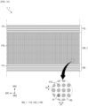
- FIG. 4 is a plan view schematically illustrating a panel support of the display device according to an example embodiment.
- the first planarization portion PP1 and the second planarization portion PP2 of the panel support 100 may be portions that are not bent.
- the first planarization portion PP1 may be disposed on the other side of the panel support 100 in the second direction DR2 as a portion of the panel support 100.
- the second planarization portion PP2 may be disposed on one side of the panel support 100 in the second direction DR2 as a portion of the panel support 100.
- the bending portion BP of the panel support 100 may be disposed between the first planarization portion PP1 and the second planarization portion PP2. That is, the second planarization portion PP2 may be disposed on one side of the bending portion BP in the second direction DR2, and the first planarization portion PP1 may be disposed on the other side of the bending portion BP in the second direction DR2.
- the bending portion BP of the panel support 100 may be a bendable area.
- a grid pattern including a plurality of slits SL penetrating through the panel support 100 in the third direction DR3 may be formed on the bending portion BP.
- the plurality of slits SL are a plurality of columns arranged in the first direction DR1, and may have a shape in which each column is arranged in the second direction DR2. Accordingly, the bending portion BP of the panel support 100 may be easily bent.
- FIG. 5 is a cross-sectional view schematically illustrating a cross section taken along line X1-X1' of FIG. 4 .
- FIG. 6 is a cross-sectional view schematically illustrating a cross section taken along line X2-X2' of FIG. 4 .
- the panel support 100 may be fiber reinforced plastic including fiber yarns and a base resin RS.
- the fiber yarns may be dispersed in the base resin RS.
- the fiber yarn may include graphene as a carbon fiber containing carbon
- the base resin RS may be an epoxy-based resin, a polyester-based resin, a polyamide-based resin, a polycarbonate-based resin, a polypropylene-based resin, a polybutylene-based resin, a polyacrylate-based resin, or a vinyl ester-based resin.
- the panel support 100 may include the first layer 110, the second layer 130, and the third layer 150 sequentially arranged in the other side in the third direction DR3.
- the first layer 110 of the panel support 100 may be adjacent to the barrier member BAR (see FIG. 3 ) disposed on an upper side of the panel support 100
- the third layer 150 thereof may be adjacent to the lower visibility preventing member TPU (see FIG. 3 ) and the metal support MP (see FIG. 3 ) disposed on a lower side of the panel support 100.
- the base resin RS may be integrally disposed in all of the first layer 110, the second layer 130, and the third layer 150 of the panel support 100.
- a portion of the base resin RS disposed in the first layer 110 may be referred to as a first base resin
- a portion of the base resin RS disposed in the second layer 130 may be referred to as a second base resin
- a portion of the base resin RS disposed in the third layer 150 may be referred to as a third base resin.
- the fiber yarns may include first fiber yarns FT1 and second fiber yarns FT2 having different diameters, different elastic moduli, or different carbon contents.
- the first fiber yarns FT1 may be disposed in the first layer 110 and the third layer 150 of the panel support 100
- the second fiber yarns FT2 may be disposed in the second layer 130 of the panel support 100.
- the same type of fiber yarn as the first fiber yarns FT1 may be disposed in the first layer 110 and the third layer 150
- the different type of fiber yarns (for example, the second fiber yarns FT2) from the fiber yarn disposed in the first layer 110 and the third layer 150 as the second fiber yarn FT2 may be disposed in the second layer 130.
- the first layer 110 may be a prepreg including the first fiber yarns FT1 extending substantially in parallel in the first direction DR1 and a portion of the base resin RS surrounding the first fiber yarns FT1.
- the second layer 130 may be a prepreg including the second fiber yarns FT2 extending substantially in parallel in the second direction DR2 and a portion of the base resin RS surrounding the second fiber yarns FT2.
- the first fiber yarns FT1 and the second fiber yarns FT2 are the different type of fiber yarns with each other.
- the third layer 150 may be a prepreg including the first fiber yarns FT1 extending substantially in parallel in the first direction DR1 and a portion of the base resin RS surrounding the first fiber yarns FT1.
- the meaning of 'extending substantially in parallel in the first direction DR1' includes a case that extends that is completely parallel to the first direction DR1 or while forming an angle of intersection of approximately 15° or less by slightly intersecting the second direction DR2, and the meaning of 'extending substantially in parallel in the second direction DR2' includes a case that extends that is completely parallel to the second direction DR2 or while forming an angle of intersection of approximately 15° or less by slightly intersecting the first direction DR1.
- the extending direction of the first fiber yarns FT1 disposed in the first layer 110 and the third layer 150 extends substantially in parallel in the first direction DR1, and the first direction DR1 is a direction parallel to the folding axis FX illustrated in FIGS. 1 and 2 . Therefore, the first layer 110 and the third layer 150 may be easily folded when the display device 1 is switched from the first state to the second state.
- the panel support 100 may be curved or bent in the first direction DR1. That is, when the panel support 100 includes only the first fiber yarns FT1, flatness and rigidity of the panel support 100 may be low.
- the panel support 100 further includes the second layer 130 having the second fiber yarns FT2 extending substantially in the second direction DR2, it is possible to prevent the panel support 100 from being curved or bent in the first direction DR1, and to increase the rigidity of the panel support 100.
- the content of the second fiber yarns FT2 of the panel support 100 may be greater than the content of the first fiber yarns FT1.
- a width of the second layer 130 of the panel support 100 in the third direction DR3 may be greater than a width of the first layer 110 in the third direction DR3 and a width of the third layer 150 in the third direction DR3.
- the width of the first layer 110 in the third direction DR3 and the width of the third layer 150 in the third direction DR3 may be the same as each other.
- a thickness of the first layer 110 and a thickness of the third layer 150 may be approximately 20 ⁇ m
- a thickness of the second layer 130 may be approximately 100 ⁇ m, but the present disclosure is not limited thereto.
- each layer of the panel support 100 may be manufactured without misalignment in a process of manufacturing the panel support 100 to be described later.
Landscapes
- Engineering & Computer Science (AREA)
- Theoretical Computer Science (AREA)
- Physics & Mathematics (AREA)
- General Physics & Mathematics (AREA)
- Computer Hardware Design (AREA)
- General Engineering & Computer Science (AREA)
- Human Computer Interaction (AREA)
- Microelectronics & Electronic Packaging (AREA)
- Mechanical Engineering (AREA)
- Textile Engineering (AREA)
- Signal Processing (AREA)
- Optics & Photonics (AREA)
- Devices For Indicating Variable Information By Combining Individual Elements (AREA)
- Crystallography & Structural Chemistry (AREA)
- Chemical & Material Sciences (AREA)
- Casings For Electric Apparatus (AREA)
- Telephone Set Structure (AREA)
Abstract
Description
- The present disclosure relates to a display device.
- The importance of a display device is increasing with the development of multimedia. Accordingly, various types of display devices such as an organic light emitting display (OLED) and a liquid crystal display (LCD) are being used.
- Recently, with the development of display technology, research and development of display devices having flexible displays have been actively conducted. The flexible display may extend or reduce a display screen, for example, fold, bend, or slide the display screen, thereby significantly contributing to a decrease in volume or a change in design of the display device.
- In this case, since a load of the display device itself may be reduced by using fiber reinforced plastics (FRP) as a panel support for supporting the flexible display of the display device, research and development on technologies for manufacturing the panel support with fiber reinforced plastics are being actively conducted.
- The problem to be solved by the present disclosure is to provide a display device capable of having an improved surface quality of a panel support.
- The tasks of the present invention are not limited to the tasks mentioned above, and other technical tasks not mentioned will be clearly understood by those skilled in the art from the description below.
- A display device according to one embodiment of the present disclosure for solving the problem includes a display panel having a folding axis extending in a first direction; and a panel support disposed on one surface of the display panel. The panel support includes a first layer including a first base resin and first fiber yarns extending in the first direction and dispersed in the first base resin, a second layer disposed on the first layer, the second layer including a second base resin and second fiber yarns extending in a second direction intersecting the first direction and dispersed in the second base resin, and a third layer disposed on the second layer, the third layer including a third base resin and third fiber yarns extending in the first direction and dispersed in the third base resin. The number of second fiber yarns per unit volume of the second layer is greater than the number of first fiber yarns per unit volume of the first layer and the number of third fiber yarns per unit volume of the third layer.
- A display device according to other embodiment of the present disclosure for solving the problem includes a display panel having a folding axis extending in a first direction, and a panel support disposed on one surface of the display panel. The panel support includes a first layer including a first base resin and first fiber yarns extending in the first direction and dispersed in the first base resin, a second layer disposed on the first layer, the second layer including a second base resin and second fiber yarns extending in a second direction intersecting the first direction and dispersed in the second base resin, and a third layer disposed on the second layer, the third layer including a third base resin and third fiber yarns extending in the first direction and dispersed in the third base resin. A modulus of the second fiber yarn is greater than a modulus of the first fiber yarn and a modulus of the third fiber yarn.
- A display device according to another embodiment of the present disclosure for solving the problem includes a display panel having a folding axis extending in a first direction and a panel support disposed on one surface the display panel. The panel support includes a first layer including a first base resin and first fiber yarns extending in the first direction and dispersed in the first base resin, a second layer disposed on the first layer, the second layer including a second base resin and second fiber yarns extending in a second direction intersecting the first direction and dispersed in the second base resin, and a third layer disposed on the second layer, the third layer including a third base resin and third fiber yarns extending in the first direction and dispersed in the third base resin. A carbon content of the second fiber yarn is greater than a carbon content of the first fiber yarn and a carbon content of the third fiber yarn.
- Specific details of other embodiments are included in the detailed description and drawings.
- According to the display device according to one embodiment, a surface quality of the panel support may be improved.
- The effects according to the embodiments are not limited to the contents exampled above, and more diverse effects are included in the present disclosure.
-
-
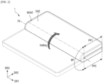
FIG. 1 is a perspective view illustrating a display device according to an example embodiment. -
FIG. 2 is a perspective view illustrating a state in which the display device according to an example embodiment is folded. -
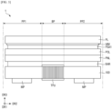
FIG. 3 is a side view schematically illustrating a structure of the display device according to an example embodiment. -
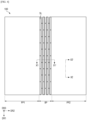
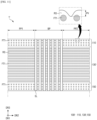
FIG. 4 is a plan view schematically illustrating a panel support of the display device according to an example embodiment. -
FIG. 5 is a cross-sectional view schematically illustrating a cross section taken along line X1-X1' ofFIG. 4 . -
FIG. 6 is a cross-sectional view schematically illustrating a cross section taken along line X2-X2' ofFIG. 4 . -
FIG. 7 is a view for describing a process of manufacturing the panel support of the display device according to an example embodiment. -
FIG. 8 is an image obtained by photographing a cross-section of the panel support of the display device according to an example embodiment, viewed from a first direction. -
FIG. 9 is an image obtained by photographing a cross-section of the panel support of the display device according to an example embodiment, viewed from a second direction. -
FIG. 10 is a graph illustrating a surface step for each position of the panel support of the display device according to an example embodiment. -
FIG. 11 is a cross-sectional view illustrating a structure of a panel support of a display device according to a comparative example. -
FIG. 12 is a cross-sectional view illustrating a structure of a panel support of a display device according to a comparative example. -
FIG. 13 is an image obtained by photographing a cross-section of the panel support of the display device according to an example embodiment, viewed from a second direction. -
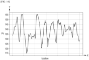
FIG. 14 is a graph illustrating a surface step for each position of a panel support of a display device according to an example embodiment. -
FIG. 15 is a cross-sectional view illustrating a structure of a panel support of a display device according to another example embodiment. -
FIG. 16 is a cross-sectional view illustrating a structure of the panel support of the display device according to the example embodiment ofFIG. 15 . -
FIG. 17 is a graph illustrating a surface step for each position of the panel support of the display device according to the example embodiment ofFIG. 15 . - The advantages and features of the present invention, and the methods for achieving them, will become clear with reference to the embodiments described in detail below with the accompanying drawings. However, the present invention is not limited to the embodiments disclosed below, but may be implemented in various different forms, and these embodiments are provided only to make the disclosure of the present invention complete and to fully inform those skilled in the art of the invention of the scope of the invention, and the present invention is defined only by the scope of the claims.
- When elements or layers are referred to as "on" another element or layer, this includes all cases where another layer or another element is interposed directly on or in the middle of the other element. The same reference numerals refer to the same components throughout the specification. The shapes, sizes, ratios, angles, numbers, etc. disclosed in the drawings for explaining the embodiments are examples, and therefore the present invention is not limited to the matters illustrated.
- Although the terms "first", "second", etc. are used to describe various components, these components are of course not limited by these terms. These terms are only used to distinguish one component from another. Therefore, it goes without saying that the first component mentioned below may also be the second component within the technical concept of the present invention.
- Each of the features of the various embodiments of the present invention may be partially or wholly combined or combined with each other, and various technical connections and operations are possible, and each embodiment may be implemented independently of each other or may be implemented together in a related relationship.
- Specific embodiments will be described below with reference to the attached drawings.
-
FIG. 1 is a perspective view illustrating a display device according to an example embodiment.FIG. 2 is a perspective view illustrating a state in which the display device according to an example embodiment is folded. -
FIG. 1 illustrates a first state of thedisplay device 1 that is unfolded without being bent with respect to a folding axis FX, andFIG. 2 illustrates a second state of thedisplay device 1 bent with respect to the folding axis FX. - Referring to
FIGS. 1 to 2 , thedisplay device 1 according to an example embodiment is a device that displays a moving image or a still image, and may be used as a display screen of various products such as televisions, laptops, monitors, billboards, and Internet of Things, as well as portable electronic devices such as mobile phones, smart phones, tablet PCs, smart watches, watch phones, mobile communication terminals, electronic organizers, e-books, PMPs, navigation, and UMPC. - In
FIG. 1 , a first direction DR1, a second direction DR2, and a third direction DR3 are defined. The first direction DR1 and the second direction DR2 may be perpendicular to each other, the first direction DR1 and the third direction DR3 may be perpendicular to each other, and the second direction DR2 and the third direction DR3 may be perpendicular to each other. It may be understood that the first direction DR1 means a vertical direction in the drawings, the second direction DR2 means a horizontal direction in the drawings, and the third direction DR3 means upper and lower directions in the drawings, that is, a thickness direction. - In the following specification, unless otherwise specified, the term "direction" may refer to both directions toward both sides extending along the direction. In addition, when both "directions" extending to both sides need to be distinguished from each other, one side will be referred to as "one side in the direction" and the other side will be referred to as "the other side in the direction". In
FIG. 1 , a direction in which an arrow indicating a direction is directed is referred to as one side, and an opposite direction thereof is referred to as the other side. However, it should be understood that the directions mentioned in the example embodiments refer to relative directions, and the example embodiments are not limited to the mentioned directions. - In addition, in referring to the surfaces of each member constituting the
display device 1 without being bent with respect to the folding axis FX, one surface facing one side in a direction in which the image is displayed, that is, the third direction DR3 is referred to as a top surface, and an opposite surface of the one surface is referred to as a bottom surface. However, the present disclosure is not limited thereto, and the one surface and the other surface of the member may be referred to as a front surface and a bottom surface, respectively, or may also be referred to as a first surface or a second surface. In addition, in describing relative positions of the members of thedisplay device 1, one side in the third direction DR3 may be referred to as an upper side and the other side in the third direction DR3 may be referred to as a lower side. - A planar shape of the
display device 1 may have a rectangular shape in which a vertical side is longer than a horizontal side as illustrated inFIG. 1 , and each of the corners of thedisplay device 1 may have a right-angled planar shape or a rounded planar shape, but is not limited thereto. For example, the planar shape of thedisplay device 1 may have a rectangular shape in which the vertical side is shorter than the horizontal side.FIG. 1 illustrates a rectangular shape in which the vertical side is longer than the horizontal side. - The
display device 1 includes a first planarization portion PP1, a bending portion BP, and a second planarization portion PP2. The first planarization portion PP1, the bending portion BP and the second planarization portion PP2 defined in thedisplay device 1 may also be applied to each component constituting thedisplay device 1 as illustrated inFIG. 3 . - The first planarization portion PP1 and the second planarization portion PP2 may be portions that are not bent. The first planarization portion PP1 may be disposed on the other side of the
display device 1 in the second direction DR2 as a portion of thedisplay device 1. The second planarization portion PP2 may be disposed on one side of thedisplay device 1 in the second direction DR2 as a portion of the display device 2. - The bending portion BP may be disposed between the first planarization portion PP1 and the second planarization portion PP2. That is, the second planarization portion PP2 may be disposed on one side of the bending portion BP in the second direction DR2, and the first planarization portion PP1 may be disposed on the other side of the bending portion BP in the second direction DR2. A first bending line BL1 may be a boundary between the bending portion BP and the first planarization portion PP1, and the second bending line BL2 may be a boundary between the bending portion BP and the second planarization portion PP2.
- The bending portion BP may be a bendable area. For example, the bending portion BP may be bent with respect to the folding axis FX disposed on the bending portion BP and extending in the first direction DR1. When the bending portion BP is not bent, the
display device 1 may maintain an unfolded state (hereinafter, referred to as a 'first state') as illustrated inFIG. 1 , and when the bending portion BP is bent, thedisplay device 1 may maintain a folded state (hereinafter, referred to as a 'second state') as illustrated inFIG. 2 . - The
display device 1 includes a display area and a non-display area. - The display area may be an area in which pixels are disposed to display a screen. The display area may include a first display area DA1 and a second display area DA2. The non-display area may be an area that does not display a screen. The non-display area may include a first non-display area NDA1 and a second non-display area NDA2.
- In the first state of the
display device 1, one side surface of thedisplay device 1 in the third direction DR3 may be a front surface on which the first display area DA1 and the first non-display area NDA1 are disposed, and the other surface of thedisplay device 1 in the third direction DR3 may be a bottom surface on which the second display area DA2 and the second non-display area NDA2 are disposed. - The first display area DA1 may be disposed on one surface of the
display device 1 in the third direction DR3 in the first state of thedisplay device 1. A planar shape of the first display area DA1 may follow a planar shape of thedisplay device 1 in the first state. For example, when the planar shape of thedisplay device 1 in the first state is a rectangle, the planar shape of the first display area DA1 may also be a rectangle. - In some example embodiments, the first display area DA1 may be surrounded by the first non-display area NDA1, but is not limited thereto. For example, the first display area DA1 may be partially surrounded by the first non-display area NDA1.
FIG. 1 illustrates that the first non-display area NDA1 surrounds the first display area DA1. - The second display area DA2 may be disposed on the other surface of the
display device 1 in the third direction DR3 in the first state of thedisplay device 1, and may overlap only the first planarization portion PP1, but is not limited thereto. The second display area DA2 may display a screen to the user when thedisplay device 1 is in the second state. - The second display area DA2 may follow a planar shape of the first planarization portion PP1 visually recognized by the user in the
display device 1 in the second state as illustrated inFIG. 2 . For example, when the planar shape of the first planarization portion PP1 visually recognized by the user in thedisplay device 1 in the second state is a rectangle, a planar shape of the second display area DA2 may also be a rectangle. - In some example embodiments, the second display area DA2 may be surrounded by the second non-display area NDA2, but is not limited thereto. For example, the second display area DA2 may be partially surrounded by the second non-display area NDA2.
- As illustrated in
FIG. 2 , thedisplay device 1 may be folded in an in-folding manner in which a portion of the first display area DA1 disposed on the first planarization portion PP1 and a portion of the first display area DA1 disposed on the second planarization portion PP2 are folded to face each other in the second state thereof, but is not limited thereto. For example, thedisplay device 1 may be folded in an out-folding manner so that the bottom surfaces thereof face each other.FIG. 2 illustrates that thedisplay device 1 is folded in an in-folding manner. - Hereinafter, a structure of the
display device 1 will be described. -
FIG. 3 is a side view schematically illustrating a structure of the display device according to an example embodiment. - Referring to
FIG. 3 , thedisplay device 1 according to an example embodiment may include an upper protective member PL, a window member WM, a first adhesive member PSA1, a polarizing member POL, a display panel PNL, a barrier member BAR, apanel support 100, a lower visibility preventing member TPU, and a metal support MP. - The upper protective member PL may serve to perform at least one of scattering prevention, shock absorption, engraving prevention, fingerprint prevention, and glare prevention of the window member WM, which will be described later. The upper protective member PL may be disposed on one surface (hereinafter, referred to as a 'front surface') of the window member WM in the third direction DR3. The upper protective member PL may be attached to a front surface of the window member through an adhesive member such as a pressure-sensitive adhesive.
- A light blocking pattern (not illustrated) may be formed on the other surface (hereinafter, referred to as a 'bottom surface') of the upper protective member PL in the third direction DR3. The light blocking pattern may be disposed at an edge of the upper protective member PL or adjacent to the edge. The light blocking pattern may include a light blocking material capable of blocking light. For example, the light blocking pattern may be an inorganic black pigment such as carbon black, an organic black pigment, or an opaque metal material.
- The window member WM may serve to protect the display panel PNL, which will be described later, from the outside. The window member WM may be disposed on one side surface (hereinafter, referred to as a 'front surface') of the display panel PNL in the third direction DR3. The window member WM may be made of a transparent material, for example, glass or plastic.
- The window member WM may be an ultra-thin glass having a thickness of approximately 0.1 mm or less or a transparent polyimide film. The window member WM may be attached to a front surface of the polarizing member POL by the first adhesive member PSA1. The first adhesive member PSA1 may be a transparent adhesive film or a transparent adhesive resin.
- The polarizing member POL may prevent external light incident on the display panel PNL from being reflected. The polarizing member POL may be attached to the window member WM through the first adhesive member PSA1 as a medium. A display panel PNL may be disposed on a bottom surface of the polarizing member POL.
- The display panel PNL is a panel that displays a screen, and any type of display panel such as an organic light emitting display panel including an organic light emitting layer, a micro light emitting diode (LED) display panel using a micro light emitting diode, a quantum dot light emitting display panel using a quantum dot light emitting diode including a quantum dot light emitting layer, and an inorganic light emitting display panel using an inorganic light emitting element including an inorganic semiconductor may be applied as the display panel PNL according to the present example embodiment. Referring to
FIG. 1 , the display panel PNL may display a screen on one side thereof in the third direction DR3. - The barrier member BAR may be disposed on the other side surface (hereinafter, referred to as a 'bottom surface') of the display panel PNL in the third direction DR3. A portion overlapping the bending portion BP among the other side surfaces of the barrier member BAR in the third direction DR3 may be spaced apart from a grid pattern disposed on the bending portion BP of the
panel support 100 to be described later in the third direction DR3. - The barrier member BAR may include at least one of a light blocking layer for absorbing light incident from the outside, a buffer layer for absorbing a shock from the outside, and a heat dissipation layer for efficiently dissipating heat of the display panel PNL.
- The light blocking layer blocks transmission of light and prevents components disposed on a lower side of the light blocking layer from being visually viewed from the front surface of the display panel PNL. The light blocking layer may include a light absorbing material such as a black pigment or a black dye.
- The buffer layer absorbs the external shock to prevent the display panel PNL from being damaged. The buffer layer may be formed as a single layer or a plurality of layers. For example, the buffer layer may be formed of a polymer resin such as polyurethane, polycarbonate, polypropylene, or polyethylene or may include a material having elasticity, such as a sponge formed by foaming rubber, a urethane-based material, or an acrylic-based material.
- The heat dissipation layer may include a first heat dissipation layer including graphite or carbon nano-tube, and a second heat dissipation layer formed of a thin metal film such as copper, nickel, ferrite, or silver that may shield electromagnetic waves and has excellent thermal conductivity.
- The
panel support 100 may serve to support the bottom surface of the display panel PNL. Thepanel support 100 may be disposed on the other surface (hereinafter, referred to as a 'bottom surface') of the barrier member BAR in the third direction DR3. Thepanel support 100 may be a rigid member whose shape or volume is not easily changed by external pressure. A grid pattern for easily bending thepanel support 100 may be formed on the bending portion BP of thepanel support 100. - In some example embodiments, the
panel support 100 may be carbon fiber reinforced plastic (CFRP) including carbon fibers, but is not limited thereto. For example, thepanel support 100 may also be glass fiber reinforced plastic (GFRP) including glass fibers, or aramid fiber reinforced plastic (AFRP). Hereinafter, it will be mainly described that thepanel support 100 is carbon fiber reinforced plastic. The structure of thepanel support 100 will be described later in detail with reference toFIGS. 4 to 6 . - The lower visibility preventing member TPU may be disposed on a bottom surface of the grid pattern formed on the bending portion BP of the
panel support 100. The lower visibility preventing member TPU may prevent the grid pattern of thepanel support 100 from being visually recognized to the outside. The lower visibility preventing member TPU may include a flexible material to reduce folding stress of thedisplay device 1. - The metal support MP may be disposed on a bottom surface of each of the first planarization portion PP1 and the second planarization portion PP2 of the
panel support 100. The metal support MP may serve to support the bottom surface of each of the first planarization portion PP1 and the second planarization portion PP2 of thepanel support 100 and absorb heat generated from the display panel PNL. In some example embodiments, the metal support MP may include copper (Cu), but is not limited thereto. The metal support MP may not be disposed on the bending portion BP to reduce the folding stress of thedisplay device 1. - Hereinafter, a structure of the
panel support 100 of thedisplay device 1 according to an example embodiment will be described with reference toFIGS. 4 to 10 . -
FIG. 4 is a plan view schematically illustrating a panel support of the display device according to an example embodiment. - Referring to
FIG. 4 , thepanel support 100 of thedisplay device 1 according to an example embodiment includes a first planarization portion PP1, a bending portion BP, and a second planarization portion PP2. - The first planarization portion PP1 and the second planarization portion PP2 of the
panel support 100 may be portions that are not bent. The first planarization portion PP1 may be disposed on the other side of thepanel support 100 in the second direction DR2 as a portion of thepanel support 100. The second planarization portion PP2 may be disposed on one side of thepanel support 100 in the second direction DR2 as a portion of thepanel support 100. - The bending portion BP of the
panel support 100 may be disposed between the first planarization portion PP1 and the second planarization portion PP2. That is, the second planarization portion PP2 may be disposed on one side of the bending portion BP in the second direction DR2, and the first planarization portion PP1 may be disposed on the other side of the bending portion BP in the second direction DR2. - The bending portion BP of the
panel support 100 may be a bendable area. A grid pattern including a plurality of slits SL penetrating through thepanel support 100 in the third direction DR3 may be formed on the bending portion BP. The plurality of slits SL are a plurality of columns arranged in the first direction DR1, and may have a shape in which each column is arranged in the second direction DR2. Accordingly, the bending portion BP of thepanel support 100 may be easily bent. -
FIG. 5 is a cross-sectional view schematically illustrating a cross section taken along line X1-X1' ofFIG. 4 .FIG. 6 is a cross-sectional view schematically illustrating a cross section taken along line X2-X2' ofFIG. 4 . - Referring to
FIGS. 5 and6 together withFIG. 4 , thepanel support 100 may be fiber reinforced plastic including fiber yarns and a base resin RS. The fiber yarns may be dispersed in the base resin RS. The fiber yarn may include graphene as a carbon fiber containing carbon, and the base resin RS may be an epoxy-based resin, a polyester-based resin, a polyamide-based resin, a polycarbonate-based resin, a polypropylene-based resin, a polybutylene-based resin, a polyacrylate-based resin, or a vinyl ester-based resin. - The
panel support 100 may include thefirst layer 110, thesecond layer 130, and thethird layer 150 sequentially arranged in the other side in the third direction DR3. For example, thefirst layer 110 of thepanel support 100 may be adjacent to the barrier member BAR (seeFIG. 3 ) disposed on an upper side of thepanel support 100, and thethird layer 150 thereof may be adjacent to the lower visibility preventing member TPU (seeFIG. 3 ) and the metal support MP (seeFIG. 3 ) disposed on a lower side of thepanel support 100. - The base resin RS may be integrally disposed in all of the
first layer 110, thesecond layer 130, and thethird layer 150 of thepanel support 100. In the claims, a portion of the base resin RS disposed in thefirst layer 110 may be referred to as a first base resin, a portion of the base resin RS disposed in thesecond layer 130 may be referred to as a second base resin, and a portion of the base resin RS disposed in thethird layer 150 may be referred to as a third base resin. - The fiber yarns may include first fiber yarns FT1 and second fiber yarns FT2 having different diameters, different elastic moduli, or different carbon contents. The first fiber yarns FT1 may be disposed in the
first layer 110 and thethird layer 150 of thepanel support 100, and the second fiber yarns FT2 may be disposed in thesecond layer 130 of thepanel support 100. In other words, the same type of fiber yarn as the first fiber yarns FT1 may be disposed in thefirst layer 110 and thethird layer 150, and the different type of fiber yarns (for example, the second fiber yarns FT2) from the fiber yarn disposed in thefirst layer 110 and thethird layer 150 as the second fiber yarn FT2 may be disposed in thesecond layer 130. - For example, the
first layer 110 may be a prepreg including the first fiber yarns FT1 extending substantially in parallel in the first direction DR1 and a portion of the base resin RS surrounding the first fiber yarns FT1. Thesecond layer 130 may be a prepreg including the second fiber yarns FT2 extending substantially in parallel in the second direction DR2 and a portion of the base resin RS surrounding the second fiber yarns FT2. For example, the first fiber yarns FT1 and the second fiber yarns FT2 are the different type of fiber yarns with each other. Thethird layer 150 may be a prepreg including the first fiber yarns FT1 extending substantially in parallel in the first direction DR1 and a portion of the base resin RS surrounding the first fiber yarns FT1. - In the present specification, the meaning of 'extending substantially in parallel in the first direction DR1' includes a case that extends that is completely parallel to the first direction DR1 or while forming an angle of intersection of approximately 15° or less by slightly intersecting the second direction DR2, and the meaning of 'extending substantially in parallel in the second direction DR2' includes a case that extends that is completely parallel to the second direction DR2 or while forming an angle of intersection of approximately 15° or less by slightly intersecting the first direction DR1.
- The extending direction of the first fiber yarns FT1 disposed in the
first layer 110 and thethird layer 150 extends substantially in parallel in the first direction DR1, and the first direction DR1 is a direction parallel to the folding axis FX illustrated inFIGS. 1 and2 . Therefore, thefirst layer 110 and thethird layer 150 may be easily folded when thedisplay device 1 is switched from the first state to the second state. However, when thepanel support 100 includes only the first fiber yarns FT1, thepanel support 100 may be curved or bent in the first direction DR1. That is, when thepanel support 100 includes only the first fiber yarns FT1, flatness and rigidity of thepanel support 100 may be low. - Accordingly, as the
panel support 100 further includes thesecond layer 130 having the second fiber yarns FT2 extending substantially in the second direction DR2, it is possible to prevent thepanel support 100 from being curved or bent in the first direction DR1, and to increase the rigidity of thepanel support 100. - However, in consideration of the rigidity required for the
panel support 100, the content of the second fiber yarns FT2 of thepanel support 100 may be greater than the content of the first fiber yarns FT1. For example, a width of thesecond layer 130 of thepanel support 100 in the third direction DR3 may be greater than a width of thefirst layer 110 in the third direction DR3 and a width of thethird layer 150 in the third direction DR3. The width of thefirst layer 110 in the third direction DR3 and the width of thethird layer 150 in the third direction DR3 may be the same as each other. In some example embodiments, a thickness of thefirst layer 110 and a thickness of thethird layer 150 may be approximately 20 µm, and a thickness of thesecond layer 130 may be approximately 100 µm, but the present disclosure is not limited thereto. - Meanwhile, as the fiber yarns extending in one direction are disposed in each layer as described above, it is possible to prevent the thickness of each layer itself from increasing. For example, when both the first fiber yarns FT1 and the second fiber yarns FT2 are disposed in any one layer of the
panel support 100, portions at which the first fiber yarns T1 and the second fiber yarns FT2 intersect may occur, thereby increasing the thickness of the layer itself. Therefore, by disposing the fiber yarns extending only in one direction in each layer, the rigidity required for thepanel support 100 may be secured while minimizing the thickness of the layer itself. - The first fiber yarn FT1 and the second fiber yarn FT2 may be made of carbon fiber and may have a cylindrical shape having a circular cross-section. A diameter d2 of the first fiber yarn FT1 may be greater than a diameter d1 of the second fiber yarn FT2. For example, the diameter d2 of the first fiber yarn FT1 may have a range of approximately 6.5 µm or more and approximately 7.5 µm or less, and the diameter d1 of the second fiber yarn FT2 may have a range of approximately 4.5 µm or more and approximately 5.5 µm or less. Accordingly, the number per unit volume of the first fiber yarns FT1 disposed in the
first layer 110 and thethird layer 150 may be smaller than the number per unit volume of the second fiber yarns FT2 disposed in thesecond layer 130. For example, comparingFIGS. 5 and6 , the number of fiber yarns disposed on the same area may be greater in thesecond layer 130 than in thefirst layer 110 or thethird layer 150. In other words, a gap G1 at which the second fiber yarns FT2 are spaced apart from each other in thesecond layer 130 may be smaller than a gap G2 at which the first fiber yarns FT1 are spaced apart from each other in thefirst layer 110 or thethird layer 150. - On the other hand, as the
first layer 110 and thethird layer 150 include the same type of fiber yarn, each layer of thepanel support 100 may be manufactured without misalignment in a process of manufacturing thepanel support 100 to be described later. - Since the
second layer 130 is stronger than thefirst layer 110 and thethird layer 150 by the configuration as described above, it is possible to reduce visual recognition of the first fiber yarns FT1 disposed in thefirst layer 110 and thethird layer 150 to the outside. - For example, as the base resin RS of the
first layer 110 and thethird layer 150 is thermally contracted in a process of stacking thefirst layer 110, thesecond layer 130, and thethird layer 150 as described below, the surfaces of thefirst layer 110 and thethird layer 150 have a bent shape, and a surface step PV as illustrated inFIG. 6 may be formed. The surface step PV may refer to a gap between a downwardly concave point and an upwardly convex point on the bent surface. Since the surface step PV is formed between the first fiber yarns FT1 disposed in thefirst layer 110 or thethird layer 150, the surface step PV may generally have a shape extending in the first direction DR1. A detailed description thereof will be described with reference toFIGS. 7 to 14 . -
FIG. 7 is a view for describing a process of manufacturing the panel support of the display device according to an example embodiment.FIG. 8 is an image obtained by photographing a cross-section of the panel support of the display device according to an example embodiment, viewed from a first direction.FIG. 9 is an image obtained by photographing a cross-section of the panel support of the display device according to an example embodiment, viewed from a second direction.FIG. 10 is a graph illustrating a surface step for each position of the panel support of the display device according to an example embodiment. - Referring to
FIG. 7 , thefirst layer 110, thesecond layer 130, and thethird layer 150 of thepanel support 100 may be stacked by hot press or autoclave. In this case, the base resin RS disposed in thefirst layer 110, thesecond layer 130, and thethird layer 150 may be melted in the process of stacking thefirst layer 110, thesecond layer 130, and thethird layer 150 and may permeate into a spaced space between the filer yarns of each layer. - For example, as illustrated in
FIGS. 8 and9 , the base resin RS included in thefirst layer 110 and thethird layer 150 is melted in the stacking process and permeates into the spaced space between the second fiber yarns FT2 disposed in thesecond layer 130, so that the surfaces of thefirst layer 110 and thethird layer 150 may have a bent shape. - Accordingly, since the amount of the base resin RS of the
first layer 110 and thethird layer 150 permeating into the spaced space between the second fiber yarns FT2 disposed in thesecond layer 130 in the process of stacking each layer of thepanel support 100 may be reduced by increasing the number per unit volume of the second fiber yarns FT2 disposed in thesecond layer 130 to narrow the spaced space between the second fiber yarns FT2, the degree of curvature of the surfaces of thefirst layer 110 and thethird layer 150 may be reduced. - Referring to
FIG. 10 , a surface step PV for each position of thepanel support 100 as viewed in the second direction DR2 is illustrated. A Y axis of the graph illustrated inFIG. 10 represents the relative degree (dimensionless) of the surface step PV, and an X axis represents a position in the second direction DR2. The inventors of the present specification measured the surface step PV for each position of thepanel support 100 in which the first fiber yarn FT1 is T700 manufactured by Toray company and the second fiber yarn FT2 is T800 manufactured by Toray company as illustrated in the graph ofFIG. 10 through repeated experiments. - T700 manufactured by Toray Company may have a diameter in the range of approximately 6.5 µm or more to approximately 7.5 µm or less, may have a modulus of approximately 240 GPa, and may have a carbon content of approximately 93% or less. T800 manufactured by Toray company may have a diameter in the range of approximately 4.5 µm or more to approximately 5.5 µm or less, may have a modulus of approximately 294 GPa, and may have a carbon content of approximately 96% or less. In this case, the surface step PV of the
panel support 100 of thedisplay device 1 according to an example embodiment may have a relative degree of approximately 148.5 at the maximum to 115 at the minimum. The modulus refers to a modulus of elasticity (Young's modulus) for tensile in the case of fibers. -
FIG. 11 is a cross-sectional view illustrating a structure of a panel support of a display device according to a comparative example.FIG. 12 is a cross-sectional view illustrating a structure of a panel support of a display device according to a comparative example.FIG. 13 is an image obtained by photographing a cross-section of the panel support of the display device according to an example embodiment, viewed from a second direction.FIG. 14 is a graph illustrating a surface step for each position of a panel support of a display device according to an example embodiment. - Referring to
FIGS. 11 to 14 , a panel support 100' of a display device 1' according to a comparative example is different from thepanel support 100 of thedisplay device 1 according to an example embodiment in that a second layer 130' of the panel support 100' includes the first fiber yarns FT1 as the fiber yarns, and other configurations are substantially the same or similar. In other words, thefirst layer 110, the second layer 130', and thethird layer 150 may have the same type of fiber yarn, and the number of fiber yarns per unit volume of thefirst layer 110, the second layer 130', and thethird layer 150 may also be the same. - In this case, a step PV formed on the surface of the
first layer 110 of the display device 1' according to the comparative example illustrated inFIG. 12 may be greater than the surface step PV formed on the surface of thefirst layer 110 of thedisplay device 1 according to the example embodiment illustrated inFIG. 6 . This is because, as illustrated inFIG. 11 to 13 , a diameter of the first fiber yarn FT1 as the fiber yarn disposed in the second layer 130' is greater than the diameter of the second fiber yarn FT2 disposed in thesecond layer 130 of thepanel support 100 according to an example embodiment, and accordingly, the number of fiber yarns disposed per unit volume of the second layer 130' in the comparative example is reduced to increase a spaced distance between the fiber yarns of the second layer 130', so that an amount of the base resin RS of thefirst layer 110 and thethird layer 150 permeating into the second layer 130' increases in the stacking process as described above inFIG. 7 . - Referring to
FIGS. 12 and14 , a surface step PV for each position of the panel support 100' as viewed in the second direction DR2 is illustrated. A Y axis of the graph illustrated inFIG. 14 represents the relative degree (dimensionless) of the surface step PV, and an X axis represents a position in the second direction DR2. The inventors of the present specification measured the surface step PV for each position of thepanel support 100 in which the first fiber yarn FT1 is T700 manufactured by Toray Company as illustrated in the graph ofFIG. 14 through repeated experiments. - In this case, the surface step PV of the panel support 100' of the display device 1' according to the comparative example may have a relative degree of approximately 155.4 at the maximum to 115 at the minimum.
- That is, referring to
FIGS. 6 ,10 ,12 and14 , since the surface step PV of thepanel support 100 of thedisplay device 1 according to an example embodiment has the relative degree of approximately 148.5 at the maximum to 115 at the minimum, and the surface step PV of the panel support 100' of the display device 1' according to the comparative example has the relative degree of approximately 155.4 at the maximum to 115 at the minimum, it may be seen that the surface step PV of thepanel support 100 of thedisplay device 1 according to an example embodiment is reduced compared to the surface step PV of the panel support 100' of the display device 1' according to the comparative example. - Hereinafter, other example embodiments of the
display device 1 will be described. In the following example embodiments, the same components as those of the above-described example embodiment will be denoted by the same reference numerals, and an overlapping description thereof will be omitted or simplified and differences will be mainly described. -
FIG. 15 is a cross-sectional view illustrating a structure of a panel support of a display device according to another example embodiment.FIG. 16 is a cross-sectional view illustrating a structure of the panel support of the display device according to the example embodiment ofFIG. 15 .FIG. 17 is a graph illustrating a surface step for each position of the panel support of the display device according to the example embodiment ofFIG. 15 . - Referring to
FIGS. 15 and16 , a panel support 100_1 of a display device 1_1 according to the present example embodiment is different from thepanel support 100 of thedisplay device 1 according to an example embodiment in that a modulus of the fiber yarn disposed in a second layer 130_1 of the panel support 100_1 is greater than that of the fiber yarn disposed in thesecond layer 130 of thepanel support 100, and other configurations are substantially same or similar. - For example, the modulus of the third fiber yarn FT3 disposed in the second layer 130_1 of the display device 1_1 according to the present example embodiment may be greater than the modulus of the second fiber yarn FT2 disposed in the
second layer 130 of thedisplay device 1 according to an example embodiment. The diameter d1 of the third fiber yarn FT3 according to the embodiment ofFIGS. 15 and16 may be in the range of approximately 4.5 µm or more and approximately 5.5 µm or less, and may be substantially the same as the diameter d1 of the second fiber yarn FT2. The diameter d1 of the third fiber yarn FT3 according to the embodiment ofFIGS. 15 and16 is substantially same as the diameter d1 of the second fiber yarn FT2 according to the embodiment ofFIGS. 5 and6 . A gap G1 at which the third fiber yarns FT3 are spaced apart from each other in the second layer 130_1 may be smaller than the gap G2 (seeFIG. 6 ) at which the first fiber yarns FT1 are spaced apart from each other in thefirst layer 110 or thethird layer 150. - The modulus of the third fiber yarn FT3 may be greater than the modulus of the first fiber yarn FT1. In general, when the fiber yarn includes carbon fibers, there may be a correlation that the modulus increases as the carbon content increases. Accordingly, the carbon content of the third fiber yarn FT3 may be greater than the carbon content of the first fiber yarn FT1. In some example embodiments, the modulus of the third fiber yarn FT3 may be approximately 377 GPa or more, and the modulus of the first fiber yarn FT1 may be approximately 240 GPa or less, and the carbon content of the third fiber yarn FT3 may be approximately 99% or more, and the carbon content of the first fiber yarn FT1 may be approximately 93% or less, but the present disclosure is not limited thereto.
- Since the second layer 130_1 of the panel support 100_1 according to the present example embodiment includes the fiber yarn having a higher modulus than that of the
first layer 110 and thethird layer 150 by the configuration as described above, the second layer 130_1 may have stronger rigidity than that of the first andthird layers first layer 110 and thethird layer 150 to the outside. - For example, as described above with reference to
FIG. 7 , as the base resin RS of thefirst layer 110 and thethird layer 150 is thermally contracted in the process of stacking thefirst layer 110, thesecond layer 130, and thethird layer 150, the surfaces of thefirst layer 110 and thethird layer 150 have the bent shape. In this case, when the second layer 130_1 has the stronger rigidity than that of thefirst layer 110 and thethird layer 150, the surface step PV generated by the thermal contraction may be reduced by reducing the degree of thermal contraction of the base resin RS of thefirst layer 110 and thethird layer 150. - For example, the surface step PV formed in the panel support 100_1 of the display device 1_1 according to the present example embodiment may be smaller than the surface step PV (see
FIG. 6 ) formed in thepanel support 100 of thedisplay device 1 according to an example embodiment. This is because the third fiber yarn FT3 of the display device 1_1 according to the present example embodiment has the greater modulus than that of the second fiber yarn FT2 of thedisplay device 1 according to an example embodiment. - Referring to
FIG. 17 , a surface step PV for each position of the panel support 100_1 as viewed in the second direction DR2 is illustrated. A Y axis of the graph illustrated inFIG. 17 represents the relative degree (dimensionless) of the surface step PV, and an X axis represents a position in the second direction DR2. The inventors of the present specification measured the surface step PV for each position of the panel support 100_1 in which the first fiber yarn FT1 is T700 manufactured by Toray Company and the third fiber yarn FT3 is M40 manufactured by Toray Company as illustrated in the graph ofFIG. 17 through repeated experiments. - T700 manufactured by Toray Company may have a diameter in the range of 6.5 µm or more to 7.5 µm or less, may have a modulus of approximately 240 GPa, and may have a carbon content of 93% or less. M40 manufactured by Toray Company may have a diameter in the range of 4.5 µm or more and 5.5 µm or less, may have a modulus of approximately 377 GPa, and may have a carbon content of 99% or less. In this case, the surface step PV of the panel support 100_1 of the display device 1_1 according to the present example embodiment may have a relative degree of approximately 140.1 at the maximum to 115 at the minimum.
- That is, referring to
FIGS. 10 to 17 , since the surface step PV of thepanel support 100 of thedisplay device 1 according to an example embodiment has the relative degree of approximately 148.5 at the maximum to 115 at the minimum, and the surface step PV of the panel support 100_1 of the display device 1_1 according to the present example embodiment has the relative degree of approximately 140.1 at the maximum to 115 at the minimum, it may be seen that the surface step PV of the panel support 100_1 of the display device 1_1 according to the present example embodiment is reduced compared to the surface step PV of thepanel support 100 of thedisplay device 1 according to an example embodiment. - Although the embodiments of the present invention have been described with reference to the attached drawings, those skilled in the art will understand that the present invention can be implemented in other specific forms without changing the technical idea or essential features of the present invention. Therefore, it should be understood that the embodiments described above are examples in all respects and not restrictive.
Claims (23)
- A display device comprising:a display panel having a folding axis extending in a first direction; anda panel support disposed on one surface of the display panel,wherein the panel support includes:a first layer including a first base resin and first fiber yarns extending in the first direction and dispersed in the first base resin;a second layer disposed on the first layer, the second layer including a second base resin and second fiber yarns extending in a second direction intersecting the first direction and dispersed in the second base resin; anda third layer disposed on the second layer, the third layer including a third base resin and third fiber yarns extending in the first direction and dispersed in the third base resin, andwherein the number of second fiber yarns per unit volume of the second layer is greater than the number of first fiber yarns per unit volume of the first layer and the number of third fiber yarns per unit volume of the third layer.
- The display device of claim 1, wherein a diameter of the second fiber yarn is smaller than a diameter of the first fiber yarn and a diameter of the third fiber yarn.
- The display device of claim 2, wherein the diameter of the first fiber yarn and the diameter of the third fiber yarn are the same.
- The display device of claim 3, wherein a spaced distance between the second fiber yarns in the second layer is smaller than a spaced distance between the first fiber yarns in the first layer and a spaced distance between the third fiber yarns in the third layer.
- The display device of claim 4, wherein the diameter of the second fiber yarn is 4.5 µm or more and 5.5 µm or less, and
the diameter of the first fiber yarn and the diameter of the third fiber yarn are 6.5 µm or more and 7.5 µm or less. - The display device of claim 1, wherein a thickness of the second layer is greater than a thickness of the first layer and a thickness of the third layer.
- The display device of claim 6, wherein the second layer is disposed between the first layer and the third layer.
- The display device of claim 7, wherein the thickness of the first layer and the thickness of the third layer are the same as each other.
- The display device of claim 1, wherein the first fiber yarn, the second fiber yarn and the third fiber yarn include carbon, and
a carbon content of the second fiber yarn is greater than a carbon content of the first fiber yarn and a carbon content of the third fiber yarn. - The display device of claim 1, wherein a modulus of the second fiber yarn is greater than a modulus of the first fiber yarn and a modulus of the third fiber yarn.
- A display device comprising:a display panel having a folding axis extending in a first direction; anda panel support disposed on one surface of the display panel,wherein the panel support includes:a first layer including a first base resin and first fiber yarns extending in the first direction and dispersed in the first base resin;a second layer disposed on the first layer, the second layer including a second base resin and second fiber yarns extending in a second direction intersecting the first direction and dispersed in the second base resin; anda third layer disposed on the second layer, the third layer including a third base resin and third fiber yarns extending in the first direction and dispersed in the third base resin, andwherein a modulus of the second fiber yarn is greater than a modulus of the first fiber yarn and a modulus of the third fiber yarn.
- The display device of claim 11, wherein the modulus of the first fiber yarn and the modulus of the third fiber yarn are the same as each other.
- The display device of claim 12, wherein a thickness of the second layer is greater than a thickness of the first layer and a thickness of the third layer.
- The display device of claim 13, wherein the second layer is disposed between the first layer and the third layer.
- The display device of claim 14, wherein the modulus of the second fiber yarn is 290 GPa or more, and
the modulus of the first fiber yarn and the modulus of the third fiber yarn are 240 GPa or less. - The display device comprising:a display panel having a folding axis extending in a first direction; anda panel support disposed on one surface the display panel,wherein the panel support includes:a first layer including a first base resin and first fiber yarns extending in the first direction and dispersed in the first base resin;a second layer disposed on the first layer, the second layer including a second base resin and second fiber yarns extending in a second direction intersecting the first direction and dispersed in the second base resin; anda third layer disposed on the second layer, the third layer including a third base resin and third fiber yarns extending in the first direction and dispersed in the third base resin, and
wherein a carbon content of the second fiber yarn is greater than a carbon content of the first fiber yarn and a carbon content of the third fiber yarn. - The display device of claim 16, wherein the carbon content of the first fiber yarn and the carbon content of the third fiber yarn are the same as each other.
- The display device of claim 17, wherein a thickness of the second layer is greater than a thickness of the first layer and a thickness of the third layer.
- The display device of claim 18, wherein the second layer is disposed between the first layer and the third layer.
- The display device of claim 19, wherein the carbon content of the second fiber yarn is 96% or more, and
the carbon content of the first fiber yarn and the carbon content of the third fiber yarn are 93% or less. - 21. A display device comprising:a display panel having a folding axis extending in a first direction; anda panel support disposed on one surface of the display panel and including a base resin and fiber yarns dispersed in the base resin,wherein the fiber yarns include:first fiber yarns extending in the first direction;second fiber yarns extending in a second direction intersecting the first direction; andthird fiber yarns extending in the first direction,the base resin includes:a first portion in which the first fiber yarns are dispersed;a second portion disposed on the first portion, the second fiber yarns being dispersed in the second portion; anda third portion disposed on the second portion, the third fiber yarns being dispersed in the third portion, andwherein the number of second fiber yarns per unit volume of the second portion is greater than the number of first fiber yarns per unit volume of the first portion and the number of third fiber yarns per unit volume of the third portion.
- The display device of claim 21, wherein a diameter of the second fiber yarn is smaller than a diameter of the first fiber yarn and a diameter of the third fiber yarn.
- The display device of claim 22, wherein a spaced distance between the second fiber yarns in the second portion is smaller than a spaced distance between the first fiber yarns in the first portion and a spaced distance between the third fiber yarns in the third portion.
Applications Claiming Priority (2)
| Application Number | Priority Date | Filing Date | Title |
|---|---|---|---|
| KR1020220110685A KR20240032239A (en) | 2022-09-01 | 2022-09-01 | Display device |
| PCT/KR2023/012331 WO2024049074A1 (en) | 2022-09-01 | 2023-08-21 | Display device |
Publications (1)
| Publication Number | Publication Date |
|---|---|
| EP4583082A1 true EP4583082A1 (en) | 2025-07-09 |
Family
ID=90017118
Family Applications (1)
| Application Number | Title | Priority Date | Filing Date |
|---|---|---|---|
| EP23860752.7A Pending EP4583082A1 (en) | 2022-09-01 | 2023-08-21 | Display device |
Country Status (6)
| Country | Link |
|---|---|
| US (1) | US20240081001A1 (en) |
| EP (1) | EP4583082A1 (en) |
| JP (1) | JP2025529084A (en) |
| KR (1) | KR20240032239A (en) |
| CN (2) | CN221079544U (en) |
| WO (1) | WO2024049074A1 (en) |
Family Cites Families (5)
| Publication number | Priority date | Publication date | Assignee | Title |
|---|---|---|---|---|
| KR102086098B1 (en) * | 2013-07-03 | 2020-03-09 | 삼성디스플레이 주식회사 | Display device |
| KR102051803B1 (en) * | 2013-07-29 | 2020-01-09 | 삼성디스플레이 주식회사 | Foldable display device |
| KR101737155B1 (en) * | 2013-09-26 | 2017-05-17 | 제일모직주식회사 | Window sheet and displaying apparatus comprising the same |
| CN109377889B (en) * | 2018-12-19 | 2020-08-11 | 武汉华星光电半导体显示技术有限公司 | Flexible display device |
| KR20220106258A (en) * | 2021-01-21 | 2022-07-29 | 삼성디스플레이 주식회사 | Electronic device |
-
2022
- 2022-09-01 KR KR1020220110685A patent/KR20240032239A/en active Pending
-
2023
- 2023-05-01 US US18/309,876 patent/US20240081001A1/en active Pending
- 2023-08-21 WO PCT/KR2023/012331 patent/WO2024049074A1/en not_active Ceased
- 2023-08-21 JP JP2025511891A patent/JP2025529084A/en active Pending
- 2023-08-21 EP EP23860752.7A patent/EP4583082A1/en active Pending
- 2023-08-23 CN CN202322273919.5U patent/CN221079544U/en active Active
- 2023-08-23 CN CN202311066914.3A patent/CN117636741A/en active Pending
Also Published As
| Publication number | Publication date |
|---|---|
| WO2024049074A1 (en) | 2024-03-07 |
| JP2025529084A (en) | 2025-09-04 |
| KR20240032239A (en) | 2024-03-12 |
| CN221079544U (en) | 2024-06-04 |
| US20240081001A1 (en) | 2024-03-07 |
| CN117636741A (en) | 2024-03-01 |
Similar Documents
| Publication | Publication Date | Title |
|---|---|---|
| US12019471B2 (en) | Window and display device including same | |
| US11216034B2 (en) | Display device having improved impact resistance and electronic device having the same | |
| EP3671703B1 (en) | Foldable cover plate, foldable display module, and foldable terminal device | |
| US11940846B2 (en) | Display device | |
| US11985774B2 (en) | Display device | |
| KR20190053691A (en) | Display device | |
| CN113888964B (en) | Display Devices | |
| CN113192419B (en) | Display module and display device | |
| US12268081B2 (en) | Display device and method of manufacturing the same | |
| US12507352B2 (en) | Display device | |
| US12267450B2 (en) | Display device | |
| EP3965179B1 (en) | Display device | |
| US20240357918A1 (en) | Display device and method for manufacturing the same | |
| KR20220063834A (en) | Display device | |
| US20230052151A1 (en) | Display device | |
| KR20230063998A (en) | Window and electronic device including the same | |
| CN221079544U (en) | Display device | |
| US12265420B2 (en) | Display device | |
| KR20240056898A (en) | Display device | |
| KR20230116995A (en) | Supporter of display panel and display device including the same | |
| CN221532031U (en) | Display device | |
| US20240206095A1 (en) | Electronic device | |
| KR20250173020A (en) | Display device and method for manufacturing cover window | |
| EP4303694A1 (en) | Support member for display device and display device including the same | |
| CN120659488A (en) | Display device |
Legal Events
| Date | Code | Title | Description |
|---|---|---|---|
| STAA | Information on the status of an ep patent application or granted ep patent |
Free format text: STATUS: THE INTERNATIONAL PUBLICATION HAS BEEN MADE |
|
| PUAI | Public reference made under article 153(3) epc to a published international application that has entered the european phase |
Free format text: ORIGINAL CODE: 0009012 |
|
| STAA | Information on the status of an ep patent application or granted ep patent |
Free format text: STATUS: REQUEST FOR EXAMINATION WAS MADE |
|
| 17P | Request for examination filed |
Effective date: 20250226 |
|
| AK | Designated contracting states |
Kind code of ref document: A1 Designated state(s): AL AT BE BG CH CY CZ DE DK EE ES FI FR GB GR HR HU IE IS IT LI LT LU LV MC ME MK MT NL NO PL PT RO RS SE SI SK SM TR |
|
| REG | Reference to a national code |
Ref country code: DE Ref legal event code: R079 Free format text: PREVIOUS MAIN CLASS: G09F0009300000 Ipc: H10K0050800000 |
|
| DAV | Request for validation of the european patent (deleted) | ||
| DAX | Request for extension of the european patent (deleted) | ||
| RIC1 | Information provided on ipc code assigned before grant |
Ipc: H10K 50/80 20230101AFI20251204BHEP Ipc: H10K 59/00 20230101ALI20251204BHEP Ipc: G09F 9/30 20060101ALI20251204BHEP Ipc: G06F 1/16 20060101ALI20251204BHEP Ipc: B32B 5/26 20060101ALI20251204BHEP Ipc: B32B 5/04 20060101ALI20251204BHEP |
|
| P01 | Opt-out of the competence of the unified patent court (upc) registered |
Free format text: CASE NUMBER: UPC_APP_0007672_4583082/2026 Effective date: 20260226 |