EP4583075A1 - Control system, control method, and control program - Google Patents
Control system, control method, and control program Download PDFInfo
- Publication number
- EP4583075A1 EP4583075A1 EP23859711.6A EP23859711A EP4583075A1 EP 4583075 A1 EP4583075 A1 EP 4583075A1 EP 23859711 A EP23859711 A EP 23859711A EP 4583075 A1 EP4583075 A1 EP 4583075A1
- Authority
- EP
- European Patent Office
- Prior art keywords
- moving body
- area
- blockage
- safety
- intruding
- Prior art date
- Legal status (The legal status is an assumption and is not a legal conclusion. Google has not performed a legal analysis and makes no representation as to the accuracy of the status listed.)
- Pending
Links
Images







Classifications
-
- G—PHYSICS
- G08—SIGNALLING
- G08G—TRAFFIC CONTROL SYSTEMS
- G08G1/00—Traffic control systems for road vehicles
- G08G1/09—Arrangements for giving variable traffic instructions
- G08G1/0962—Arrangements for giving variable traffic instructions having an indicator mounted inside the vehicle, e.g. giving voice messages
- G08G1/0967—Systems involving transmission of highway information, e.g. weather, speed limits
- G08G1/096708—Systems involving transmission of highway information, e.g. weather, speed limits where the received information might be used to generate an automatic action on the vehicle control
- G08G1/096725—Systems involving transmission of highway information, e.g. weather, speed limits where the received information might be used to generate an automatic action on the vehicle control where the received information generates an automatic action on the vehicle control
-
- G—PHYSICS
- G08—SIGNALLING
- G08G—TRAFFIC CONTROL SYSTEMS
- G08G1/00—Traffic control systems for road vehicles
- G08G1/16—Anti-collision systems
- G08G1/166—Anti-collision systems for active traffic, e.g. moving vehicles, pedestrians, bikes
-
- B—PERFORMING OPERATIONS; TRANSPORTING
- B60—VEHICLES IN GENERAL
- B60W—CONJOINT CONTROL OF VEHICLE SUB-UNITS OF DIFFERENT TYPE OR DIFFERENT FUNCTION; CONTROL SYSTEMS SPECIALLY ADAPTED FOR HYBRID VEHICLES; ROAD VEHICLE DRIVE CONTROL SYSTEMS FOR PURPOSES NOT RELATED TO THE CONTROL OF A PARTICULAR SUB-UNIT
- B60W30/00—Purposes of road vehicle drive control systems not related to the control of a particular sub-unit, e.g. of systems using conjoint control of vehicle sub-units
- B60W30/08—Active safety systems predicting or avoiding probable or impending collision or attempting to minimise its consequences
-
- B—PERFORMING OPERATIONS; TRANSPORTING
- B60—VEHICLES IN GENERAL
- B60W—CONJOINT CONTROL OF VEHICLE SUB-UNITS OF DIFFERENT TYPE OR DIFFERENT FUNCTION; CONTROL SYSTEMS SPECIALLY ADAPTED FOR HYBRID VEHICLES; ROAD VEHICLE DRIVE CONTROL SYSTEMS FOR PURPOSES NOT RELATED TO THE CONTROL OF A PARTICULAR SUB-UNIT
- B60W30/00—Purposes of road vehicle drive control systems not related to the control of a particular sub-unit, e.g. of systems using conjoint control of vehicle sub-units
- B60W30/08—Active safety systems predicting or avoiding probable or impending collision or attempting to minimise its consequences
- B60W30/09—Taking automatic action to avoid collision, e.g. braking and steering
-
- B—PERFORMING OPERATIONS; TRANSPORTING
- B60—VEHICLES IN GENERAL
- B60W—CONJOINT CONTROL OF VEHICLE SUB-UNITS OF DIFFERENT TYPE OR DIFFERENT FUNCTION; CONTROL SYSTEMS SPECIALLY ADAPTED FOR HYBRID VEHICLES; ROAD VEHICLE DRIVE CONTROL SYSTEMS FOR PURPOSES NOT RELATED TO THE CONTROL OF A PARTICULAR SUB-UNIT
- B60W30/00—Purposes of road vehicle drive control systems not related to the control of a particular sub-unit, e.g. of systems using conjoint control of vehicle sub-units
- B60W30/08—Active safety systems predicting or avoiding probable or impending collision or attempting to minimise its consequences
- B60W30/095—Predicting travel path or likelihood of collision
- B60W30/0953—Predicting travel path or likelihood of collision the prediction being responsive to vehicle dynamic parameters
-
- B—PERFORMING OPERATIONS; TRANSPORTING
- B60—VEHICLES IN GENERAL
- B60W—CONJOINT CONTROL OF VEHICLE SUB-UNITS OF DIFFERENT TYPE OR DIFFERENT FUNCTION; CONTROL SYSTEMS SPECIALLY ADAPTED FOR HYBRID VEHICLES; ROAD VEHICLE DRIVE CONTROL SYSTEMS FOR PURPOSES NOT RELATED TO THE CONTROL OF A PARTICULAR SUB-UNIT
- B60W30/00—Purposes of road vehicle drive control systems not related to the control of a particular sub-unit, e.g. of systems using conjoint control of vehicle sub-units
- B60W30/08—Active safety systems predicting or avoiding probable or impending collision or attempting to minimise its consequences
- B60W30/095—Predicting travel path or likelihood of collision
- B60W30/0956—Predicting travel path or likelihood of collision the prediction being responsive to traffic or environmental parameters
-
- B—PERFORMING OPERATIONS; TRANSPORTING
- B60—VEHICLES IN GENERAL
- B60W—CONJOINT CONTROL OF VEHICLE SUB-UNITS OF DIFFERENT TYPE OR DIFFERENT FUNCTION; CONTROL SYSTEMS SPECIALLY ADAPTED FOR HYBRID VEHICLES; ROAD VEHICLE DRIVE CONTROL SYSTEMS FOR PURPOSES NOT RELATED TO THE CONTROL OF A PARTICULAR SUB-UNIT
- B60W30/00—Purposes of road vehicle drive control systems not related to the control of a particular sub-unit, e.g. of systems using conjoint control of vehicle sub-units
- B60W30/14—Adaptive cruise control
- B60W30/143—Speed control
-
- B—PERFORMING OPERATIONS; TRANSPORTING
- B60—VEHICLES IN GENERAL
- B60W—CONJOINT CONTROL OF VEHICLE SUB-UNITS OF DIFFERENT TYPE OR DIFFERENT FUNCTION; CONTROL SYSTEMS SPECIALLY ADAPTED FOR HYBRID VEHICLES; ROAD VEHICLE DRIVE CONTROL SYSTEMS FOR PURPOSES NOT RELATED TO THE CONTROL OF A PARTICULAR SUB-UNIT
- B60W50/00—Details of control systems for road vehicle drive control not related to the control of a particular sub-unit, e.g. process diagnostic or vehicle driver interfaces
- B60W50/08—Interaction between the driver and the control system
- B60W50/14—Means for informing the driver, warning the driver or prompting a driver intervention
-
- G—PHYSICS
- G08—SIGNALLING
- G08G—TRAFFIC CONTROL SYSTEMS
- G08G1/00—Traffic control systems for road vehicles
- G08G1/09—Arrangements for giving variable traffic instructions
- G08G1/0962—Arrangements for giving variable traffic instructions having an indicator mounted inside the vehicle, e.g. giving voice messages
- G08G1/0967—Systems involving transmission of highway information, e.g. weather, speed limits
- G08G1/096766—Systems involving transmission of highway information, e.g. weather, speed limits where the system is characterised by the origin of the information transmission
- G08G1/096775—Systems involving transmission of highway information, e.g. weather, speed limits where the system is characterised by the origin of the information transmission where the origin of the information is a central station
-
- G—PHYSICS
- G08—SIGNALLING
- G08G—TRAFFIC CONTROL SYSTEMS
- G08G1/00—Traffic control systems for road vehicles
- G08G1/16—Anti-collision systems
- G08G1/161—Decentralised systems, e.g. inter-vehicle communication
- G08G1/162—Decentralised systems, e.g. inter-vehicle communication event-triggered
-
- G—PHYSICS
- G08—SIGNALLING
- G08G—TRAFFIC CONTROL SYSTEMS
- G08G1/00—Traffic control systems for road vehicles
- G08G1/16—Anti-collision systems
- G08G1/161—Decentralised systems, e.g. inter-vehicle communication
- G08G1/163—Decentralised systems, e.g. inter-vehicle communication involving continuous checking
-
- G—PHYSICS
- G08—SIGNALLING
- G08G—TRAFFIC CONTROL SYSTEMS
- G08G1/00—Traffic control systems for road vehicles
- G08G1/16—Anti-collision systems
- G08G1/164—Centralised systems, e.g. external to vehicles
-
- B—PERFORMING OPERATIONS; TRANSPORTING
- B60—VEHICLES IN GENERAL
- B60W—CONJOINT CONTROL OF VEHICLE SUB-UNITS OF DIFFERENT TYPE OR DIFFERENT FUNCTION; CONTROL SYSTEMS SPECIALLY ADAPTED FOR HYBRID VEHICLES; ROAD VEHICLE DRIVE CONTROL SYSTEMS FOR PURPOSES NOT RELATED TO THE CONTROL OF A PARTICULAR SUB-UNIT
- B60W2554/00—Input parameters relating to objects
- B60W2554/40—Dynamic objects, e.g. animals, windblown objects
- B60W2554/402—Type
- B60W2554/4029—Pedestrians
Definitions
- the present invention relates to a control system, a control method, and a control program.
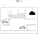
- FIG. 1 is a diagram illustrating a configuration of a control system 0 according to a first embodiment.
- the control system 0 includes an in-vehicle device 1, a control device 2, and a moving body 3.
- the in-vehicle device 1 has a function of traveling of the vehicle, and performs automatic driving by receiving information for assisting vehicle control from the control device 2 as necessary. That is, the in-vehicle device 1 constitutes an automatic driving vehicle that is a vehicle (moving body) capable of automatic driving.
- the control device 2 receives moving body information 201 ( FIG. 2 ) such as a position, a speed, and a travel plan from the in-vehicle device 1 and the moving body 3, performs blockage control on an arbitrary area, and gives an instruction to the in-vehicle device 1 and the moving body 3.
- the moving body 3 is a manned vehicle (non-automatic driving vehicle) or a person (pedestrian) that can exist around the in-vehicle device 1.
- the control device 2 includes a blockage candidate calculation unit 21, a safety instruction generation unit 22, and a safety notification unit 23.
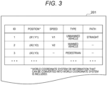
- the moving body information 201 manages a position, a speed, a type, and a path (travel plan) of each moving body (in-vehicle device 1 and moving body 3) existing in the assumed environment of the present embodiment by assigning an ID. This information may be notified to the control device 2 by each moving body (in-vehicle device 1 and moving body 3), or may be detected by using an infrastructure sensor or the like.
- the type of each moving body is classified into at least a moving body capable of controlling an action (for example, an unmanned vehicle) and a moving body incapable of controlling an action (for example, a manned vehicle or a person).
- the blockage area 202 is an area where a specific moving body (in-vehicle device 1) travels until the specific moving body stops by applying braking.
- step S211 the premise is as follows.
- Vehicle coordinate system Vehicle coordinate system (Vehicle coordinate system and world coordinate system can be transformed.)
- step S213 the braking distance D_stop is calculated.
- the blockage area 202 is obtained from a vehicle width, a vehicle length, a trajectory (travel plan), a position, a speed, and an acceleration (deceleration). An example will be described below.
- FIG. 9 is a diagram illustrating another example of the processing flow of calculation of the blockage area 202.
- FIG. 10 is a diagram illustrating a specific example when the blockage area 202 is calculated by the processing flow illustrated in FIG. 9 .
- the blockage candidate calculation unit 21 calculates, as the warning area, an area where the moving body 3 travels outside the blockage area during the braking time on the basis of the position and the travel plan of the moving body 3, and the speed of the moving body 3 or the assumed maximum speed of the moving body 3.
- FIG. 11 is a diagram illustrating a processing flow of the safety instruction generation unit 22.
- step S221 it is determined whether or not the moving body 3 (another moving body) exists in the blockage area 202, in a case where the moving body 3 (another moving body) exists, the process proceeds to step S226, and in a case where the moving body 3 does not exist, the process proceeds to step S222.
- step S222 it is determined whether or not the moving body 3 exists in the warning area 203, and in a case where the moving body 3 exists, the process proceeds to step S223, and in a case where the moving body 3 does not exist, the process ends.
- step S223 it is determined whether or not the moving body 3 is an unmanned vehicle, and in a case where the moving body 3 is an unmanned vehicle, the process proceeds to step S224, and in a case where the moving body 3 is not an unmanned vehicle, the process proceeds to step S226.
- step S224 it is determined whether or not the travel plan is a plan not to intrude into the blockage area 202, and in a case where the travel plan is a plan not to intrude into the blockage area 202, the process is terminated, and in a case where the travel plan is a plan to intrude into the blockage area 202, the process proceeds to step S225.
- step S225 it is determined whether or not the host vehicle is prioritized, and in a case where the host vehicle is prioritized, the process is terminated, and in a case where the host vehicle is not prioritized, the process proceeds to step S226.
- step S226 the safety instruction information 204 ( FIG. 6 ) is generated.
- the safety instruction generation unit 22 determines contents to be instructed to the vehicle.
- the safety instruction generation unit 22 generates the safety action instruction (safety instruction information 204) on the basis of the type (blockage area, warning area) of the area calculated by the blockage candidate calculation unit 21 and the type (unmanned vehicle, manned vehicle, etc.) of the moving body 3 (another moving body) intruding into the area.
- the safety notification unit 23 notifies (the output arbitration unit 12 of) the in-vehicle device 1 of the safety action instruction (safety instruction information 204) generated by the safety instruction generation unit 22.
- the blockage area 202 and the warning area 203 are calculated, and braking is performed in a case of intrusion into the blockage area 202 or the warning area 203, so that it is possible to prevent collision with the moving body 3.
- traveling efficiency can be improved.
- the difference from the first embodiment is that, by permitting the intrusion of the moving body 3 into the warning area 203 by adding the rule information 205, it is possible to improve the traveling efficiency while ensuring the safety when the rule is observed.
- FIG. 12 is a diagram illustrating a processing flow of the safety instruction generation unit 22 in the second embodiment.
- step S227 rule information is acquired.
- step S221 it is determined whether or not the moving body 3 (another moving body) exists in the blockage area 202, in a case where the moving body 3 (another moving body) exists, the process proceeds to step S226, and in a case where the moving body 3 does not exist, the process proceeds to step S222.
- step S222 it is determined whether or not the moving body 3 exists in the warning area 203, in a case where the moving body 3 exists, the process proceeds to step S228, and in a case where the moving body 3 does not exist, the process ends.
- step S2208 with reference to the rule information 205, it is determined whether to permit the intrusion of the moving body 3 existing in the warning area 203, in a case where the intrusion is permitted, the process is terminated, and in a case where the intrusion is not permitted, the process proceeds to step S226.
- step S226 the safety instruction information 204 ( FIG. 6 ) is generated.
- the safety instruction generation unit 22 determines contents to be instructed to the vehicle.
- the safety instruction generation unit 22 generates the safety action instruction (safety instruction information 204) on the basis of the rule in addition to the type (blockage area, warning area) of the area calculated by the blockage candidate calculation unit 21 and the type (unmanned vehicle, manned vehicle, etc.) of the moving body 3 (another moving body) intruding into the area.
- FIG. 13 is a diagram illustrating an example of rule information 205 in the second embodiment.
- control traveling/deceleration as it is
- the processing is determined on the basis of rules.
- the safety instruction generation unit 22 generates the safety action instruction (safety instruction information 204) on the basis of a rule including road information such as a sidewalk, a separation zone, a crosswalk, a plurality of lanes, and a work area.
- the rule information 205 is added to permit the intrusion of the moving body 3 into the warning area 203, so that it is possible to improve the traveling efficiency while ensuring the safety in the case of observing the rule.
- a control system 0 according to a third embodiment of the present invention will be described.
- the difference from the first and second embodiments is that by defining a safety instruction to an intruding moving body in the rule information 205, a warning is issued to the intruding moving body 3, so that safety can be improved.
- the difference from the first, second, and third embodiments is that when interference is expected, the number of times of acceleration/deceleration can be reduced and stable traveling can be realized by adjusting the speed of a specific moving body (in-vehicle device 1).
Landscapes
- Engineering & Computer Science (AREA)
- Automation & Control Theory (AREA)
- Physics & Mathematics (AREA)
- General Physics & Mathematics (AREA)
- Transportation (AREA)
- Mechanical Engineering (AREA)
- Life Sciences & Earth Sciences (AREA)
- Atmospheric Sciences (AREA)
- Human Computer Interaction (AREA)
- Traffic Control Systems (AREA)
- Control Of Driving Devices And Active Controlling Of Vehicle (AREA)
Abstract
Provided are a control system, a control method, and a control program capable of performing efficient travel arbitration while ensuring safety even in a human-mixed environment in which manned vehicles or humans are mixed. In a control system 0 including a moving body (in-vehicle device 1, moving body 3) and a control device 2, the control device 2 includes: a blockage candidate calculation unit 21 that, in a specific moving body (in-vehicle device 1), calculates a blockage area 202 on the basis of a position, a travel plan, and a speed of the specific moving body, and calculates a warning area 203 on the basis of the blockage area 202, a braking time of the specific moving body, and peripheral information; a safety instruction generation unit 22 that selects a safety action instruction on the basis of a type of an area calculated by the blockage candidate calculation unit 21 and a type of an intruding moving body (moving body 3) intruding into the area; and a safety notification unit 23 that notifies the specific moving body of the safety action instruction, and the specific moving body performs an action on the basis of the safety action instruction.
Description
- The present invention relates to a control system, a control method, and a control program.
- As an existing technique for controlling interference between a manned vehicle and an unmanned vehicle, there is a technique described in
JP 2021-162976 A - PTL 1:
JP 2021-162976 A - However, in
PTL 1, since a fixed area is assumed, collision cannot be prevented depending on traveling of a manned vehicle (moving body). Therefore, it is a problem to ensure safety even in an environment where manned vehicles and people are mixed. - The present invention has been made in view of the above problems, and an object of the present invention is to provide a control system, a control method, and a control program capable of performing efficient travel arbitration while ensuring safety even in a human-mixed environment.
- In order to solve the above problem, a control system of the present invention is a control system including a moving body and a control device, in which the control device includes: a blockage candidate calculation unit that calculates, in a specific moving body, a blockage area on the basis of a position, a travel plan, and a speed of the specific moving body, and calculates a warning area on the basis of the blockage area, a braking time of the specific moving body, and peripheral information; a safety instruction generation unit that generates a safety action instruction on the basis of a type of an area calculated by the blockage candidate calculation unit and a type of an intruding moving body intruding into the area; and a safety notification unit that notifies the specific moving body of the safety action instruction, and the specific moving body performs an action on a basis of the safety action instruction notified from the safety notification unit.
- According to the present invention, it is possible to perform efficient travel arbitration while ensuring safety even in a human-mixed environment.
- The problems, configurations, and effects other than those described above will be clarified from the description of the embodiments below.
-
- [
FIG. 1] FIG. 1 is a diagram illustrating a configuration of acontrol system 0 according to a first embodiment. - [
FIG. 2] FIG. 2 is a diagram illustrating an outline of a functional block configuration and an overall operation flow of thecontrol system 0 according to the first embodiment. - [
FIG. 3] FIG. 3 is a diagram illustrating an example of movingbody information 201. - [
FIG. 4] FIG. 4 is a view showing an example of ablockage area 202 and awarning area 203. - [
FIG. 5] FIG. 5 is a diagram showing another example of theblockage area 202 and thewarning area 203. - [
FIG. 6] FIG. 6 is a diagram illustrating an example ofsafety instruction information 204. - [
FIG. 7] FIG. 7 is a diagram illustrating a processing flow of a blockagecandidate calculation unit 21. - [
FIG. 8] FIG. 8 is a diagram showing a specific example for calculating ablockage area 202. - [
FIG. 9] FIG. 9 is a diagram illustrating another example of a processing flow of calculation of theblockage area 202. - [
FIG. 10] FIG. 10 is a diagram illustrating a specific example when calculating theblockage area 202 by the processing flow illustrated inFIG. 9 . - [
FIG. 11] FIG. 11 is a diagram illustrating a processing flow of a safetyinstruction generation unit 22. - [
FIG. 12] FIG. 12 is a diagram showing a processing flow of a safetyinstruction generation unit 22 in a second embodiment. - [
FIG. 13] FIG. 13 is a diagram showing an example ofrule information 205 in the second embodiment. - [
FIG. 14] FIG. 14 is a diagram illustrating a processing flow of a safetyinstruction generation unit 22 in a third embodiment. - [
FIG. 15] FIG. 15 is a diagram illustrating an example ofrule information 205 in the third embodiment. - [
FIG. 16] FIG. 16 is a diagram illustrating an outline of a functional block configuration and an overall operation flow of acontrol system 0 in a fourth embodiment. - [
FIG. 17] FIG. 17 is a diagram illustrating a processing flow of aspeed adjuster 24 in the fourth embodiment. - [
FIG. 18] FIG. 18 is a diagram showing a blockage area and a warning area when the vehicle travels at a current speed. - [
FIG. 19] FIG. 19 is a diagram showing a blockage area and a warning area when the speed is adjusted. - [
FIG. 20] FIG. 20 is a diagram illustrating an outline of a functional block configuration and an overall operation flow of acontrol system 0 in a fifth embodiment. - The present embodiment relates to a
control system 0, an in-vehicle device 1, and acontrol device 2. - Hereinafter, examples of preferred embodiments (embodiments) of the present invention will be described with reference to the drawings.
-
FIG. 1 is a diagram illustrating a configuration of acontrol system 0 according to a first embodiment. - The
control system 0 includes an in-vehicle device 1, acontrol device 2, and a movingbody 3. The in-vehicle device 1 has a function of traveling of the vehicle, and performs automatic driving by receiving information for assisting vehicle control from thecontrol device 2 as necessary. That is, the in-vehicle device 1 constitutes an automatic driving vehicle that is a vehicle (moving body) capable of automatic driving. Thecontrol device 2 receives moving body information 201 (FIG. 2 ) such as a position, a speed, and a travel plan from the in-vehicle device 1 and the movingbody 3, performs blockage control on an arbitrary area, and gives an instruction to the in-vehicle device 1 and the movingbody 3. The movingbody 3 is a manned vehicle (non-automatic driving vehicle) or a person (pedestrian) that can exist around the in-vehicle device 1. -
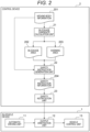
FIG. 2 is a diagram illustrating an outline of a functional block configuration and an overall operation flow of thecontrol system 0 according to the first embodiment. - The in-
vehicle device 1 includes anautomatic driving unit 11, anoutput arbitration unit 12, and avehicle control unit 13. - The
control device 2 includes a blockagecandidate calculation unit 21, a safetyinstruction generation unit 22, and asafety notification unit 23. - The
automatic driving unit 11 calculates a control command value of a vehicle on the basis of a sensor mounted on the vehicle, and controls the vehicle. - The
output arbitration unit 12 arbitrates the control command value on the basis of the output of theautomatic driving unit 11 and the output of thesafety notification unit 23, and inputs the control command value to thevehicle control unit 13. - The
vehicle control unit 13 controls the vehicle on the basis of the arbitrated control command value. - The blockage
candidate calculation unit 21 calculates theblockage area 202 and thewarning area 203 on the basis of the movingbody information 201 such as the position, speed, and travel plan received from the in-vehicle device 1 or the movingbody 3. - The safety
instruction generation unit 22 performs the blockage control on the basis of theblockage area 202, thewarning area 203, and themoving body information 201, and generatessafety instruction information 204. - The
safety notification unit 23 notifies (theoutput arbitration unit 12 of) the in-vehicle device 1 of thesafety instruction information 204. -
FIG. 3 is a diagram illustrating an example of themoving body information 201 in the present embodiment. - The
moving body information 201 manages a position, a speed, a type, and a path (travel plan) of each moving body (in-vehicle device 1 and moving body 3) existing in the assumed environment of the present embodiment by assigning an ID. This information may be notified to thecontrol device 2 by each moving body (in-vehicle device 1 and moving body 3), or may be detected by using an infrastructure sensor or the like. In the present embodiment, the type of each moving body is classified into at least a moving body capable of controlling an action (for example, an unmanned vehicle) and a moving body incapable of controlling an action (for example, a manned vehicle or a person). In other words, in the present embodiment, the type of each moving body is classified into an automatic driving vehicle (for example, an unmanned vehicle), a non-automatic driving vehicle (for example, a manned vehicle), and a person (pedestrian) . In addition, for example, since a manned vehicle is driven by a person, it is conceivable that the manned vehicle has current speed information but does not include information on a path in which the manned vehicle travels. On the other hand, even in a manned vehicle, for example, there may be a destination, and a path to the destination may be determined. The same applies to the pedestrian, but it is conceivable that the pedestrian does not have speed information because the traveling direction and the speed of the pedestrian are easily changed. -
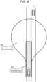
FIGS. 4 and5 are diagrams illustrating examples of theblockage area 202 and thewarning area 203 in the present embodiment. - The
blockage area 202 is an area indicated by hatching inFIGS. 4 and5 . Thewarning area 203 is an area existing outside theblockage area 202. - The
blockage area 202 is an area where a specific moving body (in-vehicle device 1) travels until the specific moving body stops by applying braking. - The
warning area 203 is an area necessary for preventing collision even when the movingbody 3 moves. - As illustrated in
FIG. 4 , it is conceivable that the vehicle is traveling (straight) on a straight road, and as illustrated inFIG. 5 , it is also conceivable that the vehicle is traveling on a curve. Although not illustrated, the area is determined according to various traveling patterns such as right/left turning. -
FIG. 6 is a diagram illustrating an example of thesafety instruction information 204 in the present embodiment. - As illustrated in
FIG. 6 , a safety instruction such as deceleration is issued to a target vehicle. -
FIG. 7 is a diagram illustrating a processing flow of the blockagecandidate calculation unit 21 in the present embodiment. - As shown in step S211, the premise is as follows.
- Coordinate system: Vehicle coordinate system (Vehicle coordinate system and world coordinate system can be transformed.)
- Current position: (0, 0)
- Trajectory of host vehicle: y = f(x)
- Current speed (m/s): V0
- Deceleration (m/s^2): -A
- In step S212, the braking time T_stop is calculated. The braking time is determined by T_stop = V0/A.
- In step S213, the braking distance D_stop is calculated. The braking distance is obtained by D_stop = V0*T_stop + (-A*T_stop^2)/2.
- In step S214, the stop position of the host vehicle is set to (X_stop, Y_stop), and stop position X_stop satisfies the following (Math. 1).

- In step S215, the
blockage area 202 is calculated. - In step S216, the
warning area 203 is calculated. -
FIG. 8 is a diagram illustrating a specific example for calculation of theblockage area 202. - The
blockage area 202 is obtained from a vehicle width, a vehicle length, a trajectory (travel plan), a position, a speed, and an acceleration (deceleration). An example will be described below. - When the
blockage area 202 is calculated, the trajectory on the left side of the vehicle is represented by y = g(x), and the area on the right side of the vehicle is represented by y = h(x). - Consider an arbitrary point (a, f(a)) on the trajectory.
- Since the inclination of the tangent at any point is f' (a), it can be seen that the inclination of the normal is -1/f' (a) . (When the inclination of the tangent and the inclination of the normal are multiplied, -1 is obtained. That is, it can be seen that they are orthogonal to each other.)
- Since the normal passes through an arbitrary point (a, f(a)), the normal can be expressed by y = -1/f' (a) *x + a/f' (a) + f(a).
- Next, functions on the left and right sides of the vehicle will be considered. An intersection point with the normal is defined as (c, d).
- Since (c, d) passes through the normal, d = (a-c)/f'(a) + f(a).
- Since the vehicle size is constant, the distance D_vehicle width margin between an arbitrary point and an intersection (c, d) is always constant. That is, (a-c)^2 + (f(a)-d)^2 = D_vehicle
width margin^ 2. - From these, by substituting d, (Math. 2) of the following equation is obtained.

- Since the range of a is 0 ≤ a ≤ X_stop, the left side is -D_vehicle width margin ≤ x ≤ X_stop-f' (X_stop) *D_vehicle width margin, and the right side is D_vehicle width margin ≤ x ≤ X_stop + f' (X_stop) *D_vehicle width margin.
- By the obtained c, since the left side is in the negative direction of x and the right side is in the positive direction of x, (Math. 3) of the following equation is obtained.

- As illustrated in
FIG. 8 , theblockage area 202 is an area obtained by extending g(x) and h(x) by the vehicle length margin. - In addition, in a case where there is a section in which the trajectory cannot be expressed by y = f(x), x = (arbitrary constant), so that the
blockage area 202 can be determined as the following (Math. 4).-D_vehicle width margin ≤ x ≤ D_vehicle width margin, -D_vehicle length margin ≤ y ≤ D_stop + vehicle length margin -
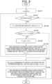
FIG. 9 is a diagram illustrating another example of the processing flow of calculation of theblockage area 202.FIG. 10 is a diagram illustrating a specific example when theblockage area 202 is calculated by the processing flow illustrated inFIG. 9 . - In step S2151, i and D_sum are initialized to 0.
- In step S2152, it is determined whether or not a waypoint (WP) exists, and in a case where the waypoint exists, the process proceeds to step S2153, and in a case where the waypoint does not exist, the process ends.
- In step S2153, the distance between the waypoints to be processed is calculated.
- In step S2154, it is determined whether the sum of the distances (D_sum) so far and the sum of the distances (D_i) between the waypoints to be processed exceed the braking distance (D_stop). If the sum exceeds the braking distance, the process proceeds to step S2157, and otherwise, the process proceeds to step S2155.
- In step S2155, the distance between the waypoints to be processed is added to the sum of the distances so far.
- In step S2156, the blockage area is calculated in consideration of the vehicle length and the vehicle width for the line segment of the waypoint to be processed. The processing proceeds to the next waypoint.
- The areas are as shown in WP_1 and WP_2 in
FIG. 10 . - In step S2157, a stop position is calculated such that the distance between WP_i and the stop position (WP_stop) becomes a difference between the braking distance (D_stop) and the sum (D_sum) of the distances until now.
- In step S2158, the blockage area is calculated in consideration of the vehicle length and the vehicle width with respect to the line segment between WP_i and the stop position (WP_stop). Areas such as WP_3 and a stop position (X_stop, Y_stop) in
FIG. 10 are obtained. For example, in the case ofFIG. 10 , (distance between WP_1 and WP_2) + (distance between WP_2 and WP_3) + (distance between WP_3 and stop position) = D_stop is obtained. - The blockage area is calculated by such a procedure.
- That is, in the present embodiment, the blockage
candidate calculation unit 21 calculates the blockage area on the basis of the position, the travel plan, and the speed of the in-vehicle device 1, which is a specific moving body, in the in-vehicle device 1. Specifically, in the in-vehicle device 1 that is a specific moving body, the blockagecandidate calculation unit 21 calculates the braking distance and the braking time on the basis of the position, the travel plan, and the speed of the in-vehicle device 1, and calculates an area based on the travel plan and the braking distance as the blockage area. - The
warning area 203 is an area where the movingbody 3 can move until a specific moving body (in-vehicle device 1) brakes and stops, and is obtained from the braking time and trajectory of the specific moving body (in-vehicle device 1) and the speed (current speed or assumed maximum speed) of the movingbody 3. An example is shown below. - It is assumed that the trajectory of the host vehicle can be expressed as x = f_x(t) and y = f_y(t) using a parameter t (t represents time, and 0 ≤ t ≤ T_stop).
- The
warning area 203 can be calculated as in the following (Math. 5).(x - f_x(t))^2 + (y - f_y(t))^2 ≤ (V_other * t)^2, 0 ≤ t ≤ T_stop - V_other is the speed of the moving
body 3, and the current speed may be referred to from the movingbody information 201, or the assumed maximum speed of the movingbody 3 may be referred to. - That is, in the present embodiment, in the in-
vehicle device 1 that is a specific moving body, the blockagecandidate calculation unit 21 calculates the warning area outside the blockage area on the basis of the blockage area, the braking time of the in-vehicle device 1, and the peripheral information (speed of the moving body 3 (current speed or assumed maximum speed), and the like). Specifically, the blockagecandidate calculation unit 21 calculates, as the warning area, an area where the movingbody 3 can move outside the blockage area during the braking time on the basis of the blockage area and the braking time of the in-vehicle device 1 and the speed of the movingbody 3 or the assumed maximum speed of the movingbody 3. In other words, the blockagecandidate calculation unit 21 calculates, as the warning area, an area where the movingbody 3 travels outside the blockage area during the braking time on the basis of the position and the travel plan of the movingbody 3, and the speed of the movingbody 3 or the assumed maximum speed of the movingbody 3. -
FIG. 11 is a diagram illustrating a processing flow of the safetyinstruction generation unit 22. - In step S221, it is determined whether or not the moving body 3 (another moving body) exists in the
blockage area 202, in a case where the moving body 3 (another moving body) exists, the process proceeds to step S226, and in a case where the movingbody 3 does not exist, the process proceeds to step S222. - In step S222, it is determined whether or not the moving
body 3 exists in thewarning area 203, and in a case where the movingbody 3 exists, the process proceeds to step S223, and in a case where the movingbody 3 does not exist, the process ends. - In step S223, it is determined whether or not the moving
body 3 is an unmanned vehicle, and in a case where the movingbody 3 is an unmanned vehicle, the process proceeds to step S224, and in a case where the movingbody 3 is not an unmanned vehicle, the process proceeds to step S226. - In step S224, it is determined whether or not the travel plan is a plan not to intrude into the
blockage area 202, and in a case where the travel plan is a plan not to intrude into theblockage area 202, the process is terminated, and in a case where the travel plan is a plan to intrude into theblockage area 202, the process proceeds to step S225. - In step S225, it is determined whether or not the host vehicle is prioritized, and in a case where the host vehicle is prioritized, the process is terminated, and in a case where the host vehicle is not prioritized, the process proceeds to step S226.
- In step S226, the safety instruction information 204 (
FIG. 6 ) is generated. - In such a procedure, the safety
instruction generation unit 22 determines contents to be instructed to the vehicle. - That is, the safety
instruction generation unit 22 generates the safety action instruction (safety instruction information 204) on the basis of the type (blockage area, warning area) of the area calculated by the blockagecandidate calculation unit 21 and the type (unmanned vehicle, manned vehicle, etc.) of the moving body 3 (another moving body) intruding into the area. - The
safety notification unit 23 notifies (theoutput arbitration unit 12 of) the in-vehicle device 1 of the safety action instruction (safety instruction information 204) generated by the safetyinstruction generation unit 22. - According to the
control system 0, the in-vehicle device 1, and thecontrol device 2 in the first embodiment, theblockage area 202 and thewarning area 203 are calculated, and braking is performed in a case of intrusion into theblockage area 202 or thewarning area 203, so that it is possible to prevent collision with the movingbody 3. In addition, by permitting intrusion depending on the type of the movingbody 3, traveling efficiency can be improved. - A
control system 0 according to a second embodiment of the present invention will be described. - The difference from the first embodiment is that, by permitting the intrusion of the moving
body 3 into thewarning area 203 by adding therule information 205, it is possible to improve the traveling efficiency while ensuring the safety when the rule is observed. - Note that the same components as those of the first embodiment are denoted by the same reference numerals, and the description thereof will be omitted.
-
FIG. 12 is a diagram illustrating a processing flow of the safetyinstruction generation unit 22 in the second embodiment. - In step S227, rule information is acquired.
- In step S221, it is determined whether or not the moving body 3 (another moving body) exists in the
blockage area 202, in a case where the moving body 3 (another moving body) exists, the process proceeds to step S226, and in a case where the movingbody 3 does not exist, the process proceeds to step S222. - In step S222, it is determined whether or not the moving
body 3 exists in thewarning area 203, in a case where the movingbody 3 exists, the process proceeds to step S228, and in a case where the movingbody 3 does not exist, the process ends. - In step S228, with reference to the
rule information 205, it is determined whether to permit the intrusion of the movingbody 3 existing in thewarning area 203, in a case where the intrusion is permitted, the process is terminated, and in a case where the intrusion is not permitted, the process proceeds to step S226. - In step S226, the safety instruction information 204 (
FIG. 6 ) is generated. - In such a procedure, the safety
instruction generation unit 22 determines contents to be instructed to the vehicle. - That is, the safety
instruction generation unit 22 generates the safety action instruction (safety instruction information 204) on the basis of the rule in addition to the type (blockage area, warning area) of the area calculated by the blockagecandidate calculation unit 21 and the type (unmanned vehicle, manned vehicle, etc.) of the moving body 3 (another moving body) intruding into the area. -
FIG. 13 is a diagram illustrating an example ofrule information 205 in the second embodiment. - For example, when the moving
body 3 that has intruded into thewarning area 203 is an unmanned vehicle (controllable), control (traveling/deceleration as it is) is performed according to the priority. - When a manned vehicle (uncontrollable) or a pedestrian (worker/external worker) is present in the
warning area 203, the processing is determined on the basis of rules. - In the case of a pedestrian (worker) on the sidewalk, since rule compliance is thorough, it can be determined that the pedestrian does not jump out to the roadway, and it is possible to permit the pedestrian to intrude into the sidewalk area in the
warning area 203. On the other hand, in the case of a pedestrian (external worker), it is difficult to comply with the rules thoroughly, and therefore intrusion into the sidewalk area is not permitted. - In a case where there is a separation zone on the roadway, it can be determined that there is no possibility that the oncoming vehicle intrudes into the traveling lane, so that the intrusion of the moving
body 3 into the roadway area can be permitted. - In the case of a crosswalk, since there is a possibility that a pedestrian will cross, intrusion into the crosswalk area is not permitted.
- In a case where there are a plurality of lanes, there is a possibility of collision when the manned vehicle makes a sudden lane change, and thus intrusion into the lane area is not permitted. On the other hand, in the case of the lane change prohibited section, since the lane cannot be changed, intrusion into the lane area is permitted.
- For example, in a case where an article such as a container is placed on a road or in a case where the article can be moved by a device such as a crane, it is determined that there is a possibility of collision in the movable range, and intrusion into the work area is not permitted. In other words, when the vehicle interferes with the area, the vehicle on which the in-
vehicle device 1 is mounted decelerates/stops. - As described above, the safety
instruction generation unit 22 generates the safety action instruction (safety instruction information 204) on the basis of a rule including road information such as a sidewalk, a separation zone, a crosswalk, a plurality of lanes, and a work area. - According to the
control system 0, the in-vehicle device 1, and thecontrol device 2 in the second embodiment, therule information 205 is added to permit the intrusion of the movingbody 3 into thewarning area 203, so that it is possible to improve the traveling efficiency while ensuring the safety in the case of observing the rule. - A
control system 0 according to a third embodiment of the present invention will be described. - The difference from the first and second embodiments is that by defining a safety instruction to an intruding moving body in the
rule information 205, a warning is issued to theintruding moving body 3, so that safety can be improved. - The same components as those in the first and second embodiments are denoted by the same reference numerals, and the description thereof will be omitted.
-
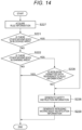
FIG. 14 is a diagram illustrating a processing flow of the safetyinstruction generation unit 22 in the third embodiment. - In step S227,
rule information 205 is acquired. - In step S221, it is determined whether or not the moving body 3 (another moving body) exists in the
blockage area 202, in a case where the moving body 3 (another moving body) exists, the process proceeds to step S226, and in a case where the movingbody 3 does not exist, the process proceeds to step S222. - In step S222, it is determined whether or not the moving
body 3 exists in thewarning area 203, in a case where the movingbody 3 exists, the process proceeds to step S228, and in a case where the movingbody 3 does not exist, the process ends. - In step S228, with reference to the
rule information 205, it is determined whether to permit the intrusion of the movingbody 3 existing in thewarning area 203, in a case where the intrusion is permitted, the process is terminated, and in a case where the intrusion is not permitted, the process proceeds to step S226. - In step S226, the safety instruction information 204 (
FIG. 6 ) is generated. - In step S229, the intruding moving body notification information is generated. It is assumed that the moving body (manned vehicle, pedestrian) has a device having a function of notifying the intruding moving body notification information notified from the
control device 2 by at least one of sound, light, vibration, and video. The moving body (manned vehicle, pedestrian) to which this information is notified is warned by at least one of sound, light, vibration, and video by a device possessed by the moving body. - In such a procedure, the safety
instruction generation unit 22 determines contents to be instructed to the vehicle. -
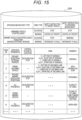
FIG. 15 is a diagram illustrating an example ofrule information 205 in the third embodiment. - As illustrated in
FIG. 15 , when the manned vehicle/pedestrian intrudes into theblockage area 202, thecontrol device 2 transmits the intruding moving body notification information, and a warning is issued through a device possessed by the manned vehicle/pedestrian. - In addition, when the manned vehicle/pedestrian intrudes into the
warning area 203, in a case where the intrusion is not permitted, thecontrol device 2 transmits the intruding moving body notification information, and a warning is issued through a device possessed by the manned vehicle/pedestrian. - According to the
control system 0, the in-vehicle device 1, and thecontrol device 2 in the third embodiment, by defining a safety instruction to an intruding moving body in therule information 205, it is possible to improve safety by issuing a warning to theintruding moving body 3. - A
control system 0 according to a fourth embodiment of the present invention will be described. - The difference from the first, second, and third embodiments is that when interference is expected, the number of times of acceleration/deceleration can be reduced and stable traveling can be realized by adjusting the speed of a specific moving body (in-vehicle device 1).
- Note that the same reference numerals are given to the same configurations as those of the first, second, and third embodiments, and the description thereof will be omitted.
-
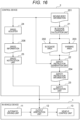
FIG. 16 is a diagram illustrating an outline of a functional block configuration and an overall operation flow of thecontrol system 0 in the fourth embodiment. - In addition to the configuration of the first embodiment, the
control device 2 includes aspeed adjuster 24 that calculatesspeed information 206 on the basis of the movingbody information 201 and aspeed notification unit 25 that transmits (notifies) thespeed information 206 to (theoutput arbitration unit 12 of) the in-vehicle device 1. -
FIG. 17 is a diagram illustrating a processing flow of thespeed adjuster 24 in the present embodiment. - In step S241, an intersection between the trajectory and the crosswalk is calculated. Since the crosswalk can be expressed by a function, an intersection (X_crosswalk, Y_crosswalk) with the trajectory can be calculated.
- In step S242, the distance between the moving
body 3 and the crosswalk is calculated. A pedestrian (X3, Y3) inFIG. 3 will be described as an example. Distance D_crosswalk can be calculated by √((X3-X_crosswalk)^2 + (Y3-Y_crosswalk)^2). - In step S243, an adjustment speed is calculated. Adjustment speed V_adjustment can be calculated by V_adjustment = (A/V_other)*(D_crosswalk-D_pedestrian margin).
- In step S244, it is determined whether or not (X_crosswalk-X_stop)^2 + (Y_crosswalk-Y_stop)^2 is smaller than (V_other*T_stop)^2, and if not, the process proceeds to step S245, otherwise the process ends.
- In step S245, it is determined whether or not V0 is larger than V_adjustment. If V0 is larger than V_adjustment, the process proceeds to step S246. If not, the process ends.
- In step S246, the V_adjustment is output to (the
output arbitration unit 12 of) the in-vehicle device 1 as the speed information 206 (the speed notification unit 25). - In such a procedure, the
speed adjuster 24 calculates a speed (V_adjustment) for preventing interference, and notifies (theoutput arbitration unit 12 of) the in-vehicle device 1 of V_adjustment when the current speed is larger than V_adjustment. - That is, in the present embodiment, the
speed adjuster 24 of thecontrol device 2 outputs the speed instruction (speed information 206) (for speed adjustment) to the in-vehicle device 1 when the position of the movingbody 3 after an arbitrary time is positioned in the blockage area or the warning area of the in-vehicle device 1 on the path where a specific moving body (in-vehicle device 1) moves. -
FIG. 18 is a diagram illustrating a blockage area and a warning area when the vehicle travels at the current speed.FIG. 19 is a diagram showing the blockage area and the warning area when the speed is adjusted. A specific example will be described with reference toFIGS. 18 and19 . - As illustrated in
FIG. 18 , in the case of traveling at the current speed, for example, it is conceivable that a pedestrian (moving body 3) intrudes into thewarning area 203. In the case ofFIG. 18 , since it is near the crosswalk, intrusion into thewarning area 203 is not permitted, and thus the deceleration instruction is notified to the in-vehicle device 1. However, since thewarning area 203 is reduced by deceleration, the intrusion state is eliminated and the vehicle is accelerated to the target speed again. - Therefore, as illustrated in
FIG. 19 , by determining the speed on the basis of a margin and setting the warning area 203 (small), it is possible to prevent frequent acceleration/deceleration and realize stable traveling while ensuring safety. - According to the
control system 0, the in-vehicle device 1, and thecontrol device 2 in the fourth embodiment, when interference is expected, the number of times of acceleration/deceleration can be reduced by adjusting the speed of a specific moving body (in-vehicle device 1), and stable traveling can be realized. - A
control system 0 according to a fifth embodiment of the present invention will be described. - The difference from the first, second, third, and fourth embodiments is that by transmitting the moving
body information 201, the information on theblockage area 202, and thewarning area 203 to the in-vehicle device 1, a trajectory for avoiding the area is calculated in theautomatic driving unit 11, and traveling can be performed without generating interference. - Note that the same reference numerals are given to the same configurations as those of the first, second, third, and fourth embodiments, and the description thereof will be omitted.
-
FIG. 20 is a diagram illustrating an outline of a functional block configuration and an overall operation flow of thecontrol system 0 in the fifth embodiment. - In addition to the configuration of the first embodiment, the
control device 2 includes ablockage instruction unit 26 that transmits (notifies) the movingbody information 201, theblockage area 202, and thewarning area 203 to (theautomatic driving unit 11 of) the in-vehicle device 1. - In addition, the
automatic driving unit 11 can calculate a trajectory for avoiding theblockage area 202 and thewarning area 203 by a known path planning method. - That is, the in-
vehicle device 1 includes the blockage control cooperativeautomatic driving unit 11 that does not travel outside theblockage area 202 notified from thecontrol device 2. Furthermore, in the present embodiment, (theautomatic driving unit 11 of) the in-vehicle device 1 can calculate an avoidance trajectory for avoiding theblockage area 202 and thewarning area 203 on the basis of the moving body information, the blockage area information, and the warning area information. - According to the
control system 0, the in-vehicle device 1, and thecontrol device 2 in the fifth embodiment, by transmitting the information of theblockage area 202 and thewarning area 203 to the in-vehicle device 1, it is possible to calculate a trajectory for avoiding the area in theautomatic driving unit 11 and travel without generating interference. - As described above, the control system 0 of the present embodiment is a control system 0 including a moving body (in-vehicle device 1 and moving body 3) and a control device 2, in which the control device 2 includes: a blockage candidate calculation unit 21 that calculates, in a specific moving body (in-vehicle device 1), a blockage area 202 on the basis of a position, a travel plan, and a speed of the specific moving body, and calculates a warning area 203 (outside the blockage area 202) on the basis of the blockage area 202, a braking time of the specific moving body, and peripheral information (such as a speed of the moving body 3 (current speed or assumed maximum speed)), a safety instruction generation unit 22 that generates a safety action instruction on the basis of a type of the area (blockage area 202, warning area 203) calculated by the blockage candidate calculation unit 21 and a type (unmanned vehicle, manned vehicle) of an intruding moving body (moving body 3) (around the specific moving body) that intrudes into the area, and a safety notification unit 23 that notifies the specific moving body of the safety action instruction, and the specific moving body performs an action on the basis of the safety action instruction notified from the safety notification unit 23.
- The intruding moving body (moving body 3) in the safety
instruction generation unit 22 means a moving body that has intruded into theblockage area 202 or thewarning area 203 of the specific moving body, and the specific moving body (in-vehicle device 1) in the safetyinstruction generation unit 22 means a moving body that has been intruded into theblockage area 202 or thewarning area 203 by the intruding moving body. - According to the present embodiment, the
blockage area 202 and thewarning area 203 are calculated, the intrusion of the moving body is not permitted in theblockage area 202, and the intrusion is permitted in thewarning area 203 according to the type of the moving body, so that it is possible to ensure safety even in a human-mixed environment and to perform efficient travel arbitration. - Note that the present invention is not limited to the above-described embodiments, and includes various modifications. For example, the above-described embodiments have been described in detail in order to explain the present invention in an easy-to-understand manner, and are not necessarily limited to those having all the described configurations. In addition, a part of the configuration of a certain embodiment can be replaced with the configuration of another embodiment, and the configuration of another embodiment can be added to the configuration of a certain embodiment. In addition, it is possible to add, delete, and replace other configurations for a part of the configuration of each embodiment.
- Further, each of the configurations, functions, processing units, processing means, etc. described above may be implemented by hardware, for example, by designing part or all of them with an integrated circuit. Further, each configuration, function, etc. described above may be implemented by software by the processor interpreting and executing a program that implements each function. Information such as a program, a table, and a file for implementing each function can be placed in a memory, a hard disk, a storage device such as a solid state drive (SSD), or a recording medium such as an IC card, an SD card, or a DVD.
- Further, control lines and information lines indicate what is considered to be necessary for the description, and not all control lines and information lines in the product are necessarily shown. In practice, almost all configurations may be considered to be mutually connected.
-
- 0
- control system
- 1
- in-vehicle device (specific moving body)
- 11
- automatic driving unit
- 12
- output arbitration unit
- 13
- vehicle control unit
- 2
- control device
- 21
- blockage candidate calculation unit
- 22
- safety instruction generation unit
- 23
- safety notification unit
- 24
- speed adjuster
- 25
- speed notification unit
- 26
- blockage instruction unit
- 201
- moving body information
- 202
- blockage area
- 203
- warning area
- 204
- safety instruction information
- 205
- rule information
- 206
- speed information
- 3
- moving body (intruding moving body)
Claims (15)
- A control system including a moving body and a control device, the control device including:a blockage candidate calculation unit that calculates, in a specific moving body, a blockage area on a basis of a position, a travel plan, and a speed of the specific moving body, and calculates a warning area on a basis of the blockage area, a braking time of the specific moving body, and peripheral information;a safety instruction generation unit that generates a safety action instruction on a basis of a type of an area calculated by the blockage candidate calculation unit and a type of an intruding moving body intruding into the area; anda safety notification unit that notifies the specific moving body of the safety action instruction,wherein the specific moving body performs an action on a basis of the safety action instruction notified from the safety notification unit.
- The control system according to claim 1, wherein the control device includes a blockage instruction unit that notifies the specific moving body of the blockage area information, the warning area information, and the moving body information.
- The control system according to claim 1, wherein the control device includes a speed adjuster that outputs a speed instruction to the specific moving body when a position of the intruding moving body after an arbitrary time is positioned in the blockage area or the warning area of the specific moving body in a path on which the specific moving body moves.
- The control system according to claim 1, whereinthe blockage candidate calculation unitcalculates a braking distance and a braking time on a basis of a position, a travel plan, and a speed of the specific moving body in the specific moving body, and calculates an area based on the travel plan and the braking distance as the blockage area, andcalculates, as the warning area, an area where the intruding moving body can move outside the blockage area during the braking time on a basis of the blockage area, the braking time, and a speed of the intruding moving body or an assumed maximum speed of the intruding moving body.
- The control system according to claim 1, whereinthe blockage candidate calculation unitcalculates a braking distance and a braking time on a basis of a position, a travel plan, and a speed of the specific moving body in the specific moving body, and calculates an area based on the travel plan and the braking distance as the blockage area, andcalculates, as the warning area, an area in which the intruding moving body travels outside the blockage area during the braking time on a basis of a position and a travel plan of the intruding moving body, and a speed of the intruding moving body or an assumed maximum speed of the intruding moving body.
- The control system according to claim 1, wherein the safety instruction generation unit generates a safety action instruction on a basis of a rule in addition to the type of the area calculated by the blockage candidate calculation unit and the type of the intruding moving body intruding into the area.
- The control system according to claim 1, wherein the type of the moving body is classified into at least a moving body capable of controlling an action and a moving body incapable of controlling an action.
- The control system according to claim 1, wherein the type of the moving body is classified into an automatic driving vehicle, a non-automatic driving vehicle, and a pedestrian.
- The control system according to claim 6, wherein the rule includes road information including at least one of a sidewalk, a separation zone, a crosswalk, a plurality of lanes, or a work area.
- The control system according to claim 1, wherein the intruding moving body in the safety instruction generation unit means a moving body that has intruded into the blockage area or the warning area of the specific moving body, and the specific moving body in the safety instruction generation unit means a moving body that has been intruded into the blockage area or the warning area by the intruding moving body.
- The control system according to claim 8, wherein the pedestrian or the manned vehicle has a device having a function of notifying intruding moving body notification information notified from the control device by at least one of sound, light, vibration, or video.
- The control system according to claim 1, wherein the specific moving body includes a blockage control cooperative automatic driving unit that does not travel outside the blockage area notified from the control device.
- The control system according to claim 1, wherein the specific moving body calculates an avoidance trajectory on a basis of the moving body information, the blockage area information, and the warning area information.
- A control method comprising:a blockage candidate calculation step of, in a specific moving body, calculating a blockage area on a basis of a position, a travel plan, and a speed of the specific moving body, and calculating a warning area outside the blockage area on a basis of the blockage area, a braking time of the specific moving body, and peripheral information;a safety instruction generation step of generating a safety action instruction on a basis of a type of an area calculated in the blockage candidate calculation step and a type of an intruding moving body intruding into the area; anda safety notification step of notifying the specific moving body of the safety action instruction.
- A control program for causing a computer to execute:a blockage candidate calculation procedure of, in a specific moving body, calculating a blockage area on a basis of a position, a travel plan, and a speed of the specific moving body, and calculating a warning area outside the blockage area on a basis of the blockage area, a braking time of the specific moving body, and peripheral information;a safety instruction generation procedure of generating a safety action instruction on a basis of a type of an area calculated in the blockage candidate calculation procedure and a type of an intruding moving body intruding into the area; anda safety notification procedure of notifying the specific moving body of the safety action instruction.
Applications Claiming Priority (2)
| Application Number | Priority Date | Filing Date | Title |
|---|---|---|---|
| JP2022137530A JP7794714B2 (en) | 2022-08-31 | 2022-08-31 | Control system, control method, and control program |
| PCT/JP2023/016705 WO2024047940A1 (en) | 2022-08-31 | 2023-04-27 | Control system, control method, and control program |
Publications (1)
| Publication Number | Publication Date |
|---|---|
| EP4583075A1 true EP4583075A1 (en) | 2025-07-09 |
Family
ID=90099211
Family Applications (1)
| Application Number | Title | Priority Date | Filing Date |
|---|---|---|---|
| EP23859711.6A Pending EP4583075A1 (en) | 2022-08-31 | 2023-04-27 | Control system, control method, and control program |
Country Status (4)
| Country | Link |
|---|---|
| US (1) | US20260051247A1 (en) |
| EP (1) | EP4583075A1 (en) |
| JP (1) | JP7794714B2 (en) |
| WO (1) | WO2024047940A1 (en) |
Family Cites Families (2)
| Publication number | Priority date | Publication date | Assignee | Title |
|---|---|---|---|---|
| JP6876178B1 (en) * | 2020-03-31 | 2021-05-26 | 日立建機株式会社 | Traffic control server, traffic control system, and display device capable of wireless communication with the traffic control server |
| JP7435787B2 (en) * | 2020-07-29 | 2024-02-21 | 株式会社Soken | Route confirmation device and route confirmation method |
-
2022
- 2022-08-31 JP JP2022137530A patent/JP7794714B2/en active Active
-
2023
- 2023-04-27 EP EP23859711.6A patent/EP4583075A1/en active Pending
- 2023-04-27 US US19/103,608 patent/US20260051247A1/en active Pending
- 2023-04-27 WO PCT/JP2023/016705 patent/WO2024047940A1/en not_active Ceased
Also Published As
| Publication number | Publication date |
|---|---|
| WO2024047940A1 (en) | 2024-03-07 |
| JP2024033743A (en) | 2024-03-13 |
| US20260051247A1 (en) | 2026-02-19 |
| JP7794714B2 (en) | 2026-01-06 |
Similar Documents
| Publication | Publication Date | Title |
|---|---|---|
| EP3867117B1 (en) | Responsive vehicle control | |
| US9308916B2 (en) | Driver-assistance system and method for operating the driver-assistance system | |
| CN114906164B (en) | Trajectory Validation for Autonomous Driving | |
| Schwarting et al. | Safe nonlinear trajectory generation for parallel autonomy with a dynamic vehicle model | |
| Wei et al. | A prediction-and cost function-based algorithm for robust autonomous freeway driving | |
| Hillenbrand et al. | A multilevel collision mitigation approach—Its situation assessment, decision making, and performance tradeoffs | |
| US8744648B2 (en) | Integrated framework for vehicle operator assistance based on a trajectory prediction and threat assessment | |
| US20180253103A1 (en) | Method and Device for Controlling a Trajectory Planning Process of an Ego-Vehicle | |
| Medina et al. | Automation of a T-intersection using virtual platoons of cooperative autonomous vehicles | |
| CN115884908B (en) | Route confirmation device and route confirmation method | |
| Eggert et al. | The foresighted driver model | |
| Rasekhipour et al. | Autonomous driving motion planning with obstacles prioritization using lexicographic optimization | |
| EP3925845B1 (en) | Other vehicle action prediction method and other vehicle action prediction device | |
| EP3527450B1 (en) | Vehicle control apparatus | |
| US11011059B2 (en) | Vehicle control device | |
| JP6315827B2 (en) | Driving assistance device | |
| CN115123262B (en) | Longitudinal acceleration control for autonomous driving | |
| Das et al. | Saint-acc: Safety-aware intelligent adaptive cruise control for autonomous vehicles using deep reinforcement learning | |
| EP3549837A1 (en) | Vehicle control apparatus | |
| CN116601064A (en) | Method for controlling vehicle when obstacles around the vehicle are detected; control device for vehicle having autonomous driving function module; computer readable medium and motor vehicle | |
| WO2022185870A1 (en) | Processing method, processing system, and processing program | |
| Maki et al. | Stochastic model predictive obstacle avoidance with velocity reduction in accordance with chance constraints in crowded environments | |
| JP2019119237A (en) | Vehicle controller | |
| US20260051247A1 (en) | Control System, Control Method, and Control Program | |
| Cao et al. | Automotive longitudinal speed pattern generation with acceleration constraints aiming at mild merging using model predictive control method |
Legal Events
| Date | Code | Title | Description |
|---|---|---|---|
| STAA | Information on the status of an ep patent application or granted ep patent |
Free format text: STATUS: THE INTERNATIONAL PUBLICATION HAS BEEN MADE |
|
| PUAI | Public reference made under article 153(3) epc to a published international application that has entered the european phase |
Free format text: ORIGINAL CODE: 0009012 |
|
| STAA | Information on the status of an ep patent application or granted ep patent |
Free format text: STATUS: REQUEST FOR EXAMINATION WAS MADE |
|
| 17P | Request for examination filed |
Effective date: 20250331 |
|
| AK | Designated contracting states |
Kind code of ref document: A1 Designated state(s): AL AT BE BG CH CY CZ DE DK EE ES FI FR GB GR HR HU IE IS IT LI LT LU LV MC ME MK MT NL NO PL PT RO RS SE SI SK SM TR |
|
| RAP3 | Party data changed (applicant data changed or rights of an application transferred) |
Owner name: ASTEMO, LTD. |
|
| DAV | Request for validation of the european patent (deleted) | ||
| DAX | Request for extension of the european patent (deleted) |